

Page 1

CMS55 ICT
USER MANUAL
Page 2

CONTENTS
1. Introduction
2. Unpacking
i. CMS55 ICT (Loudspeaker, Baffle & Transformer)
ii CMS 55 BC (Ceiling Can)
iii CMS 55 TB (Tile Bridge Assembly)
3. Assembly instructions
4. Voltage & Power Selection
5. Equalisation
6. Dimensions
7. Technical Specifications
8. Performance Data
9. Recommended Service Parts & Accessories
10. Warranty
11. Declaration of Conformity
HOLE CUT-OUT SIZE – 208mm
Page 3

1. Introduction
The Tannoy CMS55 ICT Ceiling Monitor System is suited for high level music
and speech reinforcement applications requiring exceptional sonic quality with
uncompromised reliability. Achieving fast, simple and cost effective installation in
new and existing buildings, this versatile design has addressed the two most
common failures of background music and sound reinforcement systems, which
are firstly the tweeter, and secondly the crossover. With the revolutionary design
of the ICT™ drive unit, neither of the above criteria applies, assuring you years
of trouble free use.
ICT™ or Inductive Coupling Technology utilises a wireless electromagnetic tweeter
that does not require a crossover and can not be burned out from heavy or abusive
use. The 1” aluminium high frequency dome has a deep drawn skirt which sits on the
inside of the low frequency voice coil in the same magnetic gap. The skirt is like a
single shorted turn, which is induced with high frequency information generated by the
low frequency voice coil, which is fed a full bandwidth signal. The ICT™ dome is at the
heart of our 5” ceiling transducer which utilises a moulded plastic cone and nitryl
rubber surround to further enhance it’s durability and long term reliability.
The ICT driver is housed in a rugged aluminium ceiling enclosure that has been
optimally tuned to achieve maximum bass response and tonal balance.
The CMS55 ICT is powered by Tannoy’s THP 30 multi-tap transformer that provides
high system sensitivity, a wide bandwidth and dynamic range, with very low insertion
loss. For critical applications provision has been made for the CMS55 ICT to accept
the THP 60, a 60W multi-tap transformer.
2. Unpacking
Every Tannoy CMS55 ICT and accessory is carefully inspected before packing. After
unpacking, please inspect for any exterior physical damage, and save the carton and
any relevant packaging materials in case the loudspeaker again requires packing and
shipping. In the event that damage has been sustained in transit notify your dealer
immediately.
The complete CMS55 ICT package consists of three major components all packaged
and supplied as individual items: -
i. CMS55 ICT (Loudspeaker, Baffle & Transformer, Part No. 8000 0748)
ii CMS 55 BC (Ceiling Can, Part No. 8000 0749)
iii CMS 55 TB (Tile Bridge Assembly, Part No. 8000 0750)
Please check the contents of each package before assembly.
Page 4
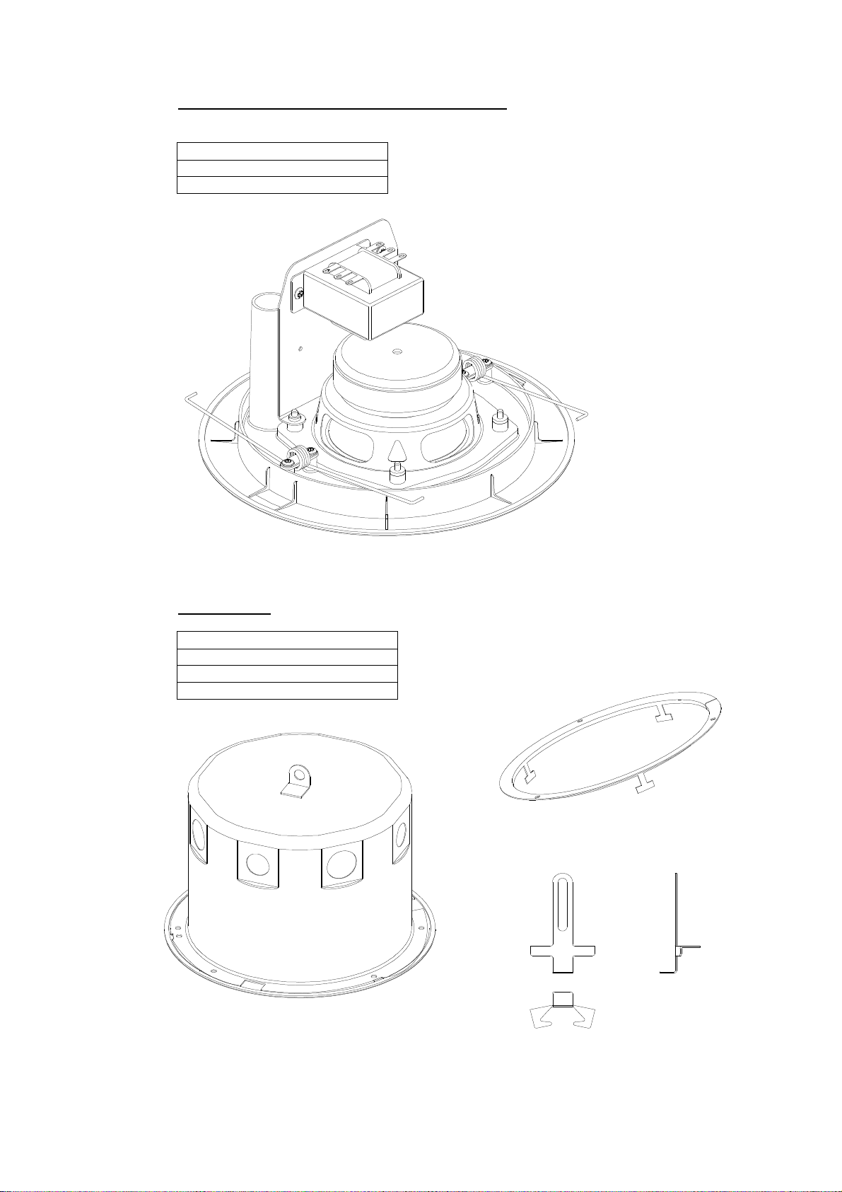
i. CMS55 ICT Loudspeaker, Baffle & Transformer
Contents:-
Baffle Assembly - Complete
Wadding Material
Baffle assembly
ii Ceiling Can
Contents:-
Back Can
C-Ring
2 x Sliding Clamp & Fixings
C-Ring
Back Can
Sliding Clamp
Page 5
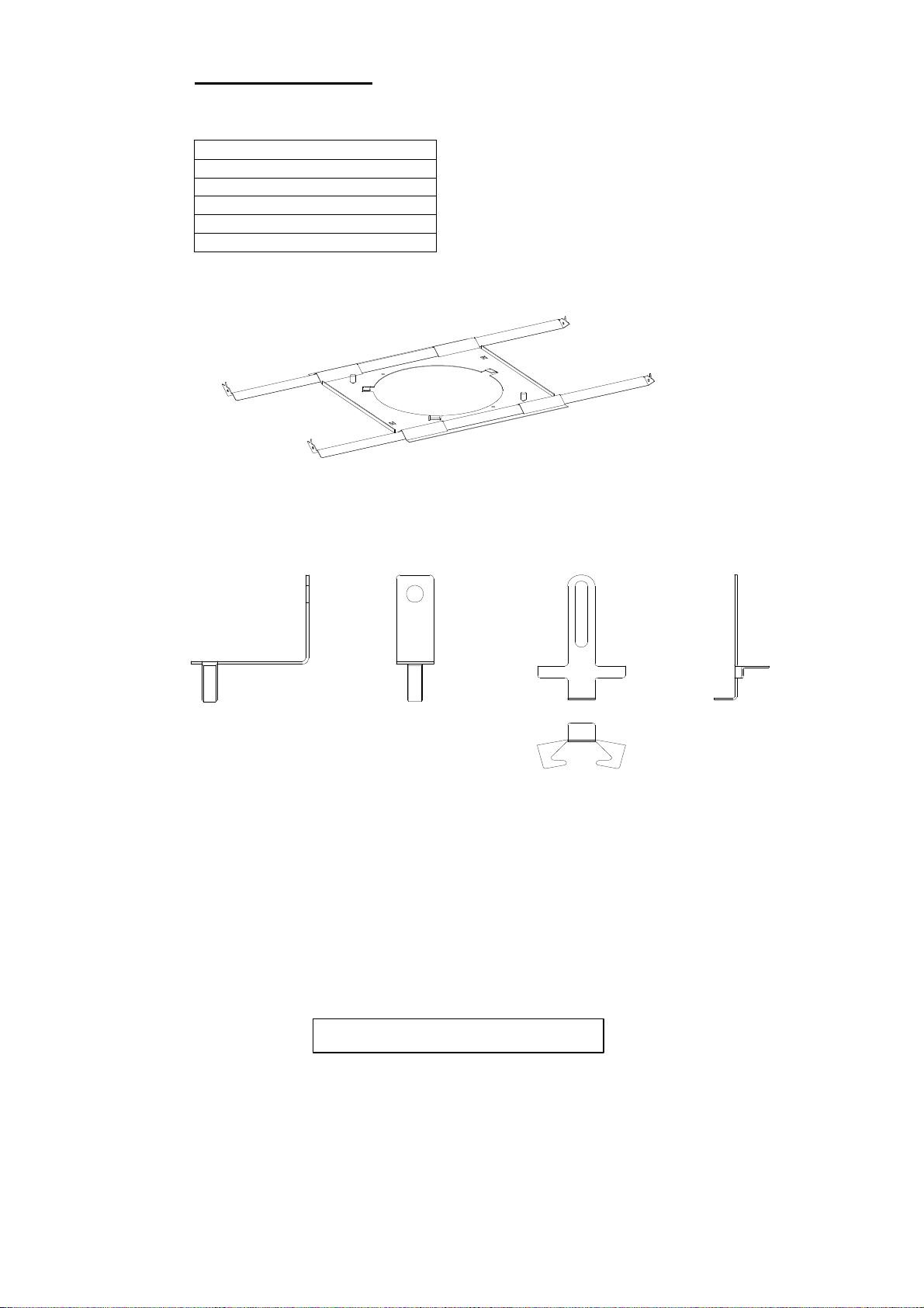
iii Tile Bridge Assembly
Contents:-
Tile Bridge
2 x Large Tile Support (angle)
2 x Small Tile Support (angle)
2 x Right Angle Bracket
2 x Sliding Clamp & Fixings
Tile Bridge (shown with tile supports assembled)
Right Angle Bracket
3. Assembly Instructions
There are 4 methods of assembly depending on application: i Baffle assembly and back can, back can fitted from above ceiling.
ii Baffle assembly and back can with c-ring. The use of the c-ring facilitates
installation from below the ceiling, where access is not possible from above.
iii Baffle assembly, back can and tile bridge.
iv Baffle assembly with tile bridge.
Sliding Clamp
Ceiling hole cut-out size – 208 mm
Page 6

i Baffle assembly and back can, back can fitted from above ceiling.
Fig a.
Fig b. Fig c.
Fit the sliding clamps to the M8 studs as shown in Fig b. do not tighten the wing nuts
at this stage. Place the back can over the hole and use the sliding clamp to sandwich
the roof material, tighten the wing nut to hold the back can firmly in position. Place the
wadding material that comes with the baffle assembly into the back can.
Important: Connect the safety cable to the rear of the transformer plate.
After connecting to the transformer (see section 4) squeeze the retaining springs
together as shown in fig c. Still holding the springs together place them into the sliding
clamp and gently push the baffle into position. There is an anchor point fitted to the
top of the back can (fig a.). For added safety this should be used.
The C-ring is not used for this method of installation and can be discarded.
There are 8 knock-out holes in the back-can (4 x 22mm & 4 x 28mm). When installing
conduit ensure the glands are airtight.
Page 7

ii Baffle assembly and back can with c-ring
Fig e.
Fit the sliding clamps to the M8 studs as shown in Fig b., push the sliding clamp until it
stops hard against the flange of the back can and fits into the indent, tighten the wing
nuts at this stage. Place the wadding material that comes with the baffle assembly into
the back can.
Important: Connect the safety cable to the rear of the transformer plate.
Place the three spring clips supplied over the screwholes on the c-ring (fig e.). The cring is split to facilitate positioning from below the ceiling if necessary. After positioning
the c-ring, bend the tabs back to secure the c-ring in place, push the back can through
the ceiling hole, ensure the tabs on the c-ring line up with the three indents on the
back can rim. Insert the three machined screws through the holes in the back can
flange and into the spring clips on the c-ring (fig e.). After connecting to the
transformer (see section 4) squeeze the retaining springs together as shown in fig c.,
still holding the springs together place them into the sliding clamp and gently push the
baffle into position. There is an anchor point fitted to the top of the back can (fig a.),
for added safety this should be used.
Page 8

iii Baffle assembly, back can and tile bridge.
Fig f.
Fit sliding clamps to the M8 studs in the back can as shown in Fig b. do not tighten the
wing nuts at this stage. Assemble the Tile Bridge as shown in Fig f. The spikes
highlighted in fig g. below can be bent at right angles to hold the assembly in position
before fixing the tile supports in position permanently. The back can is fixed into
position by rotating the can until the holes on the can flange line up with dimples on
the Tile Bridge (fig g.). Use the sliding clamp to sandwich the roof material, tighten the
wing nut to hold the back can and Tile Bridge firmly in position. Place the wadding
material that comes with the baffle assembly into the back can.
Important: Connect the safety cable to the rear of the transformer plate.
After connecting to the transformer (see section 4) squeeze the retaining springs
together as shown in fig c. Still holding the springs together place them into the sliding
clamp and gently push the baffle into position. There is an anchor point fitted to the
top of the back can (fig a.). For added safety this should be used.
The C-ring is not used for this method of installation and can be discarded.
Fig g.
Page 9

iv Baffle assembly with tile bridge
Fix the right angle brackets to the M8 studs on the tile bridge as shown in fig h.
Assemble the tile bridge and fit the sliding clamps to the right angle brackets as
shown in fig j. below. The spikes highlighted in fig g. can be bent at right angles to
hold the assembly in position before fixing the tile supports in position permanently.
Use the sliding clamp to sandwich the roof material, tighten the wing nut to hold the
tile bridge firmly in position. After connecting to the transformer (see section 4)
squeeze the retaining springs together as shown in fig c. Still holding the springs
together place them into the sliding clamp and gently push the baffle into position.
Fig h.
Fig j.
Page 10

4. Voltage & Power Selection
After deciding on a 70.7 or 100 volt system, determine the maximum power in watts
needed at each speaker location. The Tannoy THP30 transformer can be tapped at
30w, 15w, 7.5w, & 3.75 w. When the relevant tappings have been selected add the
individual wattages required at all speakers and select an amplifier with a rating equal
to or exceeding the total wattage required. All of the transformer primaries should be
connected in parallel to the output of this amplifier. If for example, you select the 7.5watt transformer tap, it means that at full rated amplifier output the speaker will
receive the full 7.5 watts. If the amplifier gain is reduced each speaker will receive a
proportional amount of power, maintaining the overall system balance.
When calculating amplifier wattage requirements for a system, it is recommended that
a generous wattage safety margin (3dB of headroom) be left so that the system does
not have to operate continuously at its full rated output.
Make sure the red cable (amplifier
end) is connected to the respective
voltage rating on the primary. The
black cable is connected to the
‘common’ on the transformer
primary.
When you have selected the desired
operating wattage, the brown wire
connected to the positive terminal of
the loudspeaker should be connected
to the relevant wattage tapping on
the transformer secondary. The blue
wire connected to the negative
terminal of the loudspeaker drive unit
is connected to the ‘common’ on the
transformer secondary.
Low impedance operation - If
required the CMS55 ICT can be used
as a conventional loudspeaker by
simply bypassing the THP30
transformer and connecting the
amplifier output to the loudspeaker
terminals.
THP30 transformer
In order to comply with relevant fire safety regulations (i.e. BS 5839:1998), it
is required that in the event of fire, that failure of the circuit to which the
loudspeaker is connected does not occur before evacuation of the building is
complete. Suitable measures include: -
a) use of terminal blocks (for connection to primary) with a melting point of
not less than 650°C, for example constructed from ceramic materials;
c) use of terminal blocks of a lower melting point but protected with thermal
insulation;
d) use of terminal blocks such that, on melting, an open-circuit or a short-
circuit does not occur.
Page 11

5. Equalisation
170.2
149.0
The CMS55 ICT is designed to need no equalisation or correction to overcome
system limitations. As a result, it will only need equalisation to compensate for difficult
acoustic environments.
Excess equalisation can reduce system headroom, and introduce phase distortion
resulting in greater problems than it cures. If equalisation is required then it should be
applied gently and smoothly. Violent equalisation will be detrimental to the overall
sound quality. If the loudspeakers were being used consistently at high levels it would
be beneficial to introduce a high-pass filter at 50Hz to protect the loudspeaker from
any unnecessary subsonic frequencies
6. Dimensions
245.0
202.4
Page 12

7. Technical Specifications
System Type Vented, full range ICT™ loudspeaker system
Frequency Response (1) +/- 3dB 80Hz - 20kHz
Power Handling(2) 60 watt
Sensitivity (1) 2.83 volt @ 1m 89 dB
Maximum SPL (3) @ 1m 103 dB (with THP 30 Transformer)
106 dB (@ 8Ω)
Impedance Nominal 8.0 ohm
Minimum 6.1 ohm
DI Averaged (PCQ) 7.8, 500 Hz – 16 kHz
@ 1kHz (ISO) 5.7
@ 2kHz (ISO) 6.8
@ 4kHz (ISO) 8.4
@ 8kHz (ISO) 9.5
@ 16kHz(ISO) 12.6
Q Averaged (PCQ) 7.5, 500 Hz - 16 kHz
@ 1kHz (ISO) 3.7
@ 2kHz (ISO) 4.8
@ 4kHz (ISO) 6.9
@ 8kHz (ISO) 8.9
@ 16kHz (ISO) 18.2
Driver Complement 1 x 5” (130mm) full range, ICT™ Point Source
Enclosure 4.3 litres, vented (in back can)
Finish White
System Weight (in back can) 1.75 kg
Dimensions Can height: 150mm
Baffle Diameter: 245mm
Hole cutout size: 208mm
Accessories Tile Bridge (optional)
NOTES: (1) Average over stated bandwidth. Measured at 1m on axis, in an anechoic chamber.
Tannoy operates a policy of continuous research and development. The introduction of new materials or manufacturing
methods will always equal or exceed the published specifications which Tannoy reserve the right to alter without prior notice.
Please verify the latest specifications when dealing with critical applications.
(2) Long term power handling capacity as defined in EIA standard RS - 426A.
(3) Unweighted pink noise input, measured at 1m.
Page 13

8. Performance Data
FREQUENCY RESPONSE IMPEDANCE
4 kHz
16 kHz
Page 14

9. CMS55 ICT Recommended Service Parts & Accessories
Part Number Description
7900 0538 Driver Kit – 1212 5”ICT
7600 0963 Transformer/Plate Assembly
8000 0748 CMS55 ICT (Loudspeaker, Baffle & Transformer)
8000 0749 CMS55 BC (Ceiling Can)
8000 0750 CMS55 TB (Tile Bridge Assembly)
10. Warranty
No maintenance of the CMS55 ICT loudspeaker is necessary.
All Tannoy professional loudspeaker products are covered by a 5 year warranty from
the date of manufacture subject to the absence of misuse, overload or accidental
damage. Claims will not be considered is the serial number has been altered or
removed. Work under warranty should only be carried out by a Tannoy Professional
dealer or service agent. This warranty in no way affects your statutory rights. For
further information please contact your dealer or distributor in your country. If you
cannot locate your distributor please contact Customer Services, Tannoy Ltd at the
address given below.
Customer Services
Tannoy Ltd.
Rosehall Industrial Estate
Coatbridge
Strathclyde
ML5 4TF
Scotland
Telephone: 01236 420199 (National)
+44 1236 420199 (International)
Fax: 01236 428230 (National)
+44 1236 428230 (International)
e-mail: prosales@tannoy.com
DO NOT SHIP ANY PRODUCT TO TANNOY WITHOUT PREVIOUS AUTHORISATION
Our policy commits us to incorporating improvements to our products through
continuous research and development. Please confirm current specifications for
critical applications with your supplier.
EASE Data for Tannoy Professional products available on request.
Page 15

Declaration of Conformity
The following apparatus is/are manufactured in the United Kingdom by Tannoy Ltd of
Rosehall Industrial estate, Coatbridge, Scotland, ML5 4TF and conform(s) to the
protection requirements of the European Electromagnetic Compatibility Standards
and Directives relevant to Domestic Electrical Equipment. The apparatus is designed
and constructed such that electromagnetic disturbances generated do not exceed
levels allowing radio and telecommunications equipment and other apparatus to
operate as intended, and, the apparatus has an adequate level of intrinsic immunity
to electromagnetic disturbance to enable operation as specified and intended.
Details of the Apparatus: Tannoy Monitor Loudspeaker
Model Number: CMS55 ICT
Associated Technical File: EMC CMS55 ICT
Applicable Standards: EN 50081-1 Emission
EN 50082-1 Immunity
Signed:
Position: Technical Manager
Tannoy Professional
Date: 22nd Feb 1999
For Tannoy Ltd
Page 16

Tannoy Loudspeakers are manufactured
in Great Britain by :
Tannoy Ltd, Rosehall Industrial Estate, Coatbridge,
Strathclyde, ML5 4TF, SCOTLAND
Telephone: +44 (0)1236 420199 Fax: +44 (0)1236 428230
Internet: http://www.tannoy.com
TGI/Tannoy, 300 Gage Avenue, Kitchener, Ontario, CANADA, N2M 2C8
Telephone: (519) 745 1158 Fax: (519) 745 2364
Tannoy Nederland BV, Anthonetta Kuijlstraat 19, 3066 GS, Rotterdam THE NETHERLANDS
Telephone: (010) 2860554 Fax: (010) 2860431
Tannoy is a member of the Group of Companies Issue 1 Part No. 6481 0314
GH 10 FEB 1999
 Loading...