


800 826 5537 03/24/2017
Model Number:_______________ Serial Number:________________
Information Manual…… Rev # 03.24.17
Installation and Troubleshooting Instructions for Electric Tankless Commercial Water Heaters
CE 12 KW, CE 15 KW, CE 18 KW CE 24 KW CE 27 KW CE 48 KW
CES 12 KW ,CES 15 KW, CES 18 KW CES 24 KW, CES 27 KW, CES 36 KW
CE 120 KW CE 144 KW or CE 108 KW CE 72 KW, CE 54 KW, or CE 48 KW
CES 120 KW CES 144 KW or CES 108 KW CES 72 KW, CES 54 KW, or CES 48 KW
FOR MORE DETAILED SCHEMATICS AND WIRING DIAGRAMS VISIT, HOTWATERHEATER.COM
2060 B Whitfield Park Avenue * Sarasota, FL 34243 * 800-826-5537 * tanklessinc@stiebel-eltron-usa.com
1

800 826 5537 03/24/2017
Table of Contents __________________________________
INFORMATION MANUAL for Commercial Heaters – Models
CE 12 KW CES 12 KW CE 15 KW CES 15 KW CE 18 KW CES 18 KW CE 24 KW CES 24 KW
CE 27 KW, CES 27 KW, CERO 27 KW, CE 36 KW CES 36 KW CERO 36 KW CE 48 KW
CES 48 KW CE 54 KW, CES 54 KW, CERO 54 KW, CERO 72 KW, CE 72 KW. CES 72 KW, CE 108 KW,
CES 108 KW, CE 120 KW, CES 120 KW, CE 144 KW, CES 144 KW
__________________________________
PAGE #
How a CE and CES Series Heaters Work 3
Controls Explanation 4
Engineering Information and Breaker Sizes 5
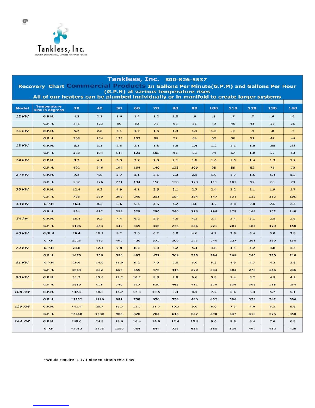
Recovery Capacities Chart 6
CE Series Installation 7
Assembly Drawing 12 KW 15 KW or 18 KW 8
Assembly Drawing 24 KW 27 KW 36 KW 9
Assembly Drawing 48 KW 54 KW 72 KW 10
Assembly Drawing 108 KW 120 KW 144 KW 11
Troubleshooting electronic three phase units 12-17
2

800 826 5537 03/24/2017
How an electronic Heater Works:
We have four lines of heaters; electromechanical (C series) and electronic (CE series), electronic (CES), and CERO series.
They all heat the fluid as it passes through but they are controlled in different manners depending on the customer’s
needs. This manual is specifically for the CE, CES, or CERO series units…..3 , 6 , 12 element or 24 element units for the CE and
CES series and 3,6,and 12 for the CERO units.
CE, CES, and CERO models: These models use a computer board to control the heating process. They need three pieces of
information to determine how much heat is necessary.
1. Water flow- This is determined by the flow meter and the information sent to the board. When the water tap opens,
the cold water entering the heater passes through the Flow Meter and the Flow Meter calculates how much water is
passing through the heater and it sends the signal to the Control Board once a second.
2. Inbound fluid temperature- A thermistor reads the inbound temperature of the water and sends a signal to the
Control Board.
3. Desired output temperature. The customer provides this information and can adjust the level using the rocker switch
at the left side of the unit for the 12 kw,15 kw, 18 kw, 36 kw, 48 kw, 54 kw, and 72 kw units and using either the
buttons on the board or the rocker switch on the right side for the 108 KW, 120 KW, or the 144 KW units.
4. On the CE and CERO series the acceptable temperature range the computer board will accept is 60-185 F and on the
CES series the output temperature is limited to 90 F.
5. The thermostats that shut down heating on the CE and CERO units are 200 F and on the CES series this mechanical
over temperature protection is at 90 F.
The Control Board takes the information given by the Flow Meter, the thermistor, and the customer and calculates every
second how many BTUs it needs to apply to the water to achieve the desired temperature and turns on the appropriate
number of elements.
Each time the unit turns on the series in which the elements turn on changes to balance out the element usage and to increase
the element life. This function is called dynamic load balancing.
The CERO units use special elements with titanium sheathing so be sure to order the correct part if you have a CERO model.
3

800 826 5537 03/24/2017
Controls Explanation CE , CES and CERO Series models
Options for factory software settings include the following items
Commercial water heaters Safety shower heaters
CE and CERO CES
Maximum temperature: 60 to 185 F 60 to 90 F
Initial output setting per customer request 85 F
Freeze protection at 40 degrees F Yes Yes
For use on a recirculation system Yes No
F or C F F
Flashing to show over capacity condition Yes Yes
Shows output temperature and
Requested output temperature intermittently
Each 60 seconds Yes Yes
RS 232 interface available Yes Yes
4

800 826 5537 03/24/2017
The following charts show the full load AMP draw, breakers required and physical size for each of our larger electronic units
(engineering chart) and the capabilities of each unit(recovery chart) in terms of temperature rise at a certain flow rate.
5
800 826 5537 03/24/2017
6
 Loading...