


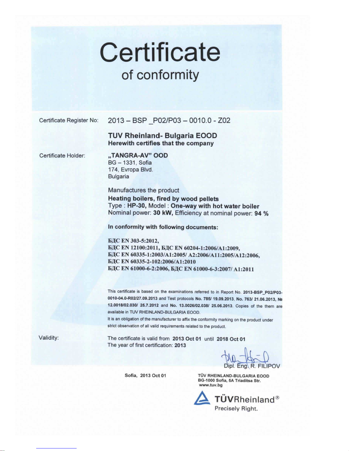
Manufactured in accordance with standard:
- EN 303-5
Rev. 04 - 2014-03-28
Installation and operation manual
for pellet boiler
T
ANGRA HP 30

User manual TANGRA HP30 - Rev. 04 - 2014-03-28 2

User manual TANGRA HP30 - Rev. 04 - 2014-03-28 3
Content
1. Introduction ........................................................................................................... 6
2. Safety ................................................................................................................... 7
3. GUARANGTEE CONDITIONS ............................................................................. 9
4. Description and construction ................................................................................ 9
4.1 Technical data .............................................................................................. 10
4.2 Main parts of the boiler „TANGRA HP 30” ................................................... 11
5. Transport and storage ........................................................................................ 12
5.1 Transport ...................................................................................................... 12
5.2 Transport to the technical room ................................................................... 12
5.3 Storage ........................................................................................................ 12
6. Installation .......................................................................................................... 13
6.1 Requirements for the technical room ........................................................... 13
6.2 Requirements for the chimney ..................................................................... 13
6.3 Requirements for the heating system ........................................................... 13
6.4 Boiler installation .......................................................................................... 14
6.4.1 Leveling of pellet boiler TANGRA CL35 ................................................ 15
6.5 Connection to the heating system ................................................................ 16
6.6 Electrical power supply ................................................................................ 17
7. Requirements to the pellets ................................................................................ 17
8. Commissioning ................................................................................................... 17
8.1 Filling the installation .................................................................................... 17
8.2 Initial filling of the auger ............................................................................... 17
8.3 Set the capacity of the boiler: ....................................................................... 18
8.4 Set the temperature in the boiler .................................................................. 19
8.5 Initial start up of the boiler ............................................................................ 19
8.6 Setting of the burning process ..................................................................... 19
8.7 Measure the draught in the chimney ............................................................ 19
9. Maintenance ....................................................................................................... 20
9.1 Cleaning of the combustion chamber ........................................................... 20
9.2 Annual maintenance .................................................................................... 20
10. Decommissioning ............................................................................................... 20
10.1 Dismantling and disposal ............................................................................. 20
11. Emergency activities ........................................................................................... 20
11.1 Overheating of the system ........................................................................... 21
11.2 Smell of flue gases ....................................................................................... 21
11.3 Fire ............................................................................................................... 21
12. Appendix ............................................................................................................. 22
12.1 Wiring diagram ............................................................................................. 22
13. User manual - controller ..................................................................................... 23
13.1 Turning on/off the boiler ............................................................................... 23
13.2 Schemes of the main menu ......................................................................... 25
13.3 Description of the functions .......................................................................... 26
13.4 Service menu of the boiler ........................................................................... 28
13.5 Parameters of the controller ......................................................................... 29

User manual TANGRA HP30 - Rev. 04 - 2014-03-28 4
User manual TANGRA HP30 - Rev. 04 - 2014-03-28 5

User manual TANGRA HP30 - Rev. 04 - 2014-03-28 6
Before start any installation, commissioning or service
works, please read very carefully this manual!
1. Introduction
The pellet boilers, manufactured by TANGRA, are produced in accordance with all applicable
Bulgarian and EU requirements.
Their installation and usage should be done according to the following instruction.
The manufacturer is not responsible for damages due to improper use.
This manual is an integral part of the unit. It should be kept in an easy accessible place for the
operating personnel. We recommend keeping it near the air handling unit.
By installation, dismantling, maintaining or cleaning the unit all safety rules should be strictly
observed. The use of personal protective equipment is required!
Changes in the construction of the unit and all its components without consulting the
manufacturer are unacceptable and could lead to improper work of the unit, damages or
incidents.
By decommissioning it is important to follow strictly the prescription for environmental protection,
as well as to dispose of the units in accordance with local regulation and practices for waste
management.
Safety symbols
The following symbols could be found on the products or in the current instruction:
DANGER
!
Warning! Electricity! Components under voltage!
Warning
!
General warning sign.
Attention
!
Attention
!
Mandatory use of protective gloves and personal protective equipment!
Attention
!
Please, read this part of the instruction carefully!

User manual TANGRA HP30 - Rev. 04 - 2014-03-28 7
2. Safety
These pellet boilers are designed according to EN 303-5.
It is forbidden, people without the necessary qualification (especially children) to handle
with the pellet boiler or parts of it.
The pellet boiler cannot operate in explosive, aggressive or corrosive, dusty or polluted
environment.
•
All installation and service activities should be carried out exclusively by
trained specialist personnel. The experts carrying out work on the electrical equipment
must have as minimum third qualification group.
• Before carrying out repairs or maintanance on the ventilator sections make
sure that the power supply is disconnected and it could not be switched back on
unexpectedly by another person.
• Do not touch hot surface. Contacts with hot parts of the boiler or chimney could
lead to seriouse burns and injuries. Mandatory use of protective gloves.
• Do not open the burning chamber’s door during operation. This could lead to
injuries, damages or entry of smoke in the room.
•
All the elements that stay under support voltage after turning off the main
switch are marked with sign
• Before carrying out repairs on the electrical board or other elements of the boiler,
turn the power supply off.
• In any case do not touch electrical swiches, circuit-breackes or signal
lamps with wet hands.
• Check regularly the insulation of the cables or duct joints are not damaged.
• Do not touch terminals in the electrical board or unclad wires, because they
might be under pressure.
• Be very careful when working with voltage over 25V for AC and 35V for DC.
• When emptying the water content of the boiler, the temperature of the water should
not exceed 60°C.
• For lengthy periods of downtime, the controllers should be in position “off”.

User manual TANGRA HP30 - Rev. 04 - 2014-03-28 8
• Installation and maintenance should be carried out by trained and qualified
specialists (specialized company). Every action should be certified with a protocol.
• It is not allowed to use plug-type "Schuko" or other type of connection to the electrical
supply. Connection is done with terminal box.
• Turn on/off the boiler is made from pole circuit breaker located in the power supply
board.
• Turn on/off the boiler from the main supply to the boiler is done with the key that is
located on the right of the control panel. This key is single-pola and provides on / off only
of the phase conductor.
• Functionaly turn on / off the boiler is done by pressing the On / Off key, which is
located on the control panel.
• If the power cable of the appliance is damaged, it must be replaced by the manufacturer,
its service agent or a similarly qualified person to avoid danger situation.
• We ecommended once a week to check the combustion chamber and, if necessary, to
clean the collected ash with the shovel and pan, included in the package.

User manual TANGRA HP30 - Rev. 04 - 2014-03-28 9
3. GUARANGTEE CONDITIONS
The MANUFACTURER guarantee correct and flawless work of the unit when the installation
and operating instructions are followed and the unit is installed from a certified by the
manufacture INSTALLERS.
The guarantee starts from the date, when the guarantee card is filled and stamped. The
guarantee card should be submitted in three copies, an original for the CLIENT and two copies,
saved by the INSTALLER and MANUFACTURER. When the installation is complete the
INSTALLER should return a copy of the guarantee card to the MANUFACTURER (in 15 days)
THE GUARANTEE IS NOT VALID in case of:
• Damages on the unit caused by incorrect storage, transportation and loading,
or occurred during the installation ;
• Damages caused by nature disasters (earthquake, fire, flood, etc.);
• Not following the instructions for installation, operation and maintenance;
• Repairs from the buyer himself or an unauthorized maintenance company;
• Changes in the construction of the unit;
• Units, which capacity is not correctly selected;
Damages caused by unexpected factors, for which the manufacturer is not
responsible
Every warranty repair should be documented in the guarantee card of the client and the
installation company, which should inform the manufacturer for the repairs, if some part(s)
need(s) to be changed.
Guarantee period is interrupted for the period of time from the claim until the repair of
the damage.
The guarantee period of each unit is 24 (twenty four) months.
The guarantee period of hydraulic density of the unit is 60 (sixty) months.
The guarantee is valid if the customer presents the original guarantee card and
the invoice.
4. Description and construction
„CL 35” is steel single-thread water pellet boiler equipped with electro pneumatic self-cleaning
system. CL 35 is designed especially for heating systems in single family houses, small
residential and office buildings, services, workshops etc

User manual TANGRA HP30 - Rev. 04 - 2014-03-28 10
The boiler consists of two separate modules – boiler body and storage tank for pellets.
4.1 Technical data
Paremeter Measure Value
HEATING CAPACITY
kW
17÷30
EFFICIENCY
%
94
WATER VOLUME
L
320
VOLUME OF THE PELLET STORAGE TANK
kg
250
FLUE GAS CONNECTION
mm
150
MINIMUM DRAUGHT IN THE CHIMNEY
Pa
20
OVERALL DIMENSIONS OF PELLET BOILER BхLхH
mm
710/890/1600
OVERALL DIMENSIONS OF PELLET STORAGE TANK
BхLхH
mm
710/890/1600
TOTAL WEIGHT
kg
320
MAXIMAL PRESSURE OF WATER
MPa
0,2
TRIAL OVERPRESSURE
MPa
0,4
RECOMMENDED WORKING TEMPERATURE OF WATER
°C
80/60
MAXIMUM WATER TEMPERATURE
°C
90
DIMENSIONS OF INLET/OUTLET WATER CONNECTIONS
‘’
1¼
DIMENSIONS OF DRAIN CONNECTION
‘’
½
INSTALLED ELECTRIC CAPACITY
W
550
NOMINAL ELECTRIC CAPACITY
W
130
POWER SUPPLY
V(AC)
220 (50Hz)
PROTECTION
IP
IP20

User manual TANGRA HP30 - Rev. 04 - 2014-03-28 11
4.2 Main parts of the boiler „TANGRA HP 30”
fig.1
N Name
1 Connection to the chimney system
2 Connections to the heating system
3 Controller
4 Auger for automatic supply of the burner with fuel
5 Pellet storage tank
6 Compressor
7 Burner
8 Burning chamber
1
2
3
4
5
6
7
8

User manual TANGRA HP30 - Rev. 04 - 2014-03-28 12
5. Transport and storage
5.1 Transport
The units, boiler and storage tank, are supplied separately, mounted on a transport pallet.
Loading and uploading are done with motor or electro fork lift or hand lift truck.
The transportation of the boiler should be done in a reinforced vertical position in the original
packing and transport pallet, in order to avoid transport damage of the level system and the
external covers. Задължително е транспортирането на котела и бункера за гориво да се
извършва в укрепено вертикално положение.
All movements of the unit should be done with suitable equipment. Assembly components
weight should be checked prior to transport.
All unit components should be inspected for transport damages immediately upon delivery with
annotations made on the delivery slip as appropriate. Damages, caused during transport, which
are not annotated, cannot be taken into consideration.
5.2 Transport to the technical room
Transporting to the technical room should be done by using a pallet truck with the original
transport pallet. In the technical room this pallet should be removed and the boiler could be
moved on a wheel, mounted on the back side of the boiler.
5.3 Storage
The boiler should be stored in appropriate environmental conditions, at temperature from -25°C
to +55°C and without high level or relative humidity. . For short periods, less than 24 hours, the
temperature could reach up to +70°C.

User manual TANGRA HP30 - Rev. 04 - 2014-03-28 13
6. Installation
6.1 Requirements for the technical room
The boiler should be installed in a special technical room, which floor and walls are made of
non-combustion materials with good ventilation and enough quantity of fresh air for the
combustion process. The boiler could work only in premises without high level of humidity. It is
not permissible to expose the boiler to dripping or splashing water.
In fig.3 are given the required distances for installation.
f
ig.3
Environmental conditions, that guarantees the correct operation of the boiler:
• Room temperature from +5°C to +40°C
• Relative humidity up to 90% (at 20°C), decreasing to 50% at 40°C
• Degree of environmental pollution - 2
It is forbidden to install the boiler in living rooms, corridors, etc.
6.2 Requirements for the chimney
Water heating pellet boiler „HP30” should be connected to the insulated system to take the flue
gases off. This system should be made of non-combustion materials with minimum diameter
ф150mm and minimum under pressure in the chimney 20Pa (when the boiler works).
6.3 Requirements for the heating system
The installation of the water heating boiler „HP 30” should be done only by qualified specialists,
certified as installers by the manufacturer. According to EN 303-5 should be connected to the
following systems:

User manual TANGRA HP30 - Rev. 04 - 2014-03-28 14
• High-temperature (until 90oC) closed water heating system with open or closed
expansion tank, with maximum working pressure 2bar. When the system is supplied
with closed expansion tank, it should be with minimum volume 35 l and pressure
safety valve up to 4bar.
• Low-temperature (until 55oC) water heating system (under floor heating or fan coil units)
closed or opened type. Mixing unit should be installed in order to decrease the
temperature of the water after the boiler.
It is totally forbidden to install stop and control valves between the boiler, the
expansion tank and the balancing valve.
The boiler should not work with water temperature under 55oC. In this case the
guarantee is not valid!
6.4 Boiler installation
The boiler could be installed directly on the floor, which is made of
non-combustion materials or on a previously reinforced foundation
with sufficient carrying capacity.
fig.4
Leveling scheme

User manual TANGRA HP30 - Rev. 04 - 2014-03-28 15
6.4.1 Leveling of pellet boiler TANGRA CL35
• Remove the packing of the boiler and the bunker.
• Place the boiler in the technical room (take into account the dimensions shown in fig.2
(6.1).
• Level the boiler body using the two front leveling screws (fig.3) and the back leveling
screw (fig.4)
fig.3 fig. 5
• The pellet storage tank is placed on the right side of the boiler body and is leveled in a
way, similar to the boiler body. Both units shall be leveled one to another and to fit.
fig.6
• Both parts are connected with 6 bolts M8 – two based in the main plate and 4 in the
upper side of the tank. Precise leveling is required.
• Connect the burner with 4 bolts M8 to the previously installed adapter flange of the
boiler.
• Pull the main power cable with the connector and both pneumatic hoses through
the service opening on the left side of the burner. Connect the blue hose to the
connection, which is closer to the burner fan (pneumatic hose Ø4 for the flowmeter) and

User manual TANGRA HP30 - Rev. 04 - 2014-03-28 16
the other one to the free connection on the receiver (pneumatic hose Ø6 supplying the
cleaning system cylinder).
• Connect the pneumatic hose Ø10 (from compressor) to the bottom side of the receiver.
Join the main connector for supply of the boiler and both connector, which supply the
compressor and the auger, according to fig.5.
Burner – bottom view Фиг.5
It is forbidden to install the boiler in the technical room on the transport
pallet. The pallet must be removed.
6.5 Connection to the heating system
Fig. 8 shows an example of connecting a pellet boiler to a combined heating system with
radiators, under floor heating and domestic hot water supply.
fig.6
№
Name
1 Auger feeding
2 Compressor power supply
3 Jack from the boiler
4 Compressed air supply

User manual TANGRA HP30 - Rev. 04 - 2014-03-28 17
6.6 Electrical power supply
Main wire for electrical power supply - 3х1,5m2,double insulated.
7. Requirements to the pellets
„CL 35” is designed to work with wood pellets, with diameter 6-8mm, length 5-30mm and
moisture content – 5-9%.
With his integrated automatic burner cleaning system, as well as the module for forced cleaning
of the burner, this boiler is not pretentious about the quality of the pellets. It works with all type
of wood pellets intended for domestic usage, according to the ÖNORM M7135, DIN 51731, DIN
Plus standards.
Regardless of the pellets, which are used, after correct adjustment of the combustion process
could be reached efficiency of 90-94% and low emission of greenhouse gases CO, CO
2
and
NOX.
In case of changing the quality of pellets or the supplier during the exploitation, the parameters
of the combustion process should be reset. This should be done only by authorized service
organization. There is a possibility to save up to three different setting for different quality of
pellets.
8. Commissioning
8.1 Filling the installation
Filling the installation, filling with fuel and check the integrity of the unit
• After the installation of the boiler and its connection to the heating and electrical systems,
could proceed to filling of the boiler body and heating installation with water. All types of
connections inside and outside the boiler should be visually inspected for leaks.
• To ensure enough quantity of pellets, which is needed for initial start of the pellet boiler,
½ of the volume of the pellet storage tank should be filled.
• Verify the position of the ceramic element in the combustion chamber
• Verify of all electrical connections of the burner and the flexible pipe for compressed air.
• Scheme for supply the burner and the compressor
• After inspection turn the supply on, using the main switch.
8.2 Initial filling of the auger
Initial filling of the auger is required for the initial start up of the boiler or after the boiler stop due
to running out of fuel.
• Take off the flexible connection for pellets from the burner;
• From menu Setup choose level [6] (Manual feeding) – The initial feeding of the auger
with fuel and hold the button Enter
, until the main auger is filled with fuel and the flow
become stable.

User manual TANGRA HP30 - Rev. 04 - 2014-03-28 18
8.3 Set the capacity of the boiler:
The capacity of the boiler depends on the quality and the quantity of the fuel supplied in the
burner, measured in kg/h. The controller allows 5 levels – 1 (minimum capacity), 2.3.4 and
AUTO (maximum capacity with automatic modulation).
Set of the maximum capacity (AUTO level):
• From menu Power choose Auto;
• Remove the plug of the main auger of the burner;
• Press and hold the button on/off, until on the display is On;
• Wait minimum 60 s.;
• Place a plastic bag at the end of the flexible connection;
• Take out the flame sensor;
• Connect the plug of the main auger to the burner. After 60 s the main auger will turn on;
• Measure the quantity of pellets, passed through the main auger for 6 min. This quantity,
multiplied by 10 gives the amount of fuel in kg/h.
• Press and hold on/off button, until the display shown Off;
Return the flame sensor. After 60-120 s the boiler will terminate loop of self-cleaning of
the burner;
• Connect the flexible connection for pellets to the burner.
If you want to change the capacity in Auto mode (highest capacity), enter in menu Setup, level
Parameters, change parameter 18, in proportion with what we want to achieve and repeat, to
establish the capacity.
Use the same procedure to set level 1 (minimum capacity) by choosing from the Menu
parameter 10.
The rest of the capacity levels (2,3,4) will be calculated automatically by the controller.
We do not recommend capacity under 15kW.
Note: The correct choice of boiler capacity is of a great importance for the trouble-free
and flawless work of the unit. Before setting the maximum and minimum capacities,
please check what is the total necessary capacity of the building (according to the project).
Please, pay attention if the boiler will be used only for heating or for heating and domestic hot
water.
It is forbidden the value of the lower capacity (level 1)to be lower than the necessary
capacity of the building. Otherwise, the boiler will work without pauses and will not
commit a self cleaning cycles which could cause blocking or stopping of the burner.
Heating capacity, kW 12.5 15 17.5 20 22.5 25 27.5 30
Fuel, kg/h 2.6 3.1 3.7 4.1 4.7 5.2 5.7 6.2

User manual TANGRA HP30 - Rev. 04 - 2014-03-28 19
If the boiler shall work without modulation, set the same values for parameter 1 and
AUTO.
8.4 Set the temperature in the boiler
• From menu Temperature set the water temperature in the boiler. When the boiler
reaches this temperature, it will turn automatically in modulation mode and after 5оС will
turn off.
Example: set 65оС water temperature, the boiler will slowly decrease its capacity and
when it reaches 70оС turn off.
• Automatic start up - when the boiler reached the temperature (cooling of the water in the
boiler) to Тwater=Тset – Parameter 50, the boiler will start automatica
lly the ignition
procedure.
Example: if set temperature is Т
set
=65оС, and parameter 50=10оС, the boiler will start
automatically the ignition if temperature Т1=55оС
8.5 Initial start up of the boiler
• When we are sure, that all connections are correctly installed, the quantity of fuel for the
lowest and highest capacity are checked and there is enough draught in the chimney, we
can start the boiler from on/off button.
• From menu Power, set Auto.
• When the boiler starts, the control light, placed next to the start button, blinking. That
means that the boiler is in ignition mode.
• When appeared a stable flame (3-10min), the boiler turn into working mode and the lamp
light up permanently.
The boiler works at maximum capacity until it reaches the maximum set temperature (Т
given
),
after that it starts modulating the capacity from the upper to the lower capacity and it stops when
reaching Т
given
+5°C.
8.6 Setting of the burning process
Mandatory setting of the burning process with gas analyzer, measuring CO, O2, ʎ and the
temperature of the flue gases.
Measuring the parameters of the flue gases is done after the water temperature reached at
least 50°C and the boiler is not in modulation, is start or stop mode.
Achieving optimal burning is done by changing the fresh air quantity, using parameter 28 (air
quanity at maximum capacity) and 24 (air quantity at minimum capacity). Recommended values
for parameters 28 and 24 are given in 13.5 Parameters of the controller
Recommanded readings of the gas analyser: СО – ≤100 ppm; O2≤4-8%; λ = 1.3 – 1.6; T
flue gases
≤ 180оС.
8.7 Measure the draught in the chimney
When the boiler is not working, measure with suitable device (gas analyzer, differential
manometer) the draught at the end of the chimney, using probe M12. The draught should not be
less than 15 Pa. The operation of the boiler with less draught than 15Pa could lead to
overheating or fire in the burner.

User manual TANGRA HP30 - Rev. 04 - 2014-03-28 20
9. Maintenance
9.1 Cleaning of the combustion chamber
Accumulation of ash depends mainly of the quality of the pellets and operation hours of the
boiler. The boiler is supplied with tray and blades to collect the ashes. We recommend once a
week to check the amount of ash, collected at the bottom of the combustion chamber and if
necessary to clean it.
9.2 Annual maintenance
This should be done once a year or after 5 tones of pellets are burned. The annual maintenance
should be done by authorized organization. This includes testing of the systems and general
cleaning of the burner, combustion chamber, pipes and upper flue gas chamber.
Annual maintenance is a compulsory part in connection with warranty service.
In case of rejection, incorrect work, alarm messages on the display you should contact your
service provider and follow his instruction.
You can also receive additional help and instructions from the manufacturer using the contacts
mentioned on the last page.
10. Decommissioning
When decommissioning a unit, the following activities are to be carried out:
• When dismantling a unit, all components, which are under voltage, must be switched off.
The unit must be fully disconnected from the electrical network.
• The water tank must be drained. Blown the coils with pressure air to secure that no fluid
is left, otherwise the water can freeze, when the temperature is low.
• Follow the instruction when transport, lifting, loading and uploading the unit.
• If you can handle this alone, please, contact the manufacturer
10.1 Dismantling and disposal
After the “lifetime” of the unit is run out, it must be professionally dismantled. Prior to
dismantling, it must be ensured that all energy lines (electrical and all media) are switched off.
No lines should remain supplied with voltage, temperature or other energy. All components are
to be disposed or recycled in accordance to national regulations.
11. Emergency activities
In case of rejection, incorrect work, alarm messages on the display you should contact your
service provider and follow his instruction.
You can also receive additional help and instructions from the manufacturer using the contacts
mentioned on the last page.

User manual TANGRA HP30 - Rev. 04 - 2014-03-28 21
11.1 Overheating of the system
If the boiler temperature exceed the maximum, proceed as follows.
• Turn off the main power supply of the boiler
• Keep all doors of the boiler closed
• Open all valves, switch on all pumps
• Leave the technical room and close the door
• Open all available radiator thermostat valves
If the temperature does not drop, please contact the your installer or the manufacturer (find
contacts on the last page).
11.2 Smell of flue gases
Flue gases could cause fatal poisoning.
In case you smell a flue gases:
• Turn off the power supply of the boiler
• Keep all the doors of the boiler closed.
• Ventilate the room, where the boiler is installed
• Leave the room and close all close the doors of the living rooms
11.3 Fire
In case of fire, there is risk of burns and explosion!
• Turn off the power supply of the boiler
• Use fire extinguisher
Observe all fire safety regulations of the country, where the boiler is
installed.

User manual TANGRA HP30 - Rev. 04 - 2014-03-28 22
12. Appendix
12.1 Wiring diagram

User manual TANGRA HP30 - Rev. 04 - 2014-03-28 23
13. User manual - controller
13.1 Turning on/off the boiler
To turn on/off the power supply, please use the button, placed on the right side of the controller.
Emergency stop button should be used only in case of accident. This button is
unipolar and provides switching on/off of the phase conductor. Turn the boiler off using
the emergency stop button can affect the operation of the unit and it is not
recommended by the manufacturer!
Switching on/off the boiler is done by holding the On/OFF button. This button ensures functional
start up of the boiler and it is not intended to disconnect the boiler from the power supply.
fig. 10
TANGRA capacitive touch keyboard (fig.10) is designed for intuitive use.
Important:
Keep the keyboard clean. Any contamination could send signal for pressed
button.
At the top of TANGRA keyboard are located indicators for various alarms and menus.
Power supply ON’OFF button
(Disconnect the boiler from the power supply )

User manual TANGRA HP30 - Rev. 04 - 2014-03-28 24
The display shows the set or current values for the currently selected menu option. With buttons
you can navigate through the menu and control the operation of TANGRA controller. Refer to
the Table on next page for descriptions of the buttons.
It is possible to activate keyboard sound signal.
The following sound alarms are available:
• Short high tone: sounds when navigating the menu and editing the settings;
• Long low tone: sound in case of invalid operation (wrong button pressed);
• Long high tone: in case of alert, this tone sounds with the user defined loudness, and in
case of an error, this tone sound with 100% loudness

User manual TANGRA HP30 - Rev. 04 - 2014-03-28 25
13.2 Schemes of the main menu

User manual TANGRA HP30 - Rev. 04 - 2014-03-28 26
13.3 Description of the functions

User manual TANGRA HP30 - Rev. 04 - 2014-03-28 27

User manual TANGRA HP30 - Rev. 04 - 2014-03-28 28
13.4 Service menu of the boiler
Possible errors: Е001
-Keyboard error; E004 – Motherboard communication error; E108 – security switch error; E110 – NTC1 error – temperature sensor; E111 – TC1 error – temperature flue gas; E115 –
General error
;
16

User manual TANGRA HP30 - Rev. 04 - 2014-03-28 29
13.5 Parameters of the controller
SWV1.4HP30/2014
Nº parameter
Description
Measure
Limits of
acceptable
values
Recommended
values
0 Maximum wait time for successful firing in ignition phase. minutes 1 ÷ 20 15
1 Time for flame stabilization s 60 ÷ 240 60
8
Operation time of the auger in flame stabilization phase ( The pause in
the auger operation is fixed on 20 seconds).
10 = 1 s 0 ÷ 200 10
10 Operation time of the auger at minimum capacity – level 1 – working
dose at power level 1
5 ÷ 50 20
18 Operation time of the auger at minimum capacity – level AUTO –
working dose at power level AUTO
5 ÷ 50 25
19 Air quantity in Fire down phase.
After Fire down phase is executed, the fan works at full speed for time,
set by parameter 101
50 ÷ 150
150=max.
80
22 Air quantity in Ignition phase 10 ÷ 50 25
23 Air quantity in flame stabilization phase 10 ÷ 60 35
24 Air quantity at minimum capacity (level 1) 10 ÷ 100 50
28 Air quantity at maximum capacity (level AUTO) 10 ÷ 100 60
50 Temperature difference between T
given
and T
current
, by reaching of which
the controller starts fire up.
Example: if Т1=65оС and parameter 50=10оС, the boiler will restart at
Т1=55оС.
o
C 5 ÷ 20 5
51 T
given
– required water temperature in the boiler. When T
given
is
reached, the controller starts smooth reduction of burner power from
level 5 down to level1 and at [T
given
+5oC] the burner is switched off.
Example: if T1 is set to 65oC, the boiler will stop completely at 70oC.
oC
30 ÷ 82 65
55 Gasses modulation start temperature - flue gasses temperature
threshold, when the controller begins to decrease the burning power,
independently from the water temperature in boiler.
oC
150 ÷ 250 200
57 Maximum temperature of the gases:
If the flue gasses temperature is higher than [PAR57*2], the Alarm
Gasses is activated and the controller switches the system off.
100 ÷ 150 125
60 Time between two blow cleanings. minutes
0 ÷ 120 60
61 Blow cleaning period. s 10 ÷ 120 30
62 Air quantity during blow cleaning period 50 ÷ 150 100
67 Water pump turn on temperature.
o
C 40 ÷ 70 55
68 Water pump turn off temperature.
MUST BE lower than PAR67 value.
o
C 40 ÷ 70 50
70 Start Up phase duration. s 10 ÷ 120 20
78 Light level of the flame sensor present detection level - Defines the
sensor input for valid flame detection.
10 ÷ 200 100

User manual TANGRA HP30 - Rev. 04 - 2014-03-28 30
79 Minimum light level of the flame sensor, after that there is no flame. 0 ÷ 30 5
80 Time delay before OFF detected - Defines the time during which flame
sensor detects value under param. 79 before the burner to be stopped
and blow cleaning started.
s 0 ÷ 120 30
82 Minimal air quantity entering at the burner under which alarm is
activated (stuffed chimney, fan failure etc.)
1 ÷ 100 20
83 Time delay before triggering pressure error - Defines the time for air
quantity to be under param. 82
s 0 ÷ 120 30
94 Time to service warning level - Defines the Time to service due time. weeks 0 ÷ 250 0
101 Time to purge after the flame sensor is under parameter 79. s 0 ÷ 240 60
102 Freeze protection
o
C 5 ÷ 30 10

User manual TANGRA HP30 - Rev. 04 - 2014-03-28 31

User manual TANGRA HP30 - Rev. 04 - 2014-03-28 32
 Loading...