

Page 1
CUSTOM MANUFACTUREDINU.S.A. BV RADIO SHACK, A DIVISION OF TANDV CORPORATION
Page 2
-----------
TRS-aO
®
-----------
TRS-80~
Reproduction
Tandy
prohibited.
preparation
Corporation
or
information
Corporation,
omissions
Multiterminal
of
assumes
contained
-----------lIadlO
Copyright
or
use,
While
this
in
this
1983
AlI
Rights
without
or
any
reasonable
manual
no
liability
manual,
herein.
Interface
Tandy
Reserved
express
portion
efforts
to
assure
or
lIIaeIi
Service
Corporation
of
resulting
from
----------
written
this
have
its
the
Manual
permission
manual
been
accuracy,
from
use
of
is
taken
any
the
in
Tandy
errors
from
the
Page 3
Multiterminal
Interface
~~~.~~
®
~~~~~_S_e_r_v_i_c_e~M_a_n_u_a~l~
Sec
1/
2/
2.1
2.2
2.3
2.4
2.5
2.6
2.7
2.8
3/
3.1
3.2
3.3
3.4
3.5
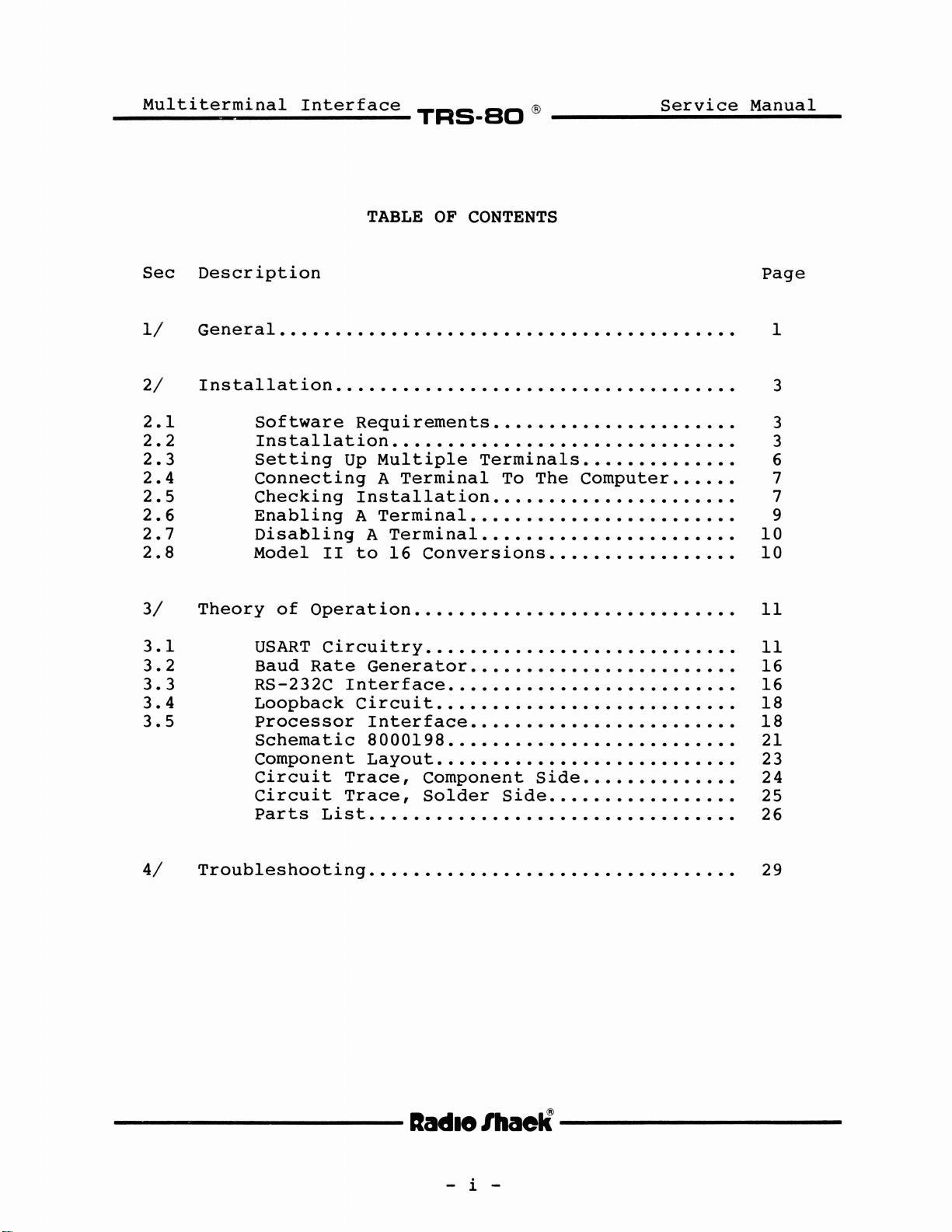
TABLE
Description
General. . . . . . . . . . . . . . . . . . . . . . . . . . . . . . . . . . . . . . . . . 1
Installation.
Software
Installation...............................
Setting
Connecting
Checking
Enabling
Disabling
Model
Theory
of
USART
Baud
RS-232c
Loopback
Processor
Schematic
Component
Circuit
Circuit
Parts
. . . . . . . . . . . . . . . . . . . . . . . . . . . . . . . . . . . 3
Requirements......................
Up
Multiple
A
Installation......................
A
Terminal........................
A
II
to
Operation.............................
Circuitry
Rate
Generator
Interface
Circuit
Interface........................
8000198
Layout
Trace,
Trace,
List.................................
OF
Terminal
Terminal
16
Conversions
..•.......................
..................•........
.......•...•..............•
Component
Solder
CONTENTS
TerminaIs..............
To
The
Computer......
Side
Side
Page
10
10
Il
Il
16
16
18
18
21
23
24
25
26
3
3
6
7
7
9
4/
Troubleshooting
----------lIadI8
lhaelÏ
- i -
29
----------
Page 4
_M_u_l_t_i_t_e_r_m_i_n_a_l_I_n_t_e_r_f_a_c_e_
TRS-SO
®
S_e_r_v_i_c_e_M_a_n_u_a_l
__
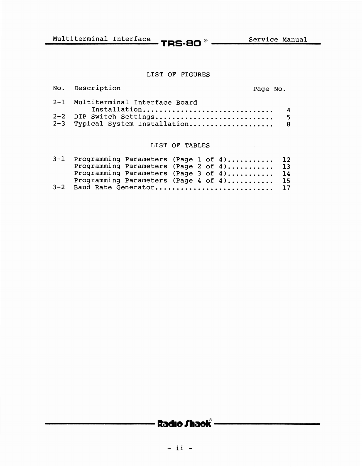
No.
2-1
2-2
2-3
3-1
3-2
Description
Multiterminal
Installation.
DIP
Switch
Typical
System
Programming
Programming
Progralnming
Programming
Baud
Rate
LIST
Interface
OF
Board
FIGURES
• • • • • • • • • • • • . • • • • • • • • • • • • • • • • • 4
Settings............................
Installation....................
LIST
Parameters
Parameters
Parameters
Parameters
Generator
OF
TABLES
(Page
(Page
(Page
(Page
••••••••••••••••••••••••••••
Page
l
of
4 ) . . . . . . • . . . .
of
2
3
4
4 ) . . • . . . . . . . .
of
4 ) . . . . . • . . . . .
of
4 ) . . • • . . • • . . .
No.
5
8
12
13
14
15
17
----------lIadI8
lhaelÏ----------
-
ii
-
Page 5
__
M_u_l_t_1_et_e_rl!Wlllm_i_n_a_l_I_n_t_e_r_f_a_c_e_
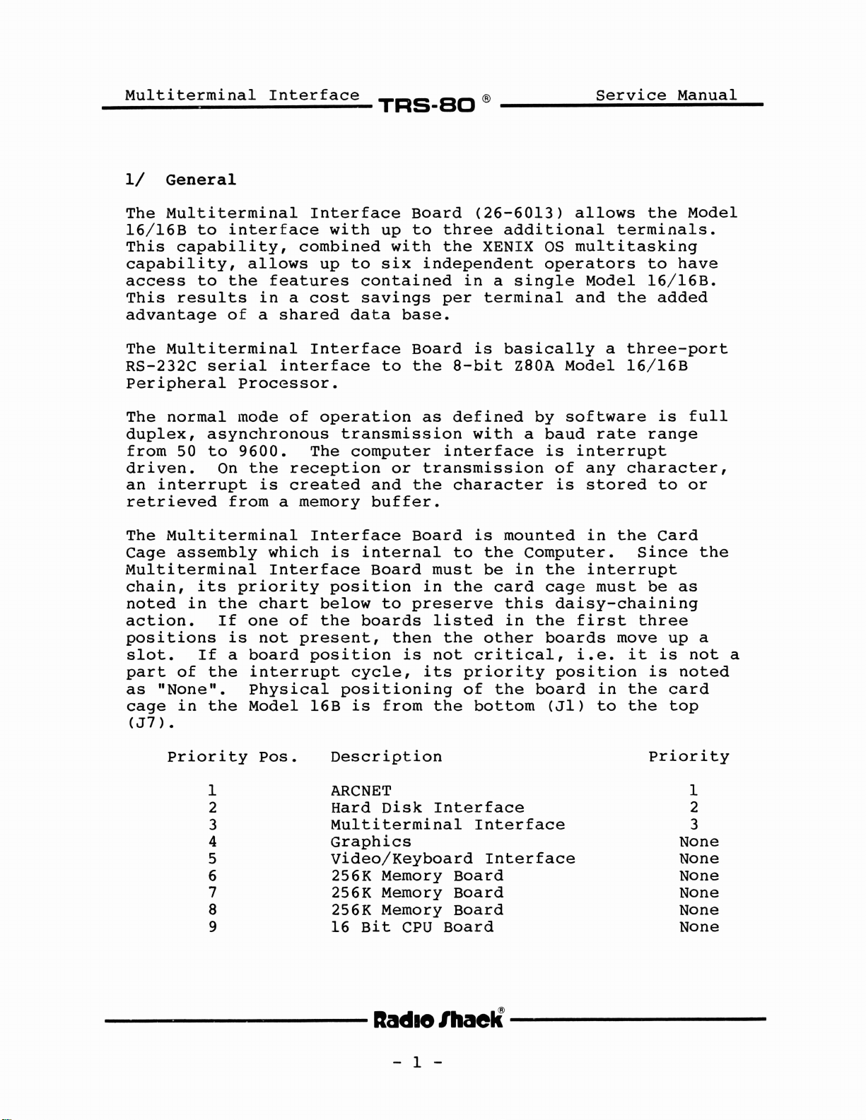
1/
General
The
Multiterminal
16/16B
This
capability,
capability,
access
This
results
advantage
The
Multiterminal
RS-232C
Peripheral
The
normal
duplex,
from
50
driven.
an
interrupt
retrieved
to
interface
allows
to
the
in
of
a
seriaI
Processor.
mode
asynchronous
to
9600.
On
the
is
from
Interface
combined
features
a
cost
shared
Interface
interface
of
The
reception
created
a
memory
with
up
to
contained
savings
data
operation
transmission
computer
and
buffer.
TRS-SO
Board
up
to
three
with
six
to
or
the
independent
per
base.
Board
the
as
interface
transmission
the
®
(26-6013)
additional
XENIX
in
a
terminal
is
basically
a-bit
defined
with
character
OS
operators
single
Z80A
by
a
baud
is
Service
al10ws
multitasking
Model
and
a
Model
software
rate
interrupt
of
any
is
stored
Manual
the
terminaIs.
to
have
16/16B.
the
added
three-port
16/16B
is
range
character,
to
Model
full
or
The
Multiterminai
Cage
assembly
Multiterminal
chain,
noted
its
in
action.
positions
slot.
part
as
cage
(J7)
If
of
"None".
in
•
the
the
Priority
1
2
3
4
5
6
7
8
9
priority
the
If
is
a
which
Interface
chart
one
of
not
board
interrupt
Physical
Model
Pos.
Interface
is
internaI
Board
position
below
the
boards
present,
position
cycle,
positioning
16B
is
Description
ARCNET
Hard
Multiterminal
Graphics
Video/Keyboard
256K
256K
256K
16
Bit
Board
in
to
preserve
then
is
its
from
Disk
Memory
Memory
Memory
CPU
is
to
the
must
be
the
listed
the
other
not
critical,
priority
of
the
bottom
Interface
Interface
Board
Board
Board
Board
mounted
Computer.
in
card
this
in
the
the
board
Interface
in
the
the
interrupt
cage
must
daisy-chaining
first
boards
i.e.
move
it
position
in
the
(JI)
to
the
Card
Since
be
three
up
is
is
card
top
priority
the
as
a
not
noted
1
2
3
None
None
None
None
None
None
a
----------lIadlo/haelÏ
---------
- l -
Page 6

Multiterminal
Interface
TRS-SO
®
S_e_r_v_i_c_e_M_a_n_u_a_l_
----------lIadlelllaell----------
- 2 -
Page 7
__
M_u_I_t_i_t_e_r_m_1_'
2/
Installation
n_a_I_I_n_t_e_r_f_a_c_e_
TRS-SO
~-'
Service
Manual
Included
installing
PCB
in
allows
terminaIs
used
Manual
2.1.
The
which
higher.
01.03.00.
If
necessary
(Catalog
a
If
necessary
(Gatalog
by
only
you
version
you
in
and
the
Model
you
to
to
aIl
for
operating
Software
current
supports
You
already
to
No.
01.03.00
do
not
to
No.
the
following
interconnecting
16
interconnect
the
computer
terminaIs.
Requirements
operating
this
must
modify
700-2066)
purchase
700-2052).
have
have
upgrade
System.
the
pages
Radio
instructions
board
the
it
Refer
XENIX
using
which
XENIX
the
Shack
so
your
XENIX
are
the
Computer.
as
many
that
to
system
is
TRS-XENIX,
system
Operating
a
software
modifies
Operating
instructions
Multiterminal
as
five
a common
the
TRS-XENIX
for
the
offered
to
a
Version
This
additiona1
data
system.
by
Version
at
System,
update
1.1
System,
01.03.00
Operator's
Radio
least
diskette
or
1.2
it
for
Interface
option
base
01.03.00
it
Shack
a
is
system
will
Core
may
version
be
or
to
be
System
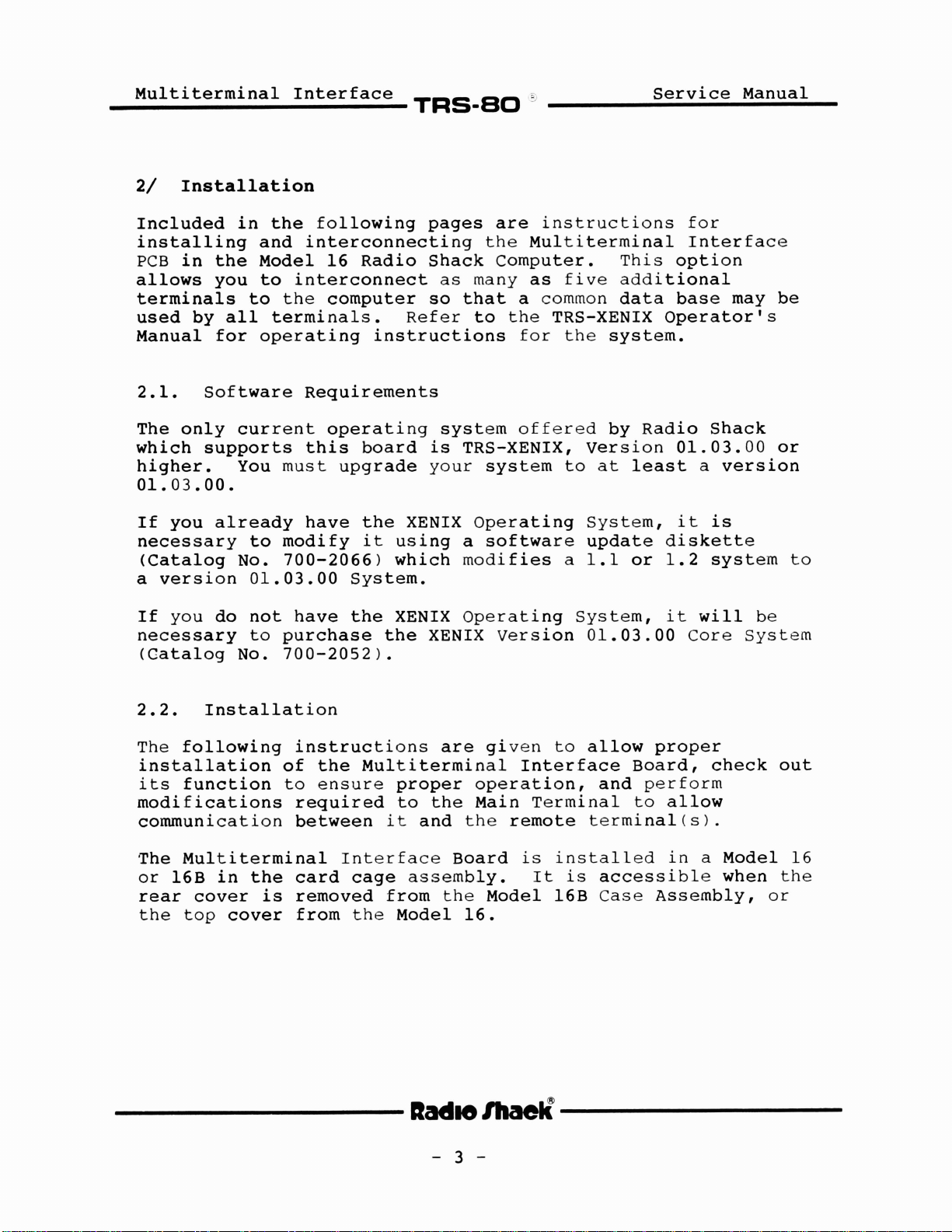
2.2.
The
installation
its
modifications
communication
The
or
rear
the
Installation
following
function
Multiterminal
16B
in
the
cover
top
cover
instructions
of
to
required
between
card
is
removed
from
the
Mu1titerminal
ensure
Interface
cage
the
proper
to
the
it
and
assemb1y.
from
Model
----------IIMIOIhaeIl----------
- 3 -
are
operation,
Main
the
Board
the
16.
given
Interface
remote
is
Model
to
allow
Terminal
termina1(s).
installed
It
is
16B
proper
Board,
and
perform
to
al10w
in
accessible
Case
Assemb1y,
check
a
Model
when
out
16
the
or
Page 8
__
M_u_l_t_1_et_e_r_m_1_
e
n_a_l__I_n_t_e_r_f_a_c_e_
TRS-SO
®
Service
Rear View
Manual
Multiterminal
Interface
Board
Rear
View
Model16
68000
CPU
16-Bit Memory
16-Bit Memory
::>
>
0
E
Q)
~
~
co
co
-e
ca ca
0
ca
0
Q)
'"C
:>
~
u
0
0
0
co
co
>
0
E
Q)
~
~
ai
cO
Q)
(J
't
Q)
~
.E
ni
c
°ê
Q)
~
:E
:1
~
~
ë
-e
::I:
~
en
ca
::>
J!
~
u
e
~
~
c
ai
0
cO
U
~
en
ë
>
Q.
Q.
0
Li:
Option
Video Board
Multiterminal Interface
Hard Disk
Figure
2-1.
----------lIadlo
Multiterminal
or
Upgraded Model 12
Interface
IlIaelÏ----------
- 4 -
Board
Installation
Page 9
Multiterrninal
Interface
~~~.~~®~~~~~_s_e_r_v_i_c_e~M_a_n_u_a_l~_
1.
Model
Model
2.
Rear
Cover
16
Turn
allow
the
access
unscrewing
rear
Insert
on
the
Multiterminal
2-1.
16B
Turn
allow
the
access
mounting
Lift
out
down.
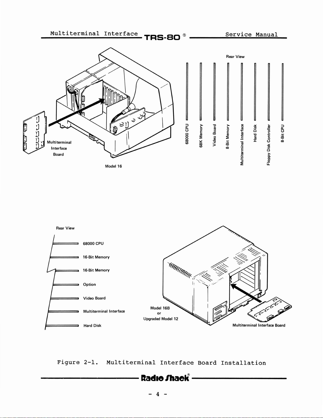
Remove
the
board
the
card
to
connector(s)
DIP
switch
noted
in
connector
Multiterminal
chain.
the
must
board
be
Therefore,
in
Removal
computer
to
the
top
computer
to
screws
on
the
card
cage
be
to
installed.
on
SI
must
Figure
slot
Interface
and
JI.
JI
if
so
the
two
cover
so
the
at
bot
holding
allow
the
2-2.
as
shown
no
that
top
the
cover.
mounting
to
gain
Interface
that
rear
the
tom
the
cover.
10wer
of
the
brackets
the
Attach
Multiterminal
be
set
for
Slide
in
board
there
The
other
must
Multiterminal
boards
rear
is
Remove
screws.
access.
PCB
as
rear
is
Remove
part
cover
of
plate
from
Multiterminal
the
cable
Interface
the
proper
the
board
Figure
must
be
2-1.
be
no
are
facing
the
Lift
noted
facing
the
the
either
into
The
in
empty
Interface
present.
you
top
up
and
in
you
two
rear
and
cover.
pull
side
Interface
end(s)
Board.
operation
the
the
interrupt
slots
to
cover
ta
Figure
ta
of
to
between
board
by
the
the
The
as
OFF
----------lIadI8
ON
S1-0N
S2-Sa -
InllJ
Figure
J1
Jumpers must
E7-E8
DIP Switch
Inl
OFF
2-2.
J2
be
El0-E11
DIP
- 5 -
J3
in place
E13-E14
Switch
Settings
Ihaell-----------
Page 10
Multiterminal
Interface
TRS-SC
®
Service
Manual
3.
2.3.
The
of
terminaIs
itself
capabilities.
The
terminaIs.
and
DT-I's
a TRS-XENIX
a
and
paragraph
other
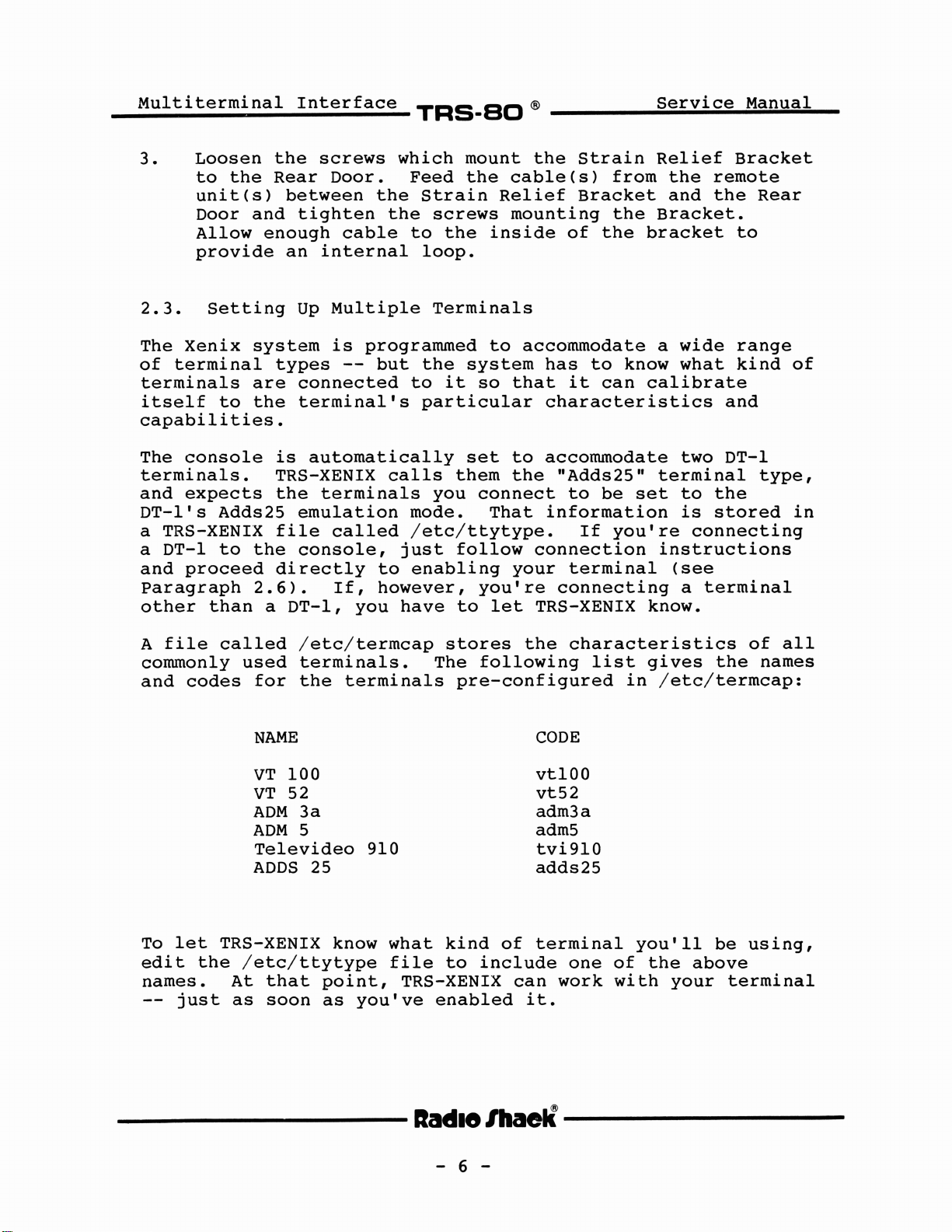
Loosen
to
unit(s)
Door
Allow
provide
Xenix
terminal
console
expects
DT-l
proceed
the
Setting
to
Adds25
to
than
the
Rear
between
and
tighten
enough
an
Up
system
types
are
connected
the
terminal's
is
automatically
TRS-XENIX
the
emulation
file
the
console,
directly
2.6).
a
DT-l,
screws
Door.
the
cable
internaI
Multiple
is
programmed
--
but
terminaIs
called
to
If,
however,
you
which
Feed
Strain
the
screws
to
the
loop.
TerminaIs
the
to
it
particular
calls
you
mode.
/etc/ttytype.
just
enabling
have
mount
the
inside
to
system
so
set
them
connect
That
follow
you're
to
let
the
cable(s)
Relief
mounting
of
accommodate
has
that
to
the
your
it
characteristics
accommodate
"Adds25"
to
information
connection
terminal
connecting
TRS-XENIX
Strain
from
Bracket
the
the
to
know
can
be
If
you're
Relief
the
and
Bracket.
bracket
a
wide
what
calibrate
two
terminal
set
to
is
connecting
instructions
(see
a
know.
Bracket
remote
the
Rear
to
range
kind
and
DT-I
type,
the
stored
terminal
of
in
A
file
commonly
and
codes
To
let
edit
names.
--
the
just
called
used
TRS-XENIX
/etc/ttytype
At
as
/etc/terrncap
terminaIs.
for
the
NAME
VT
100
VT
52
ADM
ADM
ADDS
3a
5
Televideo
that
soon
25
know
point,
as
terminaIs
910
what
file
TRS-XENIX
you've
stores
The
following
pre-configured
kind
to
enabled
of
include
can
the
characteristics
CODE
vt100
vt52
adm3a
adm5
tvi910
adds25
terminal
one
work
it.
list
gives
in
/etc/termcap:
you'll
of
the
with
above
your
of
the
be
using,
terminal
aIl
names
---------lIadlelhaell---------
- 6 -
Page 11
__
M_u_1_t_1._'
t_e_r_m_i_n_a_1_I_n_t_e_r-f-a-c-e_
TRs-aD
®
S_e_r_v_i_c_e_M_a_n_u_a_I
__
2.4.
First,
If
it
RS-232
(Cat.
1.
2.
3.
4.
If
the
RS-232
Connect
RS-232
Connect
of
Connect
Channel
If
insert
Channel.
the
Multiterminal
Connecting
check
is
cable
No.
the
the
terminal
cable
which
either
(Cat.
26-1496)
one
jack.
the
null
the
A
computer
a
assembly.
A
Terminal
connector
SeriaI
No.
for
end
of
other
modem
adapter's
or
B
of
requires
Terminator
connects
Interface
To
Channel
26-4403)
each
end
adapter.
your
the
Plug
to
terminal.
RS-232
of
male
computer.
one
pca,
The
you're
A
and
the
plug
it
into
of
Computer
using
or
B,
a
cable
cable
to
(check
any
the
you
will
you
null
to
to
either
the
unused
three
(see
for
the
will
modem
the
the
owner's
SeriaI
connectors
need
Figure
terminal.
need
adapter
terminal's
female
SeriaI
manual),
only
the
2-3)
an
plug
on
2.5.
Correct
when
XENIX
Type
Response
There
will
*
Checking
the
produce
in
disable
will
appear:
disable:
disable:
OX=one
For
Installation
installation
following
the
the
following
ttyOX
be
no
ttyOX
/etc/ttys
of
the
example,
of
commands
noted
command*:
(enter)
response
is
tty
terminaIs,
tty04.
the
Multiterminal
typed
responses.
or
already
not
updated
the
disabled
into
following
either
the
Interface
computer
error
(which
4,
5
or
message
is
OK)
6.
is
ensured
running
----------lIadI8
lhaell----------
- 7 -
Page 12

Multiterminal
Interface
~~~_~~®~~~~~S_e_r_v_1_·c_e~M_a_n_u_a_l~_
RS-232 Cable
26-4403
Terminal No. 2
T-T~
Alternate Connection
Terminal No. 6
Figure
2-3.
B
Typical
Interface
Terminal No. 5
Installation,
Board
Multiterminal Interface
Terminal No. 4
Multiterminal
PCB
-----------Iadlelllaell----------
- 8 -
Page 13

__
M_u_l_t_i_t_e_r_m_i_n_a_l_I_n_t_e_r_f_a_c_e_
TRS-SO
®
Service
Manual
Type
Response
2.6.
Before
enable
in
cat
Ihconsole
09ttyOl
09tty02
09tty04
09ttyOS
09tty06
(or
"cat
redirection)
the
/etc/ttys
(on
something
/etc/ttys"
Enabling
you
a
terminal
enable
following
terminal
A
can
use
command:
>/dev/ttyOX
OX)
similar
were
Terminal
a
terminal,
connected
ttyOI
--
typed
at
<ENTER>
(enter)
it
without
it
SeriaI
should
must
look
any
be
enabled.
Channel
the
output
A,
same
type:
To
as
if
To
For
PCB,
Then
enable
any
type:
you're
a
terminal
enable
terminaIs
enable
or
enable
or
enable
ready
connected
tty02
connected
tty04
ttyOS
tty06
to
use
<ENTER>
to
<ENTER>
<ENTER>
<ENTER>
the
at
the
terminal
SeriaI
Multiterminal
(for
to
(for
to
(for
to
Channel
terminal
JI)
terminal
J2)
terminal
J3)
with
B,
Interface
connected
connected
connected
TRS-XENIX.
type:
----------lIadI8
- 9 -
lhaelÏ
----------
Page 14

Multiterrninal
Interface
~~~_~~®
~~~~~~S~e_r_v~1_'c~e~_M_a_n~u~a_l~_
2.7.
If
for
the
terminal
(Remember:
and
the
2.8.
The
board
Disabling
you
have
any
connector
proceed
main
Model
Model
provided
to
reason,
type:
disable
thru
disable
There
to
computer
II
II
A
disconnect
be
the
disconnect
to
can
be
sorne
Terminal
sure
terminal
ttyOl
tty06
is
connector.
16
you
no
tty03)
Conversions
used
precautions
a
the
to
terminal
first
is
using,
remote
test
disable
the
are
from
and
(for
(for
to
terminal
Multiterminal
taken.
the
it.
at
SeriaI
terminal
J3)
main
Again,
the
Channel
connector
computer
check
main
A)
connected
from
Interface
There
boards
FCH-FFH.
correct
10
normal
The
board
70H-7EH
II
II/12/16/16B
cause
TRS-XENIX
VDG
of
test
with
boards.
is
that
IC27
operation
was
a
a
dual
makes
This
this,
on
software
written
for
the
a
Rev
problem
without
addressing
is
a
jumper
the
first
A
or
has
testing
ports
only
VDG
board.
of
the
MULTERM
for
ports
board.
Rev
an
older
the
jumper
problem
7CH-7FH
on
Rev
has
to
Model
for
B
VDG
video
the
be
A
and
be
installed
This
II.
the
Multiterminal
70H-7EH.
If
this
board
board
board
mentioned
or
in
early
interpreted
Rev
B
will
OR
not
TRS-XENIX
is
in
if
a
installed,
attempting
above
Model
VDG
from
affect
an
Model
as
boards.
older
on
II
VDG
ports
pin
l
the
Interface
also
to
these
uses
Model
it
will
run
To
to
older
pin
----------lIadlO
IhaelÏ
-
10
-
----------
Page 15

__
M_u_l_t_i_t_e_r_m_i_n_a_l_I_n_t_e_r_f_a_c_e_
3/
Theory
The
Multiterminal
divided
Generatori
and
Model
(5)
II
Of
into
(3)
zao
Interface.
Technical
Operation
Interface
five
parts:
RS-232C
Reference
Interface
See
TRS-SD
Board
(1)
USART
Intel
Manual,
®
can
be
circuitrYi
circuitrYi
Specification
SIO
Service
functionally
(2)
(4)
Loopbacki
a25lA
Section.
Baud
Manual
Rate
and
3.1
The
Transmitter)
which
seriaI
circuit
interface
logici
designators
3.1.1
The
transmitter
CPU,
parameter
and
specify
transmission
bits,
3.1.2
USART
USART
accomplishes
and
and
CPU
CPU
by
receiver
etc.).
Transmitter
Circuitry
(Universal
is
parallel
can
be
logici
(4)
for
Interface
Interface
and
read/write
commands
data.
the
transmission
characteristics
See
a
Medium
aIl
divided
(2)
the
Modem
the
logic
the
operations,
and
Table
Logic
Synchronous
Scale
of
the
data
USARTs
receiver
Configuration
under
into
the
Transmitter
Control
Logic
links
transmitter
mode
3-1
four
are
for
Asynchronous
Integrated
required
CPU
directions.
parts:
logici
logic.
U16,
the
-issues
(asynchronous)
(number
U17,
two
with
data,
commands,
the
programming
the
of
Receiver
Circuit
transformation
(1)
the
(3)
The
schematic
and
U19.
major
configuration/
parts
Zao
CPU.
and
reads
for
and
characters,
(MSI)
of
The
USART
CPU
the
Receiver
--
the
The
zao
status
example,
stop
parameters.
The
transmitter
stored
rate.
RDY
which
Transmission
Enable
RS-232
logic.
in
When
signal.
is
flag
signaIs
the
the
used
controlled
----------lIa«l18
serial1y
transmitter
transmitter
The
TX
to
request
is
controlled
DSR/DCD
RDY
shifts
signal
another
by
and
buffer
buffer
either
the
CTS
-
Il
out
the
character
at
the
applied
is
is
character
CPU
received
empty,
connected
internally
or
possibly
by
it
to
from
by
the
an
by
modem
lhaell----------
-
data
baud
sets
interrupt
the
the
external
clock
the
CPU.
TX
control
TX
Page 16

__
M_u_l_t_i_t_e_r_rn_l._
e
n_a_l_I_n_t_e_r_f_a_c_e_
BAUD
TRS-SO
RATE GENERATOR
®
Service
Manual
ADDRESS
70
71
72
73
CHANNEL
CHANNEL
CHANNEL2,LSB BYTE,
COMMAND WORD
COMMAND WORD
7
1
1 1 1 1
~
0
-J
-J
W
W
Z Z
z
z
~
~
::I:
~
"
t- t-
"
(.)
u
w
w
-J
..J
w
w
en en
..
....
0
0
0
0, LSB BYTE,
1, LSB BYTE,
6
N
..J
W
Z
z
~
:I:
u
t-
(.)
W
..J
w
CI)
0
~
5
t-
Z
:::>
0
U
t-
Z
w
a:
a:
:::>
:I:
"
t-
"
«
-J
0
0
1
0
~
w
a:
0
t-
w
:::>
..J
~
>
DATA
4
W
:::>
-J
~
>
a:
w
t-
z
:::>
0
"
0
«
0
..J
..
~
....
MSB
MSB
MSB
3
0
BYTE
BYTE
BYTE
1
-J
~
Z
e"
en
t-
:::>
0.
t-
:::>
0
a:
W
t-
z
:::>
0
u
2
1
w
en
-J
:::>
0.
en
:::>
0
:::>
z
t-
z
0
u
1
1
1
w
-J
u
>
U
>
t-
:::>
0
0 Z Z
'*'
Ln
w
0.
>
t-
~
t-
~
0
a:
W
t-
:::>
0
u
0
0
0
U
m
Il
~
>
a:
~
m
Il
0
Table
----------lIadI8
3-1.
Note 1:
Note 2: Counter Value ReadlWrite in
programming
Bit4,5 =0,
consecutive bytes, LSB first.
Bit
Parameters
lhaelÏ
-
12
-
0-3 =
DON'T
(page
----------
CARE
two
l
of
4)
Page 17

__
M_u_l_t_l._"
t_e_r_rn_i_n_a_l_I_n_t_e_r_f_a_c_e_
INTERRUPT CONTROLLER
TRS-SD
®
Service
Manual
ADDRESS
74
75
CHANNEL 0 CTC CONTROL/INTERRUPT VECTOR
CHANNEL 1 CTC CONTROL/INTERRUPT VECTOR
76 CHANNEL 2
77
NOT USED
CONTROL WORD:
7
w
-J
en
<t
z
w
w
1-
..J
0-
en
:>
<t
a:
~
a:
W
0
l-
Il
Z
0
6 5
a:
w
I-
Z
:>
0
U
Il
....
a:
w
~
w
0
l-
0
Il
~
0
DATA
CTC
CONTROL/INTERRUPT VECTOR
W
=>
~
<t
>
a:
W
..J
«
U
CI)
w
a:
0-
U)
Ln
N
Il
....
U)
....
Il
0
w
CJ
0
W
a:
w
e,:,
C'
a:
t::
~
U
0
-J
U
4
3
w
CI)
a:
Il
a:
....
w
e,:,
e,:,
a:
-J
l-
-J
a:
<t
LL
W
~
Il
0
~
C'
a:
1-
~
"
U
0
..J
U
Il
....
0
1-
:>
«
Il
0
2
-
Ww
1-0
>0
en~
I-a:
Zw
<t~
1--
CI) 1-
z-
o CI)
us:
wO
~-J
_..J
1-0
Il
....
LL
z
0
l-
<t
a:
w
0-
0
CI)
:>
0
=>
z
~
Z
0
u
Il
0
1
0
1
a:
0
1-
u
0
w
a:
0
>
l-
~
0-
-J
:>
0
1-
w
CI)
W
a:
....
a:
a:
a:
1-
w
Z
1-
0
~
U
Il
Il
....
Il
0
TIME CONSTANT:
E]
INTERRUPT VECTOR:
1
VECTOR
Table
----------lIadI8/haell----------
3-1.
Programming
-
13
1
1
DATA
-
~
1 1 1
1
I
1
Parameters
1
1
O
....
NM
-J-J..J..J
owwww
-zzzz
..Jzzzz
w<t<t<t<t
Z::I:::I:::I:::I:
Z U U U u·
<t
Il
Il
....o....
o
00
Il
........
::I:
U
(page
Il
B
2
y-
u
1-
U
>
en
0
w
1-
a:
W
CI)
z
-
of
L-
0
4)
Page 18

__
M_u_l_t_i_t_e_r_rn_l._
e
n_a_l_I_n_t_e_r_f
a_c_e_
TRS-SO
USART
®
Service
Manual
ADDRESS
78
7A
7C
79
78
7D
CHANNEL0,RECEIVE,
CHANNEL
CHANNEL
1, RECEIVE,
2, RECEIVE,
CHANNEL0,USART
CHANNEL
1, USART MODE
CHANNEL2,USART
MODE
7
a:
w
m
:E
::l
z
~
m
~
0
t-
CI)
1
1
.-
Il
.-
0
c
..J
~
>
z
-
Il
0
0
6 5
M
Il
.-
.-
>
~
a:
~
~
c
c
N
0
Il
0
0
.-
DATA
TRANSMIT
TRANSMIT
TRANSMIT
CHARACTER
CHARACTER
CHARACTER
MODE/COMMAND/STATUS
/COMMAND/STATUS
MODE/COMMAND/STATUS
4
0
0
.-
Il
w
>
..J
~
m
a:
~
~
z
~
w
z
>
w
t-
>
W
Il
a:
Il
~
~
.-
2
3
1
1
J:
t-
CD
C'
Il Il
z
.-
W
0
..J
a:
w
t-
(J
~
Ln
a:
~
Il Il
J:
0
(J
0
CI)
.-
.-
.........
0
.-
1
1
C
::l
<t
ma:
~O
ot-
ZO
>~
CI) LI. 0
~w
"""t-
(J~
za:
>
CI)
1
1
CD
Il
.-
0
Z
>
CI)
Il
0 0
0
0
0
X
~
Il
.-
.-
X
CD
.-
Il
.-
COMMAND
0
(J
t-
w
CI)
w
a:
Il
.-
Table
3-1.
programming
----------lIadI8/I1aell----------
-
14
a:
0
w
::l
a:
t-
CI)
t-
a:
.-
a:
a:
w
t-
w
CI)
w
a:
Il
Il
.-
Parameters
-
..J
~~
:E~
a:w
Oa:
Zm
Il
Il
0.-
w
~
w
(J
w
a:
w
..J
m
~
z
w
Il Il
.-
(page
w
::l
a:
...
a:
t-
c W
.-
3
of
t:
:E
CI)
z
a:
..J
m
~
z
.-
~
t-
w
Il
4)
Page 19

__
M_u_l_t_i_t_e_r_m_i_n_a_l_I_n_t_e_r_f_a_c_e_
TRS-aO
®
Service
Manual
ADDRESS
79,
78,
7E
70
(con't)
USART
(con't)
1
STATUS
7
W
:J
a:
....
a:
(1)
c
Il
~
6
~
«
w
a:
m
Il
ct
....
ct
c
X
a:
Il
~
LOOPBACK COMMAND
DATA
5
4
a:
0
a:
a:
w
w
~
«
a:
u-
~
z
:J
a:
a:
w
>
0
Il
~
3
a:
0
a:
a:
w
>
t:
a:
«
~
Il
~
2
>
....
~
~
w
x
....
Il
~
Il
1 0
w
:J
a:
....
>
c
a:
x
a:
Il
~
w
~
a:
....
>
c
a:
>
....
Il
~
Table
LOOP8ACK COMMAND
x
7F NOT USED
3-1.
Programming
X
1 1 1 1 1 1
X
X
Pararneters
X X X
(page
4
of
~
(.)
«
m
0-
0
0
-J
Il
~
4)
----------lIa«l18
Ihaell-----------
-
15
-
Page 20

Multiterminal
Interface
~~~.~~®
~~~~~~S~e~r~v~1~'c~e~~M~a~n~u~a~1~_
3.1.3
The
receiver
applied
multiplied
detected,
receive
ROY
signal
interrupt
CPU
to
RX
Enable
3.1.4
The
Modem
signaIs
signaIs
four
dedicated
3.2
The
three
hard-wired
applied
of
frequency.
each
different
MHz
for
3-2.
signaIs
Baud
Baud
independent
each
counter
divided
the
See
Receiver
baud
sixteen
the
buffer.
is
(the
read
Modem
the
flag
Control
05R/DCD,
DTR
and
link.
Rate
Rate
to
to
the
counter
The
baud
from
different
Intel
Logic
serially
clock
next
When a
set.
same
character.
and
Control
logic
DTR,
RTS
are
used
Generator
Generator
programmable
a
specifie
USART
is
fraction
by
the
rate
the
baud
Specification
shifts
(in
this
times).
data
reception
a
character
complete
The
RX
interrupt
Logic
handles
CT5,
is
controlled
to
U18
TX
and
fractional
CPU
frequency).
(therefore,
4
MHz
rate
seriaI
particular
When
RDY
Reception
of
and
control
is
U5ART.
RX
is
programmed
on
frequencies
the
bits
character
signal
as
the
data
the
RTS.
by
the
an
MS!
counters.
The
clocks.
portion
The
the
Z80
8253.
data
RS-232C
each
in,
operation,
"start"
are
is
applied
TX
ROY)
is
controlled
character.
The
state
the
Z80 CPU.
flow
IC
that
counter
The
of
individually
can
input
bus.
are
using
bit
stored
is
stored,
requesting
handshaking
of
of
data
consists
Each
counter
output
frequency
the
applied
have
clock
The
noted
the
it
sequence
in
to
an
by
the
These
around
is
into
a
is
2.000
BCD
values
in
is
the
the
the
source
of
is
output
clock
Table
is
RX
the
the
3.3
The
receivers
the
1488
data
purpose
the
1489
signaIs
R5-232C
R8-232c
+/-12
ICs
and
of
signaIs
ICs
have
Interface
which
Vdc
U2,
clocks
this
to
Ul,
Interface
convert
levels
U4,
and
have
capacitor
reduce
U3,
and
resistor
logic
from/to
of
the
U7.
a
U6.
The
capacitor
is
cross-coupling.
The
terminations
----------Iadlelllaell----------
-
consists
the
R8-232C.
buffers
on
to
increase
receivers
16
-
of
digital
their
to
buffers
The
which
The
for
one
logic
buffers
transmit
output.
the
receivers
the
of
rise
the
and
levels
are
The
time
control
power
the
the
are
to
of
the
Page 21

~
.......J
~
1
-
0
:il
QI
CI
=--@
t-3
PI
CT
~
(0
w
tv
.
tJj
PI
~
Q,
:;c
~
cT
(0
G1
(0
::3
(1)
t;
~
cT
0
t;
~
-1
~
~
cT
.....
cT
(0
t;
a
.....
::3
PI
r-'
H
::3
cT
(0
t;
Hl
~
()
(0
8253
BAUD
(CLOCK
1X
RATE
= 2.000
GENERATOR
MHz)
16X
64X
BAUD
RATE
50
1
75 26,667
OEC
40,000
110 18,182 4706 1,136
HEX
9C40
682B
OEC
2,500
1,667
HEX
09C4
0683
0470
OEC
625
417
284
HEX
0271
01A1
011C
II
150
13,333
3415
833
0341
208
0000
UJ
•
m
300
600
1200
2400
6,667
3,333
1,667
833
4800 417
9600
208
1A06
0005
0683
0341
01A1
0000
417
208
104
52
26
13
01A1
0000
0068
0034
001A
0000
104
52
26
13
0068
a
@
0034
001A
0000
0007
7
3
0003
en
(0
t;
<:
.....
()
(0
:s:
~
::3
~
PI
.......
Page 22

__
M_u_l_t_i_t_e_r_m_i
...
n_a_l_I_n_t_e_r_f
a_c_e_
TRS-SO
®
Service
Manual
supply
"true"
the
required
3.4
The
three
seriaI
the
DSR/DCD,
to
switches
3.5
The
control
controller
3.5.1
Loopback
loopback
seriaI
USARTs
switch
Processor
processor
voltages.
(-12
data
Address
Volts)
TXD
are
and
the
U9,
signal
and
This
state
Circuit
circuitry
channels
and
returned
CTS.
signaIs
UIO,
and
Interface
interface
circuitry,
clock
Decoder
or
"false"
if
the
without
the
This
at
U13
circuitry.
biases
signal
provides
modem
to
their
is
done
digital
are
consists
data
the
signal
(+12
external
control
switched
Volts)
is
not
a
means
complementary
before
levels.
of
an
transcei~er,
into
state
present.
to
stimulus.
signaIs
the
AlI
on/off
address
either
self-test
DTR
signaIs
RS-232
three
together.
decoder,
interrupt
to
create
The
and
interface
the
the
output
RTS
RXD,
loopback
of
The
address
addressing
receiver.
Switch
"ADDMATCH"
programmable
selects
3.5.2
The
timing
control
edge
the
3.5.3
The
output
receive
bus.
SWl,
Control
control
signal
of
chip
Data
data
from
CS*.
US.
the
selects
(or
decoder
the
Multiterminal
U21
decodes
manually
which,
logic
Signal
signal
converter
The
Z80
Transceiver
transceiver
U22,
IN).
determines
A7-A4
set,
when
timing
signaIs
to
labeled
When OUT=1,
combined
array),
Circuitry
circuitry
be
acceptable
is
selects
creates
U8,
signal
IORQ,
U23.
"OUT".
whether
Interface.
into
with
consists
U12,
converter
IOR,
Direction
the
or
one-of-eight
one
of
IOR/IOW
the
and
and
by
The
direction
individual
of
U15
IOW
the
normal
not
U24
the
line
and
delays
with
INTEL
is
contro11ed
direction
is
the
Z80
is
a
line
addresses.
outputs
in
U22
chip
receiver
loopback
the
respect
farnily
onto
is
to
be
(a
U25,
leading
to
ICs.
by
is
the
Z80
an
----------lIadI8
lhaelÎ----------
-
18
-
Page 23

__
M_u_l_t_i_t_e_r_m_i_n_a_l_I_n_t_e_r_f_a_c_e_
TRS-SO
®
Service
Manual
3.5.4
The
existing
(selectable>
single
to
3.5.5
The
from
clock
applied
version
requirements.
Interrupt
interrupt
interrupt
inform
Clock
clock
the
is
interrupt
bus
used
to
is
controller
of
the
CPU
Circuitry
circuitry
is
in
the
baud
increased
Controller
format.
each
divided
per
when
two
USART
USART
has
places:
rate
in
U20
The
are
channel.
a
USART
two
parts.
by
2
generator
amplitude
is
to
the
a Z80
TX
RDY,
ORed
needs
create
unbuffered
U18;
to
CTC
RX
together
This
service.
First,
a 2
meet
to
match
RDY
to
interrupt
the
MHz
version
the
buffered
Z80
and
create
4
clock.
CTC
the
BREAK
MHz
is
clock
is
a
used
This
----------lIadlelhaelÏ
----------
-
19
-
Page 24

Multiterminal
Interface
~~~.~~®
~~~~_S~e~r_v~i_c~e~M~a~n~u~a~l~
-----------lIadI8
lhaelÏ
-
20
-
----------
Page 25

A'7*
Je-!lD
A.'*
J.-29D----I
A.S*
Je-28D----
A14*
Je-27D----
ACl5*
J.-26D
A12*
J.-2sD----4
Ali*Je-24D----17
Ale*
J.-23D----
+5VOC
GNO
+
12VOC
-12VOC
9.1I.71,72D--r
~4,1.1,89
{
7(1,7~74,79,8e
5,6,77.78
7S.76
OAT.*Je-51
OAT
1* Je-S2<:::=> 8
OAT2
*
JI-"<:::=>----~
OAT3
*
J.-S4<=>----~
OAT4*J'-SS<=>
OATS*JI-S6<=:>
OAT6*JI-57<::>
DAT7*Je-5a<=:>
J'-
19D----15
Je-2eD----6
SYNC*
Je-IlD----
J.-2zD----13
10CYC*
RESET*
Je-67D----
CLOCK
JI-44D-----8
IEIN
J.-13D----2
lE
DUT
Je-14
SELECT
Je-43<J-2-<::}1
INTRQ*
JI-II
+SV
T
4
0 Q
5-
US
74
LS74A
~---I--+--+-+----,
r--
V---
r--
V--
,r--4
---+---18
----19
~-+_+_-t---:I~
~~-+-+--t-it-t--
~--+--+--+--t---15
"----4-+-+--+--t---17-
!..-W--+-.-----rr-~gD-
L
LJ~----------------~
~C54
1
To.luf
QI
2N3908
----
===_
J
+1
,y:.
•
20
li
~
~
13
6
U24
le
74ALS24e
......
--
22ut.
C32
+5V
uf,2S
•
16WVOC
~
2SWVOC
~
WVOC
C28
±L.C33
.,--Ie
D--~"----".~-
~I~
20
<:> 9
~
15
t4
U23
13
8303
12
OE
Cl
1-
+SV
-=
Q.
-
O.luf
.........
, l
20
1
-[>--
4
U25
Il
74AlS240
<::l
Ut6
74.7(2)
3
OË~
~
1
~
l-
+~V
1
~2
:~~~
7
.....
6~
5..,j
4
2~
l-l
L.
CS01
CS21
CS31
CS41
CSSI
OUT
~
~o
_
9~S-Cl12B
----3
12
7 2 B
H4
---1
e---~
+5V
--:::L
--:::J.-
-=-
-12V
~
1---/
2---J
3----/
4----/
5----/
(8)
6----./j
7---/
8
OUT
l"
+lllV
6 81
r-4-Cl
G2A
C
...A _
""-----3
~----4
......
-----5
-------6
----7
_
_
Jll========t=t==t==+++t=~=:tt==========F==~..-L.!...--ttt--------11tt1r1TrnnL~=~-,,-<
e~15-9
1
~14-10
2P,3-III~o--
5~12-12
U21
4~1I-13
14LSI38
5~IO-14
6P-9-15
7~7-16
ADOMATCHI
--2-
PALIOLI
.Jill
r----9
-1
r-II
l--IL'--P-12~--l.--+----++_HH--H--------__r--__,-
SWI
~_.e-.
~o--
~
0-0--
I~O--.~
~
~
~o--
pol9 CSII
~II
~17
U22
~16
828155
P-'S
POI4
P-13'''='::;';''''---''''''''
P-12-----,
L~~2
~3-
UI4
S04
ïL-----+-;t-t---12~13--+--+----
'""'-(
'~"""":L
10
5JR~E~A~0~/
__
~~--------;-_,----
WRITEI
14
16
Mtl
7 10RQI
91R~E:!8!!E!TLI
R20
12-
-vA
__
"JV,,-_1--..-:4~MHZ::::::...
18
17
1
-----+-------:::C~16;----
ï
19
r--
~1-{:»-2-
.J_-------___,r_-----_,
A.
v
UI4
Lse4
---+------H-T'---4I--
~f
~r
RI6
1.2K_
.....
---
UI4
LSCl4
3-{:»-4
RI5
~2e
]
---
.....
~S--==-----------------------------
\-12
1-11
+y5V
24
2
~~oe
26
~-01
28
Z7-
02
03
1-
04
2
OS
~
08~~3
01
16-<:
CS
CS,
CS
~
6;m
CLK
Rf
2-D
-3p>
r·
I20
L
1I
1'"
10
9~
t>
~I-f
13
ir:.
l
\ t l <
5 -
IEOHI]
iNT
12-~
lE
1
13
TReCi
23-
U20Tce
7-S
TROI
22-'--
TCI
8-S
1
TRe2
21-~
TC2
9-$
TR63
2<H
5---
~8--s
+5V
- «
f-----,
-r
R21
IOK
1
-----1
1------7
-----602
V 5
V-
V _ 3
V 2 06 IATEI
V
V
'----20
-22
JO::
-=
r-23
~}.:
l
)1
7
12
D'
01
03
4
D4~
OS
107
2l-C
ës
19
AD
AI
Jm
IATE216-
ft
UJllLW-l--~~==:::~---~--t-=f+_Hrt++t_t=t============:;====;_---
UI
~
LS"
~
L=Ûs-u---------+-t----r-n'
......
-~6
r--4~
UI5
LS32(2)
+5V
~
1
~1
24
ClK0
GATEe
OUT'
U'15
CLK115
OUT113-""'----,
CLK2
OUT
RII
:J.
IDK
9-+-.-----r-Tï
II~
10-t------,
-~-----r-;-~
14-
18-6-----+-+-..,.....,......
2
17
T
+5V
10
~
...J.....!2;!MH~I~
9-
J>
P-I-
UI2
74LS74A
.......
--___.--------_r_I--1
l
c
:>
RI2
560
CI7
l 100
pl
...----
NOTE:
IN
ALL RESISTOR VALUES
UNLESS OTHERWISE SPECIFIED.
OHMS
~b~
.l''v-
-----J---4-----+
i:Fu~
~
27 IDe
1
L...-
\ !
26
..14
RXO
DI
02
T)(o
1
+5V~
~S
r-
~~:
~6'osffi~17-Ll-----T-~-t4
v--7
06
-8
07
,
.....
~'K:B.f~~
r-+-+-t--r--13
12
--I~-+--+--r--10
21
2e-ClK
+5V
~23
t=2
278
~
~
V--
2
~5-
V--
6D5
v--
7
.....-v--
8
-
...
6--t-+-+-
......
+----Ir---
_ _
UI6
RfSb-23
DSR~22--------it----12
-
CID
RD
6TR~24-----=--""--------
fiXf
WR
fXë
RST
TXRDY
RllROY~14
BREAK
~.IUf
1
26
DO"
RXO
1
02
TXO
03
04
ffiP-17--
06
07
UI7
m~23-----+~-~+-----
Ciu':~_
m~22-""'----tr---'2
.......
-----1--12
6-~--_r_-13
6-.J--..I--+---r--
~I---f__+__t_--r__-
6-
........
-+-+--+----,--
L..L-+-+4-+-~-_+-------
'-----12
'-------13
'--------10
......
-------
1L.-
CIlS
OTRp-24------=::!....-~~-----
rm
1
0
21
2"
~~
+~V~\
1'--27
"'---28
'--1
1'--2
1'--5
1'--6
f'--7
8 07
It-<J
21
20
m
WR
m
RST
TXROY
RXRDr
ClK
BREAKH6
...
!
26 4-=
RXO
O'
DI
02
TxoL,IQ
03
04
05
ffi~17-
06
UI9
RTi~23---~~-
csu'l:~~#
~p_22-
CID
6iR
ii'6
~
WR
ftë
RST
TXRDY
~~
ClK
BREAK
1.
5
-<Ç)-15
U9
74ALS241
(6/1)
1
19
1
4------3
.....
~-------
~
__
3----4......---+--16
L
19-----+~-
UI
1489(3)
~
~
U2
1488(4)
-------
1
9
1 8
6----6~4
7
13--,
~-~
LlO
9 1
25.......,
9-......,~------------E-I"'-JJ..
1!5----l1------!
16
E9~
oY.5
..,2!7
1
-_---4......-_-1191'-__16
3 L
'9-----+~-
5:A151
1~
------rVi.--
7 N
L
J 4
1_+-
1 5
l~
-e
=!
pUll
74lS27
4 6J
14Al.S241 '2.2 K
ule
1.
(6/1)
1
---,
1 4
13
4----3~1-------
1 9
......
__f------
~>11_4,.~----6f1.4
N"-v
14
~
_
8V'0
2
12
~E=2----I~13~
+5V
14a';~3)
..
~
~
141~'4)
It>
5
-12V
l
R2
2.2
.....
------OJI-2
.-.~~~--:-----DJI-3
tl!l
(
!l!.
39
6------+-----,
3---+---+----,
-12V
r
RS
......
-------aJ2-2
-4~~~~~----------C>J2-3
8
te7i
(39~
----,
K
r---C>JI-I.7
-L
-L
.----C>J2-I,7
-
_
GNO
XMIT
RCV
JI-4
RTS
JI-S crs
JI-2e
DTR
JI-6
OSR
JI-I~
TXClK
JI-17
RXCLK
JI-8
CARRIER
OETECT
J2-4
J2-S
DATA
DATA
GNO
X"IT
DATA
RCVOATA
RTS
CTS
8~10
J2-2'
8----
Lg-<J"=!
25.......,
9-6--------
_
15
~-----lp7
14-'------2
~
3
..
~24----==-~~~-----
25-
9-6------------~
,I~
16-+--_
E12~
oê!
13
~I'
7":~241
(618)
1
19
CI:A
-----~--4~+-----
.....
--t"'---14
L
....
--.----'2
-.
I5
...
~
7
~131
L<:}II=:!
$
t
~
E_l
u_
~I
~13
---~..."
U-1-1
IJ
1
I,
16
4----
J 9
C>'~
rJ'I
......
-+__-----
c
8
ES~
8J
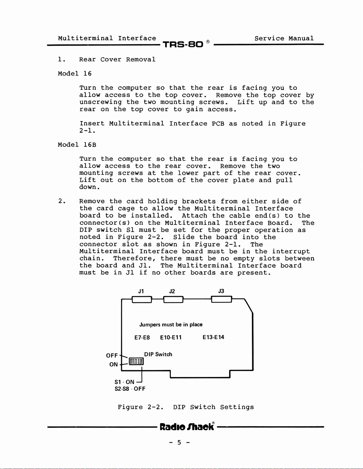
Schematic 8000198, Multiterminal Interface 26-6013
~
20
E3J'\
~E_4-___tl~12:"'1
...
13
+Sv
14.~6('1
3 1
---------..-------0
V
10
6~4
~
8~10
E6
Qoiiii----.....
4
5
~
20
12
-:-:13:;"'1
+SV
--~--+-------t
3
12
14~:(41
-1
:.
_2.2K
~----:------:------D
8
~
(
1
5ge
6
------t----.....,
---+--+------,
3
--..--+---+--
+12V
r-D
......
--",,~
DTR
J2-6
OSR
J2-15
TXCLK
J2-17
RXCLK
J2-8
8:~r~~R
-1•78ND
J3
J3-2
XMIT
J3-3
RCV
J3-4
RTS
J3-5
CTS
J3-21
DTR
J3-6
OSR
J3-15
TXClK
J3-17
RXCLK
J3-8
CARRIER
OETECT
DATA
DATA
21
Page 26

Page 27

1
--------(
~
__
M_u_1_t_i_t_e_r_m_i
U1
R2
-8-
~
R1
~
QOO
o~~
U9
-c::.-
~
...
(
Q~
J1
1
E1(X)E2
~
R13 U10 ° R12
E7~9
U16
..
n_a_l_I_n_t_e_r_f_a_c_e_
U2
~
~
00
~
E10
~
a:o
E11
E12
U17
U3
-<:::J-
R11
co
0 J2 U4 0> 0
1
r0
00Q)L....-
d
0>
R5
~O
1
'"
~
TRS-SO
------If
E3 R22
Œ)E4
~
Ou
<=J-
-c:::J-
~
{fi?
U11
U18
_1
---
R6
---(
®
U5
U12 u
E13a:o
'<t
E14
[)
Service
U6
R14
~
-e::.r-
R7
~
....
1 < (
E
15
~
U13
U19
G J3
~
000
-<:::J-
R8
~
~
1
-<:::J-
U14
L{)
[)
E5(X)E6
R9
Manua1
U7
<J
0.,
0
0R23
~
051,,-
R16~16
R15
~
U20
1
__
ua
0
U15
...JI
01
~"
~
(J
L
11F 81
1 <
TANDY CORP.
MADE
IN
U21
U.S.A.
@1983
Component
<
C31
-c=J-
Layout,
U22
0100..-
+
-c=J:
80
Mu1titerminal
1
--<Q
+
C32
-c:::r R19
U23
U24
co
C\l
U
Interface
R20
--c::::J-
< Q
0>
C\l
U
Board
0
1
1
U25
C33+-c=J-
26-6013
0
Ct)
ü
0
~
c::::::=>
C26
R21
--c::::J-
U26
--.J
REV
2
-
---------lIa«l18/I1aell---------
- 23 -
Page 28

__
M_u_l_t_i_t_e_r_m_i_n_a_1_I_n_t_e_r_f_a_c_e_
TRS-SO
®
Service
Manua1
Circuit
Trace
Board
1700230,
26-6013,
----------lIadI8/I1aelÏ----------
-
Mu1titerrninal
Component
24
-
Interface
Side
Page 29

Multiterminal
-----------
Interface
TRS-SO
®
Service
Manual
Circuit
Trace
Board
1700230,
26-6013,
---------lIadlo/haell---------
-
Multiterminal
Solder
25
-
Interface
Side
Page 30

Multiterminal
Interface
~~~.~~
®
~~~~~S_e_r_v_i_c_e~M_a_n_u_a_l~_
Parts
Multiterminal
Item
List
Sym
Cl
C2
C3
C4
CS
C6
C7
C8
C9
CIO
CIl
C12
C13
C14
C15
C16
C17
C18
C19
C20
C21
C22
C23
C24
C25
C26
C27
C28
C29
C30
C31
C32
C33
C34
Interface
Description
Capacitor,
Capacitor,
Capacitor,
Capacitor,
Capacitor,
Capacitor,
Capacitor,
Capacitor,
Capacitor,
Capacitor,
Capacitor,
Capacitor,
Capacitor,
Capacitor,
Capacitor,
Capacitor,
Capacitor,
Capacitor,
Capacitor,
Capacitor,
Capacitor,
Capacitor,
Capacitor,
Capacitor,
Capacitor,
Capacitor,
Capacitor,
Capacitor,
Capacitor,
Capacitor,
Capacitor,
Capacitor,
Capacitor,
Capacitor,
26-6013
.1
mfd,SOV
390
390
.1
mfd,
.1
mfd,
.1
mfd,
390
390
.1
mfd,
.1
mfd,
.1
mfd,
390
390
.1
mfd,
.1
mfd,
15
pfd,
100
.1
mfd,
.1
mfd,
.1
mfd,
.1
mfd,
.1
mfd,
.1
mfd,
.1
mfd,
.1
mfd,
.1
mfd,
.1
mfd,
.1
mfd,
.1
mfd,
.1
mfd,
10
mfd,
10
mfd,
22
mfd,
.1
mfd,
pfd,
pfd,
pfd,
pfd,
pfd,
pfd,
pfd,
SOV
SOV
SOV
SOV
SOV
SOV
SOV
SOV
SOV
50V
50V C
50V
50V
50V
50V
50V
50V
50V
50V
SOV
SOV
50V
50V
50V
50V
SOV
SOV
50V
SOV
25V
25V
16V
50V
Axial
C
C
Axial
Axial
Axial
C
C
Axial
Axial
Axial
C
Axial
Axial
Cer
Cer
Axial
Axial
Axial
Axial
Axial
Axial
Axial
Axial
Axial
Axial
Axial
Axial
Axial
E1ec
E1ec
E1ec
Axial
Disk
Disk
Disk
Disk
Disk
Disk
Disk
Disk
Axial
Axial
Axial
Part
8374104
8301394
8301394
8374104
8374104
8374104
8301394
8301394
8374104
8374104
8374104
8301394
8301394
8374104
8374104
8300154
8301103
8374104
8374104
8374104
8374104
8374104
8374104
8374104
8374104
8374104
8374104
8374104
8374104
8374104
8316102
8316102
8316221
8374104
No.
QI
RI
R2
R3
R4
R5
Transistor,
Resistor,
Resistor,
Resistor,
Resistor,
Resistor,
2N3906
2.2
2.2
2.2
2.2
2.2
lIadlO
kohm,
kohm,
kohm,
kohm,
kohm,
-
26
1/4W
1/4W
1/4W
1/4W
1/4W
lllaelÏ
-
5%
5%
5%
5%
S%
8100906
8207222
8207222
8207222
8207222
8207222
Page 31

__
M_u_1_t_i_t_e_r_m_i_n_a_1_I_n_t_e_r_f_a_c_e_
TRS-SO
®
S_e_r_v_l._ec_e_M_a_n_u_a_1
__
Parts
Mu1titermina1
Item
List
Sym
R6
R7
R8
R9
RIO
Rll
R12
R13
R14
R15
R16
R17
R18
R19
R20
R21
R22
R23
(cont)
Interface
Description
Resistor,
Resistor,
Resistor,
Resistor,
Resistor,
Resistor,
Resistor,
Resistor,
Resistor,
Resistor,
Resistor,
N.A.
Resistor,
Resistor,
Resistor,
Resistor,
Resistor,
Resistor,
26-6013
2.2
2.2
2.2
2.2
2.2
2.2
560
2.2
2.2
220
1.2
4.7
10
56
4.7
2.2
2.2
kohm,
kohm,
kohm,
kohm,
kohm,
kohm,
ohm,
kohm,
kohm,
ohm,
kohm,
kohm,
kohm,
ohm,
kohm,
kohm,
kohm,
1/4W
1/4W
1/4W
1/4W
1/4W
1/4W
1/4W
1/4
1/4W
1/4W
1/4W
1/4W
1/4W
1/4W
1/4W
1/4W
1/4W
5%
5%
5%
5%
5%
5%
5%
5%
5%
5%
5%
5%
5%
5%
5%
5%
5%
Part
8207222
8207222
8207222
8207222
8207222
8207222
8207156
8207222
8207222
8207122
8207212
8207247
8207310
8207056
8207247
8207222
8207222
No.
SWI
Ul
U2
U3
U4
U5
U6
U7
U8
U9
U10
Ull
U12
U13
U14
U15
U16
017
U18
U19
U20
U21
Switch,
IC,
MC1489,
IC,
MC1488,
IC,
MC1489,
IC,
MC1488,
IC,
74LS74,
IC,
MC1489,
IC,
MC1488,
IC,
74LSOO,
IC,
74ALS241,
IC,
74ALS241,
IC,
74LS27,
IC,
74LS74,
IC,
74ALS241,
IC,
74LS04,
IC,
74LS32,
IC,
8251A,
IC,
8251A,
IC,
8253,
IC,
8251A,
IC,
Z8430A,
IC,
74LS138,
SPST
Counter
DIP
Line
Line
Line
Line
Dual
Line
Line
Quad
Octal
Octal
Triple
Dual
Octal
Hex
Quad
USART
USART
USART
CTC
Decoder
8
Pos
Receiver
Driver
Receiver
Driver
Flip
Receiver
Driver
2-In
Buffer
Buffer
3-In
Flip
Buffer
Inverter
2-In
Flop
NAND
NOR
Flop
AND
8489004
8050189
8050188
8050189
8050188
8020074
8050189
8050188
8020000
8025241
8025241
8020027
8020074
8025241
8020004
8020032
8040251
8040251
8041253
8040251
8047882
8020138
---------lIadle/liaell---------
-
27
-
Page 32

__
M_u_1_t_i_t_e..r_m_i_n_a_1_I_n_t_e_r_f_a_c_e_
TRS-SO
®
S_e_rv_ic_e_M_a_n_u_a_l
__
Parts
Mu1titermina1
Item
1
2
3 2
4 1
5
6 3
List
Sym
U22
U23
U24
U25
U26
1
15
4
(cont)
Interface
Description
IC,
82S153
8303,
IC,
IC,
74ALS240,
IC,
74ALS244,
IC,
7407,
PCB
Logic
Pin,
Socket,
Socket,
Socket,
Connector,
Staking
U19,20)
26-6013
Transceiver
Hex
Board
20
Pin
24
Pin
28
Pin
Rt
Octal
Octal
Buffer
DIP(U22,23)
DIP
DIP
Angle
Buffer
Buffer
(U18)
(U16,17
(J1-3)
Part
8040153
8060303
8025240
8025244
8000007
8709410
8529014
8509009
8509001
8509007
8519109
No.
----------lIadlo
IhaelÏ----------
-
28
-
Page 33

Multiterminal
-----------
4/
Troubleshooting
Interface
TRS-BO
Service
®
Manual
Correct
when
XENIX
Type
Response
There
will
Type
Response
the
in
disable
appear:
disable:
disable:
in
cat
lhconsole
09ttyOl
09tty02
09tty04
09ttyOS
09tty06
installation
following
produce
the
will
the
/etc/ttys
the
following
ttyOX
be
no
ttyOX
/etc/ttys
following
of
commands
noted
command*:
(enter)
response
is
already
not
command:
>/dev/ttyOX
the
Multiterminal
typed
responses.
of
the
disabled
updated
(enter)
into
following
Interface
the
(which
computer
error
is
is
running
message
OK)
ensured
(or
something
if
redirection)
*
OX=one
"cat
For
/etc/ttys"
of
example,
-----------lIadI8
the
similar
tty
tty04.
--
were
terminaIs,
-
typed
29
it
should
lhaelÏ
-
without
either
look
4,
any
S
the
or
----------
same
output
6.
as
Page 34

Multiterminal
Interface
~~~_~~®
~~~~~Se~r~v~i~c~e~M~a~n~u~a~l~
----------lIadI8
lhaelÏ
-
30
-
----------
Page 35

Page 36

RADIO SHACK, A DIVISION OF TANDY CORPORATION
U.S.A.: FORT WORTH, TEXAS 76102
CANADA: BARRIE, ONTARIO L4M 4W5
TANDY CORPORATION
91
MOUNT
AUSTRALIA
KURRAJONG
DRUITT.
N.S.W.
AVENUE
2770
PARC
BELGIUM
INDUSTRIELDENANINNE
5140
NANINNE
BILSTON
WEST
U.
K.
ROAD
WEDNESBURY
MIDLANDS
WS10
7JN
MS-2606013-1083
PRINTEDINU.S.A.
 Loading...