

Page 1

Page 2
DMP
135 Dot-Matrix Printer User's Guide
©
1990
Tandy Corporation.
All
Rights Reserved.
Reproduction
or
useofany portion
of
this manual, without
express written permission from Tandy
Corporation.isprohib-
ited. While reasonable efforts have been made in
the
preparation
of
this manual to assure its accuracy,
Tandy
Corporation
assumes
no
liability resulting from any
errorsinor
omissions from this
manual,
or
from
the
liseofthe information contained herein.
Tandy and Radio Shack
are
registered
trademarks
of
Tandy
Corporation.
MS-DOS
is a
n=gist~red
trademark.
of
Microsoft Corporation.
IBM
is
a registered trademark
of
International
Business Machines. Corp.
EPSOll
is
a registered trademark
of
Epson America. Inc.
10
9 8 7 6 5 4 3 2
Note:
You
must
use a shielded cable
when
connecting
this
device.
For
your
own
protection,
we
urge
youtorecord the serial
number
of
this
unit
in the
sp~ce
provided.
You
will
find
the
serial
number
on the
bottom
of
the unit.
Serial
Number
_
Page 3
Contents
.....................................
........................•............•.
...................................
.........................................••
1
3
3
3
4
6
7
9
12
14
18
23
25
27
28
29
29
29
30
33
35
37
39
..........................
............................................................
.................................................
Loading Paper
..
Ill
..
Paper·Park Function
..
Adjusting
the
Print
Head
Power-Up
Sequence
Self Test
Choosing a Location
..
Connecting the Printer
..
Installing
the
Fanfold
Paper
Guide
............•
Installing
the
Paper
Rack
Installing
the
Ribbon Cassette
Selecting
the
Printer
Driver in Your
Software.
Control Panel
..
About
the
Printer
Getting
Started
Unpacking
the
Printer
Hex
Dump Function
..
Ready
to
Print
Printing Applications
Setting
the
Print
Function
(DIP)
Switches .
Setting
the
Character
Pitch
Setting
the
Margins
Setting
the
NLQ
Font
.•.....••..............•......•.•.
Care
and
Maintenance
Index
................••......................................
43
Page 4

Page 5

About the Printer
The
Tandy DMP
135
Dot-Matrix Printer
is
a high-density, dot-matrix
printer that can print
in
a variety of type styles.
It
prints:
• Proportionally spaced characters
• Monospaced characters (standard, condensed, and compressed)
• NLQ (near-letter-quality) correspondence characters
• Italic characters (Epson mode only)
• Superscript/Subscript
• Graphics
Control codes program the printer to print special enhancements (italic,
bold, and so on), set character type,
or
adjust line feed and spacing. You
can select either the I
BM
or Epson control code set. When you select the
IBM code set, the printer emulates the IBM Proprinter
II
(the factory de-
fault setting).
The
Epson code set emulates the Epson FX-850 printer.
By
selecting the appropriate operation mode, you can use the printer with
MS-DOS-compatible systems without code conversion and get the same
results
as
you would with an IBM ProprinterIIor
Epson FX-850. For de-
tails, see "Setting the Print Function
(DIP)
Switches."'
A character set
is
a specific grouping of letters, numbers, and special sym-
bols that you can print on your printer.
The
DMP
135
has
five
character
sets. Refer to the
OM
P /35 Dot-Matrix Printer Technical Reference
manual to
see
the character
sets
named below.
In
IBM mode:
• IBM Character Set 1
• IBM Character Set 2
• IBM All Character Set
In
Epson mode:
• Italic Character Set
• Graphic Character Set
You
can use two types of
paper
with the printer:
• Tractor-fed, 4.5- to lO-inch computer fanfold
paper
with guide holes
• Friction-fed, single-sheet typewriter paper
Page 6
About
the Priuter
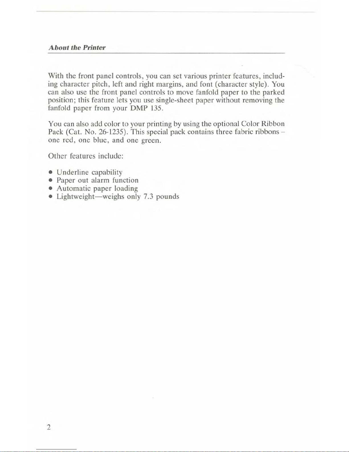
With the front panel controls, you can set various printer features. including character pitch, left and right margins, and font (character style). You
can also use the front panel controlstomove fanfold
paper
to the parked
position; this feature lets you use single-sheet
paper
without removing the
fanfold
paper
from your DMP 135.
You can also add color to your printing
by
using the optional Color Ribbon
Pack (Cat. No. 26-1235). This special pack contains three fabric
ribbons-
one
red,
one
blue,
and
one
green.
Other
features include:
• Underline capability
• Paper out alarm function
• Automatic
paper
loading
•
Lightweight-weighs
only 7.3 pounds
2
Page 7
Getting Started
Unpacking the Printer
Carefully unpack the printer.
Be
suretolocate
the
ribbon,
the
paper
rack,
the
fanfold
paper
guide,
and
both manuals.
Keep
the
empty
box
and
pack-
ing material if
you
ever
heed
to
store or move the printer. Remove the
tape from the top cover
and
open the cover. Then, remove the twist tie
securing
the
paper
bail
to
the
platen
and
close
the
cover.
Choosing a Location
When
you
choose
a location for your printer,
be
sure
to
consider the
fOllowing:
• The work surface. Place the printer
on
a sturdy surface.
•
The
length
of
the
printer
cable. This
determines
the
distance from
the
computer
that
you can place
the
printer.
• Space for paper. Be sure
to
leave enough room for a
smooth
flow
of
fanfold
paper.
• Noise generation.
Do
not place the printer near electrical noise
generators,
such
as
refrigerators or industrial equipment.
/
3
Page 8
GellingStarted
Connecting the Printer
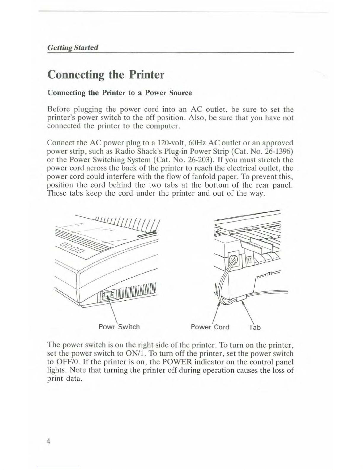
Connecting the Printer to a Power Source
Before plugging the power cord into an
AC
outlet, be sure
to
set the
printer's power switch to the
off
position. Also, be sure that you have not
connected the printer
to
the computer.
Connect the
AC
power plugtoa 120-volt, 60Hz
AC
outletoran approved
power strip, such as Radio Shack's Plug-in Power Strip (Cat. No. 26-1396)
or
the Power Switching System (Cat. No. 26-203).Ifyou must stretch the
power cord across the backofthe printer to reach the electrical outlet, the
power cord could interfere with the flow
of
fanfold paper. To prevent this,
position the cord behind the two tabs at the bottom
of
the rear panel.
These tabs keep the cord under the printer and out
of
the way.
Powr Switch
-
Power Cord
Tab
The
power switchison the right sideofthe
printer. To turn on the printer,
set the power switch to
ON/I.
To turn off the printer, set the power switch
to OFF/D.Ifthe printerison,
the
POWER
indicator on the control panel
lights. Note that turning the printer off during operation causes the loss
of
print data.
4
Page 9
Connecting the Printer
Connecting
the
Printer
to Your
Computer
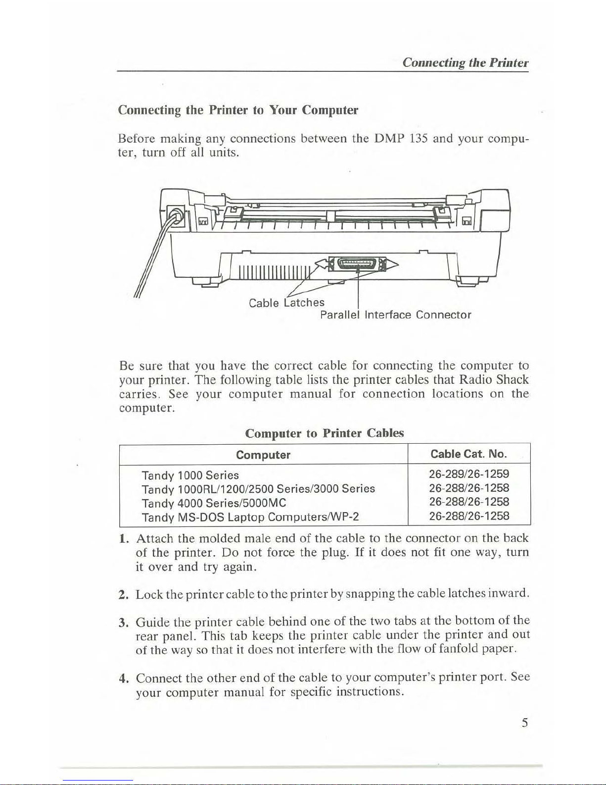
Before making any connections between the OMP
135
and your compu-
ter, turn off all units.
Cable Latches
Parallel Interface Connector
Be sure that you have the correct cable for connecting the
computer
to
your printer.
The
following table lists the printer cables that Radio Shack
carries.
See
your computer manual for
connection
locations
on
the
computer.
Computer
to
Printer
Cables
Computer
Cable Cat.
No.
Tandy 1000 Series
26-289/26-1259
Tandy 1000RU1200/2500 Series/3000 Series
26-288/26-1258
Tandy 4000 Series/5000MC
26-288/26-1258
Tandy MS-DOS Laptop ComputerslWP-2
26-288/26-1258
1. Attach the molded male
endofthe cable to the connector on the back
of
the printer.
Do
not force the plug.
If
it does not fit
one
way, turn
it over and try again.
2. Lock the printercable
to
the printer by snapping the cable latches inward.
3.
Guide
the printer cable behind
oneofthe two tabsatthe bottomofthe
rear panel. This tab keeps the printer cable
under
the printer and
out
of
the way so that it does not interfere with the flowoffanfold paper.
4. Connect the
other
endofthe cable to your
computer's
printer port. See
your computer manual for specific instructions.
5
Page 10
Get/ing
Slarted
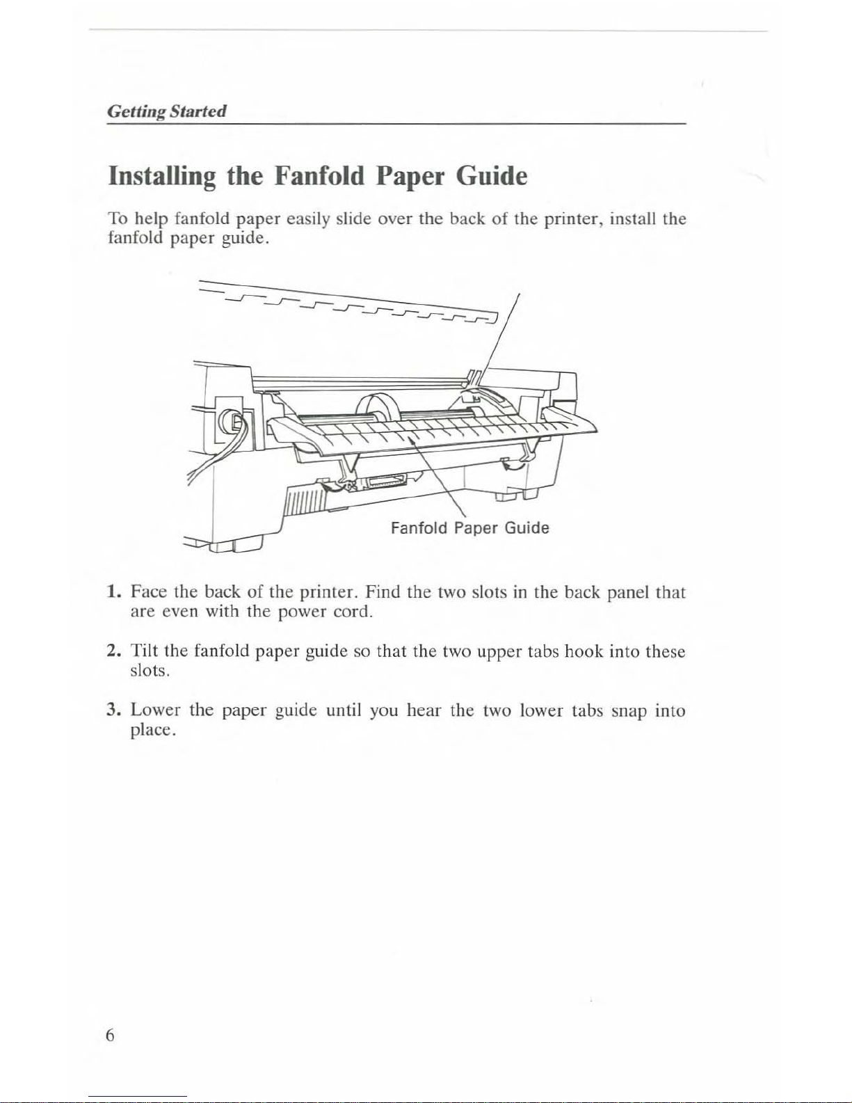
Installing the Fanfold Paper Guide
To help fanfold paper easily slide over the back of the printer, install the
fanfold paper guide.
Fanfold Paper Guide
1. Face the back
of
the printer. Find the two slots
in
the back panel that
are even with
the
power cord.
2. Tilt the fanfold paper guide so that the two upper tabs hook into these
slots.
3. Lower the
paper
guide until you hear the two lower tabs snap into
place.
6
Page 11
Illstallillg tile Paper
Rack
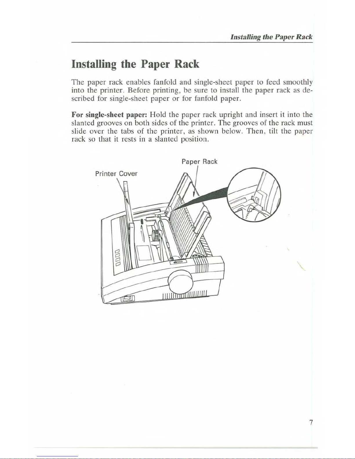
Installing the Paper Rack
The
paper rack enables fanfold and single-sheet
paper
to feed smoothly
into the printer. Before printing, be sure to install the paper rack as described for single-sheet paper
or
for fanfold paper.
For single-sheet paper: Hold the paper rack upright and insert
it
into the
slanted grooves on both sides of the printer.
The
grooves of the rack must
slide over the tabs of the printer,
as
shown below.
Then,
tilt the paper
rack so that
it
rests
ina
slanted posilion.
Paper
Rack
7
Page 12
GettingStarted
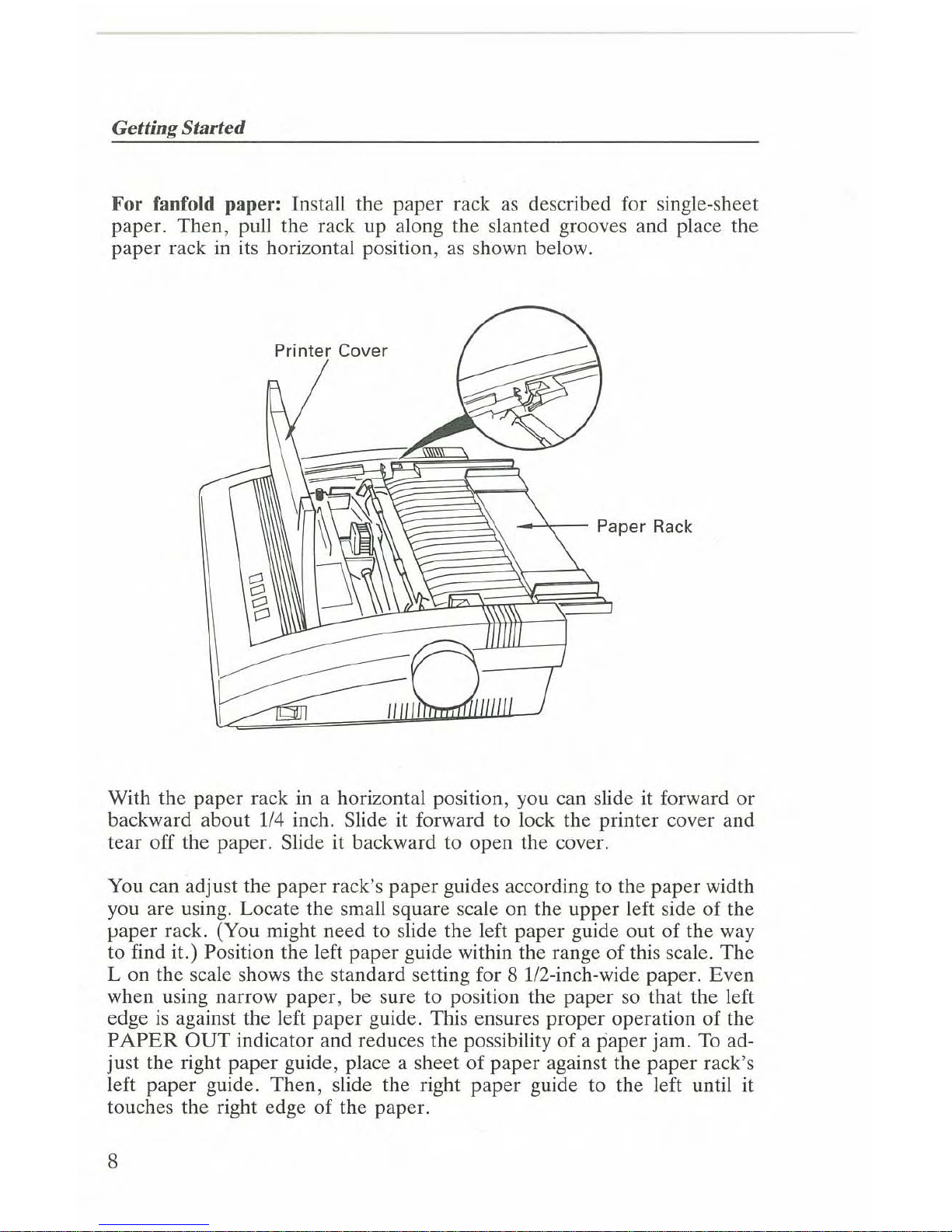
For fanfold
paper:
Install the paper rack
as
described for single-sheet
paper. Then, pull the rack up along the slanted grooves and place the
paper rack
in
its horizontal position,
as
shown below.
Printer
Cover
~",,-
Paper
Rack
With the paper rack
in
a horizontal position, you can slideitforward or
backward about
1/4
inch. Slideitforward to lock the printer cover and
tear off the paper. Slide
it
backward to open the cover.
You
can adjust the paper rack's paper guides according to the paper width
you are using. Locate the small square scale on the upper left side of the
paper rack. (You might need
to
slide the left paper guide out
of
the way
to find it.) Position the left paper guide within the range
of
this scale. The
L on the scale shows the standard setting for 8 1/2-inch-wide paper. Even
when using narrow paper, be sure to position the paper so that the left
edge
is
against the left paper guide. This ensures proper operation of the
PAPER
OUT
indicator and reduces the possibility of a paper jam.
To
ad-
just the right paper guide, place a sheet
of
paper against the paper rack's
left paper guide. Then, slide the right paper guide to the left until
it
touches the right edge of the paper.
8
Page 13
Installing the Ribbon Cassette
Installing the Ribbon Cassette
If
you have already installed the sample ribbon cassette included with your
printer, be sure that you correctly threaded the ribbon between the ribbon
mask and the print head.
If
you have not yet installed the ribbon cassette
or
if you need to replace
an old ribbon, follow this procedure.
1. Turn off the printer.
Note: When you turn off the printer, it loses any information
stored
in
the buffer.
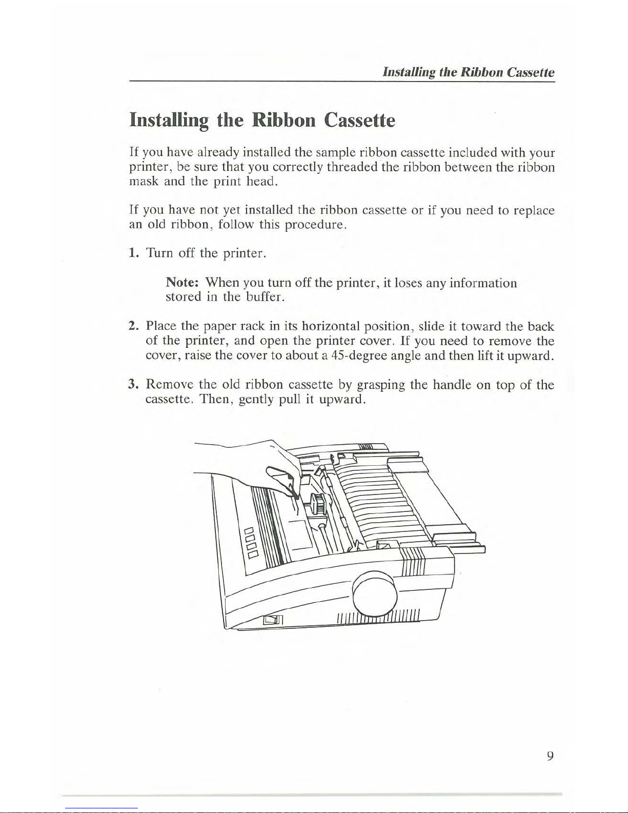
2. Place the
paper
rackinits horizontal position, slide it toward the back
of
the printer, and open the printer cover.Ifyou need to remove the
cover, raise the cover to about a 45-degree angle and then lift it upward.
3. Remove the old ribbon cassette by grasping the handle on top
of
the
cassette.
Then,
gently pull it upward.
9
Page 14
Gel/ing Started
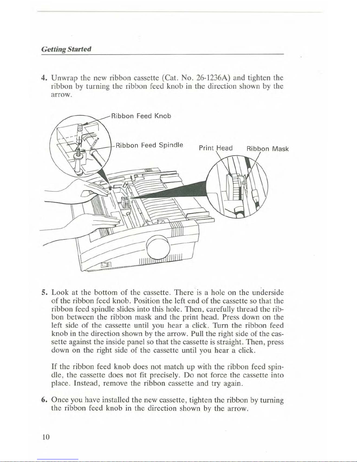
4. Unwrap the new ribbon cassette (Cat. No. 26-l236A) and tighten the
ribbon
by
turning the ribbon feed knobinthe direction shown
by
the
arrow.
Ribbon Feed Knob
~~~~_rRibbon
Feed Spindle
5. Look at the bottom of the cassette. Thereisa hole on the underside
of the ribbon feed knob. Position the left end of the cassette so that the
ribbon feed spindle slides into this hole. Then, carefully thread the ribbon between the ribbon mask and the print head. Press down on the
left side
of
the cassette until you hear a click. Turn the ribbon feed
knob
in
the direction shown
by
the arrow. Pull the right sideofthe cas-
sette against the inside panel so that the cassette
is
straight. Then, press
down on the right side of the cassette until you hear a click.
If the ribbon feed knob does not match up with the ribbon feed spin-
dle, the cassette does not fit precisely.
Do
not force the cassette into
place. Instead, remove the ribbon cassette and try again.
6. Once you have installed the new cassette, tighten the ribbon
by
turning
the ribbon feed knob
in
the direction shown
by
the arrow.
10
Page 15
Installing the Ribbon Cassette
7.
If
you removed the printer cover, replace it by holding itatabout
a 45-
degree
angle. Slide the groovesinthe printer cover
over
the
tabs on the
printer. Then, lower the printer cover
to
its
closed
position.
8. Slide the
paper
rack forward to lock the printer cover.
Caution: Printing without ribbon
or
paper
can damage the
print head
or
the platen.
11
Page 16
GettingStarted
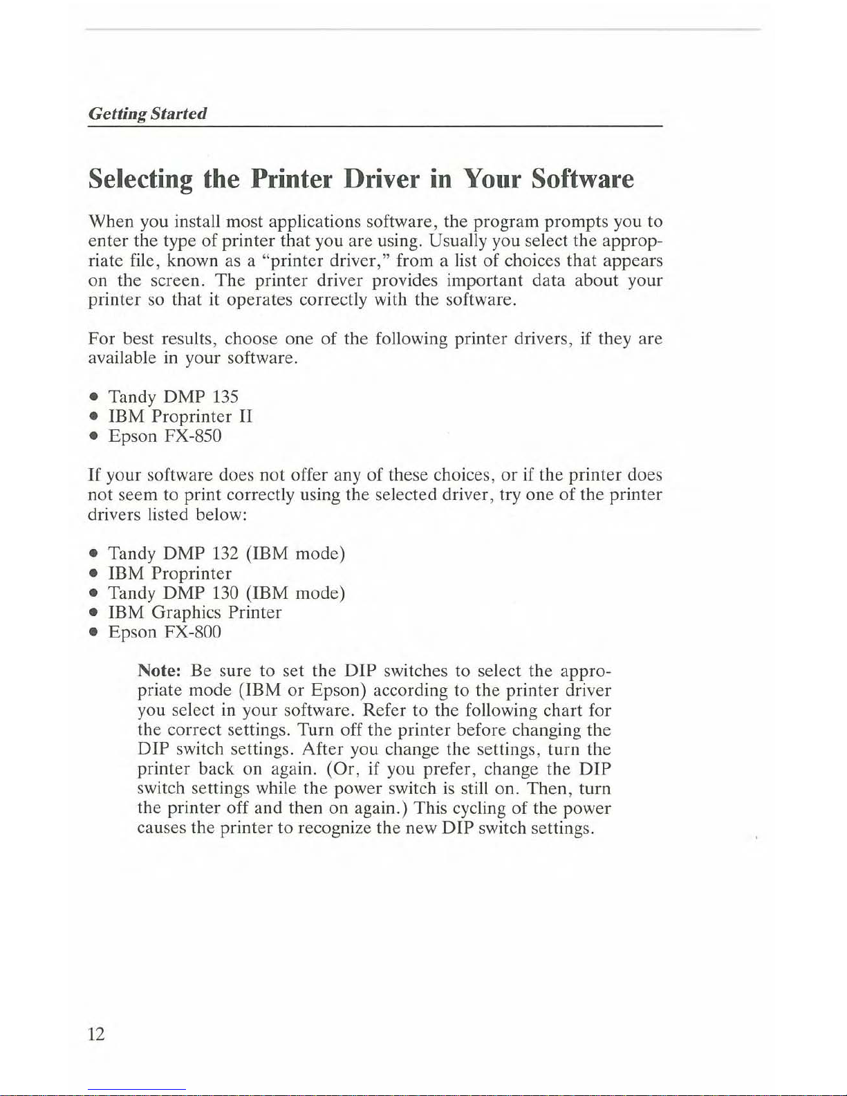
Selecting the Printer Driver
in
Your Software
When you install most applications software, the program prompts you to
enter the type
of
printer that you are using. Usually you select the approp-
riate file, known as a "printer driver," from a list of choices that appears
on the screen. The printer driver provides important data about your
printer so that
it
operates correctly with the software.
For best results, choose one
of
the following printer drivers,ifthey are
available
in
your software.
• Tandy
DMP
135
• IBM Proprinter II
• Epson FX-850
If
your software does not offer any of these choices, orifthe printer does
not seem to print correctly using the selected driver, try one
of
the printer
drivers listed below:
• Tandy DMP
132
(IBM mode)
• IBM Proprinter
• Tandy DMP
130
(IBM mode)
• IBM Graphics Printer
• Epson FX-800
Note: Be sure to set the DIP switches to select the appropriate mode (IBM or Epson) according to the printer driver
you select
in
your software. Refer to the following chart for
the correct settings. Turn off the printer before changing the
DIP switch settings. After you change the settings, turn the
printer back on again. (Or, if you prefer, change the
DIP
switch settings while the power switchisstill on. Then, turn
the printer off and then on again.) This cycling of the power
causes the printer to recognize the new
DIP
switch settings.
12
Page 17

Printer Driver
Tandy DMP 135
IBM Proprinter
II
Epson FX-850
Tandy DMP 132 (IBM mode)
IBM Proprinter
Tandy DMP 130 (IBM
model
IBM Graphics Printer
Epson FX-800
Selecting the Printer Driyerin Your Software
Set
DIP
Switch
To
IBM emulation or Epson emulation,ascalled
for
by the printer driver
IBM emulation
Epson emulation
IBM
emulation
IBM
emulation
·IBM emulation
IBM emulation
Epson emulation
If
you do not get the proper results when you print, be sure that you have installed
your software correctly.Ifyou
still have problems, contact your software supplier
for further instructions.
13
Page 18

Getting
Started
Control Panel
You can
control
many
of
the
printer
functions directly from
the
DMP
135's
control
panel,
which consistsoffour
keypad
controls
and
four
LED
indicators.
FINE
•
NLQ
V-LINE
HSD.
ON/OFF
LINE
••••
.POWER
•
PAPER
OUT
SET
Keypad Controls
.....
[ON/OFF LINE I PITCH I
MARGIN]-sets
the
printer
to
on
line
or
off
line.
To
enter
the
pitch-set/margin-set
mode,
press
and
hold this
button
for
one
second
while
the
printerison
line.
The printer goes off line when a paper empty error occurs.
To
continue
printing
when
this
happens,
press this
button.
The
printer
goes
on
line
and
prints
one
more
line;
then,
it stops
and
goes
off
line again.Ifthe
printer
buffer contains
no
data when
you
attempt
to
print one more line, the
printer
stays on line until you
input
one
line
of
data
to
the
printer.
During
the self
test,
press this
button
to
temporarily
stop
the
test. Press
it again
to
resume
the
self test.
14
Page 19

Control Panel
[HSD ILF/FF
1--->
I-sets
or
cancels the high-speed-draft (HSD) mode
in
on-line mode. When you set the HSD mode, the printer beeps twice.
When you cancel the HSD mode, the printer beeps once.Ifthereisdata
in
the printer buffer, the printer
will
print the buffer contents before you
can set
or
cancel the HSD mode.
In off-line mode, press this button to advance the
paper
one
line. Press
and hold the button to begin a form feed.
In the pitch-set, margin-set, and font-set modes, press this button to move
the print head to the right.
To begin the self test, press this button while turning on the printer.
Notes:
• To select the super-speed-draft (SSD) mode, use the pitch-set mode.
•
In
HSD mode, the
NLQ
fontisnot available.
The
NLQ
indicator lights
when you select the
NLQ
font, but printinginHSD modeisalways
in
the draft font.
• HSD mode
is
primarily for normal character printing. If you send
graphics dataorcharacters with some special attribute (superscript/subscript, for example)
in
HSD mode, the print result might not be the
same as it would be
in
draft
or
NLQ
mode. Also, if you try to print
graphics intermixed with text while
in
HSD mode. some
of
the text
might print over some
of
the graphics.
[FINE
V.LINEIFONT
I
<-I-sets
or
cancels the fine vertical line mode
in
on-line mode. When you set the fine vertical line mode, the printer beeps
twice. When you cancel the fine vertical line mode, the printer beeps
once. If thereisdatainthe printer buffer, the printer
will
print the buffer
contents before
you
can
set
or
cancel
the fine vertical line mode.
The
DMP
135
usually prints bidirectionally.Ifyou notice slight alignment
problems when you print charts
or
graphs, press the [FINE V.L1NE IFONT]
button. This switches the printer to unidirectional printing for more pre-
cise alignment.
Note:
The
fine vertical line mode prints from the left home
position.
If
you want to print unidirectionally from the cur-
rent left margin, use the ESC U command. Refer to the
OM
P 135 Dot-Matrix Prillter Techllical Referellce manual.
15
Page 20

Gelling Started
To
enter
the font-set mode, press this button
in
the off-line mode.
In the pitch-set, margin-set, and font-set modes, press this button to move
the print head to the left.
To
enter
the hex dump mode, press this button while turning on the
printer.
[NLQ IPARK I
SET)-sets
either the near-letter-quality (NLQ)
or
stan-
dard print mode
in
on-line mode. When you select the NLQ mode, the
printer beeps twice and the NLQ indicator lights. Press [NLQ] again for
standard mode; the printer beeps once and the NLQ indicator goes off.
If
you have been using fanfold paper and are ready to switch to single-
sheet paper, press this button
in
off-line mode to move fanfold paper to
the parked position. This feature lets you use single-Sheet paper without
removing the fanfold paper from the printer.
In
the pitch-set, margin-set, and font-set modes, press this button to store
the selected settings into memory.
To print the DIP switch settings, press this button while turning on the
printer.
Indicators
POWER
Indicator-lights
when the
POWER
ON/OFF switch
is
set to
ON.
PAPER
OUT
Indicator-lights without blinking when the printer
is
out
of paper. When this happens, the printer goes off line and the alarm
sounds for one second. Load more
paper
into the
printer
and press
[ON/OFF LINE].
The
PAPER
OUT
indicator blinks when thereisa carriage fault
or
an
electrical problem.
16
Page 21

Control Pane
ON/OFF LINE Indicator-lights when
the
printerison line and ready
t<
receive data from the computer. When the indicatorisoff, the printer
i:
off
line
and
cannot receive data.
When the indicator blinks,
the
printerisin
pitch-set, margin-set,
or
font
set mode.
NLQ
Indicator-lights
when the printerisin
the NLQ mode.
Ii
Page 22

Getting Started
Loading Paper
When loading paper (single-sheet
or
fanfold), be sure to correctly insert
the paper into the printer.
Single-Sheet Paper
If
you were using fanfold paper, and now you want to switch to single,heet paper, you do not need to remove the fanfold paper from the
printer. Simply use the paper-park function. (See "Paper-Park Function.")
Then,
follow these steps to load single-sheet paper.
1. Open the printer cover.
2. Be sure that the
paper
rack
is
in
the position for single-sheet paper.
(See
,.
Installing the Paper Rack.")
3. Move the friction lever toward the back of the printer.
Friction Lever
18
Page 23

Loading Pape
4. Set a sheet
of
paper
on the
paper
rack and slide it behind the plateI
until it will not slide any further.
Do
not roll the
paper
into the printe
by turning the
paper
feed knob because this might disable the auto
loading mechanism.
s.
Adjust the
paper
guides so that they
are
barely touching the edges 0
the paper.
Note: Position the left
paper
guide within the range
of
the
small square scale on the upper left side
of
the
paper
rack.
(See "Installing the
Paper
Rack.")
The
paper
must cover the
groove
near
the left
end
of
the platen
or
the printer signals
a
paper
out
alarm.
Printer Cover
Paper
Rack
Paper Bail Lever
===~~~~1flIE~--
Friction Lever
Paper Feed Knob
1
Page 24

;ettingStarted
6. Pull the paper bail lever toward you. The paper advances to the print-
start position.
Note:
If
the
PAPER
OUT
indicator blinks, the auto-loading
system did not work.
If
this happens, remove the sheet
of
paper and positionitagain.
7. Push the paper bail lever toward the back of the printer
so
that the
bail
is
against the paper.
8.
If
horizontal alignment of the paper
is
necessary, move the friction
lever toward the front of the printer and adjust the position of the
paper. After aligning the paper, push the friction lever toward the
back
of
the printer again.
9. To align the paper vertically, use the paper feed knob
or
the front
panel [LF/FF] button (described
in
"Control Panel") to advance the
paper. Adjust the paper
as
necessary.
O.
Set the print head adjustment lever (located on the inside right panel
of the printer) to the appropriate position. For more information, see
"Adjusting the Print
Head."
1. Close the printer cover.
lints
and
Tips on Single-Sheet Paper Loading
, Printing continues until the paper passes the paper empty sensor. The
PAPER
OUT
indicator lights and the printer goes off line. Insert
another sheet
of
paper and use the auto-load feature to advance the
paper. When the paper
isinplace, press [ON/OFF LINE] and printing
continues. (The
PAPER
OUT
indicator goes off.)
o
Page 25

Loading Paper
• Remember to set the friction lever toward the backofthe printer when
using single-sheet paper.
• To print one line at a time after the paper empty sensor detects the
paper end, press [ON/OFF LINE]. Be careful not to print past the bottom edge of the paper.
Fanfold
Paper
The
printer accepts standard fanfold paper from 4.5 to
10
inches wide and
no thicker than one original with two copies. Follow these steps to load
fanfold paper.
1. Remove the paper rack.
2. Position the left and right tractors to match the width of your paper.
Pin-Feed Paper Clamps
21
Page 26

GellingStarted
3.
Open
the pin-feed
paper
clamps.
4. Align the guide holes
in
the
paper
with the pin-feed sprockets.
S.
Close the pin-feed
paper
clamps and adjust the positionofthe paper.
6. Move the friction lever toward the front
of
the printer.
7. Pull the
paper
bail lever toward you. This automatically feeds the top
edge
of
the
paper
to the print-start position.
8. Push the
paper
bail lever back to its original position so that the
paper
bailisagainst the paper.
9. Install the
paper
rack in the position for fanfold paper. (See '·Instal-
ling the
Paper
Rack.")
For
proper
paper
flow, be sure to attach the
paper
rack so that the
paper
feeds
underneath
it into the printer.
Paper
Rack
22
Print Head
Platen
Tractor
Fanfold Paper
Page 27

Loading Papel
10. Set the print head adjustment lever (located on the inside right pane
of the printer) to the appropriate position.
For
more information,
seE
"Adjusting the Print Head."
After you load the paper and turn on the printer, check the
PAPER
OU1
indicator on the front panel. (Refer to "Control Panel.")Ifthe PAPER
OUT
indicator lights, press [ON/OFF LINE].
If
the
PAPER
OUT
indio
cator stays on, you might have loaded the paper incorrectly.
Hints
and
Tips
on
Fanfold Paper Loading
• Be sure to position the paper so that it feeds through the printer with·
out binding.
• To prevent paper skewing or jamming, insert the paper into the printe]
directly from the back of the printer. Also, be sure that you set th,
paper rack
in
the position for fanfold paper.
• Do not let printed paper pile up on top
of
unprinted paper. This caul,
jam the paper feed mechanism
or
damage the printer.
• When using fanfold paper, try to place the paper on the same level
a:
the printer.
Paper-Park Function
After loading fanfold paper into the
DMP
135, you can load and
us<
single sheets without removing the fanfold paper.
1. Remove any previously printed sheets of fanfold paper
by
tearing of
the last sheet at its perforation.
2. Press [ON/OFF LINE] if the printer
is
on line.
2
Page 28

Gelling Started
I.
Press [PARK]. The fanfold paper retracts to the parked position.
I. Be sure that the paper rack
is
in
the position for single-sheet paper.
(See "Installing the Paper Rack.")
•.
Move the friction lever toward the back
of
the printer.
•.
Load single-sheet paper
by
using the auto-loading mechanism. (See
"Single-Sheet Paper.")
'.
Be sure that the printerison line before you attempt
to
print.
When you are ready to print on fanfold paper again, follow these simple
;teps.
L.
Press [ON/OFF LINE] if the printerison line.
!. Press and hold [LF/FF]
to
eject single-sheet paper.
I.
Be sure that the paper rackisin
the position for fanfold paper. (See
"Installing the Paper Rack.")
I. Move the friction lever toward the front of the printer.
;. Pull the paper bail lever toward you to load fanfold paper.
i.
Be sure that the printerison line before you attempt to print.
4
Page 29

Adjusting the Print Head
Adjusting the Print Head
The
print head adjustment leverison the inside right panel of the printer.
It
adjusts the gap between the print head and the platen for using various
paper weights. Set the print head adjustment lever
as
described below.
• 1 sheet of paper:
Position 3 (a mark on the scale shows that this
is
the standard setting)
• 2 to 3 sheets of paper: Position 5
or
6
Note:
If
smudging occurs, set the print head adjustment
lever to a higher setting
by
moving the lever toward the front
of the printer.
®
®
0°
/'..,,0
Print Head Adjustment Lever
25
Page 30

Getting Started
It
is
important to adjust the print head according to the type
of
paper and
the
number
of
copies you
are
printing. If the gap between the print
head
and the paperistoo
narrow, this can cause:
• Print head damage
•
Paper
damage at the left
or
right margin
• Inaccurate line feeding
• Ribbon to loosen
or
come off its guide during printing
If
the gap between the print head and paperistoo wide, this can cause:
• Print head damage
• Light printing
• Missing characters or dots
26
Page 31

Power-Up
Sequence
Power-Up Sequence
The
specific power-up sequence depends on your computer. Consult your
computer
manual for details on powering
up
your
computer
when con-
nected to peripheral devices, such
as
printers.
Set the power switch to
ONII
to
turn on the printer.
The
POWER
indi-
cator
remains lighted while the printerison.
Power Switch
Set the power switch
to
OFFIO to turn off the printer.
When you connect the
DMP
135 to your
computer,
you must turn on the
printer every time you turn
on
the computer. Turning the printer
on
and
off,
or
simply leaving the printer off, while operating the
computer
can
cause
the entire
system
to operate erratically.
27
Page 32

Getting Started
Self Test
The
DMP
135
has a built-in self-test function which checks the print quality and general printer operation before you begin using the printer. However, this test does not check the printer port.
Before running the self test, be sure to load the printer with 9.5-inch-wide
paper. The self test prints from one end of the platen to the other and the
wide paper protects the platen.
Caution: Printing on the platen can
shonen
the life of the
platen and the print head.
To run the self test:
1. Turn off the printer.
2. Press and hold [LFIFF] while you turn on the printer.
3. When you hear a beep, release the button. The printer prints the
96
ASCII characters preprogrammed into the printer.
During the self test, the DMP
135
prints alternately
in
standard font for
five lines and correspondence quality font (Courier) for
five
linesina con-
tinuous pattern.
Press [ON/OFF LINE] to temporarily stop the self test. Press [ON/OFF
LINE] again to resume the test.
To
end the self test, turn off the printer.
28
Page 33

Hex
Dump
Func/io
Hex Dump Function
The
DMP
13S
can print the hexadecimal values for data transmitted to
i'
This modeisuseful for checking exactly what information the printer
f(
ceives. To begin this function, turn on the printer while you press and hal
[FONT]. When you hear a beep, release the button.
To avoid printing on the platen,
be
sure to load standard-width paper int'
the printer before printing. Be sure the printer
is
on line. Then, run th
program that you want to check.
To exit hex dump mode, turn off the printer.
Ready to Print
If
you have loaded the paper and the printerison,
the DMP
13Sisread:
to print. (See "Power-Up Sequence" for more information about power
ing up your computer with peripherals connected.) To stop printing at
an:
time, press [ON/OFF LINE] to set the printer off line. To print the res
of the data
in
the buffer, cancel the printing process
by
using your com
puter software. Then, press [ON/OFF LINE]
to
set the printer on line.
Note:
If
the printer does not give you the expected results,
check its settings
by
following the information under "Setting
the Print Function (DIP) Switches."
Your DMP
13S
can print with many selectable
options-changes
in
type
size, graphics,
and
so
on. When
you
first
use
your new printer,itprinH
accordingtothe factory settings. To change printing modes (or if you wanl
to change
or
experiment with options), see "Setting the Print Function
(DIP) Switches."
Printing Applications
In
most instances, your applications program selects all required printing
modes. However, if
you
want
to
write your own programs, please refer
to
the
OM
P /35 Dot-Matrix Prilller Technica/ Reference manual.
29
Page 34

;el/ing Started
letting the Print Function (DIP) Switches
'he
DMP
135
has
six
print function (DIP) switches underneath the front
dge
of
the printer cover. These switches control various features
of
your
Irinter.
~I
jF;IIIID~
Q
\
~
v
i:Dl
'-
~
ggg
~
~
~
\
T
DIP
Switch Panel
fum off the printer and remove the printer cover. Set the DIP switches
with
the tipofa ball,point pen.
To
select IBM codes, set Switch I to
OFF
,efore turning on the printer.
To
select Epson codes, set Switch I to ON.
'or
specific switch functions
in
each
of
these modes, refer to the two
abies on the next page.
Note: Turn off the printer before you change any
of
the
switches. (Or, if you prefer, set the switches while the printer
is
on.
Then,
turn the printer off and then on again. This
cyd,
ingofthe power causes the printer to recognize the new
DIP
switch settings.)
30
Page 35

Set/ing the PrintFunction (DIP) Switche'
DIP
Switch
Print
Functions
in
IBM
Mode
(DIP
Switch
1 is
set
to
OFF)
Sw.
Symbol
ON
OFF
1 Control
Codes
-
IBM
Codes
2
Character
Set
IBM
Character
Set
2
IBM
Character
Set
1
3
Form Length
12
Inches
11
Inches
4 Zero Font
Slashed
Zero
Unslashed
Zero
5
CR
Carriage Return and
Carriage
Return
Line Feed
(CR~CR
Only
(CR~CR
only)
+
LF)
6
Automatic
CR
Valid
Invalid
Note:
When
you
set
DIP
switch 6 to
ON,
the
printer
auto-
matically
adds
a
carriage
return
to
the
line
reed
command
(such
as LF, VT,
or
ESC J).
DIP
Switch
Print
Functions
in
Epson
Mode
(DIP
Switch
1 is
set
to
ON)
Sw.
Symbol
ON
OFF
1 Control
Codes
Epson
Codes
-
2 1-inch Skip
Valid Invalid
Perforation
3
Form Length
12
Inches
11
Inches
4 Zero Font
Slashed
Zero
Unslashed
Zero
5
DC1/DC3
Command
Valid Invalid
6
Automatic
CR
Valid
Invalid
Note:
When
you
set
DIP
switch 6
to
ON,
the
printer
auto-
matically
addsacarriage
return
to
the
line
reed
command
(such
as LF
or
VT).
31
Page 36

GettingStarted
The
default switch settings are shown below. Note that the black squares
represent the switches and the white squares are the empty positions.
ON
~~~~~~
1 2 3 4 5 6
After setting the
DIP
switches, replace the printer cover.
If
you want to see the current
DIP
switch settings, you can print them out.
To
avoid printing on the platen, be suretoload standard-width
paper
into
the printer before printing.
Then,
turn on the printer while you press and
hold [PARK]. When you hear a beep, release the button.
The
printer
prints the
DIP
switch chart with the current settings
in
bold type.
After
printing this chart, the
DMP
135 remains on line.
32
Page 37

Selling the Character Pitch
Setting the Character Pitch
You can
set
the
printer's
character
pitch
through
the
control panel (called
the
front panel
method)
or
by sending control codes from
your
computer.
Once
you set
the
pitch by
the
front panel
method,
any pitch setting con-
trol codes
sent
from
the
computer
have no effect
on
the
printing.Ifyou
want to
change
the
pitch
through
your applications softwareorby sending
control codes from
your
computer,
use
the
default
CODE
settingofpitch.
To restore
the
pitch to the default
CODE,
turn
the
printer
off
and
then
on again.
ON/OFF
LINE
Indicator
I.SETJ
Button
FINE
1
e
_~L_O
V-~INE
HSO
D~/DFF
LINE
e POWER
•••
ePAPERDUT
SET
rr,
[<-I
Button
[--.J
Button
[PITCH/MARGINJ
Button
1.
Be
sure
the
printerison
line
(the
ON/OFF
LINE
indicatorison).
You
must load
paper
before
the
DMP
135 goes
on
line.
2. Press and hold
[PITCH/MARGIN]
until
the
ON/OFF
LINE
indicator
blinks.
3.
The
printer
cover has labels for
the
various
character
pitch settings.
Press
[_]
or
[<-] to move
the
print
head
so
thatitis
adjacent
to the
label for the
character
pitch you wish to select.
4. Press [SET]
to
set
the
character
pitch.
33
Page 38

Getting
Started
f ' , I I I , , 'I'll' I I , I ' , , 'to' I I , I ' , I '30' , , , I ' , I
''I'll'
I , , 1 ' , I
'5tl'
, , ,
PITCH
SELECT
Print Examples
Character Pitch
Print Example
Draft
NLQ*
10
CPI
AE:CDEFGh
i j k 1
rll)l
ABCDEFGhijklmn
12
CPI
A8CDEFGhijklmn
ABCDEFGhijklmn
17
CPI
A8COEFGhij;Ion
-
20CPI
ABCOEF9"lij'i.n
-
SSD
ABCDEHhijklfi" -
PROP SPACE
AE:CDEFGhijkluln
ABCDEFGhUklmn
'The
examples shown here are the default Courier font.
Notes:
• When you select 17 CPI, 20 CPI, or SSD, the printer always prints
in
the draft font, even when the NLQ indicatorison.
34
Page 39

SeWng
the Character Pitch
• When you select the default
CODE,
you can change the character pitch
by sending control codes from the computer.
• You can select SSD mode only
by
using the front panel method.
There
are
no
software control
codes
to select
this
mode.
Setting the Margins
You
can set the printer's left and right margins
by
using the front panel
method. After setting the margins by this method, you can still change the
margins through the software. Refer to the
DMP
135 DOL-Matrix Printer
Technical Reference manual for the
appropriate
codes.
The
front panel
method for setting the margins does not affect the setting
of
the character
pitch.
i~"
,.,
O"'H
t"
'",,"MO'
.ffi.~
.~:
,.;tJ
,"'
.~,~
0"'
[<-J
Button
[--.]
Button
[PITCH/MARGINJ
Button
1.
Be sure the printerison line (the
ON/OFF
LINE
indicatorison). You
must load
paper
before the
DMP
135 goes on line.
2. Press and hold
[pITCH/MARGIN]
until
the
ON/OFF
LINE
indicator
blinks.
3.
The
printer cover has a label for
MARGIN.
Press the [
.....
] to move
the
print head so that itisadjacent
to
the
MARGIN
label.
35
Page 40

Gelling Started
4. Press [SET] to enter the margin-set mode. The print head moves to the
current left-margin position.
5. Press
[-->]
or
[<-] to move the print head to the position you want to
set
as
the left margin.
6. Press [SET] to set the left margin. The print head moves to the current
right-margin position.
7. Press
[-->]
or [<-] to move the print head to the position you want to
set
as
the right margin.
8. Press [SET] to set the right margin.
Note:
If
the left margin
is
set beyond the current right-
margin position or if the space between the margins
is
less
than
1/5
inch, a beep sounds three times. Move the print
head to a valid position.
36
Page 41

Setting the
NLQ
Font
Setting the NLQ Font
You can select a specific
NLQ
font by using the front panel method. In
IBM mode, once you set the
NLQ
font by the front panel method, you
can use control codes from your
computer
only to switch between the Sans
Serif font and
the
font selected by
the
front panel method. In Epson
mode, however, you can select any
NLQ
font by sending the appropriate
control codes, even after selecting a font
by
using the front panel method.
See the
DMP
/35 DOl-Matrix Primer Techllical Reference manual for a
listing
of
the control codes.
The
Courier fontisthe default setting when you turn on the printer.
• POWER
.PAPER
OUT
ISET] Button
-il
SET
(FONT] Button ON/OFF LINE Indicator
HSD
1DNIDFF
LINE
,-
(<-I Button
(_]
Button
1. Be sure the printer
is
off line (the
ON/OFF
LINE indicatorisoff).
2. Press and hold [FONT] until the
ON/OFF
LINE
indicator blinks.
3.
The
printer cover has labels for the various
NLQ
fonts available on
the
DMP
135. Press
[-->]
or
[<-]
to
move the print head so that itisadja-
cent to the label for the
NLQ
font you wish to select.
4. Press [SET] to select the font.
After
setting the
NLQ
font, the printer
is
automatically
in
NLQ
mode and the
NLQ
indicator lights.
37
Page 42

Getting Started
'I"
"4b"
1'1"1
'Sb'"
'I
t "
'50'"
'I'"
'ro'
III
t '"
'8'0
".""
SPll.CE ......RGIN
COURIER SANS SERIF PRESTIGE GOTHIC
-----
------
Print
Examples
NLQ Font
Print Example (10
CPI)
Courier
ABCDEFGHIJKLMnopqrstuvwxyz
Sans Serif
ABCDEFGHIJKLMnopqrsluvwxyz
Prestige
ABCDEFGHIJKLMnopqrstuvwxyz
Letter Gothic
ABCDEFGHIJKLMnopqrstuvwxyz
38
Page 43

Care and Maintenance
Care and Maintenance
General
• Always insert
paper
before operating the printer. Be careful not to
print past the edges
of
the
paper.
• If you accidentally
drop
anything into the printer, turn off the printer
and carefully remove the object.
• When you turn off the
DMP
l35, the printer loses all
data
storedinits
buffer. Keep this
in
mind as you do routine maintenance.
Remember
that toggling the printer's power switch can also cause erratic operation
of
the
CPU.
• Use only a lint-free cloth to clean the printer's surface.
Do
not use sol-
vents
or
harsh
cleaning agents. You
can
use
a mild detergent solution
or
desk-top cleaner if you use it sparingly.
• You must
keep
the printer dry.Ifyou accidentally spill water on it, turn
off the printer immediately and wipe it dry.
Do
not turn on the printer
until it
is
completely dry.
• When printouts
are
too light
or
too
dark,
check to see if you correctly
set the print head positioning lever.
Care
•
Do
not
use
solvents or alcohol when cleaning the cover.
• Keep the printer out
of
direct sunlight.
c.
Place the printer
on
a stable surfacetoprevent
excessive
vibration dur-
ing operation.
• Graphics printing places a heavier load on the print head than does
printing text characters.
If
you print too many block graphics characters
or
other
graphics characters without pausing, the print head could over-
heat.
Note: When you must print graphics continuously, be sure
to pause the printing for
at
least a few minutes after printing
about 50 lines. This lets the print head cool and prevents
damage to the print head.
39
Page 44

Gelling Started
Maintenance
• If the print head becomes clogged with ribbon material
or
paper
lint,
carefully remove such material with a finely pointed tool (preferably a
toothpick).
• A print head's life expectancy
is
roughly 100 million characters. When
poor
print quality, sticking ribbon,
or
bent
character
printing occurs,
you should have the print head checked
and,
if necessary, replaced by
a Radio Shack service technician.
If
You Have Problems
If
the
printer
fails to
operate
properly, try to correct the problem
by
using
the
troubleshooting guide on the next page. Check and adjust as de-
scribed.
If
this does not help,
be
sure
that
you connected all cables se-
curely.
If
you
cannot
eliminate the
problem,
contact
your
local
Radio
Shack
Computer
Center
or
store
to find
out
where to
take
your
printer
for
repmr.
40
Page 45

Care
and
Maintenance
Symptom
Cause and Remedy
The printer does not print.
Power
is
not getting to the printer.
The
POWER
indicator does not
- Check to be sure that you
light.
securely connected the power
cord and turned on the power
switch.
The printer does not print. The connection to the computer
is
The POWER indicator lights.
not complete.
-
Check to be sure that you
securely connected the cable to
the printer and the computer.
The
ribbon cassetteisnot correctly
installed.
- Install the ribbon cassette
correctly.
Thea
IOFF LINE indicator
is
off.
- Set the printer on line. Be sure
to load paper.
The printer operates correctly,
The
paperisjammedinthe printer.
but the paper does not feed
- Remove the paper and reinsert
properly.
it
correctly.
The printislight or smeared. The ribbon cassetteisnot properly
installed.
- Correctly install the ribbon
cassette.
The ink ribbonisold or worn out.
- Replace the old ribbon cassette
with a new one.
The print head positionisnot
correct.
-
Move the print head adjustment
lever to match the thickness of
the paper used.
The
POWER
indicator blinks.
An
error condition occurred.
- Turn the printer off and then on
again.
The front panel
is
very warm.
Thisisnormal after continuous
printing.
41
Page 46

Page 47

about
the
printer
1-2
automatic
CR
setting
31
care
39
carriage return settings
31
changing ribbon
9-11
character
pitch set switches 33-34
character
set settings
31
choosing a location 3
computer
connections 5
to
printer
cables 5
connecting
the
printer
4-5
to a power source 4
control panel 14-17
DIP switch functions 30-32
DIP
switch panel 30
fanfold
paper
21-23
guide 6
loading (hints
and
tips)
23
path 22
FINE
V.L1NE button
15
form length setting
31
friction lever
18
front panel
14,
33, 35,
37
hex
dump
function 29
HSD
button
15
mode
IS
if you have problems 40
installing
the
paper
rack 7-8
installing
the
ribbon cassette 9-11
LF/FF
button
15
loading
paper
18-23
maintenance 40
margin-set switches 35-36
Index
43
Page 48

Index
NLQ
button
16
indicator
17
NLQ font-set switches 37-38
ON/OFF
LINE button
14
indicator
17
one-inch skip perforation setting
31
paper
bail 20,
22
feed knob
19
guide 8
lever
19
loading 18-23
rack 7-8
PAPER
OUT
indicator
16
paper-park function 23-24
parallel interface connector 5
pin-feed
paper
clamp
21
pitch setting 33-35
platen
19,
22
power
cord 4
source 4
switch 4,
27
POWER
indicator
16
power-up sequence
27
print function (DIP) switches 30-32
print head 10, 22
adjustment lever 25-26
printer cable 5
printer cover 7, 8, 34, 38
printer driver 12-13
printing applications
29
problem chart
41
ready to print 29
ribbon
cassette
9-11
feed spindle 10
mask
10
44
Page 49

self test
28
SET
button J6, 33, 35,
37
single-sheet
paper
18-21
loading (hints and tips)
20-21
slant grooves 7
SSD mode 15, 34,
35
tractor unit 21,
22
troubleshooting
41
unpacking the printer 3
Index
45
Page 50

The
FCC
Wants You
to
Know
This
equipment
has
been
tested
and
foundtocomply
with
the
limits
for
a Class B
digital
device,
pursuant
to Part 15ofFCC
Rules. These
limits
are
designedtoprovide
reasonable
protection against
harmful
radio and TV interference in a residential installation. This equip-
ment
generates, uses, and can radiate radio frequency energy and,ifnot
installed in accor-
dance
with
the
instructions,
may
cause
harmful
interference to radio
communications.
There
isnoguarantee
that
interference
will
not
occur
in a
particular
installation.
If this
equipment
does interfere
with
radioortelevision reception.
which
you
can tell by turn-
ing
the
equipment
offanon,
you
are
encouragedtotrytocorrect
the interference. Use
one
or
moreofthe
following
measures:
• Reorient
or
relocate the receiving antenna.
• Increase the distance
between
the
equipment
and
the radio/TV.
• Connect the
equipment
to an
outlet
that isona
different
circuit
from
the one used
for
the
radio/TV.
• Consult the
dealeroran experienced
radio/TV
technician
for
help.
Shielded cables
must
be used
with
this
equipment.Ifyou
addorreplace
any
cables, the
new
cables
must
have
shielding
capabilities
equaltoor
higher
than
those
providedbythe dealer.
Modifyingortampering
with
internal
components
can cause a
malfunction
and
might
invali·
date
the
warranty
and
void
your
FCC
authorizationtooperate
this
equipment.
Warning
This
equipment
has been
certifiedtocomply
with
the
limits
for
a Clas B
computing
device,
pursuanttoSubpartJof
Part15of
FCC
Rules.
Only
peripherals
(computer
input/output
de-
vices,
terminals,
printers.
etc.)
certifiedtocomply
with
the Class B
limits
may
be attached to
a class B
computer.
Operation
with
non-certified
peripherals
with
a Class B
certified
com-
puterislikelytoresultininterferencetoradio
andTVreception.
NOTICE:
You
must
use a shielded cable
when
connecting
this
device.
SERVICE POLICY
Radio Shack's nationwide network
of
service facilities provides quick,
convenient, and reliable repair
services
for
all
of
its
computer
products,
in
most
instances.
Warranty service will
be
performed
in accordance
with
Radio Shack's
Limited
Warranty.
Non-warranty
service
will
be
provided
at
reasonable parts and labor costs.
6/86
Page 51

TERMS
AND
CONDITIONSOFSALE
AND
LICENSEOFTANDY
COMPUTER
EOUIPMENT
AND
SOFTWARE
PURCHASED
FROM
RADIO
SHACK
COMPANY-{JWNEO
COMPUTER
CENTERS.
RETAIL
STORES
AND
RADIO
SHACK
FRANCHISEESORDEALERSATTHEIR
AUTHORIZED
LOCATIONS
USA
ONE-YEAR
LIMITED
WARRANTY
I.
CUSTOMER
OBLIGATIONS
A.
CUSTOMER
assumes
full
responsibility
that
this
computer
hardware
purchased
(the
"Equipment").
and
any
copies
01
software
included
with
the
Equipmentorlicensed
separately
(the
"Soltware")
meets
the
specilications,
capacity,
capabilities.
versatility,
and
other
requirementsolCUSTOMER.
B.
CUSTOMER
assumes
lult
responsibility
for
Ihe
condition
and
effectivenessofthe
operating
environmentinwhiGh
the
Equipment
and
Software
aretofurlCtion,
and
for
its
installation.
II.
LIMITED
WARRANTIES
AND
CONDITIONSOFSALE
A.
RADIO
SHACK
warrantstothe
original
CUSTOMER
that
the
Equipmentisfree
Irom
manufacturing
deleets
foraperiod01one
(f'
calendar
year
lrom
the
date.ol
purchaseasevidencedbya
RADIO
SHACK
sales
document.
RADIO
SHACK
warrantstothe
onginal
CUSTOMER,
that
any
diskette,
disk
cartridge,
casselle
tape,
tape
cartridgeorother
external
storage
media
included
with
the
EquipmentISfree
Irom
manufacturing
delects
foraperiod01ninety
(90)
calendar
days
from
the
dateofpurchase,
B.
These
warranties
are
only
applicabletopurchases01Tandy
Equipmenlbylhe
original
cuslomer
from
Radio
Shack
company-owned
Compuler
Centers,
relail
stores,
and
Radio
Shack
franchisees
and
dealersaltheir
authorized
focatlons.
The
warranties
are
void
ilthe
merchandise
has
been
subjectedtoimproperorabnormal
use.IIa
manulacturing
detect
is
discovered
dUrin~
tile
Slated
warranty
periods,
the
delective
item
mustbereturned10a
Radio
Shack
Coml?lJter
Center,
a
Radio
Shack
relad
slore.aparticipatif)Q
Radio
Shack
franchiseeora
participating
Radio
Shack
dealer
for
repair,
alOng
with
a
copy01the
sales
documentortease
agreement.The
original
CUSTOMER'S
sole
and
exclusive
remedYinthe
eventofa
defecl
is
limiled10the
correctionofthe
defectbyrepair.
replacement.orrefundofthe
purchase
price.atRADIO
SHACK'S
election
ami
sole
expense.
RAOIO
SHACK
has00Obli93tion10replaceorrepair
expendable
items.
C.
RADIO
SHACK
makesnowarrantyasto
the
design,
capability,
capacity,orsuitability
for
useofIhe
Software.
except
as
providedinIhis
paragraph.
Softwareislicensedonan
"AS
IS"
basis.
without
warranty.
The
original
CUSTOMER'S
exclusive
remed/.inthe
eventofa
Software
manulacturing
defect,isits
repairorreplacement
within
thirty
PO)
calendar
daysofthe
date0the
RADIO
SHACK
sales
documenl
received
upon
licenseofthe
Software.
The
defective
Software
shallbereturned
to
a
Radio
Shack
Compuler
Center,aRadio
Shack
retail
store.aparticipating
Radio
Shack
franchiseeorRadio
Shack
dealer
along
wilh
the
sales
document.
O.
Exceptasprovided
hereinnoemployee,
aoent.
franchisee.
dealerorother
personisauttlorizedtogive
any
warranties01any
natureonbehalf01RADIO
SHACK.
E.
EXCEPTASPRDVIOED
HEREIN,
RADIO
SHACK
MAKESNOEXPRESS
WARRANTIES,
AND
ANY
IMPLIED
WARRANTY
OF
MERCHANTABILITYORFITNESS
FORAPARTICULAR
PURPOSEISlIMITEOINITS
DURATIONTOTHE
DURATIONOFTHE
WRITTtN
LIMITED
WARRANTIES
SET
FORTH
HEREIN.
F.
Some
statesdooot
allow
Umitationsonhow
looganimplied
warnlnTy
lasts,sothe
above
limitation(sj
may
not
apply
to
CUSTOMER.
III,
LIMITATIONOFLIABILITY
A.
EXCEPTASPROVIDED
HEREIN.
RADIO
SHACK
SHALL
HAVENOLIABILITYDRRESPONSIBILITYTOCUSTOMERDRANY
OTHER
PERSONORENTITY
WITH
RESPECTTOANY
LIABILITY,
LOSSDRDAMAGE
CAUSEDORALLEGEDTOBE
CAUSED
DIRECTLYDRINDIRECTLYBY"EQUIPMENT"OR"SOFTWARE"
SOLD,
LEASED,
LICENSEDORFURNISHEDBYRADIO
SHACK,
INCLUDING,
BUT
NOT
LIMITED
TO,
ANY
INTERRUPTIONOFSERVICE,
LOSSOFBUSINESSORANTICIPATORY
PROmSORCONSEQUENTIAL
DAMAGES
RESULTING
FROM
THE
USEOROPERATIONOFTHE
"EQUIPMENT"
DR
"SOFTWARE."INNO
EVENT
SHAU
RADIO
SHACKBELIABLE
FOR
LOSSOFPROFITS,ORANY
INDIRECT,
SPECIAL,
OR
CONSEQUENTIAL
DAMAGES
ARISING
OUTOFANY
BREACHOFTHIS
WARRANTYORIN
ANY
MANNER
ARISING
OUT
OF
OR
CONNECTED
WITH
THE
SALE,
LEASE.
LICENSE.
USEORANTfCIPATED
USEOFTHE
"EQUIPMENr'OR"SOFTWARE:'
NOTWITHSTANDING
THE
ABOVE
LIMITATIONS
AND
WARRANTIES,
RADIO
SHACK'S
LIABILITY
HEREUNDER
FOR
DAMAGES
INCURREDBYCUSTOMEROROTHERS
StuLL
NOT
EXCEED
THE
AMOUNT
PAlOBYCUSTOMER
FOR
THE
PARTICULAR
"EQUIPMENT"OR"SOFTWARE"
INVOLVED.
8.
RADIO
SHACK
shall
nOIbeliable
for
any
damages
causedbydelayindeliveringorfurnishing
Equipment
andlor
Software.
C.Noaction
arising
outofany
claimed
breachofIhls
WarrantyortransaClions
under
thiS
Warranty
maybebrought
more
than
two
(2)
years
after
the
causeofaction
has
accruedormore
than
four
(4)
years
after
the
dateofthe
Radio
Shack
sales
document
tor
the
EquipmentorSoftware.
whichever
hrst
occurs.
D.
Some
statesdonot
allow
lhe
limitationorexclusion01incidentalorconsequential
damages,sothe
above
limitation(s)
or
exclusion(s)
may
not
applytoCUSTOMER.
IV,
SOFTWARE
LICENSE
RADIO
SHACK
grantstoCUSTOMERanon-txClusive,
paid-up
license10use
the
TANDY
Softwareonone
computer.
subject
10
tt1e
follOwing
provisions:
A.
Exceptasotherwise
providedinthis
Software
License,
applicable
copyright
taws
shall
applytottle
Software.
B.
Title10Ihe
mediumonwhich
the
Sollwareisrecorded
(casselle andlor diskelte)orstored
(ROM)istransferred
to
CUSTOMER.
but
nOI
titletolhe
Software.
C.
CUSTOMER
may
use
Softwareona
multiuserornetwork
syslem
onlyifeither.
Ihe
Softwareisexpressly
labeled10be
for
use
onamultiuserornetwork
system.orone
copyofthis
Softwareispurchased
for
'!ach
nodeorterminalonwhich
Soltware
is
tobeused
simultaneously.
D.
CUSTOMER
shall
not
use.
make.
manufacture.orreproduce
copiesofSoltware
except
for
useonone
computer
andasis
specifically
providedinthis
Software
License.
CUSTOMERisexpressly
prohibited
from
disassembling
the
Software.
E.
CUSTOMERispermittedtomake
additional
copies01the
Software
only
ror
backuporarchival
purposesoril
additional
copies
are
reqUIredinllie
operationofone
compuler
wilh
IIle
Software.
bUl
only
to
the
extent
the
Software
allOwsabackup
copy
tobemade.
F.
CUSTOMER
may
resellordistribule
unmodified
copiesofthe
Software
provided
CUSTOMER
has
purchased
one
copy
oltlie
Software
for
each
one
soldordistributed.
The
provisions01this
Soltware
License
shall
alsobeapplicable10third
parties
receiving
copies
of
the
Software
Irom
CUSTOMER.
G.
All
copyright
notices
shaMberetainedonan
copiesofthe
Software.
V.
APPLICABILITYOFWARRANTY
A,
The
terms
and
conditionsofthis
Warranty
are
applicableasbetween
RADIO
SHACK
and
CUSTOMERtoeitherasaleofthe
Equipment
and/or
Software
licensetoCUSTOMERortoatransaction
whereby
Radio
Shack
sellsorconveys
such
Equipment
toathird
party
for
leasetoCUSTOMER.
B.
The
limitalionsofliabi!ity
and
Warranty
provisions
herein
shall
inuretothe
benefitofRADIO
SHACK,
the
authOr.
owner
and!
or
~censor
of
the
Software
and
any
manufaclUrer
ollhe
Equipmtlflt
soldbyRADIO
SHACK.
VI.
STATE
LAW
RIGHTS
The
warranlies
"ranted
herein
give
tile
orillinal
CUSTOMER
specific
legal
nohts.
and
the original
CUSTOMER
may
have
other
l'i9hts
which
vary
from
stale10Slate.
4190
Page 52

 Loading...