

•
®
-
•
-
•
•
•
•
•
OPERATION
Cat. No. 26-1394
MANUAL
..
...,
~~1.-
.
.
..._,
&....
•
, .,
2
Nr
• F L
.
.............
~
...
~
4
,
-
• L.....
..
....
,,.~
... t
'•1Yr
·~
.. ,.,
...
.....
'
·-
+1q
1
7
J
..
.
,
.
..
•
'
" . .
•
•
-
•
•
•
•

·
....
TERMS
SOFTWARE
STORES
CUSTOMER
A.
B.
11.
LIMITED
A.
B.
C.
D.
E.
Ill.
LIMITATION
A.
B.
C.
D.
IV.
SOFTWARE
RADIO
subject
A.
B.
C.
D.
E.
F.
G.
V.
APPLICABILITY
A.
B.
VI.
STATE
The
have
OBLIGATIONS
CUSTOMER
copies
of
capacity,
CUSTOMER
the
Equipment
WARRANTIES
For a period
purchase
medium
to
purchases
canters,
void
if
the
improper
Equipment
Shack
franchisee
lease
agreement.
correction
sole
expense.
RADIO
SHACK
except
as
CUSTOMER'S
within·
thirty
Software.
a
participating
~~~~~~ti~;
EXCEPT
WARRANTY
TO
THE
DURATION
Some
states
apply
to
OF
EXCEPT
AS
OR
ANY
ALLEGED
LICENSED
SERVICE,
THE
USE
LIABLE
FOR
ANY
BREACH
LEASE,
t:ICENSE,
NOTWITHSTANDING
DAMAGES
THE
PARTICULAR
RADIO
SHACK
Software.
No
action
more
than
Radio
Shack
Some
states
limitation(s)
LICENSE
SHACK
to
the
Except
as
Title
to
the
CUSTOMER,
CUSTOMER
to
be
for
terminal
on
CUSTOMER
and
as
is
Software.
CUSTOMER
additional
Software
limited
number
CUSTOMER
copy
of
the
applicable
All
copyright
The
terms
sale
of
the
conveys
such
The
limitations
owner
and
LAW
RIGHTS
warranties
other
rights
AND
CONDITIONS
PURCHASED
AND
RADIO
assumes
software
included
capabilities,
assumes
and
Software
AND
of
ninety
of
the
Equipment.
upon
which
of
Tandy
retail
stores,
Equipment's
or
abnormal
must
be
returned
or a participating
The
of
the
defect
RADIO
makes
provided
in
excl~sive
(30)
calendar
The
oefective
Radio
g{~~de~at~~~e~~
AS
P~OVIDED
OF
MERCHANTABILITY
OF
do
not
CUSTOMER.
LIABILITY
PROVIDED
OTHER
PERSON
TO
BE
CAUSED
OR
FURNISHED
LOSS
OF
BUSINESS
OR
OPERATION
LOSS
OF
OF
THIS
USE
INCURRED
"EQUIPMENT"
shall
arising
out
two
(2)
·years
sales
document
do
not
or
exclusion(s)
grants
to
CUSTOMER a non-exclusive,
following
provisions:
otherwise
provided
medium
on
but
not
may
use
use
on a multiuser
which
Software
shall
not
specifically
is
permitted
copies
are.
allows a backup
of
additional
may
resell
Software
to
third
parties
notices
shall
OF
WARRANTY
and
conditions
Equipment
Equipment
of
liability
or
licensor
granted
herein
which
vary
OF
SALE
FROM
SHACK
AND
RADIO
FRANCHISEES
LIMITED
full
responsibility
with
versatility,
full
responsibility
are
CONDITIONS
(90)
the
Software
Equipment
ana
Radio
case
use.
If a manufacturing
original
by
repair,
SHACK
no
warranty
this
paragraph.
remedy,
days
Software
Shack
franchisee
~~hiinloA~e
HEREIN,
THE
WRITTEN
allow
limitations
HEREIN,
OR
DIRECTLY
BY
OF
PROFITS,
WARRANTY
OR
ANTICIPATED
THE
ABOVE
BY
CUSTOMER
not
be
nable
of
any
claimed
after
for
allow
the
may
which
title
to
the
Software
is
use,
make,
provided
to
make
required
copy
copies
or
distribute
for
each
receiving
be
retained
of
this
and/or
to a third
and
of
the
Software
give
from
state
that
the
Equipment
and
other
for
to
function,
OF
SALE
calendar
days
RADIO
SHACK
is
stored
by
the
Shack
franchisees
or
cabinet
has
to a Radio
Shack
Radio
CUSTOMER'S
replacement,
has
no
obligation
as
to
Software
in
the
event
of
the
date
shall
be
or
Radio
01
RADIO
OR
FITNESS
LIMITED
on
how
RADIO
SHACK
ENTITY
WITH
OR
-RADIO
SHACK,
OR
ANTICIPATORY
THE
"EQUIPMENT"
OR
ANY
OR
IN
USE
LIMl'l'ATIONS
OR
OR
"SOFTWARE"
for
any
breach
the
cause
of
the
Equipment
limitation
not
apply
in
this
Software
the
Software
Software.
on a multiuser
or
network
to
be
used
simultaneously.
manufacture,
in
this
Software
additional
in
the
operation
to
be
made.
for
CUSTOMER'S
unmodified
one
sold
copies
on
all
Warranty
Software
License
party
for
Warranty
provisions
and
the
original
to
state.
the
returned
Jgi~~c~.anchisee,
INDIRECT,
OTHERS
damages
to
or
of
any
LICENSE
SHACK
COMPANY-OWNED
OR
WARRANTY
this
or
requiiements
the
condition
and
for
from
warrants
is
free
original
been
opened,
defect
Computer
Shack
dealer
sole
and
or
to
replace
design,
is
of a Software
of
the
Shack
SHACK
FOB A -PARTICULAR
WARRANTIES
long
SHALL
RESPECT
INDIRECTLY
INCLUDING,
ANY
MANNER
OF
THE
AND
of
this
action
or
Software,
or
exclusion
CUSTOMER.
paid-up
License,
is
recorded
or
network
system,
or
reproduce
License.
copies
of
However,
copies
distributed.
the
Software
copies
of
are
applicable
to
CUSTOMER
lease
to
herein
manufacturer
CUSTOMER
OF
TANDY
DEALERS
AT
computer
hardware
licensed
separately
of
CUSTOMER.
and
effectiveness
its
installation.
the
date
of
the
to
the
original
from
manufacturing
customer
and
dealers
or
if
the
is
discovered
Center, a Radio
for
repair,
exclusive
refund
licensed
to a Radio
an
PROFITS
OR
WARRANTIES,
SHALL
caused
Warranty
has
or
one
remedy
of
the
or
repair
capability,
on
an
manufacturing
Radio
Shack
Shack
dealer
along
dealer
MAKES
NO
SET
impliea
Warranty
HAVE
NO
TO
ANY
BY
"EQUIPMENT"
BUT
OR
"SOFTWARE."
SPECIAL,
OR
ARISING
"EQUIPMENT"
NOT
EXCEED
INVOLVED.
- -- -
by
delay
or
t.ransactions
accrued
or
whichever
of.
incidental
license
applicable
copyright
(cassette
and/or
system
one
copy
of
copies
Customer
of
the
Software
computer
tor
TRSDOS
own
use.
of
the
Software
The
provisions
from
CUSTOMER.
the
Software.
as
between
or
CUSTOMER.
shall
inure
of
the
specific
COMPUTER
THEIR
from
at
Equipment
during
purchase
expendable
capacity,
"AS
sales
with
EXPRESS
FORTH
LIABILITY
LIABILITY,
CONSEQUENTIAL
CONSEQUENTIAL
RADIO
more
to
only
.this
is
with
Software,
to a transaction
Equipment
legal
COMPUTER
AUTHORIZED
purchased
(the
"Software")
of
the
Radio
Shack
CUSTOMER
defects.
Radio
their
authorized
the
stated
Shack
along
with a copy
in
the
price,
items.
or
IS"
basis,
defect,
document
Computer
the
sales
or
other
WARRANTIES,
PURPOSE
HEREIN.
lasts~
OR
OR
NOT
LIMITED
-IN
NO
OUT
OF-OR
OR
"SOFTWARE."
SHACK'S
THE
AMOUNT
in
delivering
.under
than
four
first
occurs.
or
consequential
use
the
TANDY
laws
diskette)
if
either,
software
of
Software
expressly
only
for
the
Software,
.CUSTOMER
provided
of
this
RADIO
SHACK
to
the
benefit
sold
rights,
EQUIPMENT
CENTERS,
operating
sales
This
Shack
or
Software
retail
event
at
suitability
without
Center, a Radio
document.
person
IS
so
the
RESPONSIBILITY
LOSS
"SOFTWARE"
TO,
DAMAGES
EVENT
CONNECTED
or
this
(4)
shall
or
stored
the
is
except
prohibited
backup
CUSTOMER
Software
whereby
of
by
and
the
AND
RETAIL
LOCATIONS
(the
"Equipment"),
meets
the
specifications,
environment
document
the
Equipment
Is
has
been
period,
of
the
sales
SHACK'S
lo,r
use
warranty.
its
repair
upon
Shack
authorized
AND
IN
limitation(s)
DAMAGE
ANY
INTERRUPTION
RESULTING
RADIO
ARISING
WITH
- -
HEREUNDER
BY
CUSTOMER
Equipment
Warranty
after
damages,
on
to
the
(ROM)
is
expressly
for
tor
use
on
from
disassembling
archival
only
to
is
permitted
has
License
CUSTOMER
Radio
SHACK,
Shack.
CUSTOMER
received
only
The
is
limited
of
the
or
license
ANY
ITS
TO
SOLD,
may
the
so
one
Software.
is
transferred
each
one
purposes
the
purchased
shall
Shack
that
warranty
company-owned
locations.
warranty
store, a participating
of a defect
RADIO
is
received
is
LIMITED
above
OR
SHALL
DAMAGES
[[ABILITY
PAID
furnishing
years
Software
apply
Software
purchased
or
but
and
RADIO
Radio
original
and.
any
in
which
upon
and
the
applicable
computer
warranty
subjected
the
defective
Radio
document
to
the
election
and
Software,
The
original
replacement
of
the
retail
store,
to
give
any
IMPLIED
DURATION
may
not
CUSTOMER
CAUSED
OR
LEASED,
OF
FROM
SHACK
BE
OUT
OF
THE
SALE,
FOR
FOR
and/or
be
brought
date
of
the
the
above
computer.
to
labeled
node
or
computer
the
or
extent
the
to
make
one
also
be
to
either
sells
or
the
author.
may
8/85
is
to
or
if
a
a
This
The
equipment
that
is in
strict
radio and television reception.
It has been
accordance
in
to
provide reasonable
However,
determined
terference by one
If
this
there
equipment
by
FCC
generates and uses radio
accordance
type
with
is no guarantee
turning
with
tested and found
the
specifications
protection
does cause interference
the
equipment
or
more
of
Wants
the
manufacturer's
to
against such
that
interference
off
the
following
frequency
You
instructions,
comply
with
in Subpart J
and on, the user is encouraged
of
interference
will
to
radio or television reception,
measures:
energy.
the
limits
Part 15
not
to
If
not
for
of
FCC Rules,
occur
Know
installed and used properly,
it
may cause interference
a Class B
in
in
computing
which
a residential
.a
particular'
to
try
are designed
installation.
installation.
which
can be
to
correct the in-
device
to
• Reorient
• Relocate the
• Move
• Plug
branch
the
receiving antenna
the
computer
the
computer
circuits.
computer
with
away from the receiver
into a different
respect
to
outlet
the
so
Warning
This
equipment
pursuant
devices,
this
computer.
radio and TV reception.
Reproduction
tion,
of
been taken in the preparation
Corporation assumes no liability resulting
manual,
has been
to
Subpart J of
terminals,
Operation
certified
Part
printers, etc.)
with
to
comply
15
of
FCC Rules. Only peripherals
certified
non-certified peripherals is
300-Bps Intelligent Modem
© 1986 Tandy Corporation,
All Rights Reserved.
or
use, without express written permission from Tandy Corpora-
any portion
or
from
of
the use
this manual
of
of
the information contained herein.
with
to
comply
DCM-7
Fort
is
prohibited. While reasonable efforts have
this manual
receiver
that
computer
the
limits
with
and receiver are on
for
a Class B
the Class B
likely
limits
to
Operation Manual: .
Worth,
from
Texas 76102 U.S.A.
to
assure its accuracy, Tandy
any errors
different
computing
(computer
may be attached
result in interference
or
omissions in this
device,
input/ouput
to
to
2/86
Hayes ® is a registered trademark
XENIX®
is a registered trademark
10
9 8 7 6 5 4 3 2 1
of
Hayes Microcomputer Products, Inc.
of
Microsoft Corporation.
Contents
Introduction
1 · Description
Protocol (DIP) switches . . . . . . . . • . . . . . . . . . . . . . . . . . . . . . . . . . . . . . . . . . . . . . . . . . . . . 5
Communications protocol . . . . . .
...
...
..
....
of
the DCM-7
..
. ......... ........... ......
....
.. .. .. .. ..
• . . . . . . . • . • . . . . .
..
.........
....
.....
...
.. ..
.....
.....
..
... . .. .. ..
.....................•.......
2 Tandy protocol mode operation ...........................
Manual v. automatic operation
Originate v. answer mode
Sample programming sessions
Manual mode ·operations . . . . . . • . . . . . • . . . . . . . . . . . .
Automatic mode operations . . • . . . . . . . . • . . . . . . . . . . . . . . . .
Analog self-test mode
Always auto-answer mode operation . . . . . . . . . . . . . . . . . . . . . . . . . . • . . . . . . . • .
On-line abort conditions . . • . • . • . . . . • . • . . . . . . . . . . . . . . . • . . . . . . . . . . • . . . . . . . . . . .
Result codes . . . • • . . • . . . . • • . • . . . . . . . . . . . • . . . . . . . . • . . . . • . . . . . . . . . . . . . . . . . . . . . . . . . .
••....•...................•.•............•.•...........
...................•................•......
...............................•......•.....•.....
..................................•..•.......
...
. . . . . • . . . . . . . . . . . . • . . . . .
•.•
. . . . . . . . . . . . . . . . •
3 Hayes® protocol mode operation .........................
Command codes . . . . . . . . . . . • .
Registers . . . • . . . . . . . . . . . . . • . . . . . . . . . . . • . . . . . . . . . . • • . . . . . . . . . . . . . . . . . . . . . . . . . . . . . . .
Result codes . . . . . • . • . . . . . . . . . . . . . • . . . . . . • . • . • . . . . . . . . . . . • . . . . . . . . . . . . . . . . . . . . . . .
Logons in MS-DOS operating systems
.•
. . . . . . . . . . . . . .. . . . . . • . . . . . . . . . . . . . . . . • . . . . . . . . .
.......•..............•...........
Appendices
·1
. 3
8
11
11
11
11
14
15
17
18
18
19
21
21
24
26
26
A Tandy protocol reference .......................................
B Hayes protocol reference ........................................
Programming commands .
Registers . . . . . . . . . . . • . . . . • . • . . . . . . . . • . . • . . . . . . . . . • . . . . . . . . . . . . . • . • . . . . . . . . . . . . . . . .
Data
line monitoring
...
. . . . . . . • . . . . • . . . . . • . . . . . . . . . . . . . . . • . • . . . . . • . . . . .
.•....
~..................................................
C Connecting the DCM-7 ...........................................
Telephone connections . . . . . . . . . . . . . • . . . . . . . . . . . . . . . . . . . . . . . . . . . . . . . . . . . . . . • .
Computer connections . . . . . . . . . . . . . . . . . . . . . . . . . . . . . . . . . . . . . . . . . . . . . . . . . . . . . . .
Power source . • . . . • . . • • • . . • . • . • • • . • . • • . . . . . . . . . . . . . • • . . . • . . . . . . . . . . • . . . . • • . . . . .
31
39
39
44
48
49
49
51
51
Contents
D XENIX® operations ................................................. 53
E Troubleshooting ......................................................... 55
Analog loop self-test
Multi-line phone operation
F Specifications ..................................
Performance . . . . .
Physical/ environmental
•••••.....•....•••..•.....•.•..•.......••....••.•.......• 55
• • . . . . . . . . . • . • • . . . . . . • . . . • . . . . • . . . . . . . . . . . • . • . . . . 56
~
........................... 57
• . • . • . . . . • . . . . . . . . . • . . . . . • . • . . . . . . . . . . • • . . . . . . . • • . . . . . . . . . • . . . 57
• . . • . . • . . • • . . . . . . . . . . . . . . . • . . . • . . . . . . . . • . • . . • . . . . • . . . 57
G Schematic diagram ................................................... 59
Index
··············································································~··
61
Tables
1
DIP
Switch Settings in Tandy Protocol Mode . . . . . . . . . . . . . . • . . . . . . . . . 6
DIP
2
3 Result Codes (Tandy)
4 Commands with Parameters (Hayes)
5 Basic Command Codes (Hayes)
6 Dialing and Answering Command Codes (Hayes)
7 Registers (Hayes) .•......•.•.•... ..••• .. ... ....•.. .••..
8 Result Codes (Hayes)-
9 Programining Commands (Tandy)
10 List Settings and Related Commands (Tandy) . . . . . . . . . . . . . . • . . . . . . . . . 36
11
12
13
Switch Settings in Hayes Protocol Mode
• . . . . . • . • . • . • . . . . . . • . . .
...........................•........
.•......•............•.•.......•..........
.........•.•.••••...........•.•..•........•........•....
...........•..•.....................•..
Dialer Codes (Hayes)
Modem-to-Computer Cables . . . . . . . . . . . . . . • . • . . . . . . . . . . . . . • . . • . • . • . . . . . . . . .
Computer Option Boards . • . . . • . • . . . . . . . . . . . . . . . • . . . . . . . . . . . . . . . . . . . • . . . . . • .
.........................................................
....•...•...........•..•
•.
• . . . . . .
...
. . . • . . . • . . • . . . . . . . . . . . 19
.......
...................
..•.
.......•.
.•.
8
22
23
23
24
26
31
40
51
51
Introduction
With the Tandy direct-connect, 300-Bps Intelligent Modem DCM-7, your
or
computer or data terminal can communicate with other computers
nals using ordinary telephone lines.
The DCM-7 accepts data from a computer, converts the data into twofrequency tones and then sends the tones over telephone lines
modem. Conversely, the DCM-7 accepts tones from telephone lines and
data
changes those tones into
This direct-connect, Bell
automatic dial, answer
system configuration enhancements
provides operation in both Tandy and Hayes protocol modes - each selec-
at
table
In the Hayes protocol mode, your Modem
of
in Hayes protocol allow you
keyboard for the same operational modes used in Tandy protocol.
For example, you can set the DCM-7 for manual originate
mode,
incoming call when you are contacting a remote computer.
gram the DCM-7 for auto-originate or auto-answer mode and let the DCM-7
dial the telephone number
In either Tandy
perform operations such
specified number
communication
Another feature
you to monitor audibly the dialing and data communication progress. The
situation
codes.
Sample programming sessions are provided in each section
to help familiarize you with the various functions
you started using your Modem
familiar with
should keep you
the flip
running with Hayes software. Special command instructions and registers
in
is
of a DIP
which you manually dial the telephone number or answer an
is
of
reported visually
the manual and your Modem, the handy Quick Reference Card
and
or
Hayes protocol, the DCM-7 can be programmed to
of
rings and automatically redialing a phone number when
not established.
the DCM-7
"up-and-running!"
that your computer understands.
103-type modem
disconnect features, but also a wide range
switch.
to
program the DCM-7 from your computer
of
a remote computer or answer
as
automatically seizing the telephone line after a
is
a built-in monitor speaker which enables
on
your display with messages called results
as
quickly
is
not only designed with standard
as
well. Its microprocessing unit (MPU)
is
AT-compatible and capable
or
manual answer
Or
an
incoming call.
of
of
the DCM-7 and to get
as
possible. After you have become
termi-
to
another
of
you can pro-
this manual
,l

·
....
Description
of
the DCM-7 1
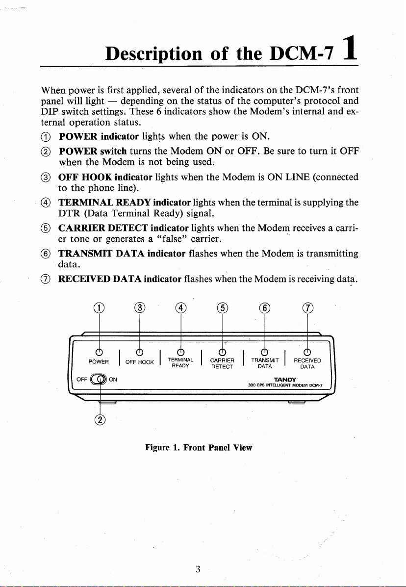
When power
panel will light - depending
DIP switch settings. These 6 indicators show the Modem's internal and
ternal operation status.
G)
POWER
@
POWER
when the Modem
®
OFF
to
@ TERMINAL READY indicator lights when the terminal
DTR
®
CARRIER
er
® TRANSMIT DATA indicator flashes when the Modem
data.
(j) RECEIVED DATA indicator flashes when the Modem
is
first applied, several
indicator lights when the power is ON.
switch turns the Modem
is
not being used.
HOOK indicator lights when the Modem
the
phone line).
(Data Terminal Ready) signal.
DETECT indicator lights when the Modem receives a carri-
tone
or
generates a "false" carrier. ·
CD
POWER I OFF HOOK I
®
on
the status
TERMINAL
READY
of
the indicators
of
ON
or
®
CARRIER
DETECT
on
the DCM-7's front
the computer's protocol and
OFF.
Be
sure.
to
turn
it OFF
is
ON
LINE (connected
is
supplying the
is
transmitting
is
receiving
dat~.
®
I TRANSMIT I RECEIVED
DATA DATA
TANDY'
300
BPS
INTELLIGENT MODEM DCM-7
ex-
Figure 1.
Front
3
Panel View
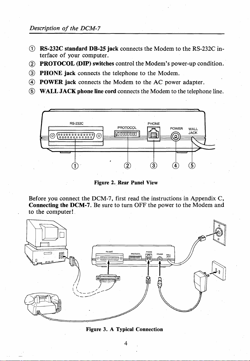
Description
CD
RS-232C standard DB-25
terface
@
PROTOCOL
@
PHONE
@
POWER
® WALL
of
the DCM-7
of
your computer.
(DIP) switches control the Modem's power-up condition.
jack
connects the telephone to the Modem.
jack
connects the Modem to the
JACK
phone line cord connects the Modem to the telephone line.
jack
connects the Modem to the RS-232C in-
AC
power adapter.
PHONE
CD
Figure 2
Before you connect the DCM-7, first read the instructions in Appendix
Connecting the DCM-7.
to
the computer! .
Be
Figure 3. A Typical Connection
..
Rear Panel View
sure to
turn
®
OFF
the power to the Modem
© ®
C,
and
4

Chapter 1
Protocol (DIP) switches
DIP switches control the DCM-7's power-up condition. These switches must
be set before you turn the power ON.
First, you will have to decide whether you want to use the Modem in the
Tandy protocol mode or Hayes protocol
munications software, you will want to
with Hayes communications software, set it to the Hayes protocol mode.
(Both
the
Tandy
with either communications software.)
Tandy protocol
When you select Tandy protocol mode, set
the Modem to set other
Figure 4 for the suggested switch settings in this mode (black portion shows
the switch position).
NO
NO
TRUE
1000
and 1200
DIP
and
switch functions as listed in Table
FUNCTION~
FUNCTION~
CARRIER!
DTR
TRUE
1 1
mode~
3000 personal computers can be used
m=;NO
~AUTO
If
you are using Tandy com-
set it for Tandy protocol.
DIP
Switch 7 to ON. This tells
1.
FUNCTION
ANSWER DISABLE
For
Refer to
I HAYES PROTOCOL
No
1
FUNCTION
1
use
l1~~~~~~11l~.
01
2 3 4 5 G 7 8
N -
FORCED DTR J I
FORCED CARRIER TANDY PROTOCOL
NO FUNCTION..
NO FUNCTION - . .
Figure 4.
DIP
1111
..
. . . ... AUTO ANSWER ENABLE
Switch Settings in Tandy Protocol Mode
5
1~
I L NO FUNCTION
..
NO
FUNCTION
Description
of
the DCM-7
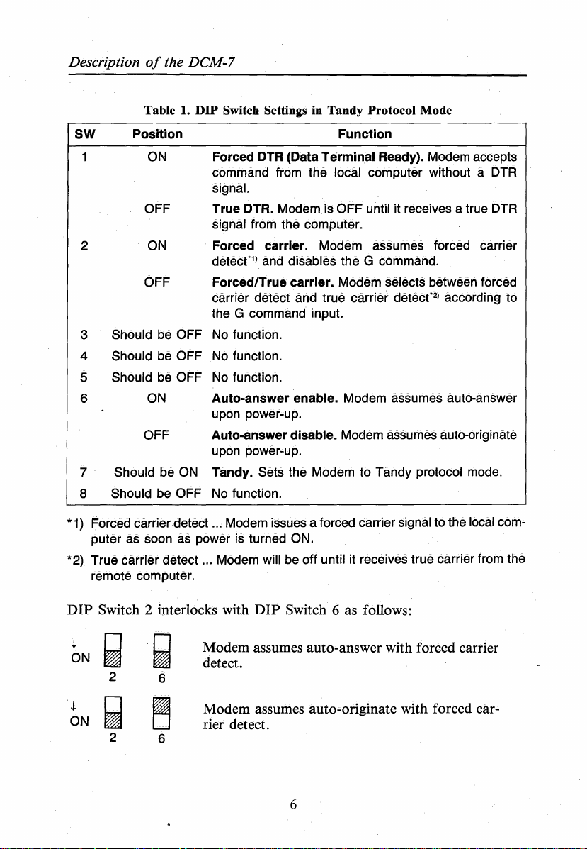
Table 1.
SW
2
3
4
5
6
7 Should be ON Tandy. Sets the Modem to Tandy protocol mode.
8 Should be OFF No function.
Position
ON
OFF
ON
OFF
Should be OFF
Should be OFF
Should be OFF
ON
OFF Auto-answer disable. Modem assumes auto-originate
DIP
Switch Settings in Tandy Protocol Mode
Function
DTR
Forced
command from the local computer without a DTR
signal.
True DTR. Modem is OFF until it receives a true DTR
signal from the computer.
Forced carrier. Modem assumes forced carrier
detecf1> and disables the
Forced/True carrier. Modem selects between forced
carrier detect and true carrier
the G command input.
No function.
No function.
No function.
Auto-answer enable. Modem assumes auto-answer
upon power-up.
upon power-up.
(Data Terminal Ready). Modem accepts
G command.
detecf2> according to
*
1)
Forced carrier detect ... Modem issues a forced carrier signal to the local com-
as soon
puter
*2) True carrier detect ... Modem will be off until it receives true carrier from the
remote
DIP
Switch 2 interlocks with
i
ON
i
ON
as
computer.
power is turned ON.
DIP
Switch 6 as follows:
Modem assumes auto-answer with forced carrier
detect.
Modem assumes auto-originate with forced
rier detect.
car-
6
Chapter I
i
ON
~
2
i
ON
~
2
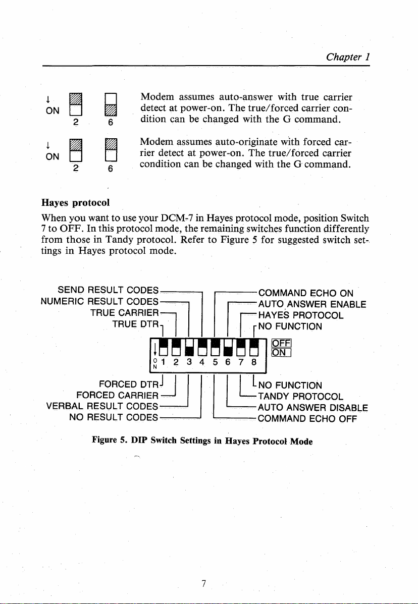
Hayes protocol
When you want to use your DCM-7 in Hayes protocol mode, position
7 to
OFF.
from those in Tandy protocol. Refer
tings
in
SEND
NUMERIC
VERBAL RESULT CODES
NO
~
6
~
€)
In this protocol mode, the remaining switches function differently
Hayes protocol mode.
RESULT CODES
RESUL_ T COD-
TRUE
FORCED
FORCED
RESULT CODES ---_
Modem assumes auto-answer with true carrier
detect at power-on. The true/forced carrier condition can be changed with the G command.
Modem assumes auto-originate wlth forced carrier detect at power-on. The true/forced carrier
condition can be changed with the G command.
to
Figure 5 for suggested switch
~COMMAND
ES
-
CARRIER~
TRUE
DTR
11~~-
~1
ornJ
CARRIER~
11
1 1
w~~w~~
2 3 4 5
I
11 · 111
- - . _ - AUTO ANSWER DISABLE
- - - COMMAND ECHO OFF
JG-
jHAYES
1
€)
7 8
--
AUTO.ANSWER ENABLE
rNo
FUNCTION
1~
LNo
FUNCTION
TANDY PROTOCOL
ECHO
PROTOCOL
Switch
set-.
ON
Figure 5.
DIP
Switch Settings in Hayes Protocol Mode
7
Description
of
the DCM-7
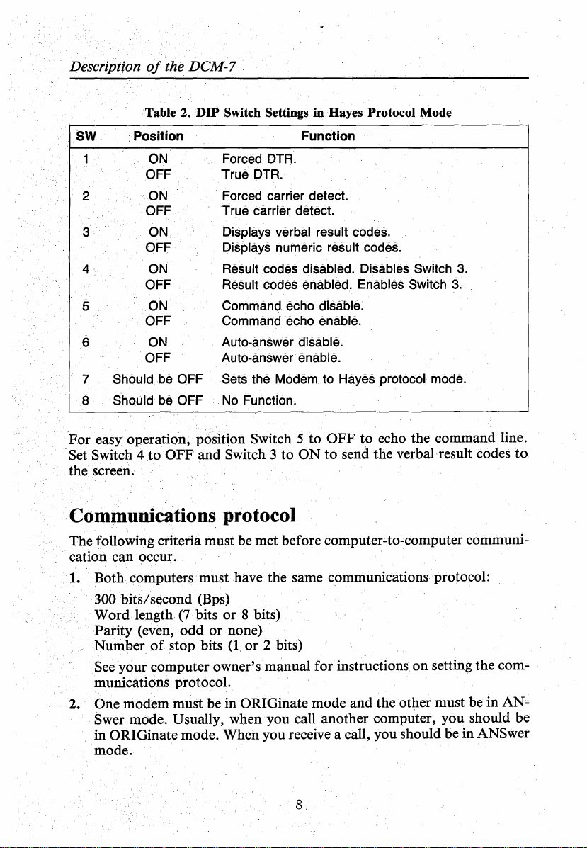
Table 2.
SW
2
3
4
5
6
7 Should
8 Should
For
Set Switch 4
•Position
ON
OFF True
ON
OFF
ON
OFF
ON
OFF
ON
OFF
ON
OFF
.easy operation, position Switch 5 to OFF
to
DIP
be
OFF
be
OFF
OFF
and Switch 3 to
Switch Settings
Forced
Forced carrier detect.
True carrier detect.
Displays verbal result codes.
Displays
Result codes disabled. Disables Switch
Result codes enabled. Enables Switch 3.
Command echo disable.
Command echo enable.
Auto-answer disable.
Auto-answer· enable.
Sets the Modem
No
OTA.
OTA.
Function.
in
Hayes Protocol Mode
Function
numeric result codes.
to Hayes protocol mode.
to
echo the command line.
ON
to
send the verbal result codes
3.
to
the screen.-
Communications protocol
The following criteria must be met before computer'-to-computer communication can ·occur.
1.
Both
computers must have the same communications protocol:
300 bits/second (Bps)
Word length
Parity (even, odd
Number
See your computer owner's manual for instructions
munications protocol.
One modem must be in ORIGinate mode and the other must be in
2.
Swer mode. Usually, when you call another computer, you should be
in ORIGinate mode. When you receive a call, you should be in ANSwer
mode.
of
stop bits
(7
bits
or
or
8 bits)
none)
(1
or
2 bits)
on
setting the com-
AN'"
8.
Chapter 1
The DCM-7 provides automatic and manual operations in both originate and
oi
answer modes. When opened for programming by the wake-up
code sequence, it will automatically synchronize the speed rate, word length,
and
parity
system.
Helpful Tip:
Whe,n
. garbled data, use the self-test mode to help you find the cause
Refer
or in Appendix B, Hayes protocol reference.
If
you plan to use the PCM-7 in Tandy protocol mode only, you may skip
Chapter 3 and Appendix
tocol mode only, you may disregard Chapter 2, and Appendices A and D.
Refer also to the operation mariual which accompanies your
tions software package.
stop-bit numbers (communications protocol)
you use your
to
the section
DCM-:-
7 for the first time
on
self-test in Appendix A, Tandy protocol reference
B.
However,
or
if
you intend to use it in Hayes· pro-
when you seem to be getting
of
attention
your computer·
of
the problem.
communica"'."
9

·
....
Tandy protocol mode operation 2
This chapter will give you an idea
protocol mode. A Videotex Plus communications package for Tandy's Model
16
II, 12,
With this software package you can communicate with a variety
tion services and host computer systems. The examples will help familiarize
you with some
If
you are using an MS-DOS operating system, move directly to the auto
logon session using DeskMate's Telecom in Chapter 3, Hayes protocol mode
operation. XENIX users may want to skip to Appendix D.
For a detailed discussion
refer to Appendix
and 6000 microcomputers
of
the operations the Modem
of
A.
of
what the DCM-7 can do in the Tandy
is
used in the sample sessions following.
of
informa-
is
capable
all the available commands in Tandy protocol,
of
performing.
Manual v. automatic operation
When you want to dial an information service (such as CompuServe or Dow
Jones)
VIDTEX, set the Modem to manual operation mode.
control what the system does by manually dialing and answering the phone.
When you want the DCM-7
for you, set it to automatic operation mode.
the phone number you store in its memory
one calls you. Automatic mode, for instance, lets you dial the information
service number without picking up the phone - just type the number along
with the proper DCM-7 programming commands on the computer keyboard.
or
communicate with another person whose computer
In
- -
to
dial a phone number
In
this mode, the Modem dials
or
answers the phone when some-
or
is
also using
this mode, you can
answer the phone
Originate v. answer mode
To place a call to
set
the DCM-7 to originate mode. In this mode, the call originates from your
computer. When you want to receive a call (answer the phone), set the DCM-7
to answer mode. Note that originate and answer modes can be used either
manually or automatically.
an
information service
or
another person using VIDTEX,
Sample programming sessions
All Modem functions are controlled by ASCII encoded commands that you
from
send
the DCM-7 for programming.
1. Check again that all peripherals are correctly connected and receiving
your computer keyboard. Use the wake-up
power.
11
command*
to open
Tandy protocol mode operation
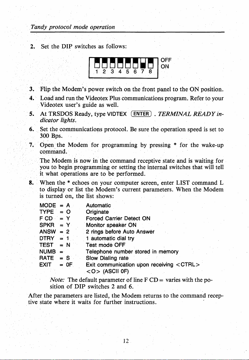
2. Set the
3.
Flip the Modem's power switch
Load.and run the Videotex Plus communications program. Refer to your
4.
DIP
switches as follows:
on
the front panel to the
ON
position.
Videotex user's guide as well.
5.
At
TRSDOS Ready, type VIDTEX
(ENTER)
•
TERMINAL
READY
dicator lights.
6. Set the communications protocol.
300 Bps.
7~
Open
the
Modem for .programming by pressing * for the wake-up
Be
sure the operation speed
command.
The Modem.
you
to
it what operations are
8. When the
to display
is
turned on, . the list shows:
MODE
TYPE
FCD
SPKR
ANSW
DTRY
TEST
NUMB
RATE
EXIT
Note: The default parameter
sition
is
now in the command receptive state and
is
waiting for
begin programming or setting the internal switches that will tell
to
be performed.
* echoes
or
=A
=0
= y
=Y
2
1
N
= s
=
OF
of
on
your computer screen, enter LIST command L
list the Modem's current parameters. When the Modem
Automatic
Originate
Forced Carrier Detect
Monitor speaker
2 rings before Auto Answer
automatic dial try
1
Test
modeOFF
Telephone number stored in memory
Slow Dialing rate
Exit communication upon receiving < CTRL >
< 0 > (ASCII
DIP
switches 2 and 6.
OF)
ON
of
ON
line F
CD=
varies with the
After the parameters are listed, the Modem returns to the command
tive state where
it
waits for further instructions. "
is.
set to
po'-
recep..;.
in-
12
Chapter 2
CompuServe logon
CompuServe Information Service
is
widely known for its numerous on-line
services for both business and home computer owners. Dedicated telephone
numbers in major cities provide you access to CompuServe.
Use your infor-
mation service user's guide to find out how to contact and use the service.
Since the DCM-7
your command - all you have to do to begin the logon
is
already in the command receptive state - waiting for
is
prepare the Modem
to dial the information service access number.
1.
Press
@to
place the Modem in the dialer programming mode.
example,
if
you enter (111)555-1234 as your local access number for
touch-tone dialing, the sequence appears as:
DT(111)555-1234
If
you're using a rotary (pulse) type telephone, type R instead
2. When the phone number
prQtocol reference),
lin~s
and to begin dialing the number. OFF
The
screen shows:
DIALING ... T(111)555-1234
CONNECT
Dialing
...
- -
and connect are the Result codes (discussed later in this sec-
tion) which keep you informed
If
you received a? instead
is
properly formatted (see D command, Tandy
press®
to force the Modem to seize
HOOK
of
the status
of
the message shown, you probably entered
or
progress
the
indicator lights.
of
of
telephone
a phone call.
a key that the Modem did not recognize.
3.
Press ( CTRL) © and type the User ID number that you received with
the
software package when the screen prompts:
User ID:
4.
Next, type the password that you received with the software package
when.
the display prompts: -
Password:
Your password
At this point, your logon to CompuServe
using the
s~rvice.
ply substitute the appropriate dialog as provided in the information
is
not printed
on
the screen to retain its secrecy.
is
complete and you may begin
To use other information services and host systems, sim-
s~rvice
_ user's guide.
For
T.
13
Tandy protocol mode operation
Manual mode operations
When operating in manual mode, you control the system by manually dial-
is
ing and answering the telephone. Manual mode (answer or originate)
when you want to talk by telephone to a friend at a remote location, and
later exchange computer data without redialing.
Example 1. Manual answer mode
The phone rings
a while to your friend, you decide to exchange information by computer
(telecommunications) without breaking voice call:
1. Your friend selects to be the originating station, while you are the answering station.
M
A Select answer mode.
2. Give your friend time to set up the originating modem.
Press
3.
4. The answer station always issues the X command first. After hearing
5. Hang up
Be
sure to keep 'quiet when the handset
cause errors in the
Be
careful when you hang up the telephone since slamming
phone back
disrupt carrier long enough to start a
To return to voice communications after transmitting data:
1. Carefully pick up the handset (both modem stations).
2. Type
®.
you hear through the built-in speaker
while the Modem
the answer modem's carrier tone, the originate station sends the X com-
mand to complete the connection. The Modem goes on line, and you'll
see the
at
you might signal your friend by typing:
THAT'S ALL! I
and
you answer by picking up the receiver. After talking
Set up your Modem by entering:
Wake up!
Select manual mode.
The Modem transmits carrier tone. The carrier
or
when you pick up the receiver
is
in communication with another modem.
CONNECT result code
both
handsets.
data
being passed by the modems.
on
the hook while the modems are controlling the lines could
the keyboard that you will be aborting carrier. For example,
AM
ABORTING CARRIER.
on
the screen.
is
OFF HOOK. Noise picked up could
or
loss;..of-carrier disconnect sequence.
useful
is
the sound
dropping the
14
Chapter 2
3. After making sure your handsetis OFF HOOK, enter the abort character (
e"'fRL) @ to force the Modem
not
have the CTRL key, refer to your computer manual to find out the
of
hex value
key
redefinition
After 3 seconds
result code,
Modem
and
is
in OFF-LINE mode. Press ~ to return
OF,
or change the
@.
Refer to Appendix A, @ command. ·
of
inactivity, your Modem logs out with the DISCONNECT
your friend's modem (if automatic) shuts down, too. The
OFF
LINE.
abort
character using abort character
If
your computer does
to
the command recep-
tive mode.
Example
l.
2:
Manual originate mode
Set the Modem for manual originate mode.
@ for originate. Then, press (!) to check the current parameter settings.
Press~
for manual and
The first two parameters should show:
MODE=
TYPE = 0
M
2. Now pick up the telephone and dial the information service phone number. When the information service answers the phone, you will hear a
high-pitched tone.
3.
Press
®.The
tects the carrier tone, it issues low-pitched tone. Then it goes
and
sends the CONNECT result code to the screen. ·
4.
Gently
hang~
OFF-HOOK indicator lights. As soon as the Modem de-
ON LINE
the phone. You can then begin following the instruc-
tions detailed in your Videotex and information service user's guides.
Automatic mode operations
The DCM-7 can be programmed to make a call
automatically.
In
automatic mode operation, you can call
service without picking up the phone - just type in the phone number
your computer keyboard. You can also tell the Modem to auto-answer your
telephone.
Example 3: Automatic answer mode
1.
To
set the Modem for automatic mode, first type * to enter command
mode, then type
shows
MODE=
firm that the mode
L to display the current parameter· settings.
M, then press ~ for automatic mode. Type L to con-
is
now A for automatic.
or
answer your telephone
an
information
If
on
screen
15
Tandy protocol mode operation
2. Type A to set the Modem
does not show
3. Press ®
the
value
to
force the Modem out
auto-answer mode. The Modem will then wait for the telephone
and
sends:
WAITING
FOR
RING
to
the answer mode
A.
of
command receptive state
if
the
TYPE
parameter·
and
into
to
ring
4. When the phone rings, the Modem begins counting the rings and sends
the RING result code to the display for each ring. After 2 rings, it answers
by seizing the telephone line and asserts carrier. The calling modem replies
with its carrier. Both modems are now
ON
LINE
and
telecommunica-
tions can begin.
is
set
to 2 at
The ring number
power-on. This means your Modem will seize
the phone line after 2 rings. When you want to change this number, press
OJ
for the ring change command when the Modem is in command recep-
tive mode. The display prompts:
ANSWER
When you do
by pressing (ENTER) , which is the CR (Carriage Return) key.
the ring number, type
the ENTER key is accepted.
"echo" the typed key (if displayable)
If
the key you press is a valid entry, the Modem sends the next prompt:
RETRY
For
the time being, press (ENTER)
If
either modem breaks
the abort character,
then the
answer mode
mode,
You can
detects the
ON
1-9
not
FOR
1-9
WAITING
and
it
will continue
turn
OFF
*, it will change
RINGS OR
need
to
in
TIMES OR CR
the
the
FOR
monitors
to
CR
FOR
NO
CHANGE =
change the number
the new number. Note
If
you press any other key, the DCM-7 will
and
FOR
to
connection after a successful
of
rings, answer this
that
only a number key
ask the question again.
NO CHANGE =
skip.
data
prompt
To
change
exchange with
DCM-7 will send the DISCONNECT result code,
RING
result code. This means it returns to auto-
the
line. As long as the Modem
monitor the telephone line for
is
in auto-answer
an
incoming call.
this call-waiting mode by pressing eJ. When the Modem
to
auto-originate mode and return
to
the command
or
receptive state.
Example 4: Automatic originate mode
in
Step 1
of
1. Follow the procedure
2. Type
0 to set the Modem
not show the value
to
0.
Example 3, Automatic answer mode.
originate mode
16
if
the
TYPE
parameter does

Chapter 2
3. Enter the telephone number you want to dial using the D command
Appendix A, Dialer programming mode). You can also specify the dialing method (either pulse
which may be necessary
ple, in the phone number below:
DT9P1234567
T indicates tone, 9
pause and the digits
on
storing a telephone number, refer to Appendix A.
Press
00
4.
gin dialing the number.
5. After detecting the carrier tone
line
If
the Modem does not detect the carrier tone
30
seconds after dialing (due to busy
off
line after sending the NO CARRIER and DISCONNECT result code. To
dial the number again, press
number stored in dialers memory.
number, the Modem displays the
You can also program the Modem to automatically redial (RETRY) the number
in
advance.
respond to the first prompt, a second prompt appears:
RETRY FOR 1-9 TIMES OR CR FOR NO CHANGE =
Again, a valid entry
tries.
If
to force the Modem out
is
connected, the Modem
Il1
this case, press
is
no change is required, just press ( ENTER) •
or
touch".tone), the dialing speed and any pause
to
access
an
outside line in a PBX. For exam-
is
the access code
1234567 are to be dialed.
~·
a number or ( ENTER ) • Input the desired number
to
the outside line, P
For
of
command receptive state and to be-
of
the answer modem, after the telephone
is
ON
LINE.
of
the answer modemwithin
or
no answer condition, etc.), it goes
00
. The Modem automatically dials the
If
you press ® without having stored a
NO NUMBER result code.
CD
for the dial retry command. After you
is
the 2-second
more information
(See
of
-·---------·-----------n
Analog self-test mode
Type
Q,
then type L to confirm
changed to
CONNECT and you are in the self-test mode. Type any characters
keyboard.
RECEIVED DAT A indicators blink simultaneously and the characters you
typed will appear
Check all cables and connections and run the test again. To abort self-test
mode, press
Y.
Type X to
If
the DCM-7 is working properly, the TRANSMIT DATA and
on
the display.
. ( CTRL ) @ for the abort character.
that
the value
execute the test command. The Modem displays
If
not, there are problems with the circuit.
of
the TEST parameter
is
on
now
the

Tandy protocol mode operation
Always auto-answer mode operation
The Modem assumes always automatic answer mode operation when the DIP
Switch
When you type
to
connecting,
returns
This setting is useful when you use the Modem mainly in the answer mode.
6
is
set to
on
at power up, and begins monitoring the telephone line.
* , the Modem enters command receptive mode and changes
automatic originate mode as
or
after receiving the C (clear memory) command, the Modem
to
automatic answer mode.
i:ri
normal automatic answer mode. After dis-
On-line abort conditions
After establishing communications with a remote modem, the DCM-7
monitor mode. In this mode, the parameters are constantly scanned.
one
of
these parameters fails, the DCM- 7 will break communications and
go
OFF
LINE immediately. The parameters monitored include loss
er, the
Loss
The carrier monitored
false carrier generated by the DCM-7. In all modes, except
is removed for longer
and drop the phone line.
loss
In
completed (a
DCM-7
to
keys, press
Manual abort entry
When you send a CTRL 0
with the
will exit monitor mode.
DTR (Data Terminal Ready)
the DCM-7 will terminate communications, just as
abort
character
of
carrier
of
carrier is ignored.
automatic originate mode, when the Modem is waiting for a call
30'-second delay time between dialing
is
looking for a valid carrier signal), you can command the DCM-7
abort the call by inputting any keys including
~to
@ key and do not send any other character for 2 seconds, the DCM-7
and
space disconnect.
is
the one
than
0.3 seconds, the Modem will exit monitor mode
If
the carrier interruption
set the Modem
(OF
HEX)
is
also scanned in this mode.
that
is
sent over the telephone line, not the
TEST,
is
less
than
and
disconnect where the
*.
If
you aborted with other
to
command receptive mode.
or
another character you programmed
If
the DTR
if
the carrier had failed.
of
if
0.3 seconds,
is
is
in
If
any
carri-
carrier
to
be
OFF,
18

Chapter 2
Space disconnect
Your DCM-7 will drop the phone line any time it receives a continuous
RS-232C SPACE (ASCII BREAK or null with no start and stop bits) for
3 seconds from the
is
This
called space disconnect and
r~mote
modem or for 1.5 seconds from your computer.
is
in accordance with Bell
1031
standards
for short and long space disconnect.
To regain control over the Modem after disconnection, input wake-up code
*.
The Modem returns to the command receptive state with the same
parameter settings as before. When you want to change the parameters to
the default settings, press
© .
Note: The clear memory command C sets the Modem to off-line
~
mode. Press
again to enter command receptive mode.
Result codes
The DCM-7 sends the result codes to report its status or telephone line condition.
Table 3. Result Codes
Result Code
?
NO
NUMBER
DIALING ...
CONNECT
NO CARRIER
. DISCONNECT
WAITING
RING
FORCED
IS
ON
FOR
CD
RING
SWITCH
The command input is invalid.
Th~re's
Modem
Detected
Does not
Goes
Mod~m
ring
D~tects
phone line. ·
Since
accept G command (Refer to
Protocol (DIP) switch.)
no number to be
is
dialing the number that follows.
carri~r
receiv~
on
hook after the connection .
is
monitoring the
signa,I.
an
incoming ring
DIP
Switch 2
Meaning
dia,l~d
and goes
carrier or lost it.
on
tel~phone
~
s~gna,I
i~
ON, Modem
lin~.
Chapt~r
in
the memory.
line for a
on
the tele-
do~s
1
not
19


Hayes protocol mode operation 3
In Hayes protocol mode, commands instruct the DCM-7's operation and
register values determine how the commands will be executed. The command
is
structure
mand, which makes the DCM-7 Hayes-software compatible.
Command codes
All command lines in Hayes protocol mode begin with the
code) string and end with a carriage return (
in uppercase letters,
upper- or lowercase letters.
will automatically set the operation speed (in Bps)
You can store a sequence
provided the command line does not exceed the 40-character buffer capacity.
These commands, however, must be entered in logical order in order to
be
executed.
will not
Example 1. Sample command line
AT
Now, to review the commands, one by one:
AT
V1
S6=3
DP9,
T
R
(ENTER ) End of command line. Execute all commands.
The attention code AT, control characters and spaces do not take up space
in the command
make it easier to read does take up space. Input the attention code AT, reset
command Z, or
mand buffer.
patterned from the industry standard AT-string-interface com-
ENTER
) •
AT
must be entered
but
the commands following can be entered in either
When the
of
commands in the command buffer memory,
If
the command line
execute
V1
the commands and instead sends an error result code (Table
S6
= 3 DP9, T(111)123-4567R (ENTER)
B~ginning
receptive mode.
Displa,y
in
this chapter.)
Wait 3 seconds for the dial tone.
Dial 9 by
of
regist~r
Touch-tone
Cha,nge
buff
turn
of command line.
the verbal result code. (Refer to Result codes later
pul~e
SS).
dia,I
to
answ~r
er. The punctuation used in the telephone number to
OFF the power supply
AT
command
exceeds
dia,ling, then pause 2 seconds (defa,ult
(Refer to
the
the buffer-character limit, the Modem
Plac~
th~
section
t~lephone
mode
a,nd
wait for carder.
of
is
received, the DCM-7
and
parity.
the Modem
on
Registers.)
number that
follow~.
the Modem to clear the com-
AT
(attention
in
command
8).
valu~
21

Hayes protocol mode operation
The basic commands needed for programming the Modem in Hayes pro-
5.
tocol mode are provided in Table
commands. For a detailed explanation
B,
Hayes protocol reference.
Table 6 lists the dialing and answering
of
each command, ref er to Appendix
Commands with parameters
Some
of
the commands have parameters. The parameter value, usually 0,
1 or 2, follows the command. When the command parameter
of
the Modem assumes a value
not echo when parameter
issued. E used alone
Code Parameter
Q
v
0 Result codes ON. Defined by DIP Switch
1
0 Numeric result codes. Defined by DIP Switch
1
is
the same as
Table 4. Commands with Parameters
Result codes
Verbal result codes.
0. For example, the echo command E does
0
is
assumed.
It
does echo when parameter 1
EO.
Function
OFF.
is
Default
not used,
4.
3.
E 0 Commands are not
echoed.
1
F 0 Half duplex.
1
M 0 Monitor speaker always
2
Echo commands.
Full duplex.
OFF.
Monitor speaker
until carrier-detect.
Monitor speaker always
ON.
ON
c 0 Transmitter OFF.
1 Transmitter ON.
H 0
ON
HOOK (phone line
disconnected when not
use).
OFF-HOOK (phone line
connected regardless of
its condition).
is
in
is
Defined by
F1
M1
C1
HO
DIP Switch
5.
is
'JO
22

Table 5. Basic Command Codes
Code Description
AT Attention Code
CR Carriage Return
BS
+ + + Escape
0 On-line
z
Backspace
Codf3
Reset
Table 6. Dialing and Answering Command Codes
Chapter 3
Function
Wakes up the Modem to command receptive
st?te. Starts the command line.
Closes
mands. Register
return character.
Edits the command line by deleting characters one
backspace character.
Returns the Modem to command mode from
on-line mode. ·Register
code character.
guard time.
Returns the Modem to
conim?nd mode.
Resets the Modem to default condition.
the .command line ?nd executes com-
S3
defines the carriage
·
by
one. Register
s·12
S5
defines the
S2
defines the escape
defines the escape code
on-line mode from
Code Description
Sets the Modem to originate ? telephonf3 call.
D command par?meters include: 0-9, (
space, *, and # .
P Pulse
T Touch-tone
R Reverse
(comm?) Follows
; (semicolon)
A/
A
Pause
Rf3peat
Answf3r
Dia.I
Dial Sets the Modem to touch-tone dialing
Modf3
Comm?nd Repeat$ the comm?nd line. AT and ENTER
Mode lmmedi?tely
Sets the
Automatically changes the Modem to answer
mode
C?uSe$
set by Register
Returns the
dialin9.
are not
without
Function
Modf3m
?fter ? call
the Modem to pause while di?ling.
the
nf3cess?ry
waitin9 for a ringin9 sign?I.
23
to pulse dialing mode.
i$.
originated.
?Ccess
code. Length of pause
SB.
Modf3m
Sf3ts
to comm?nd mode ?fter
for this command.
the Modem to
·
answf3r
),
modf3.
is
mode

Hayes protocol mode operation
Registers
Registers are used to store the parameters which control communications.
Each register has variables
plies information
on
registers:
Register Range Unit Function Default
so
S1
S2
S3
S4
S5
S6
S7 1-255
SB
S9
S10 1-255
S11
S12 20-255
S13-S15
S16
0-255 Ring Defines the rings in answer mode.
0-255 Ring Counts the rings.
0-127 ASCII code Defines the escape code character. 43
0-127
0-127 ASCII code Defines the LF code character.
0-32,127
2-255 Seconds Defines the dial tone wait time. 2
0-255
1-255
50-255 Millisec. Defines touch-tone dialing speed. 70
0
that
determine how the DCM-7 operates or sup-
the Modem's current condition. The DCM-7 has
Table 7. Registers
ASCII code
ASCII code Defines the BS code character. 8
Seconds
Seconds Defines pause
1110
sec. Defines carrier detect response 6
1110
sec. Defines carrier loss time to hang 7
1150
sec. Defines escape code guard time.
Defines the
Defines the carrier wait time.
(actual maximum value is 54, but
a value up to 225 can be input).
time.
up.
Not used.
Self-test mode OFF.
Self-test mode ON.
CR
code character.
duration for comma
14
0*3)
0
13
10
30
2
so
0
*3) When DIP SW 6 is OFF, the Modem will power-up in auto answer with
Register
register
ters; registers
SO
defines the number
Sl
counts the rings; registers
of
ringing signals before a call
S2-S5
define the function key charac-
S5-S12 control the function time and register S16
is
answered;
is
self-test.
Note: The ASCII code values are expressed in decimal.
24
so=
1.
for the

Chapter 3
Command
You can read the current value
the registers
mand
Sx? Check the register value
To
check the value
are displayed
value
AT S2? (ENTER)
On
the screen, you will see -
043
OK
You can also check the values
To
check the values
AT S3? S4? (ENTER)
syntax
to
your particular environment by using the Sx?
syntax.
of
on
the screen
of
register 82, type:
of
a register
or
assign a new value
a register, use the Sx? syntax. The value
in
of
register 83
qecimal numbers.
of
plural registers in the same command line.
and
register 84, type:
For
example,
to
or
Sx=
n com-
of
the registers
to
check the
match
The screen might show:
013
010
OK
Sx=n
Use the
the value 3
AT
Change the register value
Sx=
SO=
n syntax
to
3 ( l;N"fER)
register
to
SO,
assign
or
change the value
type: ·
of
a register.
To
assign
After changing the value, the Modem signals OK. Another syntax for chang-
regis~er
ing a
AT
SO
AT?
AT=
3 (
For
more information
value is:
(ENTER)
(ENTER)
EN"fER
Set the pointer to register
Read the value of
)
Assign
on
the registers, refer
th~
new value 3 to
SO.
to
SO.
SO.
·
Appendix B, Hayl'S protocol
reference.
25

Hayes protocol mode operation
Result codes
Result codes are displayed in either numeric
mand line
Command
Ql
is
you can see the codes
or
verbal (Vl) codes.
The default values
when
unless
Numeric
is
executed.
Q determines whether the result codes will be displayed. When
selected, the result codes will not be displayed. When
on
the screen. Command V selects either numeric
of
these controls are fixed by
DIP
Switch 4
QO
is
entered from the keyboard. (Refer to Chapter
0 OK Executed the command line without errors.
CONNECT
2
RING Detected
NO CARRIER Carrier was lost
3
4
ERROR Error
is
set to ON, the result codes do
Table 8. Result Codes
Verbal Meaning
Detected carrier.
an
in
the command line, command
(not recognized by the Modem), or the command
line exceeds command buffer size.
or
verbal code after the
QO
is
selected,
DIP
switches.
not
incoming phone line ring signal.
or never heard.
appear
1,
DIP
For
example,
on
the screen
switches).
is
invalid
com"'
(VO)
Logons in MS-DOS operating systems
With DeskMate's Telecom applications program and your Tandy Personal
Computer, you can easily program your DCM-7 to log
information service
-Follow the instructions in your DeskMate Tutorial
for setting the parameters and using the functions available. Depending
the computer you are using, the procedures may differ slightly from those
shown. A Tandy
1. Power up the computer and load your communications software. Set
the
DIP
switches
or
another terminal either manually
1000
PC
is
used for the examples following.
on
the DCM-7 as follows:
on
to a host computer,
or
automatically.
and
Reference manual
on
I
~~.
~~.~~~~I
1 2 3 4 5 6 7 8
26
g~

·chapter 3
2.
At
the Main Menu, select Telecom and change the TELECOM-STATUS
screen io show:
Autodi?I
BAUD
Data Word Length
P?rity .
Number of Stop Bits
XON/XOFF Flow Control
ASCII
Line Feed Filter
Echo (Half Duplex)
R~dial
Mod~m
Rate
Character Filter
( # of Retries)
Yes
300
8 BITS
NONE
1 BIT
ON
OFF
OFF
OFF
0
3. Select "Yes" for the Autodial Modem status setting and press
When the DEFINE MODEM FOR COMPUTER DIALING screen appears, change the dialing sequence to show:
PAUSE: 2 Pause for 2
SEND: ATDT W?ke
touch-tone
NUMBER Send
terminal mode.
SEND: "M
WAITC Wait for carrier
Note:
If
your telephone system requires pulse, rather than touch- .
S~nd
cute the commands:
tinuing.
tone dialing, change ATDT to
4.
Press
(f=12)
twice to return to the TELECOM-STATUS screen after sav-
ATDP
second~.
up
and originate ? call using
di~ling.
number which will
~M
to force the DCM-7 to exe-
d~tect
b~
before con-
in the first SEND line.
input
ing the dialing sequence.
@.
·
at
Manual logon
1. Enter terminal mode from the
2.
At
the TERMINAL MODE screen, press
number
of
the information service, then press (ENTER ) •
TELECOM-STATUS
@ID
and type in the telephone
scre~n
3. After the connection has been made successfully, proceed with
procedures step by step.
27
(
(EID
).
thelogon

Hayes protocol mode operation
Automatic logon •
1.
At
the TELECOM-STATUS screen, press
and enter your log file name, then press (
the
STATUS line. After selecting the parameters, press (F12) to return
to
the original screen
and
complete the rest
(§)to
ENTER ) • Press
create
of
file. When completed,
an
autolog file
(ED
the screen for your autolog file might show:
STATUS:Y,30,8,
CALL: 123-4567 (Use your local TELENET number.)
PAUSE:S
SEND:
RECV: TERMINAL=
SEND: D1"M
RECV: @
SEND: C 60942"M
RECV:
SEND: DJNS"M
AM''M
????
2. Press ( F12) (ENTER )
N,
1,0N,OFF,OFF,OFF,O
to
save this autolog file
and
return
TELECOM-STATUS screen.
3. Input
@ filename (ENTER ) to execute your autolog file. When the
logon sequence is entered correctly, the DCM-7 will dial your local access number' connect to the service, then automatically execute the rest
·or
the autolog file.
to create
to
the
28

Appendices
I

·
....

Tandy
protocol ref ere nee A
When you use your DCM-7 in automatic mode, you
or
numbers
pick up your telephone receiver
does all that for you. As long as you're going
to
to
don't
have
answer a call
be
at
your computer through-
-your
to
dial any
DCM-7
out communications, you can control the DCM-7 and your telephone through
your computer keyboard.
You can also send
at
your computer keyboard.
gram
and
use the commands
(automatic originate)
By programming your DCM-7
computer after
take advantage
The DCM-7
9. These commands can be entered either
Command
@
A,
a
C, c
D, d
P, p
R,
r
T,
t
E, e
F,
f
G, g
I,
i
L,
I
M,m
0,
0
P, p
Q,
q
S, s
X,
x
or
receive
12
midnight, for example, you'll save time
of
lower telephone rates.
is
completely programmable using the commands shown in Table
Table 9. Programming Commands
Wake up command
Redefine abort character
Answer mode operation
Clear memory
Enter dialer programming mode
Pause subcommand
Pulse (Rotary) dial subcommand
Touch-tone dial subcommand
Command echo disable/enable toggle
Fast dialing speed
Forced carrier detect toggle
Ring/Retry change command
List parameter settings
Manual/automatic toggle
Originate mode operation
Monitor speaker ON/OFF toggle
Self-test command
Slow dialing speed
Execute command(s)
data
from another computer while
Just
write a BASIC
to
program your DCM-7
or
answer (automatic answer) the phone unattended.
to
download daily information
Description
1.n
or
machine-language pro- .
upper-
or
lowercase letters.
CTRL 0 (HEX
Originate mode
Pulse (Rotary)
Echo
Slow dialing
DIP Switch 2/6
Ring 2/no
Automatic
Speaker ON
you
to
dial a number
to
another
and
be
Default
enable
retry
are not
able to
OF)
31

Tandy protocol reference
Command description
This section details how to program the DCM-7 using the commands listed
in Table 9.
·
* Wake-up command
This command
off-line state and into the command receptive state.
will need to precede any command with the
The wake-up command
(2)
abort the waiting-for-carrier state (after dialing
terrupt the waiting-for-ring state when the DCM-7
When the
to ring), it terminates the answer mode.
When used while the DCM-7
Modem will stop dialing, displays
mand receptive mode.
The
* command can be used
be echoed to the computer,
is
used
to
wake up the DCM-7 -
is
also used to (1) abort (turn off) the dialing process;
*
is
used while the DCM-7
that
is, switch from the
At
initial power-up, you ,
*
..
is
complete); and
is
in auto-answer mode.
is
waiting for a
is
dialing in automatic originate mode, the
DISCONNECT and return
at
any time while in command mode.
but
no action will occur.
tdephone
call (phone
to
(3)
in-
the com-
It
will
@ Redefine
The abort character allows the Modem to be disconnected under software
control. With this command, you can change the. default abort character
CTRL
To program this symbol, press
be stored
CTRL
CTRL R would be listed as EXIT
character, it
the echo switch
The DCM-7 will watch for transmitter activity for 3 seconds after the abort
code
will abort any
within
0 into any ASCII character you like.
as
the abort character. For example, to change the abort code from
0 to CTRL R after doing a List command, you would type:
@ CTRL R
will
not be echoed on the screen. Only @
is
is
sent.
If
there
ON-LINE activity in progress.
that
3-second period, the DCM-7 will ignore the abort command.
abort
character
@ . The next key the Modem receives will
==
12
(in HEX). When you enter the ASCII
will
be echoed, provided
not disabled.
is
no activity during that 3:-second period, the computer ,
If
there
is
keyboard activity
32

Appendix A
A, a Answer mode operation
The Modem
up. The A command
em to an answer modem.
a call from a modem which
is
defaulted to operate in originate mode when first powered
is
used
to
change the DCM"7 from
Use the answer mode when you want
is
operating in originate mode. The M command
an
originate mod-
to
receive
(manual/automatic toggle) determines whether the Modem will wait for the
telephone to ring (auto answer) or seize the telephone line as soon as you
exit the command receptive state with the X (manual answer).
You can enter this command repeatedly. There
is
the DCM-7
plications software
already in answer mode. You rriay want to
to
be sure the DCM-7
is
no harm in entering A when
put
A in your ap-
is
in answer mode before running
the program.
C, c Clear memory
The C command clears the DCM-7's memory and resets all the parameters
to the default values. There
execute command
(X), because the memory
pressed. After this command
Use the wake-up command
You can use the C command when you have changed several
you do not want to go back and change each one.
having to cycle the power switch
is
no need to follow the C command with the
is
cleared immediately when ©
is
issued, the DCM-7 returns
(*)to
enter the command receptive mode.
to
off-line mode.
parameters and
It
also saves you from
OFF and ON.
is
D,
d
Use this command
enter the D command, the dialer memory
Enter dialer programming mode
to
enter the dialing parameter setting mode. When you
is
cleared and the DCM-7 waits
for the following subcommand entries:
0-9,
*,
# (Telephone number and code)
These must be valid digits that can be dialed
on
the phone. The * and #
are used only in the touch-tone dialing mode for special service.
P,
p Dial pause subcommand
Wait here for 2 seconds before dialing the rest
to
to enter this command
behind a
R,
PBX.
r
Pulse (rotary) dial subcommand
access an outside line when your phone is located
of
the digits. You may need
Sets the DCM-7 to pulse dialing mode.
33

Tandy protocol reference
T,
t Touch-tone dial subcommand
Sets the DCM-7 to touch-tone mode.
(,),
-,
<space>
Enter these symbols
are
i~nored
by the dialer routine, but are accepted and stored in the dialer
to
make the phone number easy
memory.
to
read. These entries
BS
The
BS
code
typing a number and make an error, press
typed.
If
BACKSPACE
is
simply
an
code
editing feature for the D command.
@ID
to delete the last character
If
you are
you press @[) immediately after .selecting the D command, a ?
will appear to indicate an error condition.
of
up
to
40
A total
and
stored
until you
dialed by the DCM-7. The stored number will be kept in memory
turn
digits and symbols that follow the D command can be
off
or reprogram the DCM-7 by entering
Dor
C. Use the list
command to confirm the number.
The pulse dialing mode
dialing mode
of
the previous call
is
the default condition and the Modem applies the
if
R nor T does not precede the telephone
number.
DCM.:7 allows you
The
to
mix signaling types in a telephone number. For
example, the sequence DR234333PPT-(lll)-123-4567 says to pulse dial the
number 234333, pause for 4 seconds, then tone dial the
number 1111234567.
The dashes, parentheses and space are ignored by the DCM-7 during dialing.
If
you have problems when using touch-tone
your telephone line may not be suitable for these modes.
and/or
E, e Echo disable/ enable toggle
This code
the slow dialing rate. Refer to dialing speed commands F and
is
used to disable or enable the "echo" function. When enabled,
and/or
the fast dialing rate,
Use rotary dialing
S.
the echo supplies feedback to your computer's display. When disabled, data
you send to the DCM-7 will not be echoed to the computer display, including the parameter settings. The display will not show anything, even
type
L.
If
the echo feature
is
tually it
working normally.
The default (power-up) setting
is
disabled, the DCM-7 will appear -dead, but ac-
of
echo function
is
the echo enable.
if
you
34

Appendix
A
F, f
When you want to tone
Fast dialing speed
or
pulse dial using faster signaling rates, you can
use this command. The F command forces the Modem to dial while in the
automatic originate mode
pulses/second (pps)
then show RA TE
for
= F.
Note: The fast dialing speed command
dialing. Fast pulse dialing
at
10
digits-per-second for touch-tone
pulse dialing. The RATE = S line
is
mainly used in touch-tone
is
seldom used. When you experience
on
the listing will
or
20
difficulty in fast pulse dialing, set the rate to slow.
G,
g Forced carrier detect toggle
is
This command
(FCD). When the
used to
FCD
nal to the computer
lights. When the
FCD
the computer when it detects a true carrier signal
turn
on
and
off
the forced carrier detect signal
is
ON, the DCM-7 issues a forced carrier detect sig-
upon
power-up, and the CARRIER DETECT indicator
is
OFF, the DCM-7 issues a carrier detect signal to
on
the telephone line and
lights up the CARRIER DETECT indicator.
The default condition
G command
switch
FORCED
is
disabled when
is
ON, the Modem informs you by showing:
CD
SWITCH IS ON
You can check the status
this command
DIP
of
the FCD at the FCD = parameter listing by us-
is
SW 2
set by
is
ON.
DIP
switches 2
If
you input G when the
and
6.
The
of
ing the L command.
I, i Ring/retry change command
to
This command allows you
change the answer
The I command displays the intermediate menu. When you press
on
n rings
or
retry n times.
Q) , the
DCM-7 prompts:
ANSWER
ON
1-9
RINGS OR
CR
FOR
NO CHANGE =
The cursor (if used) will be positioned after the = sign and await your input.
If
you press (ENTER ) instead
that you want to keep the already programmed number
ber between 1 and 9
are not accepted.
or
If
you reply
the ( ENTER ) key
will echo the key (display the key you just entered,
of
typing a number, the DCM-7 assumes
of
rings. Only a
is
a valid entry. All other entries
to
the prompt with an invalid entry, the DCM"7
if
displayable)
and
nuni""
ask
the question again.
35

Tand~
protocol
ref
ere nee
When you correctly respond to the first prompt, the display shows the next
prompt:
RETRY FOR 1-9 TIMES OR CR FOR NO CHANGE =
Here again, only a numbe; in the range 1 to 9
The prompt
is
asking you how many times the DCM-7 should try a telephone
number before exiting the auto-dialer routine. Enter a value
if
you want· it to redial the number.
When your response
is
acceptable, the DCM-7 will return to the command
or
the (.ENTER) key
of 2 or
is
valid.
greater
receptive mode, ready to accept the next command.
The DCM-7 will look for a valid carrier tone from the remote modem.
carrier
is
not detected within
30
seconds, your DCM-7 gives up and prepares
If
for the next try.
L,
1 List command
The list command
The screen
shows:
MODE=
TYPE
F CD = Y
SPKR = Y
ANSW = 2
DTRY = 1
TEST = N
NUMB=
RATE = s s (Slow),
EXIT
= 0
=
A
OF
is
used to review the current state
Table 10. List Settings and Related Commands
Parameter
A (Automatic
o
(Ori€Jinate),
Y (On-line), N (Off-line)
Y (Monitor speaker on), N (Monitor speaker off)
1-9
1-9
Y
(Self-test on), N (Self-test off)
0-9, T (Touch-tone), R (Pulse), ·p (Pause),
space,
Hex code for abort character
*,
F.
),
A (Answer)
#
(Fast)
M (Manual)
of
the DCM-7.
-,
(,),
Related
Commands
M
O,A
G
p
I
I
Q
D
S,
F
@
The parameters or settings shown above are defaulted when the Modem
initially powered up. ·
M, m
The M command
state to manual state. Each
MODE
= x line
and back again, depending
Manual/
is
used to switch the DCM-7 from its automatic (defaulted)
on
automatic toggle
time this command
is
entered, the value
of
thelisting changes from A (automatic) to M (manual)
on
how many times the M command
36
is
used.
is
the

0,
o Originate mode operation
Appendix
A
The Modem will always operate in originate mode when cold-started (initial
power-up).
work, like CompServe. You can also use this mode
Use origipate mode when you want
to
call a time-sharing net-
to
force the Modem to
automatically dial a telephone number for you while in automatic mode.
This code will change the
(originate type modem) while the A command changes the line to
TYPE = x line in the listing
to
TYPE = 0
TYPE=
A
(answer type modem).
P,p
Use this command
speaker.
Since the Modem powers up with the speaker ON, you can monitor
Monitor speaker
to
control the
on/
off
on/off
toggle
condition
of
the built-in monitor
the telephone line signal (dialing tone, ring back tone, busy tone, carrier tone
etc.) through the speaker during dialing mode.
speaker
SPKR = N. Enter ® again
OFF
by entering ® . SPKR = x line in the list setting will show
to
turn it ON. SPKR = N will change to
For
quiet dialing,
turn
the
SPKR=Y.
Q, q
This command forces the DCM-7 to enter the self-test mode
self" when the X command
tell
if
the Modem
lyzes the condition
computer
is
When power
Modem is
reads
TEST=
Self-test command
is
issued. With this feature, you will be able
is
functioning correctly. This self-test neither tests
of
your telephone lines, since
data
transmitted from the
looped back through only the Modem's circuitry.
is
first applied, the listing line TEST = N tells you
not
selected
Y.
to
go into self-test mode. When you input Q, the line
The Modem
is
ready
to
enter the self-test mode
to
"talk
nor
that
upon
to
ana-
exit-
it-
to
the
ing the command receptive state with the X command. You can then test
to see
if
typed characters are displayed
. .
During the self-test mode, the TRANSMIT
on
the screen.
DATA
and
RECEIVED
DAT
A
indicators flash almost at the same time everytime you input characters.
0
and
To exit self-test mode, input the abort code CTRL
OFF LINE.
To
return to command receptive state, enter the wake-up com-
the Modem goes
mand*.
37

Tandy protocol ref
S, s Slow dialing speed
The
slOw
dialing speed command
telephone number with slow timing (RA TE
==
S). Slow dialing speed
mode, the Modem pulse dials
ere
nee
is
the default
at
10
is
used to force the DCM-7
==
x line on the listing reads RA TE
at
power-up. While in slow speed
pulses per second and touch-tone dials
at 5 digits per .second.
X, x Execute programmed comm.and(s)
This command signals the DCM-7 that programming
time
to
go ON LINE (off-hook) and execute your fnstructions. When the
X command
is
received, the Modem will do one
is
completed and it
of
three things:
1. Enter a waiting state and monitor the telephone lines for
call (auto-answer
2~
Seize the telephone lines
or
manual answer mode)
mode).
and
monitor for carrier (if in manual originate
or
start the dialing sequences (if in auto-originate .
mode).
3. Enter the self-test mode in the
TEST=
Y condition.
to
dial any
an
incoming
is
38

Hayes protocol ref ere nee B
Programming commands
AT Attention code
Every command line starts with the attention code. Always enter this code
in uppercase letters.
letters.
Other commands may be typed in lower- or uppercase
CR
Ends the command line. The Modem does not execute a command until you
press (
To redefine it, change the value
BS
You can edit a command line with the
the beginning
as
ENTER ) • The carriage return key
08
in ASCII value.
Carriage return
is
defined as
of
register S3.
Backspace
@ID
key,
of
a command line cannot be deleted. The @ key
To
redefine it, change the value
13
but
the attention code
of
in ASCII value.
at
is
defined
register S5.
+ + + Escape code
Use the escape code
you input escape code
displays the result code OK. The telephone line will remain connected until
you input
The escape character can be redefined with register
the escape character, do
the data line.
The escape code
time
of
the escape code.
code. As a result, the escape code
The escape guard time can be redefined with register
is
50
at least 1 second, input
command line. Without the guard time, the Modem cannot recognize the
escape code.
To return
HO
is
inserted between the last character transmitted and the first character .
(1
second). When entering the escape code with default values, wait
ON LINE, enter ATO (
to
return to command mode from
+ + + , the Modem returns
(ON HOOK command) or Z (Reset command).
not
select characters which are frequently used in
is
marked
off
from data by the escape guard time. This guard
It
is
also inserted after the third character
is
sandwiched by the escape guard time.
ON
LINE. When
to
command mode
S2. When you redefine
of
S12. Its default value
+ + + , then wait 1 second more before entering the
ENTER)
•
and
the escape
39

Hayes protocol reference
A, a Manual answer command
When the A command
for the carrier signal.
Use this command
entered, the Modem goes
to
begin computer communication
OFF
HOOK and waits
is
immediately after talking with a friend by phone. In this case, one user should
input A while the other
after A will not be executed.
commands before the manual answer command.
the
uses the dial command D. Any command placed
If
you want to execute other commands, insert
Example:
AT
F1
A (
ENTER
)
Wak9-
up!
S9-19-Ct
full
dupl9-X.
Wait for
a·
carrier tone.
D, d
The D command sets the Modem to originate
phone. D
can
Autodial command
a call without using a
be followed by the dialer codes shown in Table
11.
When used
tek-
alone, D sets the Modem to auto-originate mode.
Table 11. Dialer Codes
Codes
0-9
(,),
-,
SPc::lC9-
*, #
p
T
R
, (comma)
(semicolon)
;
Used for the telephone number. .
Us9-d
to make the telephon9Used only in touch-ton9Sets the Modem
Sets the Modem to
Cht:mQ9-S
mod9S9-tS
after
Returns
the Modem from originate rnode to
onc9-
communication is 9-Stablish9-d.
the
Modem
th9-
c::lCCess
the
code). -
Modem to
Function
number
dic::lling
to
puls9-
dialing mode.
touch-ton~
to
Pc::lUSe
commc::ind
dialing mode.
while
rec::idable.
mod9-.
an~wer
dic::lling
(can be
mode after dialing.
U!)9-d
Example:
AT
DT(111)123-0009 (ENTER) Wake up!
call
by
Originate a
touch-tone dialing.
After dialing the number, the Modem waits for a carrier sigqal. When a carrier
is
not
detected within a time set by register S7,. the Modem automatically
releases the line and sends the result code:
NO
CARRIER (or
3)
40

Appendix
B
When a carrier signal
is
detected, the Modem goes
ON
LINE and sends the
result code:
CONNECT (or
The result code
Switch 4). The type
3).
1)
ON/OFF
of
the code
condition
is
determined
is
determined by the V command (DIP Switch
by
the Q command (DIP
R, r Reverse mode command
Use this command
only modem. When R
to
call and establish communication with
is
entered, the Modem enters answer mode
an
originate-
automatically after it dials the telephone number.
Example:
AT D(111)123-0009R (ENTER) Wake up!
Originate a call.
Change
carrier.
P,
p Pulse dialing (default)
The P command sets the Modem
is
rotary type, input P at any point in the telephone number sequence. You
can change
ATP
When the type
to
pulse dialing mode from touch-tone dialing mode by entering
any time you want.
of
dialing (pulse
mand line, the Modem defaults
dialing
is
fixed at
10
pps (pulses per second).
to
or
touch-tone) is
to
the type used in the last command. Pulse
to answer mode and wait for
pulse dialing mode.
not
specified in the com-
If
your phone line
T,
t Touch-tone dialing
When T is added
ing mode.
to
the dial command, the Modem is set
Use register
Sll
Pause
When you use the Modem in
to
get
an
code
dialing the number
code
and
The pause duration
of
I comma
outside telephone line, you will need
that
follows. Insert the , command between the access
the telephone number.
is
determined by register S8. The default pause duration
is
2 seconds. You can accumulate the duration by using multi-
ple commas.
to
change the speed
an
office
or
41
of
anywhere
to
touch-tone dial-
touch-tone dialing.
that
to
requires
add
an
access
a pause before

Hayes protocol reference
Return the Modem to command mode
Place this command code
mitting information
nizes touch-tones. By inserting the semicolon, you can
at
the end
to
a telephone order service
of
the dial command line when trans-
or
bank service
ent~r
a long command
line before establishing communication with another modem.
Example:
The screen
shows:
AT D T(111)123-4567; (ENTER) Wgke up!
OK
AT D 43278
OK
AT 08881
OK
AT
OK
AT
D
273*65#;
HO
(ENTER)
Command
#;
(
ENTER
#;
(ENTER)
(ENTER)
line
)
Function
Originate the call by touch-
ton~
dialing.
Return to command mode.
Tr?nsmit the ID number.
R~turn
Tr?nsmit the password.
Return to command
Ent~r
Return to command
Terminate the call.
to command
the transaction.
that
recog-
mod~.
mod~.
mod~.
Al
Repeat the command line (Redial command)
The Modem repeats the command line stored in the command buffer when
. repeat command
get a busy signal or
A/
is
entered. Use this command to dial again when you
if
a carrier signal
is
not detected. There
is
no
need to
input the attention code AT or carriage return before or after the repeat command. Just enter
The command buffer
• New command line beginning with AT
• Reset command Z
• Modem
O,
o On-line command
A/.
is
cleared under the following conditions.:
is
is
switched OFF
entered
is
entered
The on-line command returns the Modem to on-line mode from command
mode (reverse
of
the escape command). Use this command to return
to
the
on-line state after executing the local command.
42

Appendix
B
Z, z Reset command
This command clears the DCM-7 command buffer and resets all commands
and registers to the default values. When you have changed the commands
to
and registers from default condition, use this command
default settings.
It
will save you from cycling the power switch OFF and ON.
return to the
E, e Echo command
is
This command
El
to echo the command line to verify that the Modem
ing the commands sent
used to disable or enable the command echo function. Enter
is
to
it. Enter
EO
when you do
accurately
not
want to echo the
receiv'"
command line.
is
When the echo feature
actually it
DIP
by
the switch
is
working normally. The default setting
switch. For example,
is
ON, the default
disabled
if
is
(EO),
DIP
EO.
the Modem will appear dead,
of
this command
switch 5
is
OFF, the default
is
is
El.
but
set
If
F, f
Selects full- or half-duplex communications mode.
Full/half
duplex
Fl
sets the Modem to communicate in full-duplex mode that only echoes received
(default).
echoes both received
Q,
Determines whether the result codes will be sent
display result codes
FO
sets the Modem to communicate in
and
transmitted data
q
Result codes
and
Q 1
ON/OFF
if
the codes
command
are
half
to
the display during
to
the screen. Enter
not
to
V, v Result codes mode selector
of
Selects the type
VI
is
for verbal codes.
result codes displayed.
Note: The default values
of
commands Q
VO
is
used for numeric codes
and
V are set by
switches.
C, c Transmitter
The C command sets the Modem's transmitter
When
Cl
is
entered, the transmitter
ON
when the Modem originates
modem.
Otherwise, it
is
ON/OFF
OFF.
command
is
switched ON. The carrier signal
or
answers a call
·carrier signal
or
data
when
ON
LINE
duplex. The Modem
ON
LINE.
QO
be sent.
DIP
ON
or
OFF.
connects
to
the remote
to
and
is
43

Hayes protocol reference
When
CO
is
entered, the transmitter
Cl
or
reset command Z
Modem does
rier tone during originate mode operation ..
to
Data
H,
h
Controls. the hook switch
the condition
is
not
in use.
line
is
Use
the
the
Modem
M,
m Speaker Control
Controls the built-in speaker.
You can monitor signals
tone, busy signal and carrier tone. The speaker turns
recognizes
When you want to continue monitoring
instead
at
all.
not
issue carrier even when it detects the answer modem's
line monitoring mode operation later. in this chapter.
Hook
of
the handset resting
In
the
in use.. ·
HO
setting for normal operation. When originating or answering calls, ·
controls
a· carrier signal and sends a CONNECT result code.
of M 1.
Or, input
is
entered. As long as the transmitter is OFF, the
switch control
of
Hl
setting, the handset
off
hook condition automatically. ·
on
the telephone line such as a dial tone, ring-back
MO
is
switched
a telephone.
on
Use
Ml
(defa:ult)
if
you do not want to use the speaker function
The
the
is
the
OFF
For
further information, refer
HO
hook
off
the hook and the telephone
to
monitor a call in progress.
data
and remains OFF until
car"'
setting
while the telephone line
communication, use M2
is
comparable to
OFF when
the
Modem
Registers
SO
The value
before the
0
to set the Modem to auto:-answer mode.
will
not
prescribed syntax (refer to Command syntax, in Chapter
value when you use the Modem in auto-answer mode.
When
DIP
with
SO=
swer mode immediately.
Sl
The value
occur within about 8 seconds
· value
of
Defines the rings for answering a call
of
register
Modem answers a call. Input any decimal number greater than
answer a call.· Since the default value
Switch 6
1.
Answer command A disregards the
of
Sl
SO
is
SO
determines the number
is
OFF, the Modem will power-up in auto-answer mode
Counts the rings
increases each time the phone rings and clears
of
the last ring. This will operate only if the
greater
than
0.
44
If
the value
of
times the phone will ring
is
of
SO
is
SO
value since
set to 0, the Modem
preset
at
0, use the
3)
to change the
it
enters an-
if
no rings

Appendix
B
S2
S2
stores the ASCII value
is
set to
the
Sx = n syntax. The value must be a decimal number in the range 0 to
127.
If
you enter a value out
S3
S3
stores the ASCII value
number in the range
function key. The default value
S4 Line feed code definition
S4
stores the ASCII value
as
10
(default). You can redefine the value by inputting the new ASCII character code as a line feed function key. The character
return only when the verbal result code
be a decimal number
SS
S5
stores the ASCII value
(decimal)
between
Escape code definition
of
the escape code character. The default value
43
( +
).
To
change the escape function key, change the code using
of
Carriage return code definition
of
the carriage return character. Enter a decimal
0
to
127
when you want
of
the line feed character. The value
in
the range 0 to 127.
Backspace code definition
of
the backspace character code. The default value
is
set
to
8.
To
change the backspace function key, select a value
0
and
32
or
127. These numbers do
this range, the escape will be disabled.
to
change the carriage return
is
13.
is
predefined
is
output
is
supported (Vl). The value must
not
include printable ASCII
after the carriage
characters 33-126.
S6
Register
is
defined as the length
Dial
tone
wait time definition
S6
determines the wait time for receiving a dial tone. This wait time
of
time it takes
to
input
the
first digit
of
the phone
number after you pick up the telephone receiver. The default value
at the minimum wait time
change the wait time, input the number
than 2 is
programmed into S6, it will still wait for 2 seconds.
of
2 seconds, which
of
is
regulated by the FCC.
seconds you want.
If
a value less
is
set
To
S7 Carrier tone wait time definition
The carrier tone wait time
is
defined as the length
of
time the Modem can
wait for a carrier tone transmitted from the remote modem. The value
S7
determines this wait time.
the restricted time, it hangs up and displays result code
3 when
30
QO
seconds.
is supported, then returns
To
change, input the number
Once the carrier tone is detected, the Modem displays CONNECT
ON
it goes
LINE.
If
the Modem cannot receive a carrier tone within
NO CARRIER
to
command mode.
of
seconds you wish.
It
is
defaulted to
or
45
1 and
of
or

Hayes protocol reference
S8
To
access
service, the
of
register
conds, it can be changed
S9 Carrier detect response time definition
The value
the Modem
increases, the possibility
The default value
To
change it,
DO
NOT
SlO
Register SlO decides how long the Modem waits
necting the line.
time fixed by the
you
When
present
fo.put
Sll
and
the
The value
tone dialing. The default value
sets the dialing rate
per second can be obtained
mum
value for reliable dialing
Register
Pause
an
outside line through a
comma(,)
SS
determines pause duration for this comma. Defaulted
of
register
takes
input
(,)
duration
is
used
by
S9
determines the length
to
recognize the carrier tone and go
of
of
S9
is
set
definition
PBX
or
when using a special telephone
to
pause after dialing
inputting the desired number
of
detecting a false carrier from noise decreases.
at
6 with the unit
the desired duration times 10.
an
time (carrier duration) which
ON
of
1/lO
confuse S9 with the carrier tone wait time definition, S7.
Carrier
loss time definition
for
When
the Modem does
not
receive a carrier
SlO value, it disconnects the telephone line.
set the value
ignores carrier detect.
desired number
Touch-tone dialing speed definition
of
Sl
1 defines the duration and spacing
to
255, the Modem assumes the carrier
It
is
defaulted to 7 (0.7 seconds).
of
seconds times
of
Sl
to
7.14 digits per second. The dialing rate
1
is
70 in units
10.
of
the tones during touch-
by applying the value 100 (50)
is
50
and
the maximum value is 255.
Sll
does
not
affect the pulse dialing speed; it
access code. The value
to
2 se-
of
seconds.
LINE.
As
the value
second (0.6 seconds).
carrier before discon-
tone
within the
is
always
To
change,
·
of
milliseconds. This
of
5 (10) digits
to
Sl
1.
The mini-
is
fixed
at
10
pps.
S12 Escape code guard time definition
The value
time
The default value
of
S12 determines the escape code guard time. This escape guard
is
specified
to
Note: Beware
greater
20 minimum
is
50,
that
that
the small guard time you assign should be
than
the time required to transmit one
and
255
maximum
is, 1 second.
cape characters. .
46
in
units
of
of
1/50
the 3 es-
second.

Appendix
B
S16
The self-test mode forces the Modem to
S16
when you want to set the Modem to self-test mode. Using this feature,
you will be able to tell
When the Modem
that
data transmitted from the computer
processed just as
Self-test toggle
"talk
to
itself." Apply value 1 to
if
the Modem
is
in self-test mode, the internal switches are selected such
if
it were in communications over the telephone lines. Keys
is
functioning correctly.
is
looped back to the receiver and
entered from the computer are echoed to the screen.
Since the Modem goes off-hook during the test, be sure to disconnect the
wall
jack
phone line cord from the wall
jack
before executing a self-test.
To set the Modem for self-test mode, type:
AT S16=1 D (ENTER) Self-test mode ON.
Originate
mode.
To set the Modem for self-test mode in answer mode, type:
AT S16=1 A (ENTER) Self-test mode ON.
Answer mode.
47

Hayes protocol reference
Data line monitoring
The DCM-7 can be used to monitor a
the figure below. To accomplish this monitoring
transmitter should be turned
off
ignored.
"For originate mode, input:
AT
CO
810
= 255 D (ENTER)
For
answer mode, input:
AT
CO
$10 = 255 A (ENTER)
bps
Computer
300
modem
DCM-7
data
and loss
line up
of
to
300 bps as shown in
mod~;
the Modem's carrier
carrier condition should be
Computer
Terminal
48

Connecting the DCM-7 C
Your DCM-7
via a
modular
faces directly with RS-232C-equipped Tandy computers.
is
Bell System
connector. The RS-232C
103
compatible, connecting
input/
output
to
of
Telephone connections
Please
note
that
each product connected
tain
load
on
the line. This is designated as the
Number."
When
using more
lence numbers.
areas a
local telephone company.
The
the
Warning:
• Coin-operated phones
• Party-line phones
The
phone
mode only, you
Single-line
total
registration
bottom
The
way you connect the DCM-7
is
connected
1. Remove
it
in
the
2. Plug the
jack.
than
one product
If
they total more
of 3 may
of
the unit.
Modem
your
PHONE
Modem's
impair ringer operation.
number
must
to
the wall.
do
not
need
telephone's plug from the
jack
WALL
than
as well as ringer equivalence number appears
not
be connected
to
(If
to
use a telephone.)
on
the rear
JACK
to
the telephone line places a cer-
unit's
on
the line,
5, your
a telephone depends
you plan
of
phone line
phone
To
to:
to
use
modular
the
Modem.
total
be sure, check with your
the
cord
"Ringer Equivalence
all the ringer equiva-
may
DCM-7 in automatic
wall
into the
the telephone lines
the
not
on
jack
Modem
ring.
how
modular
In
your
and
inter-
rural
on
tele-
insert
wall
Figure 6. Modular Telephone Connection
49

Connecting the DCM-7
If
your telephone has the older style, four-prong connection, use
(Radio
Shack Cat. No. 279-360)
to
connect it
to
your DCM-7 as shown in
Figure 7.
an
adapter
Figure 7. Connection to a Four-Prong
If
your telephone
is
wired directly
to
the wall, the jacks and adapters neces-
sary for the conversion can be purchased from your nearest Radio
Jack
Shack
store. Or, you may contact the telephone company to have modular connections installed.- The telephone company
of
installation
is
RJ-llC.
such jacks. The
U.S.0.C.
is
authorized
to
charge you for the
number for the plug connection
Multi-line
The DCM-7 Modem can be used with a multi-line telephone,
but
you may
need a multi-line adapter (43-271), a hardware modification to the Modem,
or both.
If
you use a multi-line adapter only, the HOLD button
can interfere with communication
pro bl em, have a qualified Radio
Radio Shack has several adapters
to multi-line telephones. Contact your Radio
if
someone presses it. To avoid this
Shack service technician modify the DCM-
that
can be used for connecting the DCM-7
Shack Computer Center or store
on
an extension phone
7.
for details.
50

Appendix
Computer connections
The DCM-7 uses the RS-232C standard serial interface cable
your computer. The table below provides the cable requirement for
computers.
If
more detailed information
is
needed, refer
owner's manual.
Table 12. Modem-to-Computer Cables
Computer
Model 1
Model
11/16
Model lll/4/4D/4P/12/16B/16B HD
DT-1/DT-100/100
Tandy 102/200/600/1000/1200/1200HD/2000/6000
Tandy 3000
Cable Catalog No.
to
connect
to
your computer's
26-1145
26-4403
26-1408
26-1408
26-1399
C
to
Tandy
1. Plug the appropriate end
dard DB-25 jack
2.
Plug the other end
on
of
the interface cable into the
the rear
of
the cable into the computer's DB-25 jack.
of
the Modem.
R~-232C
stan-
For the following computers, you'll need option boards which contain
RS-232C interface
to
connect your DCM-7. Contact your Radio Shack Com-
puter Center for details.
Table 13. Computer Option Boards
Computer
Model I
Tandy 1000
Tandy 1200
RS-232C Interface Board with cable
RS-232C Option Board
Captain Multifunction Board
Board
Catalog No.
26-1145
25-1006
25-3061
Power source
Insert the
Modem.
er strip.
Be
sure to connect the adapter
into the wall outlet. Otherwise, damage
AC
adapter's plug into the
Plug the adapter into
an
to
AC
power jack
electrical wall outlet
the Modem before you plug the adapter
to
the adapter could result.
Note: Use the supplied adapter only. Another type
damage the Modem.
on
the rear
or
an
approved pow-
of
adapter could
of
an
the
51

·
....

XENIX
operations D
Your DCM-7
operating system (Version 3.1
plaining how using the DCM-7 with XENIX differs from operations in other
modes.
is
configured to operate with a Tandy 6000 running the XENIX
or
later). This section will be helpful
in
ex-
Always automatic answer mode
Set the
on
the telephone
is
the Modem
operation.
DIP
switches as illustrated and power up the DCM-7.
condition, the DCM-7
line for
asserted (this happens when log-ins are allowed using the enable command),
will pick up the call and assume always auto-answer, 10-bit word
will
power up into the call-waiting state and monitor
an
incoming call. When
DTR
(Data Terminal Ready)
From
a power-
Dial out
Set the
mode operation
matically
Refer
ing a modem with XENIX.
DIP
switches using the same settings as in always automatic answer
and
dial a call by using the command:
dialHAYES ( ENTER)
to
your
XENIX
power up the DCM-
system's documentation for more information
7.
Program the Modem
to
auto-
on
us-
53


Troubleshooting E
When you have problems transmitting
rors, etc.), there are a few checks you can make before taking the unit
a Radio Shack service technician:
• Phone connection
• No one is talking
• Phone
• Operation speed
The only maintenance your DCM-7 requires is a periodic checking
and
connections. When you experience
the cable connections. Then run the self-test.
check with your Radio Shack Computer Center
Precautions
Lightning.
that
meet
in telephone line current. However, an incident such
or
directly to, the telephone line may cause
can damage the phone device. Lightning damage
cur
to
live in
that
you unplug the electronic products during storms.
It
is
very unlikely
the telephone company has the right
ice.
If
this happens, the telephone company will notify you
chance
right
to
fect your DCM-7
will notify you
uninterrupted service.
and
all extensions are
Your Radio Shack phone product has built-in protection circuits
or
exceed
phone
and
other electronic devices.
an
area with frequent
...
to
have the problem corrected. Also, the telephone company has the
make changes in their lines
or
in
writing so
is
clean and noise-free.
on
the telephone line.
is
300.
FCC
requirements
and/or
but
if
your DCM-7 causes problems
require changes in its connection, the phone company
that
data
(garbled data, intermittent er-
on
hook.
of
data
transfer problems, first check
If
you still experience problems,
or
store.
to
reduce risk
an
If
severe electrical storms, it is suggested
to
temporarily discontinue your serv-
and/
or
equipment.
you can take the necessary steps
or
damage from surges
as
a lightning strike near,
excessive surge
is
uncommon,
you are concerned
of
on
the phone line,
and
If
these changes af-
voltage
but
about
give you a
to
cables
can oc-
it
ensure
to
that
or
Analog loop self-test
When you cannot locate the source
the Q command (or
data
sent from your computer
you know whether the Modem
test does
not
test nor analyze the condition
S16=1
in Hayes protocol mode). This test causes the
to
be looped back
is
functioning properly. The analog loop self-
of
your problem, test the Modem with
to
the receiver, thus letting
of
your teiephone circuits.
55

Troubleshooting
Multi-line phone operation
The DCM-7 Modem has an internal configuration option which allows the
Modem to be used with multi-line telephones. This option must be performed
by a qualified Radio
With this option, the internal circuitry can be configured to signal a local
network that there
the Modem
BUSY indicator
is
modified internally, the local network will start flashing the
Shack service technician.
is
a MODEM
on
the multi-line telephone when the Modem seizes the line.
on
the line instead
of
a telephone. Unless
56

Performance
Operation modes
Receive frequencies
Answer
Originate
Transmit frequencies
Answer
Originate
Transmit level
Receive sensitivity
Carrier detect sensitivity
Baud rate
Output
Telephone dialer (auto-originate mode)
impedance
Pulse dialing
Touch-tone dialing
(Tandy /Hayes)
Physical/
Electrical requirements
Operating temperature
Humidity
Operating environment
Storage
(NO ERROR)
environmental
Specifications F
Tandy
Hayes protocol
Full
Automatic answer
Manual answer
Mark
Space 1070
Mark
Space 2025
Mark
Space 2025
Mark
Space 1070
300 bps
600 ohms
Dialing rate (slow),
Breaking ratio (slow),
Interdigital pause (slow),
820 mS
Duration
100
Interdigital time (slow),
100
15
AC
55°F-85°F (12.8°C-29.4°C}
900/o
condensing) 900/o
protocol
or
half duplex
I originate
1270 Hz
Hz
2225
Hz
Hz
2225
Hz
Hz
1270
Hz
Hz
-13
dBm
-35
dBm
-40
dBm
of
signals (slow),
mS/70
mS/70
VAC@
adapter supplied
mS
mS
600
mA
relative humidity (non(non-condensing)
I originate
10 pps
600/o
57

Specifications
Dimensions (H x W x D)
Weight
1-3/4"
x 6-7/10" x
(45x170x260
24 oz (680 g)
10-1/4"
mm)
58

~~~~---------
~-11=
00
~
=-
Vl
\0
~
e
flllllt-.
=
••
~
NOTES:
(I ) ALL
RESISTANCE
(2)
ALL
CAPACITANCE VALUES
*
THE
JUMPER
OTHERWISE SHOULD
~:1::
r-==----------
_____
VALUES
ARE
IN
OHM
( K •
103 OHM,
ARE
IN
pF
WI
IS
USED
BE
OPENED.
FOR
MULTI-LINE
( P •
10-1 pF
PHONES
l.
M • 10•
AND
1 DIPSW TANDY PROTOCOL HAYES PROTOCOL
_J
N~-
FORCEOO~TR
TRUE
::
FORCED
NO
FUNCTION
INC
FUNCTION
OHM
).
NO FUNCTION INO FUNCTION
NO
FUNCTION
6
lNO
FUNCTtON
IVERIAL
fNO
(COMMAND
j I
'>~
D~=
TRUE
DT~FF
RESULT
CODES
I
NUMERIC
RESULT
RESULT CODES ISENO RESULT CODES
ECHO
OFf
!COMfi&Fi.ND
ECHO
HAYES PROTOCOL
CODES
. _ _J
This schematic is subject
ON
For the most accurate schematic (and parts) contact
Radio Shack, National Parts Dept., Fort Worth TX
76102.
to
change without notice.
Q..
••
=
~·
=
e
~


Index
Abort
character
Aborting the on-line mode
Analog loop
Answer mode, for Hayes
protocol..
programming of.
DIP
Answer mode, for Tandy
protocol..
automatic
manual..
DIP
Attention code
Autodial command, for Hayes
protocol..
Backspace code
for
Hayes
redefining
for Tandy protocol.
....................................
Bps
Carrier detect .. 3, 6-8, 17, 24, 45-46
loss time, redefining
indicator
response time,
redefining
wait time, redefining
Carriage return
code definition, in Hayes
protocol.
See
al110
the value
Carrier tone
Carrier tone wait time
Clear memory command
Command
clearing
Command
programming in Hayes
protocol.
table
...
15, 18, 31,' 32, 36
.............
.................
switches, settings
..............
...........
.............
switches, settings
...........
..................
....................
............................
............................
registers, changing
..............
buffer,
of..
........................
codes
of
............................
17, 37, 47,
...............
5-7, 9, 14,
11, 15-16,
11, 14-15, 36
9, 21, 23, 39
..............
protocol..
............
.......
.................
...................
14, 18, 45-46
...............
............
.........
32-38, 39-47
....................
.....
18-19
7-8, 23,
of..
... 7-8
of..
...
5-7
21, 23, 40
23, 39,
......
23, 39
24,
8,
24,
24,
......
24,
23, 39
45
33
.43
21-22
23
55
40
.40
33
18
45
45
34
57
46
3
46
45
45
parameters, table
programming in Tandy
protocol
table
Command
Command
Command
Commands with parameters
Communications protocol.
Connecting the computer
optional boards
Connecting
Connecting
single-line connection
multi-line connection
CTRL 0 .......................
Data
indicator
loss
Dialer codes
Dialer programming mode
Dialing speed
DIP
switches, setting
for Tandy protocol,
for Hayes protocol,
Echo disable/enable
for Hayes protocol.
for Tandy protocol..
Electrical specifications
Environmental specifications
Escape code
redefining
Escape guard time
Execute command
Fast dialing speed
Forced carrier detect.
Forced
........................
of
............................
mode, returning
receptive state
syntax
to
a power source
to
the telephone .. .49-50
terminal ready
............................
of
...............................
................. ; .....
......................
table
of
...........................
table
of
...........................
.......................
.........................
data
terminal ready
of..
......
.....................
...........
..................
...........
15, 17, 32
...................
of..
..........
.........
.........
...........
..............
...............
....................
................
......
6-7, 8,
..........
11-17
to
....
12, 32
.......
...........
.....
.....
.49-50
3 3, 40
.........
35,
7, 34,
7,
...
57-58
23, 39
39,
35, 36
......
6, 8
22
31
.42
25
22
8
51
51
51
50
6
3
18
33
38
5-8
6
8
43
43
34
57
45
46
38
35
61

Index
Full duplex
Half
Hayes protocol..
Hook
Line feed code
Logging
Loss
Loss
Maintenance
Manual mode
operations
Multi-line telephones
Numerical result
codes
Off-hook indicator
On-line command
On-line mode, aborting
.............................
duplex ....
changing the register
value
checking the register
value
dialer codes
DIP
table
programming
commands
registe,r commands
registers
result codes
sample programming
session
switch control.
of
of
answering the phone
making a call..
configuring the mode,m
connecting the
loss
_.
........................
........
39-48
.............................
.............................
.......................
switch settings,
of
...........................
........
...................
.......................
...........................
...............
.........................
on
....................
carrier
.........................
data
terminal ready
............................
..................
...................
............
mode,m
......................
.....................
....................
of
carrie,r
....................
.43
43
7-8, 9, 21-28,
25
25
40
22-23, 39-44
..........
24-25
24, 44-47
26
21
.44
45
13, 26-28
18
........
18
55
11,
36,
40
.......
14-15
15
50,
56
........
56
.........
50
7, 8, ·22,
.............
26
.42
18
18
loss
of
data terminal ready ...
receiving a long space
transmitting the
character
Originating a call
Pause. command, in Hayes
protocol.
defining the duration
Pause, flag, in Tandy protocol.. ...
Performance specifications
8
3
Phone
ja~k
Power jack
Power source
Programming commands See
command codes
Pulse dialing
Received
Registers
changing the value
checking the value
Repeat command
Reset command
Result codes
for Tandy protocol..
for Hayes protocol..
mode selector
ON/OFF
Reverse mode
Ring/retry
Rotary dialing See pulse dialing
RS-232C cables, for connecting the
modem
RS-232C standard
DB-25 jack
Schematic
Self test mode
programming in Tandy
protocol..
..................
.....................
..............................
......................
.........................
...........................
...................... 3 3,
data
indicator
....................
......................
.......................
....................
toggle
..........................
....................
to
a compute,r.
......................
...............................
...............
............
..........
abort
.........
...............
24-25,
..............
..............
...........
....
................
16,
...........
17, 37,
17, 37,
18,
.........
: .. .4,
.4,
44-47
7, 8,
17,
.4,
18
19
32
37
41
.46
33
57
49
51
51
41
3
25
25
42
.43
19
26
43
.43
41
35
51
51
59
55
55
62

programming in Hayes
protocol..
Slow dialing command
Specifications
Terminal ready indicator
Touch-tone dialing
redefining the speed
Transmit
Transmitter carrier signal.
Trouble.shooting
True carrier detect.
True
data
................
.......................
.........
data
indicator
.......................
.................
terminal ready
..............
...............
.47,
57-58
.............
23, 34,
of
.......
.........
6, 8
.........
6, 8
Index
55
38
3
41
.46
3
.43
55
Valid dialer codes
Verbal result codes
Wake-up command
Wall
jack
...................... ; ....
Wait for ring, changing the value
of
.......................................
XENIX
operating systems
answering the phone
making a call
............
.....
......................
33-34,
8, 22, 26,
.....
9, 11, 18, 32
..........
...........
.4,
40
43
49
44
53
53
5 3
63


SERVICE POLICY
Radio Shack's nationwide network of service facilities provides quick, convenient, and
reliable repair services for all TANDY/Radio Shack computer products,
in
most instances. Warranty service will
Shack's Limited Warranty. Non-warranty service will
parts
and
labor costs.
Because of the sensitivity of computer products,
result from improper servicing, the following limitations also apply
vices offered
1.
If any of the warranty seals
ucts
the product or
2.
If any computer product purchased from Radio Shack has been modified so
that
the
boards, then Radio Shack reserves the right
void any remaining warranty, remove. and
found
return the product
3.
The cost for the labor and parts required
original manufacturer's specifications will
dition
by
Radio Shack:
it
sells are broken, Radio Shack reserves the right to refuse
to
void any remaining warranty
it
is
not within manufacturer's specifications, including, but not limited to,
installation of any non-Radio Shack parts, ·components, or replacement
in
the product, and perform whatever modifications are necessary to
to
original factory manufacturer's specifications.
to
the normal repair charge.
be
performed
on
any Radio Shack and Tandy computer prod-
be
in
accordance with Radio
be
provided at reasonable
and
the problems which can
on
the product.
to
refuse
replace any non-Radio Shack part
to
to
return the computer product to
charged
to
to
to
service the product,
the customer
the ser-
service
in
ad-

•
•
•
•
.
~·
"
.
•
'
.
.
•
•
CUSTOM MANUFACTURED FOR RADIO SHACK
A Division
FORT WORTH, TEXAS 76102
•
of
Tandy Corporation
..
Printed in
Taiwan
5A6
811017400A
 Loading...