

Page 1
17.
Page 2
Utility Files: Copyright © 1985-1989 Tandy Corporation.
All
Rights Reserved.
BIOS
Copyright © 1985-1987 Phoenix Software Associates
All
Tandy 1000
ROM:
Rights Reserved.
TI/3
User's
Ltd.
Guide:
Copyright © 1990 Tandy Corporation.
All
Rights Reserved.
or
Reproduction
and/or
its licensor,isprohibited. While reasonable efforts have been made in the preparationofthis manual to
assure its accuracy, Tandy Corporation assumes no liability resulting from any errors in
manual,
useofany portion of this manual, without express written permission from Tandy Corporation
or
or
from the useofthe information contained herein.
omissions from this
DeskMate, Radio Shack, and Tandy are registered trademarks of Tandy Corporation.
IBM,
OS/2, PClXT,
and
Personal System/2 are registered trademarksofInternational Business Machines
Corporation.
MS-DOSisa registered trademark ofMicrosoft Corporation.
is
Hercules
SmartDrive
a trademarkofHercules Computer Technology.
is
a trademarkofTandy Corporation.
10 9 8 7 6 5 4 3 2
Page 3
The
FCC
wants
youtoknow
...
This equipment has been tested and found to comply with the limits for a
Class B digital device, pursuant to Part
15
of
FCC
Rules.
These limits are
designed to provide reasonable protection against harmful radio and 1V
interference in a residential installation. This equipment generates, uses,
and can radiate radio frequency energy and, if not installed in accordance
with the instructions, may cause harmful interference to radio communica-
tions. There
is
no guarantee
that
interference will not occur in a particular
installation.
If this equipment does interfere with radio or television reception, which
you can tell by turning the equipment off and on, you are encouraged to
Use
try to correct the interference.
one or more of the following measures:
• Reorient or relocate the receiving antenna.
• Increase the distance between the equipment and the radio/1V.
is
• Connect the equipment to an outlet that
on a different circuit from
the one used for the radio/1V.
• Consult the dealer or an experienced radio/1V technician for help.
Shielded cables must be used with this equipment. If you add or replace
any cables, the new cables must have shielding capabilities equal to or
higher than those provided by the dealer.
Modifying or tampering with internal components can cause a malfunction
and might invalidate the warranty and void your
FCC
authorization to
operate this equipment.
Service
Policy
Radio Shack's nationwide network of service facilities provides quick,
convenient, and reliable repair services for all of its computer products,
in most instances. Warranty service will be performed in accordance
with Radio Shack's Limited Warranty. Non-warranty service will be
provided
at
reasonable parts and labor costs.
Page 4
Contents
About This Manual
Conventions
Abbreviations
Introduction
Features
Getting Started
Setting
Connecting a Parallel Device
MaintenanceTips
Using the System Unit Controls
Using the Keyboard
Using the Diskette Drive
Using MS·DOS
Adding Optional Equipment
Removing the Computer Cover
Main Logic Board and Satellite Board Layout
Slots and Connectors . . . . .
Jumpers .
Installing Additional Memory
Installing a Math Coprocessor
Installing Additional Drives
Accessing a Drive . . . . . . .
Initializing a SmartDrive . . .
Installing Expansion Adapter Boards
Installing the Line Audio Jumpers
Internal Real-Time Clock
Replacing the Cover
Setting System Options . . . . . .
Running the SetupTL3 Utility
Troubleshooting .
Up
Your Equipment
..
. . . . .
.....
.....
1
2
2
3
3
9
10
11
12
13
14
16
19
21
22
23
24
25
27
28
30
34
35
36
37
39
40
41
42
47
Page 5
Tandy
1000
TLI3
User's
Guide
Specifications . .
System Unit .
Environment
Microphone/Line-Level
Earphone/Line-Level
Connector Pinouts
nOKB
Diskette Drive
Glossary .
Index .
System Record
Input
Output
49
49
49
49
49
50
52
53
57
59
ii
Page 6
About
This
This manual describes how to set up and use your Tandy 1000 TL/3 computer. The manual
Introduction
Getting
Using MS-DOS
Adding
Equipment
Setting
Options
Troubleshooting
Specifications
Glossary
System
Manual
is
divided into the following sections:
Started
Optional
System
Record
Describes each feature of the computer and directs
you to the appropriate section to learn more.
Explains how to set up and use the basic system:
the system unit controls, the keyboard, the diskette
drive, and diskettes.
Explains how to use the
ing system.
Explains how to add optional equipment to your
Tandy 1000 TL/3 system.
Explains how to use the SetupTL3 utility to set
tem options.
Explains how to solve some system problems
you might have.
Provides a technical description of the system equip-
ment.
Defines important terms used in this manual.
Provides space for you to record system informa-
tion, such as the type ofmonitor used and the
amount of memory added.
MS-DOS
Version 3.3 operat-
sys-
that
1
Page 7
Tandy
1000
TL/3
User's
Conventions
In this manual, some textisprinted differently from the rest to indicate
various types of information. These differences in printing are called
ventions. The following conventions are used:
• Words printed in small bold capitals represent keys on your keyboard.
• Groups of keys are printed like this: CTRL+ALT+DEL. Press and hold the
Abbreviations
The following abbreviations are used in this manual:
•
•
•
Guide
For example:
eCTRL, ALT, and
keys
KB
= kilobyte
MB
= megabyte
MHz
= megahertz
ENTER.
DEL
in this example) in the order shown.
con-
• ns
2
= nanosecond
Page 8
Introduction
A computer systemismade up of hardware and software. Hardwareiscomputer
equipment, such as a diskette drive or a monitor. Softwareisthe
programs
has some software built in. DeskMate, a powerful collection of integrated
application programs,
into read-only memory (ROM).
can read
using the computer
Understanding
help you get the most out of your 1000 TL/3 system. Some features are
built into the TL/3 and ready to use. Others make it easy to add optional
equipment to the system. This section describes each feature
tion ofthe manual where you can learn more about it.
Features
CPU
that
but
help you to use the hardware. Your Tandy 1000 TL/3 system
is
provided on diskette with the core program built
ROMisa storage area for information you
not
change. Having DeskMate in
as
soon as you set it up.
what
the features ofyour computer are designed todocan
ROM
makes it easy to begin
and
lists a sec-
The central processing
runningata clock speed of 10 megahertz. The
80286
your computer. It processes or prepares the information
to operate. Some programs work better
MHz. Check your program documentation and refer to the "Setting System
Options" section for more information.
Memory
Random-access memory
stores programs and information
640KBofRAM.
ters, of information. Ifyou
RAM,
like some desktop publishing and graphics applications, you might
need to add more memory.
"Adding Optional Equipment" section.
Information in
save your work on a diskette or an optional
the computer.
RAMiserased when you
unit
(CPU), or microprocessor of the TL/3isan Intel
CPUisthe brain of
that
programs use
ataCPU
(RAM)isan
One kilobyte of memory can store 1,024 bytes, or charac-
run
To
area of memory
that
the
CPUisworking on. The TL/3 has
programs
learn how to add memory, refer to the
that
turn
speed slower
that
require large amounts of
off the computer, so you
hard
disk before you
than
temporarily
turn
10
must
off
3
Page 9
Tandy 1000
TV3
User's
Guide
Real-Time
Clock
with
Battery
A real-time clockisbuilt into the computer to keep track of the time and
date. Many programs, including DeskMate, use or display the system time
and date. The real-time clock has a backup battery to maintain the correct
if
time and date even
Video
Support
you unplug the computer or the power fails.
Video support enables you to connect a color or monochrome monitor to
the TL/3.
produced by the programs you use. The monochrome video
with Monochrome Display Adapters
video
Youdonot need to add extra equipment to enjoy the images
is
(MDA)
is
compatible with Color Graphics Adapter
or Hercules adapters. The color
(CGA)
boards. For infor-
compatible
mation about connecting a monitor, refer to the "Getting Started" section.
Music
and
Sound
Athree-voice sound circuit, digital sound circuits, a volume control, an earphone jack, a speaker, and a microphone jack are built into the TL/3. The
is
earphone output
in simulated stereo. Connect an earphone, a microphone, stereo headphones, or other audio equipment. Then use your computer to record, play, and store music. The sound feature makes many
popular video games and programs more fun to use. For more information,
refer
to
the
Music
and Sound manual provided with your computer.
MS-DOS
MS-DOS
ofthe computer,
do not have to load it from a hard drive or diskette.
3.3inROM
Version 3.3, the operating system
is
stored in
ROM.
With the operating system in
that
controls the basic functions
You
can use
ROM,
you
MS-DOS
commandsassoon as you turn on the computer. For more information,
refer to the "Using
4
MS-DOS"
section.
Page 10
DeskMateinROM
Introduction
DeskMateisa special graphic environment
program to another. It provides fun and useful programs, and because it
in
ROM,
you can begin using it as soon as you
that
helps you move from one
turn
on the computer. For in-
is
formation about using DeskMate, refer to the documentation included with
your computer.
DeskMate,
DeskMate,
run
SetupTL3, you will need to insert the
drive.
Mate menu options and
RESET
The
RESET
MS-DOS,
MS-DOS,
You
will need DeskMate and
and the SetupTL3 utility are provided on diskettes.
Button
button
on the front panel restarts the system. For more informa-
and
SetupTL3onDiskette
MS-DOS
MS-DOS
MS-DOS
commands.
To
diskette into the diskette
on diskette to use certain Desk-
tion about resetting the system, refer to "Using the System Unit Controls"
in the "Getting Started" section.
31/z-Inch
Diskette
Drive
Diskettes store information for future use. The 3V2-inch diskette drive
reads from and writes to
nOKB
diskettes (Cat.
No.
26-418). For more infor-
mation about diskettes and the diskette drive, refer to "Using the Diskette
Drive" in the "Getting Started" section.
Enhanced,
lOl-Key
Keyboard
Many of the keys on your TL/3 keyboard work exactly like standard
typewriter and calculator keys. In addition to the standard keys, there are
many special keys
that
provide different functions dependingonthe applications you use. For more information, refer to "Using the Keyboard" in
the "Getting Started" section.
5
Page 11
Tandy 1000
TV3
User's
Guide
SmartDrive
Interface
The built-in SmartOrive interface makes it easy to install a SmartOrive hard
drive. Your computer works faster with programs stored on a hard drive
than
with programs stored on diskettes. For information about installing a
SmartDrive, refer to the "Adding Optional Equipment" section.
PS/2-Style
Mouse
Port
The built-in mouse port enables you to connect a PS/2-style mouse (Cat.
No.
25-1042) without adding an adapter.
Support
for
Optional
Storage
Devices
The 5V4-inch drive bay and the 3Vz-inch drive platform enable you to add
storage devices.
Use
the SV4-inch drive bay to add a 5V4-inch diskette drive. The TL/3
supports both standard-capacity
capacity
Use
1.2MB
(Cat.
No.
2S-4050) 5V4-inch diskette drives.
the 3Vz-inch drive platform to add a 3Vz-inch hard drive or diskette
360KB
drive. The TL/3 supports both standard-capacity
and high-capacity 1.44MB (Cat.
No.
(Cat.
No.
25-1063) and high-
nOKB (Cat.
No.
25-1075)
2S-4053) 3Vz-inch diskette drives.
For information about adding storage devices, refer to the "Adding
Optional Equipment" section.
Serial
Use
the
Port
OB-9
serial port to connect a serial device such as a serial mouse,
an external modem, or a serial printer to your computer. You can also
connect another computer to the TL/3 serial port. For information about
connecting devices to the serial port, refer to the "Getting Started" section.
6
Page 12
Introduction
Parallel
Use
the
Printer
OB-25
Port
parallel printer port to connect a parallel printer to your
computer.
Joystick
Ports
Connect a joystick or a color mouse to the joystick ports.
Four
lO-Inch
Use
the expansion slots to install up to four lO-inch
Expansion
Slots
IBM
PC/XT-compatible
adapter boards in your computer. For example, add a memory expansion
an
adapter or
internal modem. Refer to the "Adding Optional Equipment"
section for more information.
80287
The
an 8
programs require the
a
Math
Coprocessor
math
coprocessor socket on the main logic board enables you to install
MHz,
80287
math
CPU
math
coprocessor shifts some of the work from the
Socket
coprocessor. Some spreadsheet and graphics
to perform many arithmetic calculations. Adding
CPU
to the
coprocessor, making the calculations much faster.
7
Page 13
Getting
Started
This section guides you through setting up and using your Tandy 1000
TL/3 for the first time. If you are adding drives, expansion adapters, or
other optional equipment, refer to the "Adding Optional Equipment"
tion before you read this section.
controls, keyboard, diskette drive, and diskettes after you have added any
additional equipment and set up the system.
Carefully unpack your computer, checking that you have all ofthe follow-
ing items:
computer
•
keyboard
•
power cord
•
MS-DOS
•
Five
•
Quick Start brochure
•
DeskMate documentation:
•
DeskMate
DeskMate Getting Started
DeskMate
DeskMate
and SetupTL3 diskette
DeskMate diskettes
User's
Reference
On Your Mark
Music
& Sound
You
will learn how to use the system unit
sec-
9
Page 14
Tandy
1000
11/3
User's
Guide
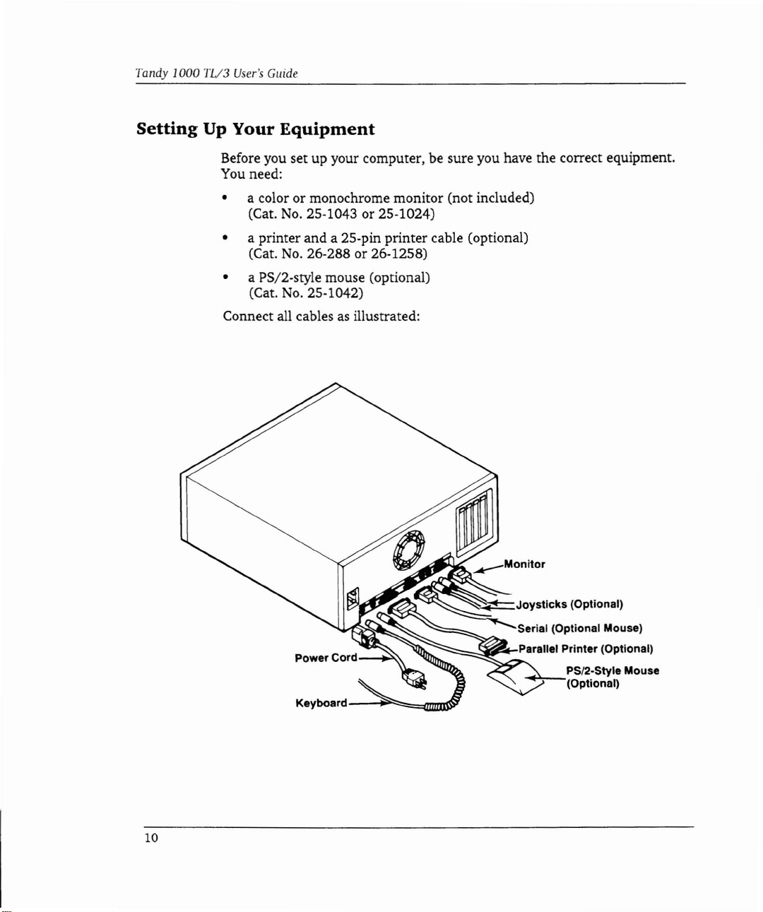
Setting
Up Your
Equipment
Before you set up your computer, be sure you have the correct equipment.
You need:
• a color or monochrome monitor (not included)
(Cat.
No.
25·1043 or 25-1024)
• a printer and a 25-pin printer cable (optional)
No.
(Cat.
26-288 or 26·1258)
• a PS/2-style mouse (optional)
No.
(Cat.
25·1042)
Connect all cables as illustrated:
10
Keyboard---~~~~~~
.....
Joysticks
~Serial
-""";;;=,..;sl_,.....Parallel Printer (Optional)
(Optional)
(Optional Mouse)
PS/2-Style Mouse
(Optional)
Page 15
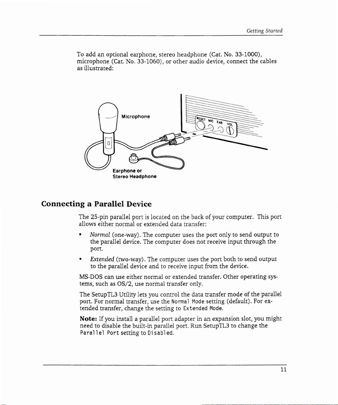
To
add an optional earphone, stereo headphone (Cat.
No.
microphone (Cat.
33-1060), or other audio device, connect the cables
as illustrated:
Earphone or
Stereo Headphone
No.
Getting Started
33-1000),
connectingaParallel
The 25-pin parallel portislocated on the back of your computer. This port
allows either normal or extended data transfer:
• Normal (one-way). The computer uses the port only to send output to
the parallel device. The computer does not receive input through the
port.
• Extended (two-way). The computer uses the port both to send output
to the parallel device and to receive input from the device.
MS·DOS can use either normal or extended transfer. Other operating
tems, such as OS/2, use normal transfer only.
The SetupTL3 Utility lets you control the data transfer mode of the parallel
port. For normal transfer, use the
tended transfer, change the setting to Extended
Note:
need to disable the built-in parallel port. Run SetupTL3 to change the
If you install a parallel port adapter inanexpansion slot, you might
Parallel
Port setting to Disabled.
Device
Normal
Mode
setting (default). For
Mode.
sys-
ex-
11
Page 16
Tandy
1000
TL/3
User's
Guide
Maintenance
Your computerisdurable and needs little maintenance. The following tips
will help you keep your computer running well:
• Read the "Adding Optional Equipment" section before you add options.
• Set the computer up in an area where
•
•
•
•
•
•
•
Tips
it
will be safe from bumps and
collisions.
Install a surge protector between your equipment and the power
supply.
Record important information on the system record.
Keep
liquids away from the equipment.
Use
a disk cleaning kit to clean diskette drives regularly.
Use
dust covers to prolong the life ofyour equipment, especially if it
located in a dusty area.
Use
an antistatic cloth to clean the monitor screen.
Read "Troubleshooting" ifyou have system problems.
is
12
Page 17
Getting Started
Using
the
System
Unit
Controls
Diskette Drive Activity Light Power Button
\ \
\ \
\Ej
\
-"
RESET Button
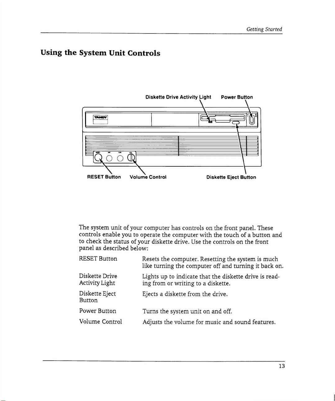
The system unit of your computer has controls on the front panel. These
controls enable you to operate the computer with the touch of a button and
to check the status of your diskette drive.
panel as described below:
"-
Volume Control
Diskette Eject Button
Use
the controls on the front
\
RESET
Diskette Drive
Activity Light
Diskette Eject
Button
Power Button
Volume Control
Button Resets the computer. Resetting the systemismuch
like turning the computer off and turning it back on.
that
Lights up to indicate
or
ing from
Ejects a diskette from the drive.
Turns the system unit on
Adjusts the volume for music
writing to a diskette.
the diskette driveisread-
and
off.
and
sound features.
13
Page 18
Tandy
1000
11/3
User's Guide
Notes
When you use the controls on the system unit, remember:
unit
• do not move the system
not
• do
drive activity light
remove a diskette from the diskette drive when the diskette
is
on
when the computerison
Using
• save your work on a disk before pressing either the
the power button
the
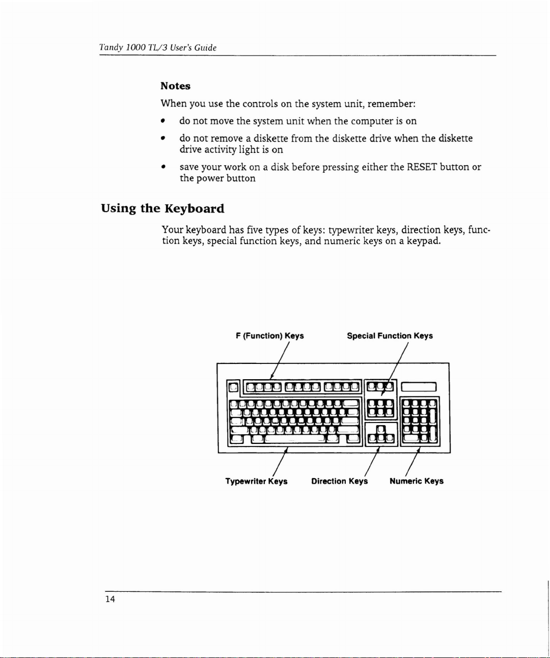
Keyboard
Your keyboard has
tion keys, special function keys, and numeric keys on a keypad.
five
types ofkeys: typewriter keys, direction keys, func-
F (Function) Keys Special Function Keys
/ /
~ I
PIUJug
~
I
~,
Jqq
t
IlJLJ1
Ill
...
7
aH
db
RESET
button
/
I
I
1m
or
14
Typewriter Keys
/ /
Direction Keys Numeric Keys
/
Page 19
The keys on your keyboard work as described below:
Typewriter
Keys
Work like the keys on a typewriter. When you press
and hold a key, the character
ically until you release the key.
Direction
Keys
Work as directed by the program you are using.
With some programs, these keys move the cursor,
highlight a selection, or both.
F (Function)
Keys
Work
as
directed by the program you are using.
Press the appropriate function keys to enable up to
12 functions supported by a program.
as
Special-Function
Keys
Work
Press the appropriate special function keys to
directed by the program you are using.
enable up to nine functions supported by a program.
Getting Started
is
repeated automat-
Numeric
Keys
Work like the keys on a calculator keypad.
Press the four mathematical operation keys to multi-
ply, divide, add, or subtract. The
like the
= key on a calculator; press it to get the
ENTER key works
result of a calculation.
Each light-colored key on the numeric keypad
(except for the 5) works like two keys in one. The characters printed below the numbers indicate functions
that
work as directed by the program you are using.
You press the
to remind you
NUM
LOCK key and the light comes on
that
only numbers and the decimal
point will be typed when you press the lightcolored keys.
off the
NUM
LOCK function,
To
turn
press the key again.
15
Page 20

Tandy
1000
TL/3
User's
Guide
Using
the
Diskette
Before you use the diskette drive, be sure
diskettes for the computer. We suggest
No.
26-418).
The following information should be listed on
• nOKB
• 3l;2-inch
• 80-track
• double-sided
Review "Using the System Unit Controls" ifyou are using diskettes for the
first time.
To
insert a diskette, holditwith
the empty diskette drive as shown:
Drive
that
you have the right type
that
you use Tandy diskettes (Cat.
the
the label side up
diskette:
and
slide it gently into
of
16
Page 21

Getting Started
To remove a diskette, be sure the diskette drive activity lightisoff;
press the diskette eject button.
Diskette
Types
The type of diskette you use in a diskette drive depends on the drive size
and
(3V2-inch or SV4-inch)
high-capacity diskette drives, you
type (high-capacity or standard-capacity). With
can
use both standard-density and high-
density diskettes. Standard-capacity drives use standard-density diskettes.
is
The diskette drive included with the computer
Use
capacity drive.
only standard-density (720KB), double-sided diskettes.
Standard-density SV4-inch diskette drives can hold up to
a 3V2-inch, standard-
360KB
High-density SV4-inch diskettes hold up to 1.2MB ofdata. With a high-
capacity
3J.t2-inch drive, you can use both standard density
and
high-
density (l,44MB) diskettes.
then,
of data.
Drive
Capacity
High-Capacity
Standard-Capacity High-Density no/no
• To
formatastandard-density
need to include
command. See your
capacityofa standard-density
mattedina high-capacity drive.
certain
Diskette
High-Density
Standard-Density yes/yes*
Standard-Density
disketteina high-capacity drive, you will
parametersinyour
operating
system
diskette
Density
operating
documentation for details.
will
not
ReadIWrite
system's
change
yes/yes
yes/yes
whenitis for-
formatting
The
17
Page 22

Tandy 1000
TV3
User's
Guide
Note:
read a standard-density diskette
Astandard-capacity, SV4-inch diskette drive might
that
was written or formatted in a
not
be able to
inch, high-capacity drive.
Taking
CareofYour
Diskettes
Your 3V2-inch diskettes are easy to care
for.
Diskettes work best when they
are stored at a normal room temperature, away from direct sunlight. Label
your diskettes clearly,
To
tain.
avoid writing over important files, you might
you remember
what
information they con-
want
to write protect
so
that
your diskettes.
To
write protect information on a 3V2-inch diskette, hold the diskette with
the label side down. With the point of a pen, slide the write-protect tab into
the open position. When the tab snaps into the open position, a small,
is
square opening
tion from the diskette
left in the upper left corner. You can then read informa-
but
you cannot write information to it. If you
write to the diskette later, snap the write-protect tab back into the closed
so
that
position
the square openingisno longer visible.
Open Position
(Read-Only)
SV4-
want
to
18
Page 23

Using
MS-DOS
MS-DOS 3.3 is the operating system
your Tandy 1000 TL/3.
operating system commands
over
MS-DOS.
ROM
instead of on a diskette or hard drive.
The diskettes shipped with your computer also contain a copy of
3.3. Use the
diskettes you received with the computer. The
a selection on the DeskMate Disk menu. You should make backup copies of
other diskettes
How much you need to know about
use your computer. If
such as creating your own programs, you will need to take the time to
learn the
application programs and DeskMate, you will probably use only a few basic
MS-DOS
Visit a Radio Shack store to choose
you use the
The commands also work faster because they are stored in
MS-DOS
that
MS-DOS
commands.
MS-DOS
MS-DOSisstored in
without
diskcopy
contain important information.
you plantouse advanced operating system features
system and commands. However, to work mainly with
system.
that
controls the basic functions of
ROM,soyou can use the
worrying
command to make extra copies of the
MS-DOS
MS-DOS
about
accidentallywriting
MS-DOS
diskcopy
depends on how you plan to
documentation
commandisalso
that
will help
19
Page 24

Adding
Optional
You
can add optional equipment to your computerasyour computing
needs change. This section explains how to add some of the most popular
options available
Equipment
for
the Tandy 1000 TL/3.
Printers, mice, and microphones and other such equipment are
options -
external option, plug the connector of the option into the appropriate
connector on the front or rear panel of the computer. Refer to "Setting
Your Equipment" in the "Getting Started" section for more information.
Some of the external options
require an adjustment inside the computer. Refer to "Installing the Line
Audio Jumpers" before connecting any audio equipment other
earphone, microphone, or stereo headphone.
Internal options are added inside the computer. This section contains the
instructions for installing the following internal options:
• additional memory
• math coprocessor
• hard drives and diskette drives
• adapter boards
• replacement battery
The TL/3 supports most equipment designed for the
ible computers. However, we recommend installing the equipment
availableatRadio Shack stores. This equipmentisdesigned especially for
your computer and can be installed for you at Radio Shack Service Centers.
Before you install internal options, you need
computer.
options that connect to the outside of the computer. To add an
that
you can use with Music and Sound
for
the real-time clock
IBM
to
remove the cover from the
external
Up
than
an
PC/XT-compat-
Caution:
touch electrical components, be sure
discharge static electricity from your body.
Static electricity can damage electrical components. Before you
to
touch a grounded metal object to
21
Page 25

Tandy.lOOO
TL/3
User's Guide
Removing
the
Computer Cover
Before you remove the computer cover,
ternal devices. Unplug the unit from the electrical outlet. Unplug all cables
and power cords from the back of the computer.
Use a screwdriver to remove the cover mounting screw
computer. Pull the cover away from the back of the unit to release it. Lift
the
cover up
and
away from
the
computer to remove it.
turn
off the computer
and
on
each side of the
any
ex-
22
Place the cover and the screws on a flat surface away from the work area
while you are adding internal options.
Page 26

Adding Optional
Equipment
Main
Logic
Board
The electrical components that make your computer work are located on
the main logic board. The
your main logic board. The components that enable you to use external
audio options are on the satellite board.
The diagrams in this section illustrate sockets, connectors, and jumpers you
might need to find when installing optional equipment.
jumper
A
is
a metal peg
grouped into blocks of three pins on the main logic board. Each pin
labeled.
To
install a jumper, place it over two adjacent jumper pins. This completes
or bypasses a circuit, enabling or disabling a function of the computer.
and
Satellite
satellite board
is
a small plastic cover
that
protrudes from a board. The TL/3 jumper pins are
Board
that
Layout
is
the small board connected
contains metal contacts.
Ajumper
is
to
pin
Installed
23
Page 27

Tandy
1000
'11/3
User's
Guide
Sockets
BackofComputer
and
Connectors
OOJ
DO
'0
.~=~-
Diskette
0
0
C:
00
~
n0
u
b.l
D[j
D
.0
00
c:::::::l
~
c:::::::l
~
c:::::::l
~~ChiP
~=:I
~~~~~
Connector,
(J4)
"'--
Memory
~(U4,
Math
Socket, Pin 1 (U9)
SmartDrive
Pin 1 (J1)
Drive
Pin 1
Expansion
Sockets, Pin 1
US,
U6, U7)
Coprocessor
Connector
24
D D
====i
-.----------,~
=
00
Ufl
R
Real-Time
Clock
Battery
(J3)
Page 28

Adding Optional Equipment
Jumpers
Interrupt
Jumpers
(E16, E17,
E18, E19)
~i----
Diskette Drive
Connector
Select
(E6.
Diskette Drive
Connector
Jumper
Address
Jumper
E7,
E8)
Enable
(E9. E10, E11)
=
ROM
~~_
Size
Select
Jumper
(E1.
E2. E3.
E4, E5)
Headphone/line
Audio
Output
Jumper
(E4,
E5,
E6)
BackofComputer
~D
~
-.-----------.1
CJ
L-I
------JI
g I lo,....--..JI--
=
001
=0
0
D
0
o
'-----,..Satellite Board
••
Microphone/line
Audio
Input
Jumper
(E1,
E2,
E3)
25
Page 29

Tandy 1000 TL/3
User's
Main
Guide
Logic
Board
Jumpers
Jumper
ROM
Size
Select Jumper
Diskette Drive
Connector Address (I/O Ports 3FO-3F7)
Select
Diskette Drive
Connector Enable
Interrupt Jumpers
*Default Setting
tReserved for
Satellite
t
factory use
Board
Jumper
Microphone/Line
Audio Input Jumper enabled
Earphone/Line Audio
Output Jumper
Settings
E2
E1 and
E3
E6
E7
E9
EIO and
E16 and E17 installed HDIRQ=IRQ2
E17
E18
installed
andE4installed
andE7installed Primary
andE8installed
and EIO installed Disabled
Ell
installed
and
E18 installed
and
E19 installed VSYNC=IRQS
Jumpers
Settings
ElandE2installed
E2
andE3installed
E4
andESinstalled
ES
andE6installed
Description
4MB
ROM
enabled*
*
Secondary
(I/O Ports 370-377)
Enabled*
HDIRQ=IRQS*
Description
Line-level audio input
Microphone enabled*
Line-level audio
output
enabled
Earphone enabled*
26
*Default Setting
Page 30

Adding Optional Equipment
Installing
Additional
The Tandy 1000 TL/3 has
Memory
640KBofRAM
supplied by four lOOns, 256KB x
4 memory chips. You can install 128KB of additional memory to increase
the total system memory to 768KB.
To
install additional memory, you will need a
25-1078). The kit contains four lOOns,
tions.
Be
sure to read the instructions before you complete the following
128KB
64KB
x 4 memory chips
Memory
Kit
and
(Cat.
instruc-
stallation procedure:
I.
Remove one of the memory chips from the special antistatic package.
2.
Find the four memory chip sockets on the main logic board. These sockets are labeled
U4,
U5,
U6,
and
U7.
Refer to "Main Logic Board
and
Satellite Board Layout" to locate the sockets.
3.
Find the notch or dotonthe chip. (Check the kit instructions.)
4.
Align the notch or dot on the chip with the notch on the memory chip
socket on the main logic board.
BackofComputer
No.
in-
Pin 1
Memory Expansion
Chip and Sockets
5.
Gently press the memory chip into the socket.
6.
Install the three remaining chips in the memory socketsonthe main
logic board.
27
Page 31

randy
1000
nl3
User's
Guide
InstallingaMath
Computer-aided design packages, spreadsheet packages, and other applications
that
coprocessor takes over the mathematical processing to free the
other uses. Your computer requires an 8MHz, 80287
No.
(Cat.
logic board.
Caution:
touch the math coprocessor, be sure to touch a grounded metal object to
discharge static electricity from your body.
Carefully read the instructions before you place the coprocessor into the
socket. Incorrect orientation or installation of the coprocessor can damage
the coprocessor or the socket. Radio Shack Service Center technicians
install optional devices if you choose not todoso
o
Coprocessor
require many arithmetic calculations can tie up the
math
900-2191). The
Static electricity can damage electrical components. Before you
OJ
0 00OIIIIJ
~
~
math
coprocessor socketislocated on the main
Back of Computer
0 0 [[}O 0 =
<;:;JD
=
D
~~
~
D
===
00
c:::J
yourself.
0 D0 0
CPU.
Amath
CPU
for
coprocessor
0=0
= 0
~
DDD~DD
0
DODD
~I
-~J!o~~
will
28
o
oDD
~
~~~m==JD:Do
~:;;:;~~~fo-
Math Coprocessor
and Socket
p'in 1
Page 32

Adding Optional
Use
the following procedure to install a math coprocessor on the main logic
board of your computer:
1.
Orient the math coprocessorsothat the notch in the end of the
coprocessor aligns with the notched end of the socket, as illustrated:
Notch
~:ii:::::::~
Coprocessor
Socket
2.
Press the math coprocessor into the socket, taking care not to bend or
touch the metal pins.
Notch
Equipment
f:::~::::::::::::1
Installed
Coprocessor
29
Page 33

Tandy 1000 TL/3
User's
Guide
Installing
Additional Drives
Your TL/3 has one 3V2-inch
tion, you can install one or more of the following storage devices:
• a 3V2-inch diskette drive or SmartDrive in the drive platform, the
removable pan located to the left of the factory-installed diskette drive.
You
can also install a 3V2-inch diskette drive in the 5V4-inch drive
bay, using a 3V2-inch to SV4-inch Disk Drive Adapter (Cat.
You
1076).
can order the SmartDrive adapterata Radio Shack Store
(from Tandy National Parts).
• a 5V4-inch diskette drive in the 5V4-inch drive bay
Note:
To
install a SmartDrive (Cat.
have installed devices in both the drive platform and the drive bay, you can
purchase a SmartDrive mounting bracket. Using this bracket, you can
install the SmartDrive in the slot on the bottom ofthe computer. The
is
mounting bracket
availableatRadio Shack Stores (from Tandy
National Parts). The SmartDrive connector on the main logic board supports one SmartDrive.
The TL/3 supports most
drives. However, we recommend the Tandy diskette drives and hard drives
(SmartDrives) available at Radio Shack stores. These drives are designed
especially for your computer.
If you are installing a diskette drive, remove the appropriate panel from the
computer cover
as
illustrated:
nOKB
IBM
diskette drive already installed. In addi-
No.
25-1045 or 25-1046) when you
PC/XT·compatible diskette drives and hard
No.
25-
30
Page 34

Adding Optional
To
remove the 3V2-inch panel, press down on the center tab on the inside
is
of the cover. This panel
replaceable.Toremove the 5V4-inch panel, press
down on it from the outside of the cover. The 5V4-inch panel
Equipment
is
not replace-
able.
Read the appropriate proceduresinthis section to install optional storage
devices in your Tandy 1000 TL/3.
Before installing a hard drive card in the computer, you must attach a sup-
is
port bracket to the hard drive card. This bracket
is
stores. Installing a hard drive card
similartoinstalling an adapter board.
availableatRadio Shack
For more information about preparing a hard drive card for installation,
refer to the installation guide included with the hard drive card.
31/2-Inch
Drive
To
Diskette
DriveorSmartDrive
Installation-
Platform
install a 3v2-inch diskette drive or SmartDrive in the drive platform of
the computer:
1.
Use
a screwdriver to remove the two front screws that attach the drive
platform to the computer. Slide the platform toward the back of the
computer. Remove the platformbylifting it up and out of the computer.
........,::;_---
Drive Platform
31
Page 35

Tandy
1000
TL/3
User's
Guide
2.
Use
the four screws from the drive installation kit to attach the drive to
the platform as shown:
32
Note:
tion shows screw installation for a 3V2-inch diskette drive.
SmartDrive, use the holes on the second row
There are two rows of holes on the drive platform. The illustra-
To
that
correspond to the
mounting holes on the drive. Refer to the drive installation guide for
more information.
3.
Use
the two screws you removedinStep 1 to attach the drive platform
and the drive to the computer.
4.
Refer to the installation kit documentation to connect the cable to the
drive, using the correct Pin 1 alignment. Connect a computer power
cable to the drive, if necessary.
5.
Attach the remaining cable connector to the diskette drive connector or
the SmartDrive connector on the main logic board. Refer to "Main
Logic Board and Satellite Board Layout" to find Pin 1 of the SmartDrive
connector or diskette drive connector on the main logic board.
install a
Page 36

Adding Optional1::qllipment
51/4-Inch
To
1.
Diskette
install a SV4-inch diskette drive in the drive bay of the computer:
Press the latches of the two drive mounting rails in firmly. Slide the
rails out of the SV4-inch drive bay. Remove and discard the grounding
clip screws.
2.
Use
a small screwdriver and the four screws included with the
diskette drive to attach the rails and the grounding clips to the drive:
Drive
~"
Installation-51/4-Inch
Drive
Bay
.
/
/~
Grounding Clip
Mounting Rail
3.
Slide the drive mounting rails and the diskette drive approximately
halfway into the drive bay. Attach the drive and power cables as
directed in the diskette drive installation guide.
4.
Slide the drive into the bay until the latches snap into place.
Run theSetupTL3 utility to specify the type ofthe new diskette drive.
5.
33
Page 37

Tandy 1000
TV3
User's
Guide
Accessing
a Drive
Each diskette drive,
drive identifier
the
alphabet
drives
installed diskette drive, type:
followed by a colon. Use drive identifierstoaccess individual
and
partitions. For example, to access a disketteinthe
a:
The
indicatorlightonthe
drive is being accessed. The following MS-DOS
A>
This
prompt
mationonthe
The first diskette drive in
ette drive
when
table
lists
Drives
indicates
is
always DriveB.Identifiers for
you install additional drivesorpartitionahard
the
Installed
hard
drive,
and
drive
partitioninyour
thatisassignedbyMS-DOS. A drive identifierisa
diskette drive flashes to
that
you
can
type MS-DOS
diskette in
drive identifierstouse
the
drive.
the
systemisalways Drive A
other
when
you install devices as shown:
Drive
Identifiers
Third
Diskette
Drive
ROM
Drive
computer
factory-
show
that
the
promptisdisplayed:
commandstoaccess infor-
and
the
drives sometimes
drive. The following
SmartDrive
has
letter
diskette
second disk-
change
Drive
Partition
a
of
34
One
or two
diskette drives
Three diskette drives
One
or two diskette drives
and a SmartDrive
Three diskette drives and
a SmartDrive
*To
install a SmartDrive (Cat.
installed devices
form,
ordered
*
in
you
can purchase a SmartDrive mounting bracket.
from
both the SV4-inch drive bay and the 3l,;2-inch drive plat-
Radio
Shack Stores (through Tandy National Parts).
No.
25-1045 or
None
c:
None
D:
c:
D:
D:
E:
25·1046
None
None
C:
c:
only) when you have
This
bracket can be
None
None
E:
F:
Page 38

Adding Optional Equipment
Initializing
The Tandy 1000 TL/3 supports the installation of one
a SmartDrive
20MBor40MB
SmartDrive. After installing the drive, you must initialize it for use with the
computer.
The initialization
DeskMate user interface.
the initialization. Follow the directions below to initialize the SmartDrive:
1.
Label the blank diskette "SmartDrive Installation Backup Diskette."
2.
Tum
on the computer and insert the blank diskette into the 3V2-inch
diskette drive (Drive
3.
Press
TAB
highlightHINSTALL>PDM.
4.
Follow the prompts displayed on the screen to initialize the drive.
When the program asks you to continue, press
stop, press
After you
~omplete
Backup Diskette in a safe place. You will use the diskette if you ever need
to re-initialize the drive.
Your SmartDrive can be accessed as Drive
Drive, you will need to format the drive. If you installed a
Drive you will need to format and partition the drive. Refer to the
documentation included with the SmartDrive. For more information about
installing application programs on the drive, refer to the application
documentation.
is
done from the desktop, the first screen displayed in the
You
will need a blank
A).
until you highlight
the
PROGRAMS
720KB
diskette to complete
box. Press~until you
Press ENTER.
ENTER. If you need to
ESC to cancel.
the initialization, store your SmartDrive Installation
C.
If you installed a 20MB Smart-
40MB
Smart-
3S
Page 39

Tandy 1000
TL/3
User's
Guide
Installing
Expansion
You
can install uptofour
Adapter
IBM
Boards
PC/XT-compatible (8-bit) expansion
adapter boards in the expansion slots ofyour Tandy 1000 TL/3. These
adapter boards can be up to 10 inches long. Many popular expansion adapter
boards are availableatRadio Shack stores. One type of adapter board,
called a hard drive card, provides storage like a hard drive.
1.
Choose the expansion slot into which you wish to install the adapter
board. For a hard drive card, you should select Slot 4, the expansion
slot closest to the power supply.
2.
Remove the screw that secures the slot cover to the back panel of the
computer. Slide the slot cover up and out of the computer.
Note:
Ifyou are installing a hard drive card, you must install a sup-
port bracket. Follow instructions included with the equipment.
3.
Press the adapter board into the expansion slotasshown:
Slot Cover
/andScrew
36
4.
Use
the screw you removed in Step 1tosecure the adapter board
the back of the computer.
at
Page 40

Adding Optional Equipment
Installing
the
Line
Audio
Two blocks ofjumper pins are located on the satellite board of the Tandy
1000TL/3. You must reposition the jumpers that are installed on these pins
to enable some audio input and output features for Music and Sound. Refer
to "Main Logic Board and Satellite Board Layout" to locate the jumper pins
on the satellite board and for more information about installing jumpers.
Microphone/Line
The Microphone/Line Audio Inputjumper pins are labeled
Installing the jumper for these pins enables you to select the type of device
that
can be connectedtothe microphone connector, labeled
back panel. The jumper installed on these pins enables you to input music
and sounds from other audio devices through the computer. For example,
you can connect a microphone to the connector to input your voice through
the computer.
By
default, the Microphone/Line Audio Input jumperisinstalled in the
microphone position, on Pins
microphone.
able the connection of a microphone), install the jumper in the line-level
audio input position, on Pins
audio position, you can connect a radio, tape recorder, or other device with
a line-level output.
To
Jumpers
Audio
enable the connection of a line-level audio device (and dis-
Input
E2
and
El
and
Jumper
El,
MIC,
E3,
to enable the connection ofa
E2.
With the jumper in the line-level
E2,
and
on the
E3.
•
D
Microphone
(Default)
El
::
Position
D
:~
E3
Line·Level Audio
Position
Input
37
Page 41

Tandy
1000
TL/3
User's
Guide
Earphone/Line
The Earphone/Line Audio Output jumper pins are labeled E4,
The jumper on these pins enables you to output music and sounds from the
computer to another audio device. For example, you can connect an earphone or a stereo headphone to the connector labeled
the computer. Music and sounds from the computer are outputthrough the
earphone
the
speaker.
By
default, the Earphone/Line Audio Output jumperisinstalled on Pins
and
the jumperon Pins
a headphone and enable the connection of a line-level audio output.
so
EAR
connector, music and sounds are output through the built-in
E6,
enabling the connection of an earphone or a headphone. Install
Audio
that only you can
D
Output
E4
andESto disable the connection of an earphone or
•
E4
::
Jumper
EAR
on the front of
hear
them. When no deviceisplugged into
D
::
• E6
ES,
and
E6.
ES
38
Earphone/
Position
Headphone
(Default)
Line-Level
Output
Position
Audio
Page 42

Internal Real-Time Clock
The real-time clock maintains the system time and date. An internal battery
powers the clock, enabling it to maintain the correct time and date when
the computer power
at
available
Radio Shack stores.
is
off.
Replacement batteries (Cat.
Adding Optional
No.
25-1033) are
Equipment
Replacing
the
Battery
The clock battery should last at least three years with normal use. When it
fails, the computer will not retain time and date information correctly.
If the computer does not restart when you turn it on or reset it, it could
dicate that the batteryisweak or dead. Before replacing the battery, refer
Logic
to "Main
Board and Satellite Board Layout" to locate the battery
socket.
do
If you
not want to replace the battery yourself, a service technicianata
Radio Shack Service Center will replace it for you.
To
replace the battery:
1.
Gently lift the battery clip and remove the old battery from the socket
on the main logic board.
in-
39
Page 43

Tandy
1000
TL/3
User's
Guide
2.
Position the new battery with the positive side
illustrated:
3.
Use
SetupTL3 to enter and store the system time and date.
(+)
up and insert it
as
Replacing
the
Cover
When you finish adding internal options, place the cover over the front of
the unit. Slide it back until it snaps into place
at
the back of the computer.
Secure the cover with the two screws you removed previously.
40
Page 44

Setting
System
Options
The TL/3 runs according to the settings you choose when you
SetupTL3 utility. The computer has original settings called
You can use SetupTL3 on diskette to change the default settings to better
suityour system needs. This section explains
utility.
SetupTL3 lets you change the settings for the following system information:
• whether your computer runs diagnostic checks each time you
• whether the computer prompts you for the time and date each time
tum
you
• the video display mode for the monitor connected
• the data transfer mode of the parallel port
• the number of disk buffers used by
• the maximum number of files
• whether the system should execute the autoexec.bat
file automatically
• whether the computer starts from the programs built into
a diskette or hard drive
• whether DeskMate or
puter from
• which drive you want to use as the primary (system default) drive
it on or reset it
ROM
MS-DOS
that
will be started when you start the com-
when
and how to
MS-DOS
can be opened under
run
the
default settings.
run
the
tum
MS-DOS
and/or
config.sys
ROM
or from
it on
• whether the system
• how fast the
You
can
run
puter. The DeskMate Setup Accessory enables you to perform some setup
operations from a DeskMate menu. Refer to your DeskMate documentation
for more information about the DeskMate Setup Accessory.
CPU
SetupTL3 from the utilities diskette included with the com-
is
set for the connection of a PS/2-style mouse
runs
41
Page 45

Tandy 1000 TL/3
User's
Guide
Running
the
SetupTL3
The first time you
whether
ample, if you connected a PS/2-style mouse,
MOUSE
Be
you install a diskette drive, use one of the 0;
the setting
diskette
change the setting
to change the other fields displayed on the SetupTL3 screen.
When you select a field on the SetupTL3 screen, a briefdescription
field
setting, press
displayed.
To
a:
At
tom ofthe screen explain how to change settings and move from one field
to another.
The following sections explain each setting
tions to determine whether you need to change the default settings.
the default settings are appropriate for your computer. For
PORT
DEVICE
sure to
and press ENTER to access the diskette drive, if necessary.
theA>prompt, type setupTL3 and press ENTER. The directionsatthe bot-
run
that
or
hard
is
displayed at the bottom of the screen. For more information about a
run
SetupTL3, insert the Utilities Diskette into the diskette drive. Type
Utility
turn
on the computer,
setting from
SetupTL3 ifyou install additional drives in your computer. If
describes the
drive
thatisaccessed when you
of
the
FI
after making a selection. The on-line help for
NOT
new
Start-up
run
SetupTL3 to determine
ex-
run
SetupTL3 to change the
INSTALLEDtoINSTALLED.
sketteDr;vefields to select
diskette drive. If you need to change the
turn
on the computer,
Dr;vefield. You will probably
on
the screen. Read the explana-
that
not
need
of
field
the
is
42
Time
Displays the system time. Hours, minutes, and seconds are displayed in the
military format.
tom of the screen.
Date
Displays the system date. The month, day, century, and year are displayed
on
the screen. Follow the instructions at the bottom ofthe screen to change
the system date.
To
change the system time, follow the directionsatthe bot-
Page 46

Setting System Options
Start-Up
Select
ette. Otherwise, leave
built
start
from MS·
Video
Select
black
settingatCOLOR.
otherbypressing
Operating
damage
monochrome
Mouse
Select
leave the setting
CPU
Device
DISKtostart
into ROM. If
from DeskMate in
DOS
Display
MONOCHROMEifyour
and
white. If
the
the
Port
INSTALLED
the
in ROM.
Mode
You
CTRL+ALT+SHlFT+V.
computerinthe
monitor. Be sure to press
monitor
Device
if you have
at
Speed
the
computer
the
settingatROMtostart
Auto-Des
ROM
your
can
displaysanimage
the
default,
when
monitor
monitor
also
change
connected
kMate
wrong
NOT
from a
displays more
programona
from oneofthe
fieldisenabled,
you
turn
it on. Otherwise, it will
can
display only two colors,
than
from one video display
video mode for
CTRL+ALT+SHIFT+V
that
does
a PS/2-style mouse. Otherwise,
INSTALLED.
hard
diskordisk-
programs
the
computer
such
two colors, leave
modetothe
your
monitor
if
your
not
fill
the
entire screen.
will
start
as
the
can
Select
SLOW
(5 MHz) to useanapplication
the
FAST
(lOMHz) speedofthe
Start-Up
Select
you
a faster
Serial
Select
is
PRIMARY,orCOMI.
Diagnostics
ENABLE
turn
it on.
startup.
Port
SECONDARY
ifyou
want
DISABLEisthe
to use
COM2asthe
Select
that
does
computer.
the
computertorun
default setting. The default
DISABLEtoturn
serial
FASTisthe
diagnostic tests
port
address. The default
off
not
default setting.
the
useofthe
work
setting
properly
each
time
results in
setting
serial port.
with
43
Page 47

Tandy 1000
TL/3
User's
Guide
Parallel
Choose
Port
Nonnal
Mode,
the default setting, to send output to the parallel port.
Most printers use this setting. The computer will not receive input data
Di
through the port with this setting. Select
parallel port.
Mode.
The computerwill send output and receive input through the parallel
To
use normal data transfer, change the setting to Extended
sab1e to
tum
off the use of the
portwith this setting.
Diskette
Drive
0
Choose a setting to specify the diskette drive type of the first diskette drive
installed in the system. The following settings describe the types of diskette
drives
that
can be installed:
None
3lr2-inch, 720KB
3lr2-inch, 1.44MB
5V4-inch, 360KB
5V4-inch, 1.2MB
Leave the settingatthe default diskette drive type (3V2-inch,
nOKB)
for
the factory-installed drive.
Diskette
Drive
1
Choose a setting to specify the diskette drive type of the second diskette
drive installed in the system. The following settings describe the types of
diskette drives
that
can be installed:
None
3lr2-inch, 720KB
3lr2-inch, 1.44MB
5V4-inch, 360KB
5V4-inch, 1.2MB
44
Leave the setting at
None
if you have not installed a second diskette drive.
Page 48

Setting System Options
Diskette
Drive
2
Choose a setting to specify the diskette drive type of the third diskette drive
installed in the system. The following settings describe the types ofdiskette
that
drives
can be installed:
None
3l,t2-inch, 720KB
3l,t2-inch, 1.44MB
5V4-inch, 360KB
5V4-inch, 1.2MB
Leave the settingatNone
Start-up
If you chose the
Drive
DISK
responding to the drive from which you
The
MS-DOS
identifier for this drive will be Drive
if you have not installed a third diskette drive.
as the Start-up Device, choose the number cor-
want
to load
MS-DOS(0or 1).
A.
Auto-DeskMate
Select
ENABLE
ROM.
Othetwise, the system starts with
to start the computer from the DeskMate program built into
MS-DOS.
Date
and
Time
Prompts
Select
YES
if you
want
the date and time prompts to appear each time you
start the computer with
time or leave each field blank and press
the real-time clock. When
from the real-time clock and does not display the
prompt at system startup.
Check
for
Config.sys
MS-DOS.Atthe prompt, enter the correct date and
ENTER to use the time and date of
NOisselected, the system uses the time and date
MS-DOS
date and time
NOisthe default setting.
on
Drive
Some programs require you to include certain software configuration commands in the
turn on or reset the computer. When
a program, you must let the computer know where to find the
config.sys
file. These commands are processed each time you
config.sys
commands are required for
config.sys
file.
45
Page 49

Tandy 1000
TL/3
User's
Guide
If you selected
DRI
VE
Cto search for the
tum
on or reset the computer. Otherwise, leave the settingatthe default
setting,
file on either drive when starting from the programs in
If you selected
check for
NO.
WhenNOis
config.sys
ROM
as
the start-up device, change the setting to
config.sys
file
on either of these drives when you
selected, the system does not check for a
ROM.
DISK
as
the start-up device, the computer will automatically
on the diskette or hard drive selected as the start-up
DRIVE
config.sys
Aor
drive.
Check
The commands in the autoexec.bat
for
Autoexec.bat
on
Drive
file
are processed each time you
tum
on
or reset the computer. Some programs require that you include certain commands in the autoexec.bat configuration
DRIVE
or
Drive Cwhen you
ting
Maximum#of
Cifyou wanttosearch for the autoexec.bat file on Drive A or
tum
on or reset the computer. Otherwise, leave the set-
at
NO,
the default setting.
Open
Files
(8-23)
Set this value to the maximum number of files allowed open under
DOSinROM.
Refer to the documentation included with any applications
file.
Change the setting to
DRIVE
MS-
A
you use for information about the number of files needed. The default set-
is
ting
10 open files.
46
NumberofDisk
Buffers
(2-17)
Set this value to the maximum number of disk buffers required by the
programs you run. Refer to the program documentation for the disk buffer
is
requirements. The default
10 buffers.
Page 50

Troubleshooting
This section describes some of the problems you might have with the
Tandy 1000 TL/3 and explains how to solve them.
Problem
Possible
Solutions
Blank screen
No
printer
response
Optional
equipment
not
working
No
keyboard
response
that
Check
Check the brightness or contrast control.
Check the cable connections.
For a monochrome monitor, press
SHIFT+V to switch between color to monochrome
video mode.
Check
Check the printer cable connections.
Check
control).
Check the positions ofpaper
Check the settings of the switches on the printer.
Refer to the printer documentation.
Be
sure the application program you are usingisset
for the correct printer type. Refer to the application
program and printer documentation.
Check the installation ofthe device. Refer to the
"Adding Optional Equipment" section of this
manual and the device documentation.
Check the keyboard cable connection
the computer.
the monitoristurned on.
that
the printeristurned on.
that
printerisready (on-line/off-line
and
CTRL+ALT+
ribbon.
at
the back of
47
Page 51

Specifications
System
Unit
Processor
Size
Power
Power
Heat
Environment
Air
Humidity
Length:
Width:
Height:
Weight:
requirements
consumption
output
temperature
Operating
Storage
Operating
Storage
Intel 80286,
14
in. (35.4 em.)
lsVz
in. (39.4 em.)
sV4
in (14.0 em)
17V4lbs. (7.82
120
VAC,
130
W,
342
Btu/hour
10°C to 35°C
-40°C to 66°C (-400P to 150°F)
20% to 80% non-condensing
10% to 90% non-condensing
10/5
MHz
Kg)
60Hz
l.sA, 110 to 12sV
(maximum)
(sOOPto9s0P)
AC
Microphone/Line-Level
Microphone
Line-level
input
Input
input
Earphone/Line-Level Output
Headphone
(through
Line-level
EAR
output
output
connector)
Full scale (20mV into
Full scale (2.0V into 100KO)
32smW
0.8V
RMS
typ into
into
80
47m
10m)
load
load
49
Page 52

Tandy
1000
TL/3
User's
Guide
Connector
Pinouts
The following tables indicate the pin functions to the video connectors.
Video Port Connector
Pin
Pin
1 Ground
2 Ground
3 Red Video
4 Green Video
5 Blue Video
6 Intensity
7 Green Video
8 Horizontal Synch
9 Vertical Synch
Monitor voltage levels are TTL-standard.
Monochrome-type monitors use Green Video for all video input and ignore
Red Video and Blue Video.
RS-232C Serial Port Connector
Pin
Pin
1 Carrier Detect
2 Receive Data
3 TransmitData
4 Data Terminal Ready
5 Signal Ground
6 Data Set Ready
7 Request
8 Clear
9 Ring Indicator
Assignments:
Function
Assignments:
Function
To
To
Send
Send
:
:.
9
3
••
8
2
••
~
1
••
so
Page 53

Specificatiolls
Parallel
1/0 Port Connector
Pin
Assignments:
Pin
Function
1 Strobe
2 Data Bit 0
3 Data Bit 1
4 Data Bit 2
5 Data Bit 3
6 Data Bit 4
7 Data Bit 5
8 Data Bit 6
9 Data Bit 7
10
11
12
13
14
15
16
17
18-25 ground
ACKNOWLEDGE
BUSY
PAPER
SELECT
AUTO
ERROR
INITIALIZE
SELECT
END
FEED
IN
Joystick Port Connectors
~
12.
11
10
:
7
6
5
4
3
2
1
•
••
••
::
••
••
•
••
••
••
••
.::1
l
J18.25
17
16
15
14
Pin
Assignments:
Left
Joystick
Pin
Joystick port locations are controlled through lIO ports 200-207.
Function
1 Position 1
2 Position 2
3 Ground
4 Switch 1
5 Power
6 Switch 2
Right
Joystick
Pin
Function
1 Position 3
2 Position 4
3 Ground
4 Switch 3
5 Power
6 Switch 4
51
Page 54

Tandy
1000
TL/3
User's
Guide
Keyboard
720KB
and
PS/2-Style Mouse Connectors
Pin
Assignments:
Pin
Diskette
Function
1 Data
2 Reserved
3 Ground
4
+5
Vdc
5 Clock
6 Reserved
Drive
Unformatted
Formatted
capacity
Numberofheads
Numberofcylinders
Average
access
Track-ta-track
Motor
Rotation
starting
speed
Media
capacity
time
access
time
time
1MB
nOKB
2
80
93 ms (including settling time)
4ms
500ms
300
rpm
3V2-inch, double-sided, 80-track
52
Page 55

Glossary
adapter
autoexec.bat
batch
file
chip
circuit
command
config·sys
connector
An
optional board that lets the computer perform additional specialized functions. Some adapters enhance built-in features of the computer. A memory expansion adapter,
memory so that you can run more software applications.
Aspecial batch file that contains
executed when you
programs and devices will require you
After you turn on or reset your computer, it will automatically search
for the autoexec.bat
that
Afile
batch file (the portion before the
MS-DOS
can be run automatically
Asmall device containing several circuits. Achip has pins that must
be aligned properly with the corresponding holes in a socket on a
board. The chips on the main logic board of a computer contain the
circuits that make the features of the computer work.
chips to the main logic board to improve the performance of the computer. For example, installing memory chips on the main logic board
provides additional
Apath that electricity will follow. Circuits on the main logic board
enable your computer
An
example, when you type the
ENTER, it copies files from one memory location to another.
Aspecial
environment used by
configure your system for
devices require you
turn on or reset the computer, it automatically searches for this file
specified in the Setup utility.
Asocket that lets you connect devices to a board in the computer.
Connectors can be accessed on the inside as wellasthe outside of the
computer. For example, the keyboard connector lets you to connect a
keyboardtothe back panel of the computer. The diskette drive connector on the main logic board lets you connect an optional diskette
drive.
contains
prompt runs each command in the file. Batch file commands
order that a computer processes, or carries out, immediately. For
file
reset
or turn on the computer. Some application
fileasdirected by the Setup utility.
MS-DOS
RAMtothe system.
that contains information about the operating system
to
commands. Typing the name of the
at
reset or startup.
to
work.
MS-DOS
MS-DOS.
MS-DOS.
add commands to the
for
example, provides more
MS-DOS
.bat extension)
The commands in the
files and commands to be
to
add commands to this file.
at
the appropriate
You
copy
command and press
config.sys
Some application programs and
config.sys
file. When you
can add
file
as
53
Page 56

Tandy 1000
TV3
User's
Guide
CPU
default
diskette
diskette
EEPROM
EMS
extended
memory
expanded
memory
expansion
adapter
expansion
file
extension
drive
slot
Central processing unit. The chip
that
contains circuits to perform
arithmetic, logic, and control operations. These operations enable the
computer to execute instructions.
An option or value that
is
assumed if no other optionisspecified. For
example, if you do not use the Setup utility to specify a monochrome
COLOR
monitor, the computer uses the color monitor setting. The
is
the default.
ting
Around, flat object
thatiscoated with magnetic material and
enclosed in a protective plastic cover. Diskettes store computer
structions (programs) and data (work files).
You
can write to and
set-
in-
read from a diskette by inserting it in a diskette drive.
An electronic device for storing (writing) and retrieving (reading)
data on a diskette. Most diskette drives are either the SV4-inch or
31.12-inch
size. High-capacity diskette drives use both high-density and
standard density diskettes. Standard-capacity diskette drives use
standard-density diskettes.
Electronically Erasable Programmable Read-Only Memory. This
is
memory
built into a chip on the main logic board of the computer.
The chip can be electronically reprogrammed or erased.
to
Expanded Memory Specification. Used
puter circuitry designed to support the use of extended memory
describe software and com-
as
panded memory. See extended and expanded memory.
The memory above
1MB
(l024KB). Can be used as expanded
memory with expanded memory support.
Memory used to expand the amount of memory
MS-DOS.
by
MS-DOS
The LIM Expanded Memory Specification 4.0 allows
to access up to
32MB
of memory instead of the 640KB it
that
can be accessed
could access originally.
Adevice that has chips
and/or
circuitry that expand the features of
the main logic board of a computer. Expansion adapters must be installed in expansion slots.
Aslot in which you can install an expansion adapter. The slot
is
posi-
tioned to connect the adapter to the main logic board.
The last three digits of a filename, preceded by a period. Many
to
filenames that you type
.exe
file
extension.
run programs (executable files) have the
ex-
54
Page 57

hard
drive
IDE
joystick
kilobyte
LIM
main
(KB)
logic
board
math
coprocessor
megabyte
memory
Astorage device that holds large amounts of data. For example, a
20MB
SmartDrive can hold more data than twenty-five
diskettes.
Integrated Drive Electronics. A special type of hard disk drive
you store and use large amounts of data quickly. Tandy SmartDrives
are
IDE
drives.
Ahandle you can move to
give
instructions to a computer. With many
computer games, moving a joystick causes a figure on the screen to
move in the same direction.
is
Specifies an amount of memory. One kilobyte
Lotus/Intel/Microsoft. Used to refer to the
equal to 1024 bytes.
LIM
Expanded Memory
Specification jointly developed and sponsored by Lotus, Intel, and
Microsoft.
The large board inside the computer. The main logic board
brain of the computer; it contains the components
that
puterwork.
Aspecial chip that can be installedtowork with the processor
on the main logic board. Amath coprocessor helps the processor by
performing some of the mathematical calculations required by math-
as
graphics programs.
is
equal to 1,024KB
(MB)
intensive applications such
Specifies an amount of memory. One megabyte
or 1,048,576 bytes.
That portion of a computer that stores information. Memory
provided by chips on the main logic board. See
RAM
Glossary
nOKB
that
is
the
make the com-
(CPU)
is
and
EEPROM.
lets
modem
mouse
on-line
operating
system
option
Modulator-demodulator. A device that changes computer data into
that
signals
travel through telephone cable. Amodem also converts
signals back into computer data. Amodem lets you communicate
with computers in different locations.
A device that lets you to control the movements of the cursor on the
screen.
In direct communication with the computer or other equipment. For
example, an on-line help system enables you to access help directly
from the computer.
Aprogram that controls and manages the work performed using the
computer and the devices connected to
One of several courses of action
Devices
that
you add to a computer are also called options.
that
it.
a computer program can take.
55
Page 58

Tandy 1000
TL/3
User's
Guide
port
program
RAM
reset
ROM
video
write
protect
mode
Aconnector on the computer into which options or equipment re-
quired
for
computer operation can be connected. For example, a
serial mouse can be plugged into the serial port.
Instructions for a computer. Application programs, like DeskMate,
can be used to accomplish a variety of tasks.
Random access memory. The work area of a computer. Random
access memory
is
temporary; all work done must be saved to disk
before you turn off or reset the computer.
Action that stops all processing and returns a computer to its original
condition. After a reset, the computer reacts as if you turned it off
and then turned it back on. Press
partial, reset. Press the
RESET
CTRL+ALT+DEL to perform a soft, or
button on the computer to perform a
hard, or full, reset. Resetting the computer can sometimes correct
problems you might have with the computer.
Read-only memory. A type of memory
that
can be read
but
not
altered.
Setting
that
enables the video circuity of your computer to produce
images like those displayed in standard video modes such as the eGA
(Color Graphics Adapter) mode.
Action that prevents the computer from writing information to a disk.
For example, to write protect a 3V2-inch diskette, press the write-
protect tab into the open position.
56
Page 59

Index
A
abbreviations, 2
activity light, 13
adapter boards, 7
additional drives, 30
auto-DeskMate, 45
autoexec.bat, 46
c
central processing unit
(CPU),3
clock battery, 39
color graphics adapter
(CGA),4
computer cover
removing, 22
replacing, 40
computer system makeup
hardware, 3
software, 3
config.sys, 45
conventions used, 2
CPU
speed, 43
D
data transfer mode
extended, 11
normal, 11
default settings, 41
DeskMate,3
Setup Accessory, 41
direction keys, 15
diskette
care, 18
types, 17
use, 16
diskette drive,
30,52
drive type,
eject button, 13
5,
13, 16,
17,44,45
E
Earphone/Line Audio
Outputjumper, 38
equipment, 3
80287 math coprocessor
socket, 7,
adapter boards, 7, 36
additional drives, 30
color graphics adapter
(CGA),4
diskette, 16
diskette drive,
Hercules adapters, 4
joystick,7
keyboard,
monochrome display
adapters
mouse, 6
Music and Sound, 4, 37
parallel printer, 7
real-time clock, 4
serial, 6
SmartDrive,
environment, 49
expansion adapter boards,
7,36
expansion slot, 36
extended
5,
data
28
5,
16
15
(MDA),
transfer, 11
4
6,
30,
31,35
F
function keys, 15
H
hard drive card, 30, 36
headphone, 38
Hercules adapters, 4
I
initializing a SmartDrive,
35
installing line audio
jumpers, 37, 38
installing additional
memory,
27
J
joystick port, 7
jumpers, 23, 25,
Earphone/Line Audio
Output, 38
main logic board,
Microphone/Line Audio
Input, 37
satellite board,
26
26
26
K
keyboard, 5, 15
L
line audio jumpers, 37, 38
M
main logic board, 23
jumpers, 25
sockets
maintenance, 12
math coprocessor,
maximum number of open
memory
memory chips,
microphone, 37
files, 46
RAM,3
total,27
and
connectors, 24
7,
27
28
57
Page 60

Tandy 1000 TL/3 User's Guide
Microphone/Line Audio
Input jumper, 37
adapters
4,11,
50
(MDA),
4
19,43
monitor, 10,
monochrome display
mouse,6,10
mouse port device, 43
MS-DOS,
Music and Sound, 4, 37
N
normal
data
transfer, 11
number ofdisk buffers, 46
numeric keys, 15
0
operating system,
19,43
optional equipment,
4,
11,
21
p
parallel port,
ports, 50
power button, 13
printer, 10
prompts
date and time, 45
PS/2-style mouse,6,10
7,
11, 44
R
Radio Shack, 21, 28, 30,
36,39
RAM,3
real-time clock, 4, 39, 45
RESET
button, 13
S
satellite board, 23
satellite board jumpers, 26
serial port,
setting system options, 41
setting up, 10
Setup Accessory, 41
SetupTL3, 5, 41
auto-DeskMate, 45
CPU
date, 42
date and time prompts,
maximum number of open
mouse port device, 43
number ofdisk buffers,
parallel port, 44
running, 42
serial port,
start-up device, 43
start-up diagnostics, 43
time, 42
video display type, 43
sockets and connectors, 24
SmartDrive, 30, 35
initializing, 35
installing,
SmartDrive connector, 30
software video display mode, 43
DeskMate,3
MS-DOS,
SetupTL3, 5, 41,
speaker, 38
special-function keys, 15
6,
speed, 43
files, 46
43
44
6,
30, 31
4,11,19,43
specifications
diskette drive, 52
environment,
earphone,
microphone,
monitor,
ports, 50
system unit,
start-up device, 43,
start-up diagnostics, 43
start-up drive, 43
static electricity,
4S
stereo headphone, 11, 38
system date, 42
system time, 42
system unit specifications,
46
49
system unit controls, 13
T
troubleshooting, 47
typewriter keys, 15
U
utilities
SetupTL3,
V
video support, 4
volume control, 13
W
write protect,
49
49
49
50
49
46
28
5,41
18
58
Page 61

System
Record
Use
this system record to keep track of information about your system
tions. Update this information whenever you add new equipment or
memory.
Computer
Serial Number
System
Monitor
Diskette
Diskette
Diskette
SmartDrive
Memory
Additional Memory
Type
Model Number
Serial Number
Drive
Size
(3l;2-inch)
Capacity
Drive
Size (SV4- or 3l;2-inch)
Capacity
Drive
Size (SV4- or 3l;2-inch)
Capacity
Capacity
1 (factory installed)
2
3
(IDE
hard drive)
op-
Expansion
Slot 1
Slot 2
Slot 3
Slot 4
Adapters
59
Page 62

TERMS
AND
SOFTWARE
STORES
I.
CUSTOMER
OBLIGATIONS
A.
CUSTOMER
software
included
capabilities,
B.
II.
L1MITEO
A.
B.
C.
D.
E.
F.
111.
LIMITATIONOFLIABILITY
A.
B.
C.Noaction
D.
IV.
SOFTWARE
RADIO
the
A.
B.
C.
D.
E.
F.
G.
V.
APPLICABILITYOFWARRANTY
A.
B.
Vt.
STATE
The
rights
versatility,
CUSTOMER
Equipment
and
WARRANTIES
RADIO
SHACK
(1)
calendar
year
anginal
CUSTOMER
with
the
Equipmentisfree
These
warranties
company-owned
The
warranties
discovered
during
Radio
Shack
copyofthe
sales
is
limitedtothe
and
sole
expense.
RADIO
SHACK
providedinthis
remedy,inthe
dateofthe
RADIO
a
Radio
Shack
along
with
the
Exceptasprovided
natureonbehalfofRADIO
EXCEPTASPROVIOEO
MERCHANTABILITYORFITNESS
WRITTEN
L1MITEO
Some
statesdonot
CUSTOMER.
EXCEPTASPROVIDEO
OTHER
PERSONORENTITY
OIRECTLYORINOIRECTLYBY"EQUIPMENT"OR"SOFTWARE"
SHACK,
INCLUOING,
PROFITSORCONSEQUENTIAL
"SOFTWARE,"INNO
CONSEQUENTIAL
OR
CONNECTEO
NOTWITHSTANOING
OAMAGES
INCURREOBYCUSTOMEROROTHERS
PARTICULAR
RADIO
SHACK
arising
two
(2)
years
document
for
Some
statesdonot
exclusion(s)
LICENSE
SHACK
grantstoCUSTOMERanon-exclusive,
following
provisions:
Exceptasotherwise
Titletothe
CUSTOMER,
CUSTOMER
onamultiuserornetwork
tobeused
simultaneously.
CUSTOMER
specifically
CUSTOMERispermittedtomake
copies
are
requiredinthe
copytobe
made.
CUSTOMER
Software
for
receiving
copiesofthe
All
copyright
The
terms
and
Equipment
and/or
toathird
party
The
limitationsofliability
or
licensorofthe
LAW
RIGHTS
warranties
which
vary
CONDITIONSOFSALE
PURCHASED
AND
assumes
with
assumes
Software
ANO
warrantstothe
from
that
are
Computer
are
VOIdifthe
the
retail
store,aparticipating
documentorlease
correctionofthe
RADIO
makesnowarrantyasto
paragraph.
eventofa
SHACK
Computer
sales
document.
hereinnoemployee,
WARRANTIES
allow
OAMAGES
WITH
"EQUIPMENT"OR"SOFTWARE"
shall
notbeliable
outofany
after
the
the
EquipmentorSoftware,
allow
may
not
providedinthis
mediumonwhich
but
not
may
use
shall
not
providedinthis
may
resellordistribute
each
one
notices
conditionsofthis
Software
for
leasetoCUSTOMER.
Software
granted
herein
from
statetostate.
FROM
RADIO
SHACK
USA
ONE-YEAR
full
responsibility
the
Equipmentorlicensed
and
other
requirementsofCUSTOMER.
full
responsibility
aretofunction,
CONDITIONSOFSALE
original
the
dateofpurchaseasevidencedbya
any
diskette.
from
manufacturing
only
applicabletopurchases01Tandy
Centers,
merchandise
stated
warranty
defectbyrepair,
SHACK
hasnoobligationtoreplaceorrepair
Softwareislicensedonan
Software
sales
document
Center,aRadio
SHACK.
HEREIN,
RADIO
FORAPARTICULAR
SET
limitationsonhow
HEREIN,
RADIO
WITH
BUT
NOT
LIMITEO
OAMAGES
EVENT
SHALL
ARISING
THE
SALE,
THE
ABOVE
for
claimed
causeofaction
the
limitationorexclusionofincidentalorconsequential
applytoCUSTOMER.
the
titletothe
Software.
Softwareona
system.orone
use,
make,
Software
operationofone
soldordistributed.
Software
from
shallberetainedonall
Warranty
LicensetoCUSTOMERortoatransaction
and
Warranty
and
any
give
the
ANO
RADIO
FRANCHISEESORDEALERSATTHEIR
that
this
for
the
and
for
its
CUSTOMER
disk
cartridge,
defects
retail
stores,
has
periods,
Radio
Shack
agreement.The
the
design,
manufacturing
received
Shack
agent,
franchisee,
SHACK
FORTH
HEREIN,
longanimplied
SHACK
RESPECTTOANY
TO,
ANY
RESULTING
RADIO
SHACKBELIABLE
OUTOFANY
LEASE,
LICENSE,
LIMITATIONS
any
damages
breachofthis
has
accruedormore
whichever
Software
License,
Softwareisrecorded
multiuserornetwork
copyofthis
manufacture,orreproduce
License.
CUSTOMERisexpressly
additionai
copiesofthe
computer
unmodified
The
CUSTOMER.
copiesofthe
are
provisions
manufacturerofthe
o,iginal
CUSTOMER
LICENSEOFTANOY
SHACK
COMPANY-OWNED
LIMITED
computer
separately
condition
and
installation.
that
the
Equipmentisfree
cassette
foraperiodofninety
and
Radio
been
subjectedtoimproperorabnormal
the
defective
franchiseeora
original
CUSTOMER'S
replacement,orrefundofthe
capability,
"AS
IS"
defect,isits
upon
licenseofthe
retail
store,aparticipating
dealerorother
MAKESNOEXPRESS
PURPOSEISLIMITEOINITS
SHALL
HAVENOLIABILITYORRESPONSIBILITYTOCUSTOMERORANY
LIABILITY,
INTERRUPTIONOFSERVICE,
FROM
BREACHOFTHIS
USEORANTICIPATEO
ANO
WARRANTIES,
SHALL
INVOLVEO,
causedbydelayindeliveringorfurnishing
Warrantyortransactions
first
occurs.
paid-Up
licensetouse
applicable
(cassette
system
Softwareispurchased
with
the
copiesofthe
provisionsofthis
Software.
applicableasbetween
herein
shall
Equipment
specific
COMPUTER
COMPUTER
WARRANTY
hardware
purchased
(Ihe
"Soflware")
effectivenessofthe
RADIO
tape,
Shack
item
basis,
repairorreplacement
warranty
NOT
than
copiesofSoftware
Software
Software,
Software
inuretothe
from
SHACK
sales
tape
cartridgeorother
(90)
Equipmenlbythe
franchisees
mustbereturnedtoa
participating
sale
expendable
capacity,orsuitability
without
warranty.
Software.
Radio
personisauthorizedtogive
WARRANTIES,
lasts,sothe
LOSSOROAMAGE
SOLO,
LEASEO,
THE
USEOROPERATIONOFTHE
FOR
LOSSOFPROFITS,ORANY
WARRANTYORIN
USEOFTHE
RAOIO
EXCEEO
THE
under
four
(4)
years
the
copyright
laws
and/or
onlyifeither,
for
prohibited
only
for
but
onlytothe
provided
Software
License
RADIO
Whereby
benefitofRADIO
soldbyRADIO
legal
rights,
EOUIPMENT
ANO
CENTERS,
AUTHORIZED
(the
meets
operating
manufacturing
document.
calendar
original
and
dealersaltheir
Radio
and
exclusive
purchase
items.
within
The
defective
Shack
OURATIONTOTHE
CAUSEOORALLEGEOTOBE
LICENSEOORFURNISHEOBYRAOIO
LOSSOFBUSINESSORANTICIPATORY
SHACK'S
AMOUNT
this
after
damages,sothe
TANDY
Softwareonone
shall
applytothe
diskette)orstored
the
Softwareisexpressly
each
nodeorterminalonwhich
except
from
backuporarchival
CUSTOMER
shall
SHACK
and
Radio
Shack
SHACK.
and
the
RETAIL
LOCATIONS
"Equipment"),
external
days
use.Ifa
Radio
Shack
price,atRADIO
for
The
franchiseeorRadio
ANO
above
ANY
"EQUIPMENT"OR"SOFTWARE."
Warranty
the
for
disassembling
extent
alsobeapplicabletothird
CUSTOMERtoeitherasaleofthe
original
and
the
specificalions,
environmentinwhich
defects
RADIO
SHACK
storage
from
the
dateofpurchase.
customer
Irom
authorized
manufacturing
Shack
Computer
dealer
for
repair,
remedyinthe
useofthe
Software,
original
CUSTOMER'S
thirty
(30)
calendar
Software
shallbereturned
any
ANY
IMPLlEO
OURATIONOFTHE
limitation(s)
"EQUIPMENT"
INOIRECT,
MANNER
LIABILITY
PAlOBYCUSTOMER
Equipment
HEREUNOER
and/or
maybebrought
dateofthe
above
computer,
Software.
(ROM)istransferred
labeledtobe
useonone
computer
the
purposesorif
the
Software
has
purchased
sellsorconveys
SHACK,
the
CUSTOMER
any
copies
capacity,
the
foraperiooofone
warrantstothe
media
included
Radio
Shack
locations,
defect
Center,
along
with
eventofa
defect
SHACK'S
election
except
exclusive
daysofthe
Shack
dealer
warrantiesofany
WARRANTY
may
not
apply
CAUSEO
SPECIAL,
ARISING
OUT
FOR
FOR
THE
Software.
more
Radio
Software.
author,
than
Shack
sales
limitation(s)
subject
for
Software
andasis
additional
allowsabackup
one
copyofthe
parties
such
Equipment
owner
may
have
other
of
is
a
a
as
to
OF
to
OR
OR
OF
or
to
to
use
and/
4190
is
Page 63

I • I
• I
..
 Loading...