

Page 1

TN84%5 i 48-2E
FLEXISLK 9I8g j%)RIVES
MJ' 4 il
[
PRODUCT SPE
/IFICATION AND USER'S MANUAL
Page 2

NOTICE
This document, and the information contained herein, is copyright by Tandon Corporation and
may not be duplicated or reproduced, in whole or in part, without the prior written approval of
Tandon Corporation.
This document is intended to provide the user with detailed information adequate for the efficient
installation, operation, and service of the equipment involved.
However, while every effort has been made to keep the information contained herein current and
accurate as of the date of publication, no guarantee is given or implied as to its accuracy.
Page 3

TM848-1E, TM848-2E
THINLINE™ FLEXIBLE DISK DRIVE
48 TRACKS PER INCH
PRODUCT SPECIFICATION AND USER'S MANUAL
lcllld D I1 CORPORATION
CHATSWORTH, CALIFORNIA 91311
20320 PRAIRIE STREET
o COPYRIGHT 1983 TANDON CORPORATION
Page 4

CONTENTS
Section
Number
SECTION 1 G E N E R A L DE SCRIPTION
Page
Number
Title
1.1
1.2
1.3
1.4
Introduction
Scope Of The Document.. .. . . . . . . . . . . . . . . . . . . .
Purpose Of The Drive
Major Features
Microprocessor Control
Write Protect .
Daisy Chain Capability
Internal Trim Erase
Industry Standard Interface Compatibility .
Activity Indicator .
Direct Drive, Brushless D. C. Motor
Compact Size
Diskette Lever Lock Solenoid
Functional Description
Power On Self- Tests
Physical Description
1-1
1-1
1-1
1-1
1-1
1-1
1-1
1-2
1-2
1-2
1-2
1-2
1-2
1-2
1-3
1-3
1.5
SECTION 2 PRODUCT SPECIFICATIONS
Introduction .
Mechanical Specifications .
Electrical and Operational Specifications
Reliability Specifications
Environmental Specifications .
2-1
2-1
2-1
2-1
2-1
3.4
3.1
3.2
3.3
2.1
2.2
2.3
2.4
SECTION 3 OPERATION
Introduction
Unpacking The Drive
Preinstallation Checkout
Mounting The Drive .
Dust Cover .
Cooling .
Interface Connections
Input Control Lines
Output Control Lines ..
Typical Interface Characteristics
D. C. Power .
Drive Address and Option Strapping
Drive Select (DS1 — DS4)
Head Select Options (Sl — S3 and 1B — 4B) .
Stepper Motor Power (PS, PS*, DS, HL) .
Spindle Motor Control Options (Ml, M3, M4, MOL, MOH, MC1 — MC4)
Ready and True Ready (R and TR)
Lever Lock Options (D, DL, LL, NL)
Disk Change (DC) .
Two-Sided Diskette Installed (2S),
Write Protect (WP and NP) .
Write Current Switch (XC and IC)
Diagnostic Mode of Operation (DM, DL, Ml, M3, M4) .
3-1
3-1
3-1
3-1
3-2
3-2
3-2
3-2
3-5
3-6
3-6
3-8
3-8
3-8
3-10
3-10
3-13
3-13
3-13
3-13
3-13
3-14
3-14
3.5
3.6
Page 5

Section
Number
Page
NumberTitle
3-14
3-14
3-14
3-17
Diskettes
Loading The Diskette
Write Protect Yab .
Diskette Handling and Storage
ILLUSTRATIONS
FIGURES
Figure
Number
Page
Number
n r
1-1
2-1
2-2
4-o
Title
Disk Drive
Disk Drive Outline Drawing
+24 Volt D. C. Current, Configuration 1
+ 24 Volt D. C. Current, Configuration 2
Electrical Interface Characteristics .
Control and Data Timing Requirements
LSI Circuit Board Assembly .
Non-LSI Circuit Board Assembly .
Recording Media
Diskette Care and Handling .
1-4
2-2
2-5
2-5
3-6
3-7
3-11
3-12
3-17
3-18
3-1
3-2
3-3
3-4
3-5
3-6
TABLES
Table
Number
Page
Number
2-1
2-2
2-3
3-1
3-2
3-3
3-4
Title
Electrical and Operational Specifications .
Reliability Specifications .
Environmental Specifications
Drive Interface Lines and Pin Assignments
D. C. Power Connector Pin Assignments ..
Option Patching
Diagnostic Mode Of Operation
2-3
2-6
2-6
3-3
3-8
3-9
3-15
11
Page 6
SECTION 1
GENERAL DESCRIPTION
INTROOU CTION
intelligent t erm i n a l control lers, mic r o-
computers, word processing systems, data com-
munication systems, error logging, program
loading, and point-of-sale terminals.
This document provides required information
in order to evaluate or incorporate Tandon's
disk drive into a system.
Tandon Corporation's Model Nu m b ers
TM848-1E and TM848-2E, eight-inch flexible
drives are full-feature, microprocessor-
controlled drives. They may be installed in
one-half the space normally required for an
eight-inch drive. They are compact data stor-
age devices that use an IBM-formatted, indus-
try standard, eight-inch diskette. Both drives
are 48 tracks per inch recording devices.
The Model TM848 series of drives are capable
of reading an d writ in g in si ngle-density
format on a diskette, using a proprietary
read/write head patented by Tan don. I n
addition, both drives have a double density
capability when Modified Frequency Modula-
tion (MFM) or other appropriate recording
techniques are used. The encoding and decod-
ing of the data is done by the user's controller.
The Model TM848-1E drive uses one side of
the diskette for data s t orage. The Model
TM848-2E drive doubles data storage capabili-
ties by using both sides of the diskette.
1.1 SCOPE OF THE DOCUMENT
1.3 MA JOR FEATURES
MICROPROCESSOR CONTROL
The TM848-1E and TM848-2E drives feature
an onboard microprocessor. This microproces-
sor provides six major features:
1. Buffered seek capabilities..
2. Improved head positioning accuracy
with reduced hysteresis.
3. Write c urrent switching for o ptimal
data recording quality.
4. True Ready signal.
5. Internal diagnostics (strappable).
6. Power On Self- Tests.
WRITE PROTECT
When a write protected diskette is inserted
into the dr i ve, t h e wr i t e el e ctronics are
disabled.
This document contains a description of the
major features, physical and functional speci-
fications, mounting and power requirements,
the interface, and typical timing characteris-
tics of the TM848-1E and TM848-2E drives. DAISY CHAIN CAPABILITY
1.2 PURPOSE OF THE DRIVE
The drive provides the address selection and
gating functions necessary to daisy chain a
maximum of four units at the user's option.
The last drive on the daisy chain terminates
the interface. The terminations are accom-
plished by a resistor array plugged into a DIP
socket.
The TM848-1E and TM 8 48-2E drives ar e
rotating disk memories designed for random
access data entry, storage, and retrieval
applications. Typical ap plications include
1-1
Page 7
INTERNAL TRIM ERASE
accuracy.
COMPACT SIZE
ACTIVITY INDICATOR
DIRECT DRIVE, BRUSHLESS D. C.
MOTOR
INDUSTRY STANDARD INTERFACE
CO MPATI B ILITY
DISKETTE LEVER LOCK SOLENOID
The reduced size of the drive occupies only
one-half the mounting space required for a
conventional drive.
The spindle motor i s a cry stal controlled,
direct drive, brushless D. C. motor for
improved motor start time, and speed
The drive provides the control signals neces-
sary for proper trim erasure of data.
The drive is compatible with controllers that
use an industry standard interface.
An activity indicator, located on the front
panel, is automatically illuminated when the
drive is selected. This front panel L.E.D. is
also used as an indicator in the diagnostic
mode.
normal operation. Each drive consists of a
direct drive, spindle system, a head positioning
system, and a read/write system.
The TM848-1E is a single-sided drive. The
TM848-2E is a double-sided drive. The only
difference between the tw o drives is the
number of heads. The circuit board is identical
for both models.
When the diskette lever is opened, access is
provided for the insertion of a diskette. The
diskette's jacket is accurately positioned by
plastic guide rails. Its location is ensured by
the back stop and disk ejector.
Closing th e di s kette lever activates t h e
cone/clamp system, r esulting in accurate
centering and clamping of the diskette to the
drive hub. The drive hub is driven at a con-
stant speed o f 360 RPM by a cry st a l-
controlled, direct drive, brushless D. C. motor.
The head is l oaded into contact with the
recording medium wh enever t he di s kette
lever is latched.
The heads are positioned over the desired
track by means of a stepper motor/band
assembly and its associated electronics. This
positioner uses a 3.6 degree rotation to cause a
one track linear movement.
When a write-protected diskette is inserted
into the drive, the Write Protect sensor dis-
ables the write electronics of the drive, and a
Write Protect status output signal is available
to the interface. When performing a w r ite
operation, a 0.013-inch wide, nominal, data
track is recorded. Then, this track is tunnel
erased to 0.012-inch, nominal.
Data recovery electronics include a low-level
read ampli fier, fi l t er, differentiator, zero
crossover detector, and digitizing circuits. No
data-clock separation is provided.
In addition, the drive is supplied with the fol-
lowing sensor systems:
The diskette lever lock solenoid is controlled
by the host system.
1.4 FUNCTIONAL DESCRIPTION
1. A Track 0 s ensor detects when th e
Head/Carriage Assembly is positioned
over Track 0.
2. The TM848-2E has two index sensors,
each consisting of an infr ared L.E.D.
The drives are fully self-contained, and
require n o oper ator int ervention d uring
1-2
Page 8
light source and a phototransistor, posi-
tioned to generate a signal when an
index hole on the diskette is detected.
The drive can determine if a single-
sided or dou ble-sided d i s kett e i s
installed. This output signal is present
at the interface.
Opening and closing the diskette lever i s
required to repeat a test that has failed. The
diskette lever must be left open to complete
an error cycle.
1.5 PHYSICAL DESCRIPTION
3. A Wr ite Protect sensor disables the
write electronics when a write-enable
tab is removed from the diskette.
POWER ON SELF- TESTS
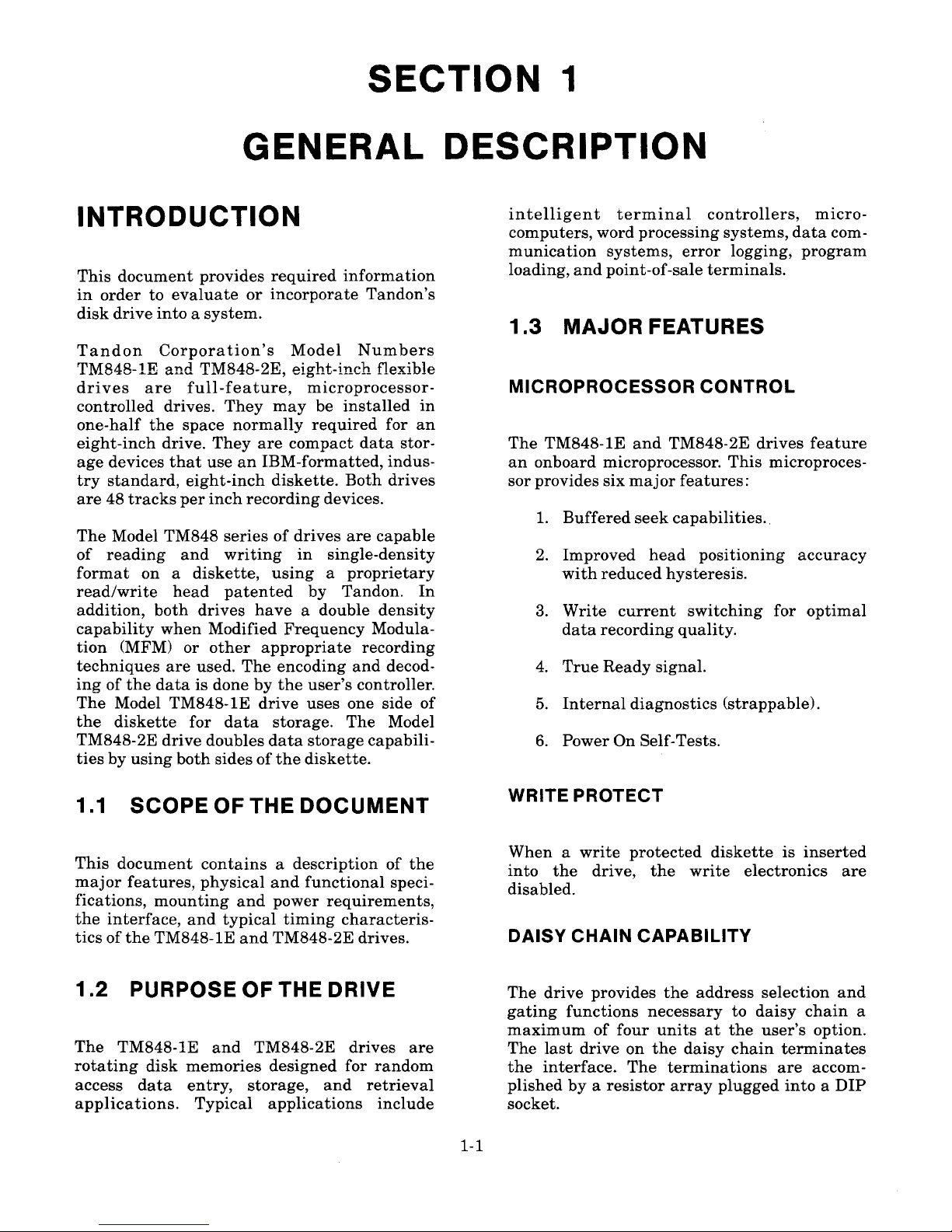
A representative drive is shown in Figure 1-1.
The drive can be mounted in a vertical or hori-
zontal plane. However, the logic circuit board
must be on the uppermost side when the drive
is mounted horizontally.
The drive conducts a power on self-test as part
of the normal power on sequence. Two of the
tests do not require a diskette to be inserted.
These tests are: the head carriage stepping in,
away from, Track 0, and the head carriage
stepping out toward Track 0. Failure of either
of these tests is indicated on the front panel
L.E.D. by the following flashing sequence:
3 flashes, then 2: Fails to s t ep in fr o m
Track 0 or Tr a c k 0
sensor is always equal
to zero.
The spindle is rotated by a direct drive, brush-
less D. C. motor with an integral tachometer.
The crystal-controlled serv o c i r cuit and
tachometer control the speed of the spindle.
Operator access for diskette loading is pro-
vided via a horizontal slot located at the front
of the drive.
3 flashes, then 3: Fails to st e p out t o
Track 0 or Tr ack 0
sensor is always equal
to one.
The read/write double-head assembly is posi-
tioned by a split band positioner mounted to a
microprocessor-controlled stepper motor. The
read/write heads are glass-bonded, ferrite/
ceramic structures with a lif e expectancy of
15,000 operating hours.
A third test monitors the index sensors when-
ever the diskette lever is closed, and must
have a diskette inserted into the drive. If the
diskette lever is closed without a diskette in
place, or the spindle motor fails to operate, an
error message flashes on the front panel
L.E.D. in the following sequence:
3 flashes, then 4: No index pu l se wit h
The control electronics of the driv e ar e
mounted on a printed circuit board located
above the chassis. Power and interface signals
are routed t hr ough co nn ectors pl ugging
directly into the logic circuit board. A second
circuit board, mounted under the drive, oper-
ates the brushless D. C. spindle motor.lever closed.
1-3
Page 9
~>GURp y.y
OISK Qp]yp
Page 10

SECTION 2
PRODUCT SPECIFICATIONS
INTRODUCTION
This section contains the mechanical, electrical, reliability, and environmental specifications for the
TM848-1E and TM848-2E drives.
2.1 MECHANICAL SPECIFICATIONS
Figure 2-1 contains the physical dimensions of the drive.
2.2 ELECTRICAL AND OPERATIONAL SPECIFICATIONS
The electrical and operational specifications are located in Table 2-1.
2.3 RELIABILITY SPECIFICATIONS
The reliability specifications are located in Table 2-2.
2.4 ENVIRONMENTAL SPECIFICATIONS
The environmental specifications are located in Table 2-3.
1 7 9049-001
REY. A
CRVI C I E3 f l COR ORA ON,CH TSWORTII,CAL O • IA 9 1
2-1
Page 11

6-32 THD
THRU 4 PLCS
(2 EACH SIDE)
Q5)
Go
O0
1 2.00
' (304.8 MM)
/ 0.149 DIA TOP X
0.156 DIA BOTTOM
X 0.430 DEEP
4 PLCS
8.00
(203.2 MM)
o o
o o
o)
• Oo
3.50
(88.9 MM)
0 o
p
L~o
/
1.20
(30.5 MM)
0.75~ '
(19.0 MM)
1.60
(40.6 MM)
(25.4 MM)
7. 50
(190.5 MM)
1.650
(41.5 MM)
0.52
(13.2 MM)
8.550
(217.2 MM)
2.025
(51.4 MM)
2.300
(58.4 MM)
NOTES: 1. DIMENSIONS ARE GIVEN IN INCHES. METRIC EQUIVALENTS ARE IN PARENTHESES.
2. TOLERANCE ON ALL DIMENSIONS IS
H-.020 INCH.
3. WEIGHT IS APPROXIMATELY 5.7 POUNDS.
FIGURE 2-1
DISK DRIVE OUTLINE DRAWING
1 79049-001
REV. A
mn d n n DDRPDRATIDN, DHATswDR H, DALIPDRNIA 31311
2-2
Page 12

TABLE 2-1
ELECTRICAL AND OP ER AT IONA L SP ECIF I CAT ION S
Media
6
203.20 millimeter, 8-inch IBM industry
standard diskette
3 x 10 passes per track
48 TPI, both drives
Media Life (for reference only)
Tracks Per Inch
Tracks Per Drive
TM848-1E
TM848-2E
Track Spacing
Inside Track Radius
Both Drives, Side 0
TM848-2E, Side 1
Outside Track Radius
77 tracks per drive
154 tracks per drive, 77 per side
0.529 millimeter, 20.8 milinches
51.50 millimeters, 2.03 inches
49.42 millimeters, 1.95 inches
Both Drives
TM848-2E, Side 1
91.75 millimeters, 3.61 inches
89.64 millimeters, 3.53 inches
15,000 media contact hours
Head Life
Disk Rotational Speed,
microprocessor controlled
Instantaneous Speed Variation (ISVl
Motor Start Time
Seek Time, Track to Track
Head Settling Time
Average Track Access Time
including head settling time
Data Transfer Rate
360 RPM ~ 1.5 percent
1 percent
150 milliseconds, maximum
3 milliseconds, minimum
15 milliseconds
91 milliseconds
500,000 bits per second
1 79049-001
REV. A
an d n n DDRPDR ATIDN, DHATswDRTH, DALIFDR • IA 91311
Page 13

TABLE 2-1 (CONTINUED)
ELECTRICAL AND OP ER AT IONAL SP ECIFICATIONS
Flux Reversals Per Inch (FRPI),
inside track
Both Drives, Side 0
TM848-2E, Side 1
Unformatted Recording Capacity
6,536 FRPI
6,816 FRPI
TM848-1E 0.8 megabyte per disk
1.6 megabytes per diskTM848-2E
D. C. Voltage and Current
Requirements
+ 24 volts D. C. Power + 24 volts, ~ 10 percent at 700
milliamperes, typical. For surge current
requirements, see Figures 2-2 and 2-3.
+5 volts, ~ 5 percent at 450
milliamperes, typical
+ 5 volts D. C. Power
Typical Current Requirements
For +24 volts D. C.
Spindle Motor
Stepper Motor
Electronics
Power Dissipation
Shipment
170 milliamperes
400 milliam peres
130 milliamperes
20 watts, typical
When prepared for shipment by Tandon,
the drive meets the requirements of
NSTA preshipment test procedure
Project 1A.
179049-001
REV. A
KRV I d C ln OO RPO R ATIO • .OHATSTIIORT • CALIFORNIA R 3
2-4
Page 14

Configured for stepper motor enabled during motor start, 2.25 amps typical surge.
C 2 5
U
R
R
E
1.5
1.O
T
0.5
N o
I
50 100 150
TiME IN MiLLISECONDS
200
250
A p
S
FIGURE 2-2
+24 VOLT D. C. CURRENT, CONFIGURATION 1
Configured for stepper motor disabled until motor comes up to speed, 1.8 amps typical surge.
STEPPER MOTOR
ENABLED
C
2.5
U
R
2.0
1.5
E
N
10
T
0.5
I
N
50 100
A
150
TIME IN MILLISECONDS
200 250
M p
S
FIGURE 2-3
+24 VOLT D. C. CURRENT, CONFIGURATION 2
1 79049-001
REY. A
an d a n cDRPDRATIDN,c • ATswDRT •,cALIFDR • IA 91311
2-5
Page 15

TABLE 2-2
RELIABILITY SPECIFICATIONS
Error Rates, maximum, exclusive
of external sources, e.g.:
electronics, defective and
contaminated diskettes
Soft Errors (Recoverable)
Hard Errors (Nonrecoverable)
Seek Errors
6
One in 10 bits
One in 10 bits
One in 10 seeks
10,000 power-on hours
30 minutes
Mean Time Between Failures
Mean Time To Repair
TABLE 2-3
ENVIRONMENTAL SPECIFICATIONS
Temperature
4.4 C to46 C,40 F to 115 F
— 40 C to 71 C, — 40 F to 160 F
Operating, media dependent
Nonoperating
Relative Humidity
Operating, noncondensing,
media dependent
Nonoperating, noncondensing
20-to-80 percent
5-to-95 percent
1 79049-001
REV. A
CR n d E 3 & CORPO RATION, CHATSWORTH. CALIFORNIA 91311
2-6
Page 16

SECTION 3
OPERATION
INTRODUCTION 3. Remove the cardboard shipping insert,
and retain for future shipment.
4. Ensure that the front panel is secure.
5. Ensure that the circuit board is secure.
6. Ensure that the connectors are firmly
This section contains information on how to
unpack, check out, install, and operate the
TM848-1E and TM848-2E drives.
seated.
3.1 UNPACKING THE DRIVE
3.3 MOUNTING THE DRIVEThe drives are packaged in protective con-
tainers to minimize the possibility of damage
during shipment. The following list is the
recommended procedure for unpacking the
drive.
CHECKOUT
3.2 PREINSTALLATION
Before applying power to the drive, the follow-
ing inspection should be conducted:
4. Check the contents of the container
against the packing slip.
5. Investigate the contents of the con-
tainer for possible damage.
6. Notify the carrier immediately if any
damage is found.
surface.
2. Remove the upper half of the container.
3. Remove the drive from the lower half
of the container.
1. Place the container on a fla t work
The drive has been designed so it m ay b e
mounted in any plane, i.e.: upright, horizontal,
or vertical. When mounted horizontally, the
Logic circuit board side of the chassis must be
the top side.
Eight holes are provided for mounting: two on
each side and four on the bottom of the hous-
ing (see Figure 2-1). The two mounting holes
on each side are tapped for 8-32 screws. The
four mounting holes on the bottom require
8-32 thread forming screws. When installed in
either plane, horizontal or vertical, only two
mounting screws are required to securely hold
the drive in place.
Optional straps are available to permit two
drives to be attached together for installation
in standard width drive openings.
Any mounting scheme in which the drive is
part of the structural integrity of the enclo-
sure is not per m itted, M ounting schemes
should allow for adjustable brackets or incor-
porate resilient members to accommodate
tolerances. In addition, it i s recommended
that mounting schemes include no more than
two mounting surfaces.
The drive is manufactured and tested with
some critical internal alignments that must
be maintained. Hence, it is important that the
mounting hardware not introduce significant
stress on the chassis.
1. Check to ensure that the diskette lever
opens and closes.
2. When the lever is moved to an open
position, the head arm raises.
3-1
Page 17

DUST COVER All int erface signals are TT L compatible.
Logic true (low) is +0.4 volt maximum. Logic
false (high) is +2.4 volts minimum.
The design of an enclosure should incorporate
a means to prevent contamination from loose
items, e.g., dust, lint, and paper chad since the
drive does not have a dust cover.
INPUT CONTROL LINES
COOLING
These input lines are individually terminated
through a 150 ohm resistor pack installed in
the dip socket located at integrated circuit
location RP5 (or RP1 in the Large Scale Inte-
gration version). In a single-drive system, this
resistor pack should be installed to provide
the proper terminations. In a multi ple-drive
system, only the last drive on the interface is
to be terminated. All other drives on the inter-
face must have the resistor pack removed.
The drive can terminate the following input
lines:
Heat dissipation from a single drive is nor-
mally 20 watts, 68 BTU per hour, under high
load conditions. When the drive is mounted so
the components have access to a free flow of
air, normal convection cooling allows opera-
tion within the specified temperature range.
When the drive is mounted i n a confined
environment, air flow must be provided to
maintain specified air te mperatures in t h e
vicinity of the motors, printed circuit hoards,
and diskettes.
When forced air is u sed, air flow m u st be
directed outward from the drive. Do not
intake ai r through the drive
nr heads a nd
diskettes.
1. Direction
2. Step
3. Write Data
4. Write Gate
5. In Use
6. Side Select (TM848-2E only)
7. Write Current Switch
8. Head Load
3.4 INTERFACE CONNECTIONS
MOTOR ON CONTROL
Interface connections for the TM848-1E and
TM848-2E are made via a user-supplied, fifty-
pin, flat ribbon connector, 3M Scotchflex, Part
Number 3415, or its equivalent. This connec-
tor mates directly wit h the ci rcuit board
connector at the rear of the drive.
The interface description of the connectors,
and the location of each one, is contained in
this section. Interface lines are located in
Table 3-1. D. C. power connector pin assign-
ments are located in Table 3-2, Section 3.5 of
this manual.
The signal wire harness should be of the flat
ribbon or twisted pair type, have a maximum
length of ten feet, and have a 26-to-28 gauge
conductor compatible with the connector to be
used. It is recommended that the interface
cable have a characteristic impedance of 100
ohms.
DRIVE SELECT LINES
The Motor On Control lines are used to control
the spindle motor. With the MOL jumper in
(factory installed), the Motor On Control lines
are low true. With the MOH jumper installed
(optional), the Motor On Control lines are
high true (see Table 3-3 located in Section 3.6).
The Drive Select lines provide a means of
selecting and deselecting a drive. These four
lines, DS1 through DS4, allow independent
selection of up to four drives attached to the
controller.
When the signal logic level is true (low), the
drive electronics are activated, and the drive
is conditioned to respond to Step or to Read/
3-2
Page 18

TABLE 3-1
DRIVE INTERFAC E LINES AN D P IN ASSIG NM E N T S
Ground Pin Signal
11
13
15
17
19
21
23
25
27
29
31
33
35
37
39
l 1
43
45
47
49
1
3 5 7
9
10
12
14
16
18
20
22
24
26
28
30
32
34
36
38
40
l A
'+8
44
46
48
50
2
4
6 8
Write Current Switch
Motor On Control 1
Motor On Control 2
True Ready, (Motor On Control 3, Optional)
Two Sided (Strappable) (TM848-2E only)
Disk Change (Strappable)
Side Select (TM848-2E only)
In Use Indicator (Strappable)
Head Load Line/Motor Control
Index
Ready
Motor On Control 4
Drive Select 1 (Side Select Option, TM848-2E only)
Drive Select 2 (Side Select Option, TM848-2E only)
Drive Select 3 (Side Select Option, TM848-2E only)
Drive Select 4 (Side Select Option, TM848-2E only)
Direction Select (Side Select Option, TM848-2E only)
Step
Write Data
Write Gate
Track v
Write Protect
Read Data
Alternate I/O
Alternate I/O
Write commands. When the signal logic level
is false (high), the input control lines and the
output status lines are disabled,
The Drive Select address is determined by a
select shunt on the circuit board. Drive Select
lines 1 through 4 provide a means of daisy
chaining a maximum of four drives to a con-
troller. Only one can be true (low) at a time.
An undefined operation might result if two or
more drives are assigned the same address or
if two or more Drive Select lines are in the
true (low) st ate s i multaneously. A Dri ve
Select line must remain stable in th e tr ue
(low) state until an y operation in progress
(Step, Read/Write) is completed.
Using Side Select options 18 thr ough 48 ,
Drive Select lines may be used as Side Select
lines for the TM848-2E (see Section 3.6).
DIRECTION SELECT AND STEP LINES
(TWO LINES)
When the drive is selected, a true (low) pulse
on the Step line, with a time duration greater
than one microsecond, initiates the access
motion. The direction of motion is determined
by the logic state of the Direction Select line
when a step pulse is issued. The motion is
toward the center of the disk if the Direction
Select line is in the true (low) state. The direc-
tion of motion is away from the center of the
disk if the Direction Select line is in the false
(high) state.
To ensure proper positioning, the D irection
Select line should be stable at least 1 micro-
second. prior to the corresponding rising edge
of the step pulse, and remain stable 100 nano-
seconds after it.
3-3
Page 19

NOTE
patterns and adjust the Write Data w ave-
form. Although a value cannot be specified for
write precompensation, Tandon suggests a
value of 125 nanoseconds for systems using
MFM double density recording format.
TM848-1E and T M 848-2E
drives include a microprocessor-
controlled buffered seek capa-
bility. The controller may issue
step pulses of one microsecond
minimum width, and fifteen
microseconds minimum spacing
between trailing edges. Internal
drive electronics issue step com-
mands at a rate of three
milliseconds.
WRITE GATE
The drive electronics ignore step pulses when
one of five conditions exists:
When this signal i s true (l o w), the write
electronics are prepared for writing data and
the read electronics are disabled. This signal
turns on Write Current in the selected Read/
Write head. Data is written under the control
of the Composite Write Data and Side Select
input lines. When the Write Gate line is false
(high), all write electronics are disabled.
When a write protected diskette is installed in
a drive, the write electronics are disabled, irre-
spective of the state of the Write Gate or Side
Select lines. With the NP jumper installed, a
diskette cannot be write protected.
1. The Write Gate is true (low).
2. The Direction Select is false (high),
and the head is positioned at Track 0.
3. The drive is not selected.
4. When trying to seek beyond Track 76.
5. When the diskette lever is opened.
NOTE
Changes of state of the Wri te
Gate line should occur before
the first Write Data pulse.COMPOSITE WRITE DATA
IN USE
When the drive is selected, this interface line
provides the bit serial Composite Write Data
pulses that control the switching of the Write
Current in the selected head. The write elec-
tronics must be conditioned for writing by the
Write Enable line.
For each high-to-low transition on the Compos-
ite Write Data line, a flux change is produced
at the writ e head gap. This causes a flux
change to be recorded on the media.
When a double-frequency type encoding tech-
nique is used in which data and clock form the
combined Write D ata signal, it is recom-
mended that the repetition of the high-to-low
transitions, while writing all zeros, be equal to
the nominal data rate, ~0.1 percent, and the
repetition of the high-to-low transitions, while
writing all ones, be equal to twice the nominal
data rate, ~ 0.1 percent.
Host controllers may implement write precom-
pensation circuits that recognize worst case
SIDE SELECT
WRITE CURRENT SWITCH
This strappable feature controls the lever lock
solenoid when the DL option is installed.
Normally, Write Current switching is accom-
plished by the host controller. A true (low)
level on this line reduces the Write Current.
Using option IC, t he dr i v e au t omatically
reduces Write Current at Track 43.
The Side Select interface line, available only
on Tandon's TM848-2E, defines which side of
a two-sided diskette is used for reading or
writing. An open circuit, false (high) level
3-4
Page 20

WRITE P ROTECT
selects the Read/Write head on side zero, the
lower head of the drive. A true (low) level on
this line selects the Read/Write head on side
one, the upper head of the drive. When switch-
ing from one head to the other, a 100 micro-
second delay is required before any Read or
Write operation can be initiated.
The Write Protect signal is provided to indi-
cate to the user that a write protected diskette
is installed. This signal is true (low) when the
diskette's Write Protect notch is uncovered.
When the Write Protect signal is false (high),
the write electronics are enabled, and write
operations can be performed.
HEAD LOAD LINE/MOTOR CONTROL
READ DATAThis line may be used to control the spindle
motor and/or the l ever lock s olenoid (see
Section 3.6).
OUTPUT CONTROL LINES
The Read Data line transmits data to the con-
troller when the drive is selected and not
writing. It provides a pulse for each flux tran-
sition recorded and detected on the diskette by
the drive electronics. Normally, this signal is
false (high). It becomes true (low) for th e
active state. The Read Data output line goes
true (low) for a duration of 200 nanoseconds,
~ 50 nanoseconds, for each change recorded
on the diskette.
There are eight output lines, five of which are
standard and three of which are strappable
features. The standard output signals are:
Index/Sector, Track 0, W r ite Protect, Read
Data, and Ready. The strappable output sig-
nals are Disk Change, Two-Sided, and True
Ready.
READY
INDEX
The Ready interface signal indicates a disk-
ette has been inserted into the drive. Ready
will not return to th e false state until th e
lever is opened, and is not affected by Spindle
Motor Control.
When a si n gle-sided diskette is installed,
Ready is active (low) if side zero is selected.
Ready is false (high) if side one is selected on
the TM848-1E. When a two-sided diskette is
installed, Ready is active when either side of
the diskette is selected on the TM848-2E.
The Index signal represents the output of the
Index sensor. An Index pulse is provided once
every revolution, 166.67 milliseconds nominal,
to indicate the beginning of a t r ack t o the
controller. The leading edge of thi s si gnal
must a l w ays be used to ensure tim ing
accuracy. The Index line remains in the true
(low) state for the duration of the Index pulse,
which is nominally four milliseconds.
TRACK 0
TRUE READY
When the drive is selected, the Track 0 inter-
face signal indicates to the controller that the
Read/Write head is positioned on Track 0, the
outermost track. Thi s signal remains true
(low) until th e R ead/Write head is m o ved
away from Track 0. This signal is false (high)
when the selected drive's Read/Write head is
not on Track 0.
The True Ready interface signal indicates the
diskette is rotating at 360 RPM and a seek
operation is complete, i.e., the head has
settled. This may be used to indicate seek com-
plete when using the buffered seek operation.
3-5
Page 21

TYPICAL INTERFACE
CHARACTERISTICS
NOTE
This is a stra ppable feature
with the Motor Control 3 input
signal line.
Lines between the controller and the drive
have the following characteristics:
V, True
=
+ 0.4 volt maximum at I
DISK CHANGE
This strappable feature provides a true (lowl
signal to the interface when Drive Select is
activated if the drive has gone from a Ready
to a Not Ready condition while deselected.
This line is reset on the true-to-false transition
of Drive Select if the drive has gone to a
Ready condition.
=
48 milliamperes, maximum
V, Fal se
=
+ 2.4 volts minimum open
microamperes, maximum
collector at I,
=
250
Figure 3-1 contains the electrical interface
characteristics. Figure 3-2 contains the control
and data timing reauirements.
3.5 D. C. POWER
TWO-SIDED
This op tion i s ava ilable o nly on M odel
TM848-2E. True (low) indicates that a two-
sided diskette is installed.
D. C. power is supplied to the drive through a
six-pin AMP connector, J2, mounted on the
circuit board. T h e mat ing c o nnector, not
+5V
150 OHMS
?4LS14 OR
EQUIVALENT
+ TRUE
+ TRUE
TRANSMISSION
LINE ~
7438 OR
LEQUIVALENT
10 FEET
DRIVER I RECEIVER
FIGURE 3-1
ELECTRICAL INTERFACE CHARACTERISTICS
3-6
Page 22

D. C. POWER
90 MILLISECONDS MINIMUM
VALID CONTROL
OUTPUT SIGNALS
$
500 NIINOSECO NDS MAXIMUM
DRIVE SELECT
SIDE SELECT
(TM848-2E ONLY)
100 MICROSECONDS MAXIMUM
I
DIRECTION
SELECT
1 MICROSECO N D
MINIMUM
1 MICROSECOND
MINIMUM
13 MILLISECOND
1 MICROSECOND MINIMUM
1 MICROSECOND MINIMUM
STEP
15 MICROSECONDS MINIMUM
90 MILLISECONDS
MINIMUM
18 MILLISECONDS
TRUE READY
WRITE GATE
100 MICROSECONDS
MINIMUM
9n sg
II I I
S E
A
AN APENS
I MINIMUM
I
SEE NOTE 4 MICROSECO NDS MAXIMUM
I
WRITE DATA
16 MILLISECONDS MINIMUM
50 MICROSECONDS
MINIMUM
VALID READ DATA
SIG NAL
SEE NOTE
90 MILLISECONDS MAXIMUM
NOTE: 150 MILLISECONDS, MINIMUM, DELAY MUST BE INTRODUCED AFTER DRIVE SELECT TO ALLOW TIME FOR THE D. C.
MOTOR TO REACH 360 RPM OR THE OPTIONAL TRUE READY LINE MUST BE MONITORED.
FIGURE 3-2
CON TRO L AND DATA TIMING REQUIREME NT S
3-7
Page 23

supplied, is AMP Part N u mber 1 -480270-0,
using AMP contact Part Number 606191-1.
Pin assignments are found in Table 3-2.
The chassis should be connected to ea rth
ground to ensure proper operation.
time. Drive Select is implemented by shorting
one of the four connections, using a shorting
plug. The drive comes equipped from the fac-
tory with DS1 installed. All outputs are gated
with drive select, as set-up at the factory.
TABLE 3-2
DS1 DS2 DS3 DS4 DRIVE SELECT
X
Pin
D. C. POWER CONNECTOR
PIN ASSIGNMENTS
Supply Voltage
+24 volts D. C.
24 volts Return
5 volts Return
+5 volts D. C.
Return
X
Selects Drive 0 via
J1-26.
Selects Drive 1 via
J1-28.
Selects Drive 2 via
J1-30.
Selects Drive 3 via
J1-32.
X
HEAD SELECT OPTIONS
(S1 — S3 and 1 B — 4B)
3.6 DRIVE ADDRESS AND
OPTION STRAPPING
The Side Select options allow the user to select
the heads by various means. They are imple-
mented by removing the shorting plug from
the DS1 — DS4 option pads.
The drive address and option strapping is
determined by the different jumper configura-
tions required for s pecific system applica-
tions. If jumper configurations are changed,
power should be cycled off and on so the micro-
processor can recognize the new configuration.
The description o f user-selectable options
should be used in conjunction with Table 3-3.
Throughout Section 3.6, an X denotes jumper
installation, and a dash de n otes jumper
removed.
HEAD SELECT USING DRIVE SELECT
DRIVE SELECT (DS1 — DS4)
To use the Drive Select lines to select the
heads, etch cut S2 and install S3 along with
one of the 1B — 4B jumpers. The 1B — 4B con-
trol signal selected may not be the same con-
trol line used for Drive Select, or an undefined
condition results. When the control line that
corresponds to th e Drive S elect jumper is
driven low (true), the drive is enabled, and the
lower head, Head 0, is selected. When the con-
trol line that c o rresponds to t h e 1 B — 4B
jumper is d riven low (tr ue), the dr ive is
enabled, and th e up per head, Head 1, i s
selected.
This option allows the user to daisy chain up
to four drives, and to enable one drive at a
3-8
Page 24

TABLE 3-3
OPTION PATCHING
As Shipped
Trace
Designator Installed
Not
InstalledOption
Drive Select
Head Select
Head Select Using Drive Select
Power Save
Stepper Power From Head Load Line
Spindle Motor Control
Motor Control Signal, Low True
Motor Control Signal, High True
Motor Control Select
Ready
True Ready
Lever Lock Solenoid
In Use, Lever Lock Option
In Use, Latched
In Use, Not Latched
Disk Change
Two-Sided Diskette Installed
Inhibit Write When Write Protected
Allow Write When Write Protected
External Write Current Switch
Internal Write Current Switch
Diagnostic Mode
DL
D
LL
NL
DC
2S
NP
XC
IC
DM
DS1 — DS4
S1 — S3
1B — 4B
PS
HL
Ml, M3, M4
MOL
MOH
MC1 — MC4
X
X
X
X
DS1
S2
M1, M3
X
X
X
X
X
DS2 — DS4
S1, S3
X
X
X
3-9
Page 25

HEAD SELECT USING DIRECTION SELECT
During a Read or Write operation, the state of the Direction Select line is undefined. Hence, it may be
used to select the desired head. A high enables Head 0. A low enables Head 1. To incorporate this
option, etch cut S2 and install Sl.
S1 S2
X
S3 1B 2B 3B 4B
X X
X X
X
X
HEAD SELECT
Head Select via J1-14.
Head Select via J1-26.
Head Select via J1-28.
Head Select via J1-30.
Head Select via J1-32.
Head Select via J1-34.X
STEPPER MOTOR POWER
(PS, PS*, DS, HL)
turn off delay of the spindle motor is activated
on the trailing edge of the M o tor Control
signal.
With Motor Control using Drive Select or
Head Load, the M3 and M4 jumpers determine
which method of Motor Control is enabled. If
option M3 or M4 j u mpers are installed, the
Motor On Control, MC1 — MC4, options operate
in a l o gical OR manner w ith the co ntrol
signal(s) selected by the M3 and M4 jumpers.
When the PS j u mper is installed, stepper
motor power is controlled by the Drive Select
line, DS, or the H ead Load line, HL. When
either line is true (low), the stepper motor is
driven with full power, and is ready for a Seek,
Read, or Write operation. When either line is
false (high), +5 volt stand-by current is sup-
plied to the stepper motor to hold the head car-
riage assembly in position. When the P S*
option is in, the stepper motor continuously
receives full power. PS* is diametrically oppo-
site PS (see Figures 3-3 and 3-4).
NOTE
If the Motor Delay Timer option
(M1) is inst all ed, t h e f iv e
second turn off delay is in effect
regardless of which M3/M4 con-
figuration is implemented.
X
-
X
X
X
- -
X
SPINDLE MOTOR CONTROL OPTIONS
(M1, M3, M4, MOL, MOH, MG1 — MG4)
PS PS~ DS HL STE PPER POWER
Stepper Power
continuously on.
Stepper Power on with
Drive Select.
Stepper Power on with
Head Load line J1-18.
X
X X
X
M1 M3 M4 MOTO R CONTROL
Enables five-second
motor off delay timer.
Motor Control only
with MC1 — M4 options.
Motor Control using
Drive Select.
Motor Control using
Head Load.
Motor Control using
Drive Select and Head
Load, logical AND.
Ml is used to enable the motor off delay timer.
When this jumper is installed, a five second
3-10
Page 26

MOL MOH MC1 MC2
X
MC3 MC4
X X
X X
MOTOR CONTROL
Motor Control signals are low
(true) active.
Motor Control signals are high
(true) active.
Motor Control selected via J1-4.
Motor Control selected via J1-6.
Motor Control selected via J1-8.
Motor Control selected via J1-24.
X
OONL
U7
OOMOH
4S Ooo DS4
3S OOO DS3
2S Ooo DS2
I S oOO DS I
Oo R
Oo D
Oo S3
OO S2
Oo S I
Oo DC
Oo 2S
Oo TR
Oo MC4
Oo MC3
Oo MC2
Oo MC I
Oo IC
Oo XC
OO
OOHL
OODM
OODL
Oo M4
OOM3
OOMI
O PS
rg
I
pe PS+
FIGURE 3-3
LSI CIRCUIT BOARD ASSEMBLY
3-11
Page 27

4 B 000 DS4
3 B 000 D S 3
2 B 000 D S2
I B 000 DS I
0 MOH
0
UID
0 MDL
OLL
0
ONL
M 100 UI 3
M300
M4 00
DL 00
DM op
HL OO
0 PS
tpl
LOJ PS +
OWP
0
ONP
FIGURE 3-4
NON-LSI CIRCUIT BOARD ASSEMBLY
00 R
00 D
00 S3
00 S 2
00 S I
00 D C
00 2S
00 T R
00 MC4
00 MC3
00 MC2
00 MC I
00 I C
00 XC
3-12
Page 28

READY AND TRUE READY (R AND TR)
When the R j umper is installed, the Ready
signal is available at the interface. When the
TR jumper is installed, the True Ready signal
is available at the interface.
The R j u mper i s standard, while t he TR
jumper is optional. These two lines are inde-
pendent functions, and may be used separately
or together.
R TR READY OR TRUE READY
X
-
Ready signal via J1-22.
DISK CHANGE (DC)
This output is used to i ndicate to the con-
troller that a disk change has been made. The
internal signal i s gated with Driv e Select.
When the lever is opened, the Disk Change
line goes low (true), and remains low until the
trailing edge of the next Drive Select.
DC DISK CHANGE
Disk Change signal not available.
Disk Change signal available via
J1-12.
TWO-SIDED DISKETTE INSTALLED (2S)X True Ready signal via J1-8.
When using th e Tru e Ready
option, Motor Control 3 may not
be used.
NOTE
When a tw o-sided diskette i s installed,
internal circuitry gates this signal with Drive
Select. It sends a lo w (true) signal to th e
controller, indicating t h a t a doubl e-sided
diskette i s insta lled (index hol e t wo is
present). This option is factory installed.
2S TW O - SIDED DISKETTE
LEVER LOCK OPTIONS (D, DL, LL, NL)
Two sided diskette si
rr
na1 n
nt
available.
Two-sided diskette signal available
via J1-10.
The lever lock solenoid, an optional feature,
can be controlled by the In Use interface line
X X X
X X
-
X Lat ched by In Use
J1-16.
D DL LL NL LEVER LOCK
SOLENOID
Latched with Drive
Select.
via J1-16, true (low).
Active energizes
solenoid.
Latched by In Use
via J1-16. Active low,
in conjunction with
Drive Select, latches
the solenoid. The
solenoid remains
latched until In Use
is false (high) on the
leading edge of Drive
Select.
WRITE PROTECT (WP AND NP)
This WP option is used to lock out the Write
Gate when a write protected diskette i s
installed. It is factory installed.
The NP option allows the controller to write
on any diskette, whether or not it is w r i t e
protected. It does not stop the Write Protect
signal from being sent on the interface line.
This option is implemented by removing WP,
and installing NP.
WP NP
X
WRITE PROTECT
Disables Write Protect, for
write protected diskette.
Allows writing on any
diskette.
X
3-13
Page 29

WRITE CURRENT SWITCH (XC AND IC) 3. Reinstall the jumpers in their original
configuration.
4. Power on the drive.
The XC option allows the host controller to
switch the Write Current independently of the
drive's onboard microprocessor. It is factory
installed.
To implement the IC option, remove the XC
jumper, then install a jumper at IC.
XC IC
3.7 DISKETTES
X
X
DIAGNOSTIC MODE OF OPERATION
(DM, DL, M1, M3, M4)
WRITE CURRENT
SWITCHING
External Write Current
switch.
Microprocessor automat-
ically switches Write Cur-
rent at Track 43.
The TM848-1E and TM848-2E drives use an
IBM-compatible, eight-inch diskette. D isk-
ettes are available with a single index hole or
with multiple (index and sector) holes.
Diskettes with a single hole are used when
soft sector format is required. Multiple hole
diskettes provide sector information through
the use of an index sensor and electronics.
Figure 3-5 illustrates the diskette used with
the drive. This recording media is a flexible
diskette enclosed in a protective jacket. The
diskette, free to rotate within the j acket, is
continuously cleaned by its soft fabric lining
during normal operation.
The test programs allow the user to test some
aspects of drive operation without the use of
special test equipment. The programs allow
the user to isolate the problems of the drive.
The diagnostic mode provides 16 tests (see
Table 3-4).
To enter the diagnostic mode:
1. Make a note of whic h j u m pers are
installed for normal operating condi-
tions (see Table 3-3).
2. Remove the D L, M 1, M 3, an d M 4
jumpers.
3. Install the D M j ump er, and supply
power to the drive.
4. Using the DL, M l , M3, and M4
jumpers, select the diagnostic test
desired by inserting the jumper accord-
ing to Table 3-4.
LOADING THE DISKETTE
The drive is loaded by inserting the diskette,
with its head aperture forward, into the front
slot of the drive. Access to the diskette loading
slot is obtained by opening the front lever.
The diskette should be carefully inserted until
it is solidly against the back stop.
CA UTION
Damage to the center o f the disk-
ette may result if the door is
closed when the diskette is not
properly inserted. This prevents
reliable recovery of the recorded
data.
WRITE PROTECT TAB
To exit the diagnostic mode:
1. Remove power from the drive.
2. Remove the DM, DL, M1, M3, and M4
jumpers.
The drive is equipped with a Writ e Protect
Sensor Assembly. This sensor operates in con-
junction with the diskette, which has a slot
cut in the protective jacket.
3-14
Page 30

TABLE 3-4
DIAGNOSTIC MODE OF OPERATION
DL M4 M3 Ml Test Description of Test
Seek to Track 0, and turn on spindle motor. This test
seeks the carriage to Track 0, and turns on the spindle
motor. It may be used to check the Track 0 status.
Seek to Track 1, and turn on spindle motor. This test
seeks the carriage to Track 1, and turns on the spindle
motor. It may be used for index-to-data burst testing
with an alignment diskette.
Seek to Track 38 from Track 0, and turn on spindle
motor. This test seeks the carriage to Track 0, then to
Track 38. It may be used for radial alignment adjust-
ment with an alignment diskette.
Seek to Track 38 from Track 76, and turn on spindle
motor. This test seeks the carriage to Track 76, then to
Track 38. This test, along with the previous one, is used
to measure hysteresis.
Seek to Track 76, and turn on spindle motor. This test
seeks the carriage to Track 76, and turns on the spindle
motor. This test may be used to check index-to-data
burst and azimuth.
Seek to Track 75, and turn on spindle motor. This test
seeks the carriage to Track 75, and turns on the spindle
X
X
X
motor.
Toggle front panel L.E.D. with each revolution of the disk.
This test toggles the front panel L.E.D. at the leading
edge of each side zero index pulse. A single-sided disk
should be used for this test.
Toggle front panel L.E.D. with each revolution of the disk.
This test toggles the front panel L.E.D. at the leading
edge of each side one index pulse. A double-sided disk
should be used for this test.
Alternate seek between Track 0 and Track 76 with spindle
motor on. This test continuously moves the carriage
between Tracks 0 and 76. This test is used to exercise
the positioner system.
Seek to Track 2, and monitor the Track 0 sensor. This
test moves the carriage to Track 2, and displays the
state of the Track 0 sensor. The Track 0 sensor sho"ld
change state at Track 2.
X
3-15
Page 31

TABLE 3-4 (CONTINUED)
DIAGNOSTIC MODE OF OPERATION
DL M4 M3 Ml Test Description of Test
10/A
X
X
X X
14/E
13/D
11/B
12/C
Monitor the write protect sensor. This test checks the
write protect sensor. The front panel L.E.D. should turn
on and off by moving a disk, which has the write protect
notch covered, in and out of the drive. The L.E.D. is on
when write protect is true.
Alternate seek between Track 0 and Track 4 with spindle
motor on. This test is used in conjunction with a scope to
d~namicall~ test the Track 0 sensor.
Monitor the status of the lever position switch. This test
is used to check the lever position switch. The front
panel L.E.D. flashes on and off with the opening and
closing of the diskette lever position switch.
Alternate seek between Track 74 and Track 76 with spin-
dle motor on. By writing data on Track 75, this test
determines if the head movement over that track causes
any erasure. A time of 30 milliseconds is allowed for the
head to settle at the end of each seek.
Turn spindle motor off. This test turns off the spindleX
motor.
Flash version number. This test outputs the firmware
version number to the front panel L.E.D.
15/F
Notes: X
=
Jumper In
-
=
Open
3-16
Page 32

S.O INCH
SEALED
PROTECTIVE
JACKET
INDEX HOLE
OXIDE COATED
MYLAR DISK
SPINDLE
ACCESS HOLE
LINER
HEAD
APERTURE
WRITE PROTECT NOTCH
FIGURE 3-5
RECORDING MEDIA
DISKETTE HANDLING AND STORAGE
When the slot is covered with an optically
opaque, self-adhesive tab, the diskette is write
enabled. When the tab is removed, the diskette
is write protected.
and to enhance the service life of the diskette,
the following handling procedure should be
observed.
1. Return the diskette to the protective
jacket when not in use.
2. Avoid exposing the d i skette to an y
magnetizing force in excess of 50
oersted.It is important the diskette be handled and
stored correctly so the integrity of the recorded
data is maintained. A damaged or contami-
nated diskette can impair or prevent recovery
of data, and can r esult i n dam age to the
Read/Write heads.
Figure 3-5 contains an i llustration of the
physical configuration of th e d i skette. The
7.88-inch diskette is ox ide-coated, flexible
mylar. It is enclosed in an eight-inch square
protective jacket. In addition, openings for the
drive hub and diskette index hole are provided,
Figure 3-6 provides some helpful hints on the
care and handling of the drive and diskettes,
In addition, to ensure trouble-free operation
NOTE
The 50-oersted level magnetiz-
ing force is reached approxi-
mately t h ree in ches f rom a
typical source, e.g., motors, gen-
erators, or transformers.
3. To avoid warping the diskette, do not
store it in direct sunlight,
4. Do not use a lead pencil or a ballpoint
pen to write on the label. Use a felt
tipped pen, and mark lightly on the
label.
3-17
Page 33

DO NOT TOU C H P R EC I-
SION SURFACE WITH
YOUR FINGERS.
TO AVOID DA MAG E TO
THE DISKETTE AND TO
YOUR DRIVE, INSERT
DISKETTE CAREFULLY
UNTIL THE BACKSTOP
IS ENCOUNTERED.
RETURN THE DISKETTE
TO ITS JACKET WHEN
NOT IN USE.
DO NOT WRITE ON THE
JACKET WITH PEN OR
PENCIL. USE A FELT
TIPPED PEN.
KEEP THE D ISKETTE
AWAY F R O M M A G -
NETIC FIELDS.
DISKETTES SH OULD
BE STORED AT
HANDLE WITH CARE;
BENDING AND FOLD-
ING MA Y D A M A G E
DISKETTE.
10'C to 52'C
50 F to125'F
FIGURE 3-6
DISKETTE CARE AND HANDLING
Page 34

a n o n
CORPORATE OFFICES
20320 PRAIRIE STREET
CHATSWORTH, CA 91311
TELEPHONE NO.: (213) 993-6644
TELEX NO.: 194794
TWX NO.: 910-494-1721
P/N 179049.001A (T5007A 5-83)
PRINTED IN U.S.A.
 Loading...