


1\
~'
'anaon
"
'-
"
'"'--.
'-
.".,'''.
'-'"
TAN
DON MAGNETICS CORPORATION
9333
OSO
AVENUE
CHATSWORTH, CALIFORNIA 91311
(213) 993-6644
TM
100
DISK DRIVE
OPERATING & SERVICE MANUAL
023-6017

TABLE
OF
CONTENTS
PROPRIETARY NOTICE
Information contained in this document
MAGNETICS CORPORATION and may
or in part
by
any
person without prior written approval of TANDON
MAGNETICS CORPORATION. Itisprovided asanaidtothe
with no guarantee, written
with regard
to
©copyright
any specification.
1979
or
implied, that the documentisaccurate
TANDONMAGNETICS CORPORATION
is
copyrightbyTANOON
not
be duplicated in full
usef
SECTION
Introduction Purpose of Equipment
Description Diskettes Mechanical
Uncrating
Mounting
Protect
SECTION
Introduction
GENERAL DESCRIPTION
I
tbe
Disk Drive Physical Checkout
the
Disk Drive·. . . Diskette Handling and Storage . . . Loading
...
DC
Power Requirements.
II
THEORYOFOPERATION. . . . . . . . . . . . . . . . . . . . . . . . .
...
Organization
olthe
Disk Drive
AND
SPECIFICATIONS. . . . . . . . . . . .
...
Physical Description of Equipment
and
Electrical Specifications
...
Interface Connections
...
Functional Block Diagram Description
...
Write Protect . . . Track00Switch . . . Spindle Drive . . . Positioner Control
SECTION
Figure
Figure 2
Figure 3
Figure 4
Figure 5
Figure 6
Figure 7
Figure 8
Figure 9
Figure 10
Figure
Figure
Figure 13
Figur.'4
Figure 15
III
Introduction
Board Test Points
..•
1
TM
Recording Medium. . . . . . . . . . . . . . . . . . . . . . . . . . . . . . . . . . . . . . . 0
Outline TM100 Disk Drive. . . . . . . 0 • 0 • • • 0 • • • • • • • • • • • • • • • • • • 0 • •
Diskette
Diskette Access . . . • • . . . . . 0 • • • 0 0 • • • • • • • • • • • • • • • • • • • • • • • • • • 0 7
Write Protect
TM100
FM .Aecording . 0 • • • • • • • • • • • • • • • • • • • • • • • • 0
Write Timing Diagram 0 • • • • • • • • • • • • • • 0 • • • • • • • • • • • • • • • • • • • • • • • 12
Read Timing
11
logic
12
Servo P.C.B.A
Interface Configuration. . .
Catseye Pattern. . . . . . . 0 • 0 • • 0 • • 0 • • • • 0 • • • • • • • • • • 0 • • 0 • • • • • • • • •
IndextoData . 0
OPERATION
Physical Description of PCBA's
...
Option Select
100
Disk Drive : . . . . . . . . . . . . . . . . . . . . . . . . . . . . . . . . . . . . . .
eare
FunctionatBlock
.........................•...............
...
...
Adjustment
liST
OF
ILLUSTRATIONS
and
Handling . . . . . . . . . . . . . . . . . . . . . . . . . . . . . . . . . .
Tab
. . . . . . . . . . . . 0 • • • • • • • • • • • • • •
Diagram 0
Interface Electronics Specifications
•••••••••••••••••••
Diagram 0 • • • • • • • • • • • • • • • • • • • • • • • 0 0 • • • • • 13
PoC.B.A
.•..
0
••••••••••
••••••••••••••••••••••••••••••••••••••••
.'.
. . . . . . . 0 • • • • • • • • • • • • • • • • • • • • • • • • 0 •
0
••••••••••••••••••
0
••••••••••••
...
Interface Specifications .
...
the
...
Functional
Chassis Ground .
Diskette . . . Write
...
Index
Data Electronics
...
••
•••••••••••
•••
• 0 • • • • • • • • • • • • •
0••0••0
0 • 0
0
•••••
••••••••
•••••
..
..
...
Circuit
..
••
••
..
0 8
0
1
9
14
1
3
5
6
10
11
14
15
15
20
21
LIST
OF
TABLES
Table - Mechanical
Table - Interface Connector Pin Assignments,
and
Electrical Specifications. . . 0 0 • • • 0 • • • • • • • • • • • 0 • • • 0 • 0 •o.4
Jl/P1
Table - Power Connector Pin Assignment 0
0
••••••
••••••••••••••••••
0
•••••••
0 0
•••••
16
0
••
16

SECTION I
GENERAL DESCRIPTION AND SPECIFICATIONS
1.1 INTRODUCTION
This section provides
TANDON MAGNETICS CORPORATION.
1.2
PURPOSEOFTHE DRIVE
The
TM100
retrieval applications. These applications typically are intelligent terminal controllers, micro-computers.
processing systems,
terminals.
The
TM100iscapableofrecording
1.3
PHYSICAL DESCRIPTIONOFTHE DRIVE
The
TM100
when
however,
The
spindleisbelt
and
pulleys,
positionedbymeansofa
The
read/write/erase
20,000
hours.
Operator
access
The
electronic
the
chassis,
connectors
the
which
the
physical
Disk Driveisa
data
communications
Disk Driveisshown
mounted
horizontally,
drivenbyademotor
the
tachometer
for
componentsofthe
other
plug
control
stepper
head
assemblyisa glass-bonded ferrite/ceramic
diskette
loading is provided via a slot
(servo) is
directly
and
functional specifications for
"MINI"
Disk Memory designed for
systems.
and
reading digital
in Figure 1.
motor,
Drive are
mountedatthe
into
the
The
the
printed
with an integral tachometer.
the
speedofthe
split
band,
mountedontwo
rearofthe
logic PCBA.
the
random
error
logging, micro-program loading.
data
usingFM,
Drives
canbemountedinany
circuit logic
spindle.
and
a suitablv sized
locatedatthe
unit.
MFM,orM2FM
board
mustbeuppermost.
The
The
read/write double-sided
structure
PCDA's,
Power
and
TM100
Disk Drive.
access
verticalorhorizontal plane;
servo
control
puney.
which has a fife in excess
frontofthe
oneofwhich Hogic)islocated above
interfacesignals are
manufactured
data
entry,
storage,
and
pointofsale
techniques.
circuit, suitably sized
head
assembly
unit.
routed
and
word
through
by
is
of
TM
100 DISK
Fig. 1
DRIVE

(,f"-"'-'~
1.4
The Disk Drive.isfuttyself-contained
Drive consists of a spindle drive system, a head positioning system, and read/write/erase system.
When the front latch
place by plastic guides, and the front latch. Inlout location
back stopisencountered.
Closing the front latch activates the conelclamp system resulting in centeringofthe
the diskettetothe drive hub. The drive
motor. In operation, the magnetic headisloaded intocontact with the recordingmedium whenever the front
latch
is
The magnetic headispositioned over·the desired track by meansofa4-phase stepper motor/ba,nd assembly
and
its associated electronics. This positioner employsa one-step
When a write-protected
electronics of the Drive andanappropriate signal is appliedtothe interface.
When performing a
then tunnel erasedto0,30
Data recovery electronics include a low-level read amplifier, differentiator, zero-crossing detector,
digitizing circuits.
No
data decoding facilities are provided in the basic Drive.
The Drive
1.5
TheTM100
or
hole
Diskettes with a single hole are used when secto.rinformationisprerecorded on the diskette. Multiple hole
diskettes provide sector informationbymeans of the index sensor
Figure 2 is a simpUfied drawingofthe
medium
the jacket,
1.6
MECHANICAL·AND ELECTRICAL SPECIFICATIONS
The mechanical
1.7
INTERFACE
Levels: True
The interface circuits are designed so
1.8
UNCRATING THE DISK DRIVE
The Disk Drive is shipped
damage during shipment. The
Drive.
(1) Place the containerona flat work surface.
(2) Remove the outer cardboard sleeve from around the Inner container.
(3) Remove theupper half
(4) Remove the Disk Drivefrom the lower halfofthe inner container.
(5) Check thecontentsofthe
\
FUNCTIOhl"\L DESCRIPTIONOFTHE
is
opened, accessisprovided for the insertionofa diskette. The disketteispositioned in
closed.
disketteisinserted into
write operation, a 0,33
mOl
(0.012 inch) Cnominal).
is
also supplied with
(1)
A Track 00 switch which senses when the Head/Carriage assembly
(2)
The index sensor, which consistsofan
that when
resolution device which can distinguish holes placed close together, i.e., Index-Sector holes in a
hard sectored diskette.
(3) The write-protect sensor disable
to
DISKETTES
multiple holes.
is
a flexible magnetic disk enclosed in a protective Jacket. The protected disk, free to
False
possible.damage; notify the carrier immediatelyIfany damageIsnoted.
an
index hole is detected, a digital signal is guaranteed. The index sensor usedisa high
the disketteCsee section
uses a standard
is
continuously cleaned by
and
electrical specifications for the
SPECifiCATIONS
II:
+O.4v(maximum)
= +2.4v (minimum)
the.
.1.
133.4mm
that
ina
protective container which, whenbulk packaged, minimizes the possibility
follOWing
of
the
shippingcontainer against the packing
DRIVE
and
requires'no operator intervention during normal operation. The
is
ensured·when the disketteisinserted until a
diskette
hubisdrivenata constant speedof300
the
mOl
(0.013-inch) (nominal)
following sensor systems:
LED'Ught source
the
Disk Drive electronics whenever a write-protect
16 and figure 6).
(5.25
inch) diskette. These diskettesare available with a single Index
diskette used with the Disk Drive. It
th,
soft fabric liningofthe Jacket during normal operation.
Disk~rive
a disconnected wire results in a false signal.
procedure describes
inner-container.
rotationtocause a 1-treck Unear' movement.
Ddve, the write;;protect senior disables
andphototransistor,
andelectronicl.
are given in Table 1.
thetecommended
rpmbya servo controlled dc
data
track is recorded. This ,track
is
canbesaenthat
method
sUp.
Investigate
and
positionedatTrack
is positioned such
tabisapplied
this recording
rotate
for uncfatlng
the
contents
clamping
the
within
the
write
and
.,.
Disk
for
6.30I0,25
3fi6mm
ul'40
of
--J~~
'NCIIl .
.,
11
..
-lI
1015I0.0'
mm
'NCIII
T
i
'33,4
10m
(5?5
E~
(0
is
e-
\1)(;
dO
+1·
~~
I!:?
INC'"
L
::.~;
,'::...
:;.~:
:~~H'
LINER
of
1.9
PHYSICAL CHECKOUT
Before applying powertothe unit, the following inspection shouldbeperformed:
(1)
Front'atch.
head arm raises.
(2) Ensure
(3) Manually rotate the drive hub. The
(4) Check
(5) Check for debris
Check that the
that
the front panelissecure.
that
PCBA's are secure. Check that the connectors are firmly seated.
or
foreign material between the heads and remove same.
RECORDING MEDIUM
Fig. 2
front
latch opens
hub
should rotate freely.
..1
•I
and
closes. Note that when the doorisopened, the
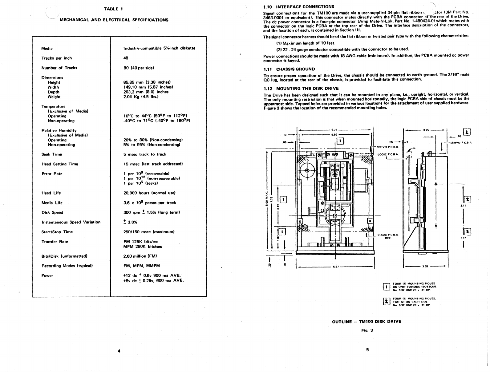
TABLE 1
MECHANICAL AND ELECTRICAL SPECIFICATIONS
Media
Tracks per inch
Number of Tracks
Dimensions
Height
Width
Depth
Weight
Temperature
(Exclusive
Operating
Non-operating
Relative Humidity
(Exclusive
Operating
Non-operating
Seek Time
Head Setting Time
Error Rate
Head
Media
Disk Speed
Instantaneous Speed Variation
Start/Stop
Transfer
Bits/Disk (unformatted)
Recording Modes (typicaU
Power +12
life
life
Time
Rate
of
of
Media)
Media)
Industrv-compatible 5%-inch diskette
48
80
85,85mm(3.38 inches)
149,10mm(5.87 inchest
203,2
2.04
100eto44°C
-40°Cto7,oe
20%to80% (Non-condensing)
5%
5 msec track
15 msec (last track addressed)
20,000
3.6x10⁶passes Per track
300
~
250/150
FM
MFM
2.00
FM,MFM,MMfM
+5v dc
(40
per
side)
mm
(8.0) inches
Kg
(4.5 IbsJ
(GOoFto112°F)
(-400F
to
95% (Non-condensing)
to
track
per
109(recoverable)
10'2(non-recoverable)
per
106(seeks)
per
hOUfS
(normal use'
rpm:!: 1.5% (long term)
3.0%
msec (maximum)
125K bits/sec
250K bits/sec
million (FM)
de~O.6v
±0.25v,
900
ma AVE.
600maAV
to
16ooF)
E.
1.10
INTERFACE CONNECTIONS
Signal connections for
3463-0001
The dc power connector
the
and
The
Power connections
connector
1.11 CHASSIS GROUND
To
ac lug, 'Clcated
1.12 MOUNTING THE DISK DRIVE
The
The only mounting restriction
uppermost side. Tapped holes
Figure 3 shows
or
connectoronthe
the
locationofeach,Iscontained in Section
signal connectorharnessshouldbeof the flat ribbonortwisted pair type with the following characteristics:
(1)M~ximum
(2)
22 -24gauge
lskeyed.
ensure proPer
Drive has
13__'"
.06
.-...,
the
equiva'end.
operationofthe
at
been
the
~-.....-
i
TM100 are made via a user·supplied 34-pin flat ribbon\.,
This connector mates directly with
is
a four-pin connector (Amp Mate-N-Lok, Part No. 1,.480424-0) which mates with
logic PCBAatthe
length
of10
conductor
shou'dbemade wit,h18 AWGcable (minimum).Inaddition,
the
rearofthe
designed such
locationofthe
I
is
.feprovidedin
top
rearofthe
",.
feet.
compatible with
Drive,
chassis,
that
it canbemounted
that
when
recommended mounting holes.
5,75
5.50
.m
the
the
chassis shouldbeconnectedtoearth
'sprovided
mounted
horizontally,
various loc:;ations for
thePCBA
Drive.
The
connectortobe
·to
facilitate this connection.
in any plane, i.e., upright, horizontal, or vertical.
•
'itor
connector anile rear of
interface description of the connectors,
used.
the
PCBA
ground. The 3116" male
the
logic
peBA
the
attachmentofuser supplied hardware.
sideofchassis must be the
(3M
mounteddcpower
+-t-t·
~
1
m
I
~
,..;
I
lOGIC
lLD
CIO
~jJL---II'
It
gill
"'IF'
UUII
" • I
REF.
PC8.A
.--,
.~
~
• 5,81 •
OJ
r;l
~
L-3~-1
FOUR. ,•. t
MOUNTING
,.ONUNIT
No,
6·32
UNe18" .31
FOUR '4t. MOUNTING. HOLES.
TWO
f2t ON
No,
6·32
tJNe28" .31
HOLES
FARStOEC80lTOMt.
EACH
SlOE
OP
OP
Part No.
the
Drive.
fiJ
3.12
I
,~
Hn
I
OUTLINE
4
- TM100 DISK
Fig. 3
5
DRIVE

1.12.1 HARDWA.
The Disk Driveismanufactured with certain critical internal alignments that mustbemaintained. Therefore,
it
is
important
Any mounting scheme
Mounting schemes should allow for adjustable brackets or incorporate resilient members
tolerances.
Mounting schemes involving more than three mounting points should
that
the mounting hardware does not introduce significant stressonthe Drive.
in
which the Driveispart of the structural .intergrity of the enclosureisnot
be
avoided.
permitted.
to
accommodate
1.12.2OUST COVER
Since the Disk Driveisnot provided with a dust cover, the design ofanenclosure should incorporate a means
to
prevent contamination from loose items, e.g., dust, lint, paper chad, etc.
1.12.3COOLING
Heat dissipation from a single Disk Driveisnormally15watts (51 Btu/Hr) under
the
Drivels mounted so
allowsoperation over the specified temperature range.
When the Driveismounted in a confined environment, air flow must be providedtomalntain specified air
temperatures in
1.12.40RIVE
In additiontothe cooling requirements specified in Paragraph 1.12.3, a minimum separationof26,4mm
(1
inch) between· Drivesisrecommended. Thisisrequiredtoavoid electrical interference between the motors
of one
at
least 1,52 mm (O.060-inch) thickisplaced between units. However, useofthis steel sheet may increase the
cooling requirements.
SEPARATION
Drive and the magnetic head of another Drive. Closer mountingisallowableIfa gounded sheetofsteel
1.13 DISKETTE
It
·is
important
maintained. A damaged
damage
to
the read/write heads.
that
the components have accesstothe free flow
the
vicinity of the motors, PCBA's,
HANDLING
that
the diskettebehandled
AND
STORAGE
or
contaminated diskette can impairorprevent recoveryofdata
and
and
stored properly so
diskette.
that
hi",Uneconditions.
ofafr,normal
the integrityofthe recorded
convection cooting
and can result in
When
data
Figure 2 illustrates the physical configuration of the diskette. The diskette is an oxide coated, flexible mylar
disk, 130,2
protective jacket. Read/write/erase head access
drive
Figure 4 provides some helpful
to
handling should
mm
(6.125
inches) in diameter, andisenclosed in
hub
and
diskette index hole are also provided.
assure trouble-free operation and enhance the service life of the diskette, the following procedures for
be
observed:
hi~lts
on the care and handlingofthe
is
made through an aperture in the jacket. Openings for the
an
133,4
mm x
133,4
Disk Drive and diskettes. Additionally,
/
mm(5.25x
5.25-inch)
Return the diskettetothe protective jacket when not in use.
Avoid exposing the diskettetoany mangetizing force in excess of50oersted.
NOTE
The50oersted levelofmagnetizing forceisreached
of
approxilnately76mm
motors,
generators, transformers.
Do not
stare
the diskette in direct sunlight as warping could resutt.
Do
not
use a lead pencit or ballpoint pentowrite on the label.
on
the label.
1.14
LOADING
Diskette. loadingisaccomplished by inserting the properly oriented diskette. into the front slot provided.
Access
tathe
THE DISKETTE
diskette loading
slotisobtained by opening the front latch. See Figure 5.
(3 inches)
from
at
a typical source, e.g.,
a distance
Use
a felt tip
pen
and mark IightiV
The diskette should· be carefully inserted untit the diskette jacketissolidly against the backstop.
CAUTION
DAMAGE
RESULT
NOT
is
RECOVERY OF THE RECORDED DATA.
TO THE CENTER HOLE
IF
THE DOOR IS CLOSED WHEN THE IJISKETTE IS
PROPERLY INSERTED. THIS WILL PREVENT
IN
THE DISKETTEMAY
RELIABLE
00
NOT TOUCH PRECISION SURFACE
WITH YOUR FINGERS
FIEt-OS.
Wlnt
CARE BENDING
MAY
AWAV
.
FROM
DAMAGE
KEE'
DISKETTE
MAGNEnC
UANOLE
AND FOLDING
DISkETTE
DISKETTE CARE
TO AVOID DAMAGE TO THE DISKETTE
AND TO YOUR DRIVE, INSERT
CAREFUllY
ENCOUNTERED
RETURN
lUE
WHEN NOT
OISKETllS
,00
10
5l'1C
Q
to"
10
I2S
AND
HANDLING
Fig. 4
UNTtl
BACKSTOP IS
OISKETtEfOITS
I.N
USE
SltOULOBESTORED
f
OI$KUTE
JACKel
At
"'"
"""''-
",-
'\.'.".
DISKETTE
Fig. 5
ACCESS

1.15 WRITE
The Disk Driveisequipped with a write
diskette having a slot
When the slot
to
writeonthe
t,~",eCT
cut
in the protective jacket.
is
covered with a self-adhesive tab,
diskettE!. Figure 6 illustrates
WRln
PROffcr
TAO
~
@
o
O·
,-
1.16
DC
POWER REQUIREMENTS
+12:!:O.6vdc:
+6 :!:O.25v de:
900MA
600
MA
(MAX
(MAX
protect
switch assembly. This sensor operates in conjunction with a
The
location of the slotisshown in Figure 6.
the
disketteiswrite protected. The slot must be uncovered
howtoinstan a
fOlO
OVER
OACI<
Fig. 6
<lOOmv
-I!--'-
P.P. ripple
-------11
INDEX ACCESS HOLE
WRITE PROTECT TAB
AVE.)
AVE'),
tabtocover
the
slot.
OJ
@.
-~
o
Of
Ol<;t<fl
f[
I--
356
mrn
";t4
'NCH'
6.30
r
IO'~
INCH,
Tf
96.5
mm
"~lNC"'
....",..
TAO
",,,n
SECTION
II
THEORY OF OPERATION
2.1
INTRODUCTION
This section provides a
TM100 Disk Drive.
The
Disk Drive consists of
ana
diskette.DCpower
ba.sic
description of
the
mechanical
at
+12 v and + 5v (provided
and
the
operationofthe TANOON MAGNETICS CORPORATION
electrical
components
by
the
necessarytorecord and read digital data
user)isrequired for operation.
2.2 ORGANIZATION OF THE DISK DRIVE
All
electrical subassemblies in the Disk Drive are constructed with leads which terminate in 4 or 5 pin
connectors. enabling the individual.assemblies
The magnetic heads are connected
associated male sockets which are localed in close
Interface signals
signals are presented in Section
and
power are provided via connectorsatthe
to
til
of this manual.
to
be removed.
the
PCBA via cables terminated in 5-pin female connectors and its
proxi.mityto
the
read/write
rear of the Drive. Detailed description of these
data
electronics.
2.3 FUNCTIONAL BLOCK DIAGRAM DESCRIPTION
Figure 7isfunctional block diagramofthe
the
following discu$sion:
The
identificationofthe elementsofthis discussion
associated figures are related
only
representedinsimplified
The Disk Drive
con$ists of
the
following functional groups:
TM
100
Disk Drive
NOTE
to
the actual schematic
forminthis section.
and
$hould be referredtoin conjunctionwith
and
the
and
are
* Index Pulse Shaper
* Write Protect Sensor
* Track 00 Sensor
• Spindle Drive Control
* Carriage Position Control
• Write/Erase Control
and
• Read Amplifier
2.5 INDEX
An index pulse is providedtothe
consists of an Index LED, Index
disk passes
Transistor causing it
Network which produces a pulse for each hole detected. This pulse
PULSE Interface tine.
2.6
A Write Protect signalisprovidedtothe user system via the WRITE PROTECT interface tine. The write
protect
When a write
write
2.1
The level
the
and
2.8 SPINDLE DRIVE
The Spindle Drive system consists of a spindle assembly drivenbya
through a drive belt.
Associated with the spindle drive
The control circuitry also includes a current limiter
ENABLE interface line
drive
the
Index LED/Photo Transistor combination, light from
to
WRITE PROTECT
circuitry consists of a Write Protect Sensor
protected
~Iectronics
TRACK"
head.ispositionedatTrack0.and
senttothe
motor
and
supplies the status signaltothe
SWITCH
on
the TRACK00interface lineisa function of
user.
exceeds
1.3
Digitizer
user system via
Photo
Transistor,
conduct.
The
signal from
disf<etteisinserted in
the
motor
is
true,
the
drive
ampere,
motorisallowedtocomeupto
the
current limit circuitry disables
the
INDEX PULSE interface line. The index circuitry
and
a Pulse Shaping Network.Asthe index hole in
the
Index
Photo
Transistorispassedtothe Pulse Shaping
is
and
circuitry'toroute
the
drive,
the
sensorisactivated and
interface.
the
stepper
motorisat
are
the
servo electronics required for control.
and
position of the magnetic head assembly. When
the home position, a true levelisgenerated
an interface control line. When the DRIVE MOTOR
the
the
LED strikes the Index Photo
presentedtothe
the
dcmotor-tachometer
speed. When
motor
drive.
useronthe
signal produced.
the
the
current through the
INDEX
logic disables the
combination
the
8
9

DC
STEPPER MOTOR
INlHtfACE
CONTUOl
<4.._-_._--
IND[)(
PlltSf-
WHITE
"Honel
.-----'
TM
100
FUNCTIONAL BLOCK DIAGRAM
Fig. 7
2.9
POSITIONER CONTROL
The Head Positioning system utilizes a four-phase stepper
track advancement
provided as an element for inhibiting positioner
2.10
DATA
Information can be recordedonthe diskette using a double-frequency code. Figure 8 illustrates the
magnetization prQfiles in each bit cell for the number sequence shown.
The erase gaps provide
tolerances in track positioning.
All
signals requiredtocontrol the data electronics are providedbVthe user system and are shown in
diagram, Figure
of
the Read/Writecarriage. In additiontothe logic necessary for motion
motion
ELECTRONICS
an
erased guard bandoneither side of the recorded track..·T
7. These control signals are:
motor
drive
w"ichchanges
during a write operation.
one
phase for each
contro',
a gate
....isaccommodat«!s
the
block
• SELECT
• WRITE.ENABLE
DATA
SIDESELECT
The READ
• WRITE
*
DATA
composite signalissenttothe user system via the interface.
the
-H
BIT
CEll~_
I 1 I 1
BITPATT£RN
NWRITEOATA
MAGNETIZATION • 1
,i
MAGNETIC
El~MENTS
I • I
I I I
I I I
I ! I
>(
Y'
)"'
>f Y .
I
I
1-
I I
I •
I •
7)(
/ :
If
¥
....
G·;:.f
II
'i
F M RECORDING
Fig. 8
2.10.1
DATA
RECORDING
ReferringtoFigure 7, it
Write Waveform Generator, Erase Current Source, Trim Erase Control Logic,
The read/write winding
Write Current Source flow in alternate halves of the winding under control of the Write Waveform Generator.
Before recordinr can begin, certain conditions must be satisfied. The conditions required for recording
O.e.,
unit ready must be establishedbVthe
CH
Drlvespeed stabilization. This condition will exist
(2) Subsequent
total after the last step pulseisinitiated, i.e., 5 msec for the step motion and 15 msec for settling.
is
Figure 9 shows the relevant timing diagram for a write operation. At t
ENABLE interface line goes true, this enables the Write Current Source.
the
Since
the WAITE ENABLE interface line.Itshouldbenoted
at
Figure
Generator which togglesonthe leading edge of every WAITE
Note that a minimumof4 usee end a maximum
WRITE
At
I"
last significant WRITE
The TRIM ERASE signa' must remain true for
thataUrecorded
.I
and
The
TRIM ERASE. This
trim erase gaps are behind the read/write gap, the TRIM ERASE control goes true
Track0.and Track 34 so
9 shows the information
DATA
pulseisonly requirediffaithful reproduction
the
endofrecording,atleast
34.
durationofa write operationisfrom
c~n
be seen
that
the Write Electronics consist of a Write/Erase Current Source and
on
the magnetic headiscenter-tapped. During a write operation, current from the
us,er
system as follows:
250
msec after starting the drive motor.
to
any step operation, the positioner must be allowedtosettle. This requires
NOTE
Allofthe foregoing operations can be overlapped,ifrequired.
that
that
the effectofthe trim erase gapsonprevious informati.onisminimized.
on
the WRITE
DATA
of8
one
DATA
data
are trim erased.·This valueisagain optimized between the requirementsatTracks
Is
indicated by the internal WRITE BUSY waveform shown.
additional pulseonthe WRITE
pu'setoavoid excessive peak shift effects.
800
the
true-going edgeofWRITE ENABLEtothe false-going edge of
this valueisoptimited between the requirements
interface line,
DATA
usecbetween WRITE ENABLE going true
olthe
usec after the termination of WRITE ENABLEtoensure
::::
0 when the
and
the
pulse.
first WRITE
DATA
a'1d
Head Select Logic.
unit
is
readv, the
output
of theWrite Waveform
DATA
transitionissignificant
line must be inserted after the
390
and
20msec
WR
ITE
usee after
the first
0.

WAITE ENABLE
'RIM
ERASE
INTERNAL
WAllE
BUSY
NWAITEOATA
WAITE
WAVEFORM
GENERATOR
WRITE
CURRENT
,~0
NOTE 1
f NOTE 1
,
I
390
~
sees~'
I
I I 1 1 I
'J-;
I I
It·
I I I
I I I
I I 1
1i--f~1
I
,--L
r-"J
~
800
users
s--r
S.
I t
S~
~
I
r-:--t
t I
-..J
I
~
I
LINEAR OUTPUT FROM
OUTPUT FROM DIFFERENTIATOR
READ DATA INTERFACE
FitTER
NOTES: t = 0 =250 MILLISECONDS AFTER DRIVE MOTOR STARTS,
t
t =0
OR
20
MILLISECONDS AFTER STEP COMMAND,
100
u SECONDS AFTER TERMINATION OF WRITE
BUSY, (WHICHEVER
IS
THE LATEST TIME)
OR
NOTES
2.10.2
DATA REPRODUCTION
The Read Electronicsconsist of
I~0
~250
M'LLISECONOS
STAATSOR2OMIlliSECONOS
PULSE,
4WH'CHEVER'STHE
WRITE TIMING DIAGRAM
the
following:
AFTER
OAIVE
AFTER
LATEST TIME)
Fig. 9
MOlOA
LAST STEP
UNSYNCHRON'ZEO
8.5
MI\
PEAKTOPEAK
.. u
SECONOS
M'NIMUM,
8 "
S£CONOS
* Read Switch/Side Select
* Read Amplifier
* Filter
* Differentia tor
* Comparator
The Read Switch
during a write operation. The side select
Before reading
ready condition must
Paragraph 2.10.1 a
Read Amplifiertosettle after
Referring
filteredtoremove noisebya linear phase Filter. The linear outpUt from
Differentiator which generates 8 waveform whose zero crossovers correspondtothe peaksofthe
signal. This
The Comparator
the
interface line.
to
signatisthen fedtothe
read signal. This Composite Read Data signal is
and
Digitizer
is
usedtoisolate the Read Amplifier from
can
begin,
the
Drive mustbein a ready condition. As
be
established by the user system. In additiontothe
100
usee delay must exist from
the
Figure 10,
the
output
and
Digitizer circuitry generates a 1usee READ
is
usedtoenable
transient caused by the Read Switch returningtothe
signal from.
Comparator
the
voltage excursion across the magnetic head
oneofthe
the
trailing edge of
the
read/write headisamplified
and
Digitizer circuit.
then
read/write/erase heads.
with
DATA
senttothe
the
data
recording operation, this
requirernents established in
the
TAIMERASEsignattoallow
pulse correspondingtoeach
user system via
Read
mode.
bya
read amplifier
the
Filterispassedtothe
the
READ DATA
MAXIMUM
peak
READ TIMING DIAGRAM
Fig. 10
the
and
read
of
l'

SECTION
III
OPERATION
3.1 INTRODUCTION
This section
TM100 Disk Drive. Also presented are schematic diagrams of
3.2
The
servo
illustrate
J3
READ/WRITE
HEAD
contains
the
interface description
PHYSICAL DESCRIPTIONOFTHE PCBA's
logic PCBAisapproximately
PCBA
is
approximately 127mm(6.0 inches) long
the
placementoftest
~~
:>%
CONNECTORS'RM
P5
0:
WQ
~~
..1%
P6
146
points
mm
(5.75 inches) tong by
and
connectors.
and
the
mechanical/electrical adjustments necessary for
by38mm
TP2 •
o
TPI •
TPI,
•
C48~~~)(i~
%Zzzz25!.
PROGRAMMABLE
SHUNT
SOCKET
HE.
Jl
,NTERfACE
CONNECTiON CONNECTIONS
/
.TP5
1Pl.
.UNUSEO
I}O
INTERfACE
TPH
1P9
I
II·
••
P6
,.p,o.
~~
%..
~
a
t
..
~y
~~~Y-CONNECTOR
~'..
TERMINATOR I n 0 0 0 I
SOCKET'2F1
ii
LOGIC P.C.B.A.
Fig.
11
the
PCB
• TP8
TN
. - . -
~o
~
:~
!
A's installed in
146
mm
(1.5 inches) wide. Figures
TP4 •
TP10
TP3 •
the
(6.75 inches) wide,
•
o
AI
T~13
/
%SERYO
p"mpl3
','-
:
~
c(
~
~
.•.
I
" .
..•.--.
:1
,
-',
Disk Drive.
11
STEPPER
MOTOR
J2.
J4
POWfR
the
and'
the
and
12
~ER'
o
o
R4 SPINDLE
SPEED CONTROL
3.3
INTERFACE ELECTRONICS SPECIFICATIONS
All
Interface signals are
(minimum). Figure 13 illustrates
It
Is
recommended
«>hans
Cor
equivalent twisted pairs).
Interface
connector
3.3.1 INPUT CONTROL LINES (SeeTable
3.3.1.1 SELECT LINES (NDS1-NDS4)
The
SELECT lines provide a meansofselecting
standard) select
(low).
the
commands. When
A SELECT line
command
The
daisy-chaining a maximumoffour
An undefined operation might result if two.
SELECT
Disk Drive electronics are activated
is completed.
Disk Drive addressisdeterminedbya Select
lines
areinthe
+
TRUE
TTL
compatible. Logic
that
pin
oneofthe
the
must
the
the
interface cablebeflat ribbon cable, with a characteristic impedanceof100
assignments
four Disk Drives
logic level is falseChigh).
remain stable in
true
Clow)
r
--------1
I
'""
I
I
I
I . I
L
'~6
~~E~:V~~~
interface configuration. Maximum interfacecable length is10feet.
and
power
the
Disk Drivestoa controller. Only
state
simultaneously.
'"
~
+'
DRIVER
INTERFACE CONFIGURATION
SERVO JUMPER
DRIVE MOTOR
SERVO P.C.B.A.
Fig.
12
true·
(low) is +0.4v (maximum), logic false (high) is +2.4v
connector
pin
assignments are given in Table 2
2.
and
deselecting a Disk Drive. These four lines (NDSO-NDS3
attachedtothe
and
the
the
input
true
Clow)
Shuntonthe
or
more
TWISTED
I
TRANSMISStON
Fig.
controller. When
Driveisconditionedtorespondtosteporread/write
control
lines
state
until
the
PCBA. SELECT lines 0-3 provide a means
.LINE
t
I
I
I
I
I
t
I
I
REeEtVER
I
I
I
I
one
.5V
units
~,
10
are assigned
PAIR
FEET
the
signal logic levelistrue
and
output
status tines are disabled.
executionofa steporread/write
line
canbetrue
the
same addressorif
150
OHMS
14lS04OREOU.VAlENT
13
and
Table 3.
(low)ata time.
twoormore
•
TRUE
of

INTERFACE CONNECTOR PIN ASSIGNMENTS.
Ground
1
3
5 6
9
11
13 14
15
17
19
21
23
31
-
-
Ground
7
25
27
29
33
TABLE 2
Controller-to-Disk Drive
Signa'
2
4
10
12
16
18
20
22
24
32
Disk Drive-to- Controller
Signal
8
26
28
30
34
POWER CONN,ECTOR PIN ASSIGNMENT
Pin
1
2
3
4
Description
Connector
(Spare)
SELECT 3 (NOS3)
SELECT 0 (NDSO)
SELECT 1 (NDS1)
SELECT 2 (NDS2)
DRIVE-MOTOR ENABLE (NMOTORON)
DIRECTION
STEP (NSTEP)
WRITE DATA (NWRITEDATA)
WRITE GATE (NWRITEGATE)
SIDE SELECT (NSIOE SELECT)
Description (Mnemonic)
INDEX (NINDEX/SECTOR)
TRACK
WRITE PROTECT (NWRITEPROTECT)
READ
Connector
TABLE 3
Supply Voltage
+12v
Return(+12v
Return
+5v
de
00
DATA
de
C+5v
(Mnemonic)
clamp
(NTRK00J
Clamp
det
J1/P1
(NREADDATAJ
de)
3.3.1.2
When
and
stop
3.3.1.3
Whe'n
Hne
line
true
the
the
STEP pulse
initiatedonthe
DRIVE MOTOR ENABLE (NMOTORON) ,
this signal line logic leve' goes
stabilizes in 'ess
DIRECTION
the
Disk Driveisselected, a
initiates
when
a STEP pulse is issued.
(low)
state
DIRECTION
DIRECTION line
and
than
and
the
access
motion.
when
a STEP pulse is issued.
line
isinthefa1se
shouldbestable 0.1 usec
remain
stable
trailing edgeofthe
250
true
msec. When
STEP Lines(2Lines)
true
(low) pulse
The
directionofmotionisdeterminedbythe
The
motion
(highl
until
0.1 usee
STEP pulse.
3.3.1.4 WRITE DATA (NWRITEDATA)
When
the
the
WRITE ENABLE line (see Paragraph 3.3.1.5).
For each high-to-Iow transistiononthe
This causes a
When
Write Data signa1).itis
zeros,beequaltothe
when
3.3.1.5
When this signal is
This signat
input
first
first significant WRITE
restrictions
the
When a
Irrespective
3.3.1.6
When this signal is
false (high) side 0ofthe
This
3.3.2
3.3.2.1 INDEX (NtNDEX/SECTORI
The
beginningofa trac·k.
The
The
Drives.
3.3.2.2
When
write
from Track
3.3.2.3
When
The
Disk Driveisselected, this interface line provides
switchingofthe
the
double-frequency
writingaUones,
WRITE ENABt.E CNWRITEGATE)
line. It is generally
WRtTEDATA
WRITE ENABLE signal. When
write·protected
SIDE SELECT (NSIDESELECT»
signatis
OUTPUT STATUS (See Table
INDEX signalisprovided
durationofan
leading edgeofan
TRACK.e(NTRK")
the
Disk Driveisselected,
headispositionedatTrack 00.
00.
WRITE PROTECT (NWRITEPROTECT)
the
Oisk Driveisselected, this signal line 'ogic level goes
write electronics
write
currentinthe
·nux
changetobe
true
turnsonwrite
pulse. However,
exist
for
the
of
the
stateofthe
true
best
implemented in sychronization
The
INDEX pulse is nominally
INDEX pulse
are
storedonthe
type
recommended
nominal
shouldbeequaltotwice
data
(lowtthe
currentinthe
recommended
DATA
pulse
relationship
diskette is installed in a
WRITE ENABLE LINE.
(low) side 1ofthe
diskisselected. This signal
once
INDEX line remains in
the
internally disabled
WRITE DATA line, a flux change is
encoding techniqueisused
that
rate
write
that
the
should
between
the
WRITE ENABLE line is false (high). all write electronics
2»
each revolution
must
TRACK00interface signal indicatestothe
The
(low),
the
drive
the
logic level goes false (high),
is towards
The
state
after
heads.
The
disk.
the
±0.1
percent.
the
electronics
read/write head. Data is
changesofstateonthe
separation
notbeless
the
least significant WRITE DATA pulse
diskisselected
4.0
msec.
alwaysbeusedtoensure
TRACK 00signal remains
when
the
motor
CDIR)
eNSTEP)
withatime
directionofmotion
when
(minimum.
the
write electronics
repetitionofthe
nominal
are
between
TM100
mustbestable duringanentire
with
the
(200
the
true
disketteiswrite
duration
the
centerofthe
a STEP
pulse
before
trailing edgeofthe
the
bit-serial WRITE DATA pulses
Cin
The
repetition
data
prepared
for writing
written
the
teadingedgeofWRITE ENABLE
than
4 usee
Disk Drive,
forread/write
device select line signal. (See Paragraph 3.3.1.1 J
msec, nominal)toindicatetothe
(low)
state
true
(low)
acceleratestoits
is away from
is issued.Toensure
the
mustbeconditioned
which
high-to-Iow transitions,
rateofthe
rate,
±O.1
WRITE ENABLE line
and
for
diskette
true
(low) until
when
protected.
nomin~T;~eed
the
Disk Drive deceleratestoa
greater
than
logic
diskifthe
data
under
not
the
the
stateofthe
DIRECTION lineisin
trailing edgeofthe
STEPpufse.
producedatthe
and
clock form
percent.
data
(read electronics disabled).
controlofthe
greater
write electronics
operations. When
readorwrite
durationofthe
interchangeability
controller
the
the
disketteiswrite
of
300
rpm
200
nseconthe
the
centerofthe
proper
The
access
for writingbythe
when
high-to-Iow transitions,
occur
than
8 usec.
and
the
between
that
headismovedaway
STEP
DIRECTION
disk
positioning
corresponding
motion
that
control
head
write gap.
the
combined
writing
WRITE
DATA
before
and
The
same
termination
are
disabled.
are
disabled
the
signal
operation.
controller
INDEX pulse.
the
Disk
the
read/
protected.
the
the
the
aU
of
is
if
is
NOTE
It
;s recommended that the write data line be inactive whenever
Write Enable
When
the
performed.Itis
signal is
16
levelonthis lineisfalse (high),
recommended
true
(low)_
is
fillse (i.e., read stateJ.
the
con
the
trotter
that
write
electronics are enabled
not
issue a
write
17
command
and
when
the
write
the
WRITE PROTECT
operation
can
be

3:~~3.2.4
This interface line transmits the readback data
for each flux
of 1 usec for
The leading edge of the READ
the diskette surface.
REAL
,/A
(NREADDATA'
to
transition recordedonthe medium. The READ
eachf'ux
change recorded.
DATA
output
the controller when the Driveisselected.Itprovides a pulse
pulse represents the true positions for
DATA
output
line goes true
Uow)
the
flux transistions
3.4 CIRCUIT BOARD TEST POINTS
that
the
logic
and
The following test point description assumes
Drive and
3.4.1 LOGIC GROUND (TP6)
Digital
3.4.2 DIFFERENTIATED READ SIGNAL (TP3, TP4)
.These test points are providedto.observe the differential
differentiated read signal.
3.4.3 READ
The
3.4.4 INDEX PULSE (TP7)
With a standard soft sectQred diskette installed, the signal
every
3.4.5. AMPLIFIED READ SIGNAL (TP1.
These test points are providedtoobserve the differential
3.4.6 MOTOR ON (TP13)
This signal
3.4.7 TRACK
This signalislow true when the carriageispositionedattrack 01
3.4.8 ANALOG GROUND
Analog groundreference pointisprovided for measuring read/writewaveforms.
3.4.9 (TP11) NOT FOR USE
3.4.10 STEP PULSE (TP12,
When stepping
3.4.11 WRITE PROTECT SWITCH (TP9)
When a write protected diskette
that
the Driveisin an operational mode with 8 diskette installed.
logic
groundisreferencedatTP6.
DATA
output
200
msec.
SINGLE SHOT (TP5)
of the single shot used in
is
low true for
It
(TPI'
inor.out
the
read sectionisnominally 1.0 usec for each flux transistion detected.
TP2)
the
"motor
on"
condition.
CTP10)
the·signalisa high going pulse for each step of the carriage.
is
installed in the Drive the signal is high.
servo peDA's are installed in a TM100 Disk
outputofthe second stage· amplifier
ishigh going pulse nominally 3.5 msec in.duration
outputofthe first stageofread signal amplification.
and
the step
motor
phaseiscorrect.
3.5 OPTION SELECT
3.5.1 INPUT LINE TERMINATIONS
The TM100 has been provided with
• Motor On
• Direction Select
tne capabilityofterminating the input lines listed below:
* Step
* Write Data
• Side Select
These lines are terminated through a 160
In a singte drive system this resistor pack should be kept in placetoprovide the proper terminations.
In a multiple drive system (Program Shunt position
terminated. All other drivesonthe i·nterface must have the resistor pack removed.
3.5.2 DRIVE SELECT
The TM100 as shipped from the
modified by the usertooperate with
activate the multiplex option
IF. This will allow the multiplexingofthe
1-4
by
ohm
factory;s
other
cutting.the
resistor pack installed in a dip socketlocatedatIC
"MX"
open. only
configuredtooperate in a single drive system. It can be easily
drives in a multiplexed multiple drive system.
·'MX"position
I/O
lines.
of the programmable shunt locatedinIe
the
last driveonthe
interfaceisto
for a duration
and
location 2F.
The
user can
location
In
amultipl.e
Drive. Select 2 and Drive Select 3) are provided so
interface
the Drive with its Drive Select
on
The program shunt,IClocation 1E,positions
Drive Seleet
on
the interfacetobe addressed as drive
leave"OS1"
The program shunt
number 435105. The shunt
dip switch. The user may also choose
Forth's
drive system (program shunt position
istobe used. In addition, Drive Select 4isprovided as an option. In this mode of operation, only
tine will activate the I/O lines for a unique drive. Asanexample,ifthe user
intact.
service
contact
is
AMP
your local
Une
active will respondtothe input Unesand gate the
#1,
part
number 436704-7. The shunt positions canbecut
is
installed in a dip socket andatthe user's option be removed and replaced by a
to
have the program shunts pre-programed and/or color coded by
AMP
representative.
"OS1",
he must
"MX"
open) the three input
that
the using system may select which driveonthe
"052"
and
"OS3",
cut
program shunt positions
lin~$/(Orive
output
tines.
aretobe
usedtoselect which
wants
"OS2"
and
using AMP's tool part
the first drive
Select
"OS3",
AMP.
1,
and
3.6 ADJUSTMENT
3.6.1 CE ALIGNMENT
The CE alignment procedure locates the magnetic
centerline, thus assuring accurate track location. This adjustmentisnecessary·onty after service, or for
suspected diskette·interchange problems.
3.6.1.1 DISK DRIVE·PREPATATION
(H
Apply the necessary power and controltoturnonthe Disk Drive.
(2) Insert a CE Alignment Diskette (Oysan Part No. 224-2A or equivalent) into the drive and close
the front latch.
(3) Attach oscilloscope lignat probes to·test points
tPl0.
Adjust
the
on
the leading. edge of the Index. pulseatTP7 with sync probe ground clipatTP6.
3.6.1.2 RADIAL TRACK ALIGNMENT
(1'
SelectHO"
(2. Loosen·
C3'
(4'
(5t
(6'
(7) Check H01 ensureslobes are within 80%ofeach other.
3.8.1.3 INDEX SENSOR ALIGNMENT
(1)
(2lPerform
(3)
(4'
(5) Referringtofigure
(6)
be
(do
atthe
top
Follow instructions accompanying the CE Diskette.
Manually
observed. Carefully rotate the cam untit the cats-eye
Secure
the
After securing the module screw, verify Step (4). Repeat as required.
Position the Index sensortocenteroftrave'; lightly tighten retaining screw.
Perform fifteen step
Set oscilloscope horizontal time baseto50
2
msec
pulse. Adjustment may be made with the use of a flat-bladed screwdriver placed between the
photo
transitor mounting block and chassis as required.
Secure retaining screw on the
readjust as necessary.
oscilloscopetoread differentially
....
not
remove' the two module retaining screwsonthe
rearofmodute.
rotate
the cam
at
the
module by tightening the
CE
alignment as requiredtolocate thecats-eye pattern (refertoParagraph 3.7.1.2'.
out
commandstoposition thecarriagetoTrack
15.
burst (ecordedatTrack'1occurs 200
adjust
read/writ.
rearofthe modula until the cats-eye pattern shown in Figure 14
t3'
retaining screws, previously loosened.
photo
transistor mounting block until the first transistion of the
photo
headatthe proper radial distance from the
TP1
and
TP2. Place ground clip of signal probes
(A
+ B with Binverted). Sync the oscilloscope
bottom
of the chassis,
pattern
has equal.· amplitudes.
'1.
usee
per division.
!50
usee
after the leading edgeofthe . Index
transistor mounting block
and
and
the
verify burst location;
hub
to
one
is
18

EOUAl
CON
AMPltTUO£
TRACK
'6.
l'
't,'
TIME SCALE20mslOtV
TIME SCALE
...20mslOIV.
CATSEVE
Fig. 14
PATTERN
ONE
IS8~OF THE OTHER
U MtL
OFF
TRACKJ
3.6.2
TRACK"
(1
t
ApplV
(2) Insert
C3J
Position the carriagetothe radiai alignment track. Confirm the position by observing the cats-eye
patter'n.
(4)11 adjustment
Track"Bracket.
••
Adjustment Screw (located
without forcing it.
(&) Position the carriage
(6)
Rotate the Track
rotate the screw clockwise'
(7)
Tighten the retaining screwperviously loosened.
3.6.3 WRITE
(1)
'flsert a nOfl-write protected diskette· partially (halfway) into the Drive.
(2)
Ensure
(3)
Insert diskette fully·against diskette
deactivated.
(4)
Adjust switch by loosening the retainingscrew, removing switch assembly and setting switch higher
or
'ower as required.
3.6.4
DRIVE
(1)
Apply
(2)
Insert drskette:
(3)
Ensure
14)
Adjust Speed
lighting.
INOEXJ'tO
O'ATA
Fig. 15
SWITCH
the necessary power
and
contro'toturn
on
the- Drive.
theCEAlignment Diskette into the drive and close the
is
PROTECT
SWITCHES
that
the switchisactuf,lted.
required, remove
retighten slightlytoprovide some frictiononthe bracket
to
Track"
...
Adjustment Screw clockwise-very
theCEOiskette.
atth'
rearofthe
loosen
chassis) counter-clockwise as far
by performing repetitive step
(same directiont exact.ly one hall turn.
back
stop
and
close the front latch. Ensure that theswitch
MOTOR SPEED
nt?~essary
power
andcootroltoturnonthe drive.
that
Qri~e
,Motor Enabht-lineisactive.
·Control.potentiomete~
.(on servo peDA) until timing diskisstationary in fluorescent
hont
the retaining screw
out
pulses.
.'ow1y-until
the switch "clicks". Then
latch.
and
on
rotate
the base
the Track
as
It
of
the
will go
is
20
21
 Loading...