

Tandberg Television AVS KG VOYAGER Users Manual
ST.TM.2001.1
INSTRUCTION MANUAL
Voyager Lite System
Software Version 2.0 (and later)
Issue 1
Remember to turn the "Fit to Page" option off when printing from the Acrobat
files otherwise the active page area will be undersize.
ENGLISH UK

Preliminary Pages
f
ENGLISH (UK)
READ THIS FIRST!
If you do not understand the contents of this ma nu al
DO NOT OPERATE THIS EQUIPMENT.
Also, translation into any EC official language of this manual can
be made available, at your cost.
SVENSKA
LÄS DETTA FÖRST!
Om Ni inte förstår informationen i denna handbok
ARBETA DÅ INTE MED DENNA UTRUSTNING.
En översättning till detta språk av denna handbok kan också
anskaffas, på Er bekostnad.
PORTUGUÊS
LEIA O TEXTO ABAIXO ANTES DE MAIS NADA!
Se não compreende o texto deste manual
NÃO UTILIZE O EQUIPAMENTO.
O utilizador poderá também obter uma tradução do manual para o
português à própria custa.
FRANÇAIS
AVANT TOUT, LISEZ CE QUI SUIT!
Si vous ne comprenez pas les instructions contenues dans ce
NE FAITES PAS FONCTIONNER CET APPAREIL.
En outre, nous pouvons vous proposer, à vos frais, une version
manuel
françai se de ce manue l.
ITALIANO
LEGGERE QUEST O AVVISO PER PRIM O!
Se non si capisce il contenuto del presente manuale
NON UTILIZZARE L’APPARECCHIATURA.
È anche disponibile la versione italiana di questo manuale, ma il
costo è a carico dell’utente.
NEDERLANDS
LEES DIT EERST!
Als u de inhoud van deze handleiding niet begrijpt
STEL DEZE APPARATUUR DAN NIET IN WERKING.
U kunt tevens, op eigen kosten, een vertaling van deze
handleiding krijgen.
SUOMI
LUE ENNEN KÄYTTÖÄ!
Jos et ymmärrä käsikirjan sisältöä
ÄLÄ KÄYTÄ LAITETTA.
Käsikirja voidaan myös suomentaa asiakkaan kustannuksella.
DANSK
LÆS DETTE FØRST!
MEDMINDRE DE TIL FULDE FORSTÅR INDHOLDET AF DENNE
Vi kan også for Deres regning levere en dansk oversættelse af
Udstyret må ikke betjenes
HÅNDBOG.
denne håndbog.
DEUTSCH
LESEN SIE ZUERST DIESEN HINWEIS!
Sollte Ihnen der Inhalf dieses Handbuches nicht klar verständlich
sein, dann
BEDIENEN SIE DIESE GERÄTE NICHT!
Eine Übersetzung des Handbuches in diese Sprache ist gegen
Berechnung lieferbar.
Αν δεν καταλÜβετε το περιεχüìενο αυτοý του
ΜΗΝ ΛΕΙΤΟΥΡΓΗΣΕΤΕ ΑΥΤΟΝ ΤΟΝ ΕΞΟΠΛΙΣΜΟ.
Επßσηò, αυτü το εγχειρßδιο εßναι διαθÝσιìο σε ìετÜφραση
σε αυτÞ τη γλþσσα και ìπορεßτε να το αγορÜσετε.
ΕΛΛΗΝΙΚΑ
ÄΙΑΒΑΣΤΕ ΠΡÙΤΑ ΑΥΤΟ!
βοηθÞìατοò/εγχειριδßου
ESPAÑOL
LEA ESTE AVISO PRIMERO!
Si no entiende el contenido de este manual
NO OPERE ESTE EQUIPO.
Podemos asimismo suministrarle una traducción de este manual al
(idioma) previo pago de una cantidad adicional que deberá abonar
This document and the information contained in it is the property o
TANDBERG Television Ltd and may be the subject of patents pending
and granted. It must not be used for commercial purposes nor copied,
disclosed, reproduced , stored in a retrieva l system or tran smitted in any
form or by any means (electronic, mechanical, photocopying, recording
or otherwise), whether in whole or in part, without TANDBERG
Television’s prior written agreement.
© 2002 TANDBERG Television Ltd, all right s reserved.
usted mismo.
Issue 1 firs t published in 2002 by:
TANDBERG Television Ltd
EGISTERED ADDRESS:
R
NIT 2 STRATEGIC PARK,
U
OMINES WAY,
C
HEDGE END, SOUTHAMPTON,
AMPSHIRE, SO30 4DA
H
Registered Company Number 03695535
Page ii ST.TM.2001.1: Voyager Lite System

Preliminary Pages
List of Contents
Chapter 1: Introduction
Provides an introduction to the Voyager Lite Digital Electronic News
Gathering (ENG) System, including its main features and basic functionality.
Identifies the controls, indicators and connectors located on the equipment.
Chapter 2: Set-up, Configuration and Operation
Provides a guide to preparation and set-up of the equipment. Also details
the external connectors and provides important safety information.
Provides the power-up and power-down procedures and other general
operating/control/set-up procedures.
Chapter 3: Preventive Maintenance and
Fault-finding
Provides information on routine maintenance tasks to be performed by the
Operator: inspection, replacement, cleaning, etc. Also provides general
servicing advice and information on warranty and maintenance available
from TANDBERG Televi si on Custom er Services. Provides general
fault-finding information. Also included is relevant equipment disposal
information.
Annex A: Glossary
Annex B: Technical Specification
Index
ST.TM.2001.1: Voyager Lite System Page iii

Preliminary Pages
About this Manual
This manual provides instructions and information for the
operation of the Voyager Lite Digital ENG System.
This manual should be kept in a safe place for reference for the
life of the equipment. It is not intended that this manual will be
amended by the issue of individual pages. Any revision will be by
a complete reissue. Further copies of this manual can be ordered
from the addresses shown on page ix. If passing the eq uipment
to a third party, also pass the relevant documentation.
Issues of this manual are listed below:
Issue Date Software Version Comments
1 May 2002 2.0 (S12424) Initial release. Linear + Musicam Audio. (B Model)
Page iv ST.TM.2001.1: Voyager Lite System

Preliminary Pages
Warnings, Cautions and Notes
Heed Warnings
All warnings on the product and in the operating instructions
should be adhered to. The manufacturer can not be held
responsible for injuries or damage where warnings and cautions
have been ignored or taken lightly.
Read Instructions
All the safety and operating instructions should be read before
this product is operated.
Follow Instructions
All operating and use instructions should be followed.
Retain Instructions
The safety and operating instructions should be retained for
future reference.
WARNINGS...
WARNINGS GIVE INFORMATION WHICH, IF STRICTLY OBSERVED, WILL PREVENT
PERSONAL INJURY OR DEATH, OR DAMAGE TO PERSONAL PROPERTY OR THE
ENVIRONMENT. THEY ARE BOXED AND SHADED FOR EMPHASIS, AS IN THIS
EXAMPLE, AND ARE PLACED IMMEDIATELY PR ECEDING THE POINT AT WHICH
THE READER REQUIRES THEM.
CAUTIONS...
Cautions give information which, if strictly followed, will prevent damage to equipment or
other goods. They are boxed for emphasis, as in this example, and are placed immediately
preceding the point at which the reader requires them.
NOTES...
Notes provide supplementary information. They are highlighted for emphasis, as in this
example, and are placed immediately after the relevant text.
ST.TM.2001.1: Voyager Lite System Page v

Preliminary Pages
Acknowledgements
General
All best endeavours have been made to acknowledge registered
trademarks and trademarks used throughout this manual. Any
notified omissions will be rectified in the next issue of this
manual. Some trademarks may be registered in some
jurisdictions but not in others.
Registered trademarks used are acknowledged below and marked
with their respective symbols. However, they are not marked
within the text of this manual.
Registered Trademarks
Dolby® Digital is a registered trademark of Dolby Laboratories
Licensing Corporation.
®
Musicam
de France (TDF), Europe, and is a registered trademark of CCS
(now Musicam USA Incorporated), USA.
Sennheiser
Corporation.
is a registered trademark of Thomson and Télédiffusion
®
is a registered trademark of Sennheiser Electronic
Contact Information
TANDBERG Television Customer Services
Support Services
Our primary objective is to provide first class customer care that
is tailored to your specific business and operational requirements.
All levels are supported by one or more service performance
reviews to ensure the perfect partnership between TANDBERG
Television and your business.
Warranty
All TANDBERG Products and Systems are designed and built to
the highest standards and are covered under a comprehensive 12
month warranty.
Page vi ST.TM.2001.1: Voyager Lite System

Preliminary Pages
Continuing TANDBERG Television Service Support
For stand-alone equipment, then TANDBERG Television BASIC
Advantage is the value for money choice for you.
BASIC provides you with year-by-year Service long after the
warranty has expired.
For systems support you can choose either Gold or Silver
Advantage. These packages are designed to save you costs and
protect your income through enlisting the help of TANDBERG
Television support specialists.
VOYAGER Advantag e is the truly mobile service solution.
provides a service specifically designed to keep you mobile and
operational.
Call TANDBERG Television Customer Services for more details.
Where to Find Us
Europe, Middle East +44 (0) 23 8048 4455
and Africa: Fax: +44 (0) 23 8048 4467
fieldservice@tandbergtv.com
Norway: +47 6711 6200
Americas: +1 (321) 308 0470
fieldservice-americas@tandbergtv.com
China: +86 10 6539 1109 (Beijing)
+ 852 2899 7000 (Hong Kong)
fieldservice-asia@tandbergtv.com
Australia/NZ: + 61 2 9356 8599
fieldservice-australia@tandbergtv.com
Germany: +49 6124 72390 (TANDBERG AVS)
This
Poland: +48 58 3000 940
Internet Address: http://www.tandbergtv.com
ST.TM.2001.1: Voyager Lite System Page vii

Preliminary Pages
Technical Training
Training Courses
TANDBERG Television provides a wide range of training courses
on the operation and maintenance of our products and on their
supporting technologies. TANDBERG can provide both regularly
scheduled courses and training tailored to individual needs.
Courses can be run either at your premises or at one of our
dedicated training facilities.
Where to Find Us
For further information on TANDBERG Television's training
programme please contact us:
International Telephone: +44 23 8048 4229
International Facsimile +44 23 8048 4467
E-mail Address: training@tandbergtv.com
Internet Address http://www.tandbergtv.com
Return of Equipment
If you need to return equipment for repair, please contact the
TANDBERG Television AVS, Germany on +49 6124 72390 in the
first instance. A Returns Authorisation Number (RAN) will be
issued and full details of the unit will be logged. Please ensure the
RAN number is clearly marked on the packaging of the unit. The
unit should then be sent to the following address:
TANDBERG Television AVS
Schwalbacher Straße 12
D-65321 Heidenrod / Kemel
Germany
Page viii ST.TM.2001.1: Voyager Lite System

Preliminary Pages
Customer Services and Technical Training Postal
Address
TANDBERG Television
Unit 2
Strategic Park
Comines Way
Hedge End
Southampton
Hampshire
SO30 4DA
United Kingdom
Technical Publications
If you need to contact TANDBERG Television Technical
Publications regarding this publication, e-mail:
techpubs@tandbergtv.com.
ST.TM.2001.1: Voyager Lite System Page ix

Preliminary Pages
BLANK
Page x ST.TM.2001.1: Voyager Lite System

Contents
Scope of This Manual.................................................1-3
Who Should Use This Manual..............................1-3
Software Versions.................................................1-3
Brief Description ...................................................1-4
Role of the Voyager Lite .............................................1-7
Typical System .....................................................1-7
Description......................................................1-7
Encoder Features...........................................1-8
COFDM Explanation.......................................1-8
COFDM Modes and their Effect on Bit-rate....1-9
Summary of Features...............................................1-13
Video Encoding...................................................1-13
MPEG-2 Encoding........................................1-13
Video Encoding Modes.................................1-13
Video Inputs..................................................1-14
Video Encoding Functions............................1-14
Video Variable Bit-rate..................................1-15
Coding Resolutions ......................................1-15
Output on Video Loss...................................1-16
Audio Encoding...................................................1-16
General.........................................................1-16
Audio Inputs..................................................1-16
Audio Channels............................................1-17
MPEG Encoding Modes...............................1-17
Test Tone.....................................................1-17
Audio Variable Bit-rate..................................1-18
Chapter 1
1.Introduction
Test Patterns...................................................... 1-18
Configuration and Control .................................. 1-19
Guided Tour....................................................... 1-20
Right Side Panel .......................................... 1-20
Top Panel..................................................... 1-21
Left Side Panel.............................................1-22
Bottom Panel................................................ 1-23
Audio and Video Signal Connections...........1-24
Control/Configuration Connections.............. 1-24
Status LED................................................... 1-24
Construction/Design........................................... 1-25
Mounting the Encoder........................................1-25
Mobile........................................................... 1-25
In a Rack/Mobile Enclosure ......................... 1-25
Baseband Functionality...................................... 1-25
RF Functionality ................................................. 1-26
Battery Pack and Charger.................................. 1-26
Low Voltage Vibration Alarm.............................. 1-29
PA2406D-12V Power Amplifier.......................... 1-30
Key Features................................................ 1-30
Receive System........................................................ 1-31
General............................................................... 1-31
Receive Antennas..............................................1-32
General........................................................ 1-32
Directional and Omni-directional Antennas.. 1-32
Antenna Range............................................1-34
Antenna Positioning and Mounting .............. 1-34
ST.TM.2001.1: Voyager Lite System Page 1-1

Introduction
Down-converter...................................................1-35
DENG Portable Receiver....................................1-36
Introduction...................................................1-36
Key Features.................................................1-36
plus
Alteia
Receiver................................................1-37
LNA2420-06Fw Low Noise Pre-Amplifier............1-38
Key Features.................................................1-38
Bespoke Options.......................................................1-38
List of Figures
Figure 1.1: Voyager Lite – Typical Backpack/Portable
Arrangement......................................................1-4
Figure 1.2: Voyager Lite (Minus Battery) – Disconnected
from Backpack...................................................1-5
Figure 1.3: Typical System Configuration..............................1-7
Figure 1.4: Right Side View (Without Battery Fitted)...........1-20
Figure 1.5: View Showing Exhaust Fans in Top Panel .......1-21
Figure 1.6: View Showing RS-232 Jack Plug......................1-22
Figure 1.7: View Showing Inlet Fans in Bottom Panel ........1-23
Figure 1.8: Typical Battery Charger and Battery Pack(s)....1-28
Figure 1.9: Low Voltage Vibration Alarm.............................1-29
Figure 1.10: Power Amplifier ...............................................1-30
Figure 1.11: Typical Voyager Lite Receive System.............1-31
Figure 1.12: Receive Antennas for use with Voyager
Lite System......................................................1-33
Figure 1.13: Down-converter...............................................1-35
Figure 1.14: DENG Portable Receiver ................................1-36
Figure 1.15: Front View of an Alteia plus Receiver.............1-37
Figure 1.16: What the Digital ENG Receiver Does .............1-37
Figure 1.17: Low Noise Pre-Amplifier..................................1-38
List of Tables
Table 1.1: Equipment Model Numbering ...............................1-6
Table 1.2: 8 MHz Channel Spacing.....................................1-10
Table 1.3: 7 MHz Channel Spacing (For Information
Only)................................................................1-11
Table 1.4: 6 MHz Channel Spacing (For Information
Only)................................................................1-12
Table 1.5: 4:2:2 Mode..........................................................1-13
Table 1.6: 4:2:0 Mode..........................................................1-14
Table 1.7: Video Bit-rate Range...........................................1-15
Table 1.8: Video Coding Resolutions and Typical
Bit-rates............................................................1-15
Table 1.9: MPEG-2 Audio Encoding Bit-rates .....................1-18
Page 1-2 ST.TM.2001.1: Voyager Lite System

Introduction
Scope of This Manual
Who Should Use This Manual
This manual is written for operators/users of the Voyager Lite
Digital Electronic News Gathering (ENG) System.
This chapter is written to assist in the installation, operation and
day-to-day care of the unit.
WARNING…
DO NOT REMOVE THE COVERS OF THIS EQUIPMENT. HAZARDOUS VOLTAGES
ARE PRESENT WITHIN THIS EQUIPMENT AND MAY BE EXPOSED IF THE COVERS
ARE REMOVED. ONLY TANDBERG TELEVISION TRAINED AND APPROVED
SERVICE ENGINEERS AR E PERM IT TED TO S ERVIC E THIS EQUIPMENT.
CAUTION…
Unauthorised maintenance or the use of non-approved replacements may affect the
equipment specification and invalidate any warranties.
This manual does not include any maintenance information or
procedures that would require the removal of cov ers.
Software Versions
This manual has been written to cover software version 2.0 and
later for the Host Processor of the Motherboard S12424.
This manual continues to be relevant to subsequent software
issues where the function of the equipment has not chang ed.
Where a new issue of software changes the functionality, a new
issue of this manual is provided.
ST.TM.2001.1: Voyager Lite System Page 1-3
Introduction
Brief Description
NOTE…
The illustrations of the Voyager Lite and the Backpack contained within this instruction
manual are of a typical unit. The location of certain controls and the outward appearance
may vary slightly. Functionality of the unit will remain unchanged, however.
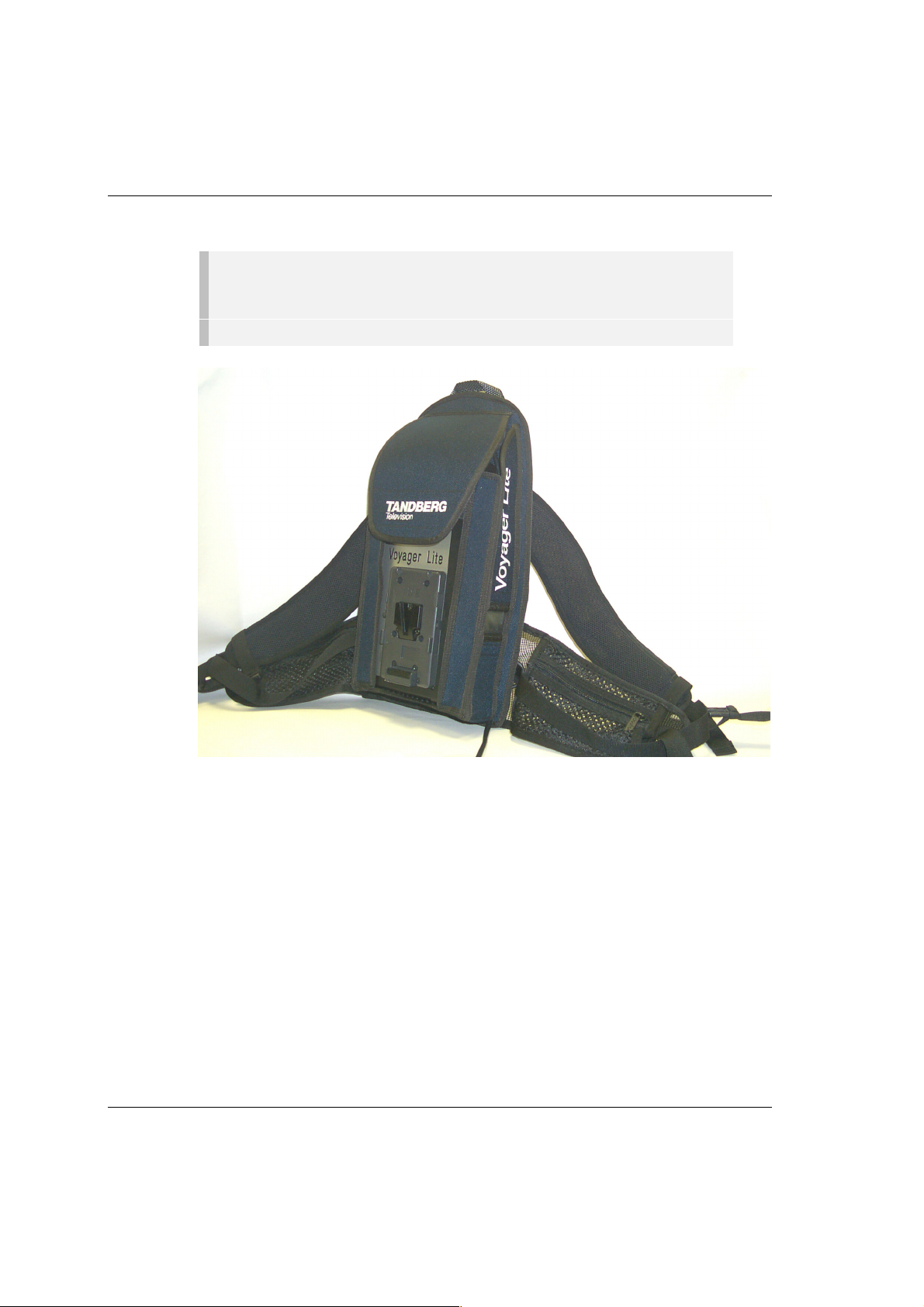
Figure 1.1: Voyager Lite – Typical Backpack/Portable Arrangement
The TANDBERG Voyager Li te System is designed for use as a
portable transmitter for a wireless camera, particularly suitable
for the news and sports broadcaster and security services. The
system comprises the followi ng components:
· Small low-powered Transmitter Unit with battery attachment
including an Encoder, integrated DVB-T OFDM Modulator and
Up-converter providing RF output from 2.1 – 2.5 GHz.
· Purpose built Backpack with integrated diversity antennas.
The antennas are located within the webbing straps of the
Backpack.
Page 1-4 ST.TM.2001.1: Voyager Lite System
Introduction
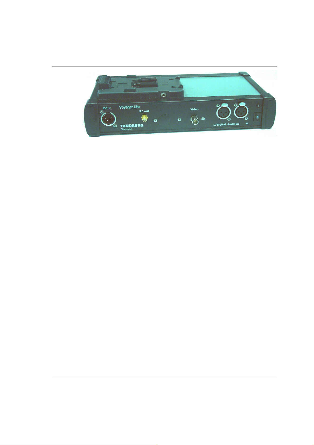
Figure 1.2: Voyager Lite (Minus Battery) – Disconnected from Backpack
The Voyager Lite provides:
· Audio and video interfaces
· Audio processing
· MPEG-2 video compression
· DVB-T compliant COFDM modulation
· RF radio output from 2.1 – 2.5 GHz, via an RF Up-converter
and radio amplifier.
All these features are contained within a single, dc battery
powered, robust, portable housing.
The fourth generation Encoder is a field-proven product that
contains the required signal processing capability to digitally
encode programme material using MPEG-2 compression
techniques.
The integrated DVB-T compliant, COFDM Modulator, Up-converter
(2.1 – 2.5 GHz) and Power Amplifier (up to 200 mW) enable
transmission to the terrestrial network.
ST.TM.2001.1: Voyager Lite System Page 1-5

Introduction
The various Marketing Codes used to id entify the unit are shown
in
Table 1.1.
Table 1.1: Equipment Model Numbering
Model Name Marketing Codes Description
Voyager Lite System M2/VLSYS/B8M
Receiver M2/PTRE/948CVL Alteia Plus PTRE948C for Voyager Lite
Down-converter M2/VLRX/DWNCNVIF IF Down-converter for Voyager Lite
Combined Battery and Charger
package
Microphone Adaptor for
Sennheiser, EK3041 RF
Wireless Microphone/Receiver
DENG Portable Receiver M2/CPTRX/8M Compact Receiver for Voyager Lite
2404 Omnidirectional Antenna M2/VLA/2404OM VLA2404 LP Omnidirectional Antenna
2404 Omnidirectional Antenna
with SMA
2405 Omnidirectional Antenna M2/VLA/2405OM VLA2405 LP Omnidirectional Antenna
2408 Omnidirectional Antenna M2/VLA/2408OM VLA2408 LP Omnidirectional Antenna
2409 Directional Antenna M2/VLA/2409DIR VLA2409 CP-R Directional Antenna
2417 Directional Antenna M2/VLA/2417DIR VLA2417 CP-R Directional Antenna
2417 Sectional Antenna M2/VLA/2417S VLA2417 LP Sectional Antenna
2418 Directional Antenna M2/VLA/2418DIR VLA2418 CP-R Directional Antenna
2417 CP-R Antenna Bracket M2/VLMB/2417 Mounting Bracket for VLA2417 CP-R
2417 LP Antenna Bracket M2/VLMB/2417LP Mounting Bracket for VLA2417 LP Sectional
2418 CP-R Antenna Bracket M2/VLMB/2418 Mounting Bracket for VLA2418 CP-R
Tripod Bracket M2/VLLB/MDT L-Bracket for use with Medium Duty Tripod
Low Noise Amplifier M2/VLRX/LNA2420F Low Noise Amplifier 2.3 - 2.5 GHz
M2/VLTX/IDXBAT02
M2/VLTX/WMRA Wireless Microphone Receiver Adaptor
M2/VLA/2404OMC VLA2404 LP Omnidirectional Antenna with
Voyager Lite complete Transmit and Receive
System with M2/PTRE/948CVL.
Voyager Lite Battery Pack and Charger
Options (combined)
SMA Connector
Directional Antenna
Antenna
Directional Antenna
NOTE..
It is also possible to use an external RF Amplifier and Transmit Antenna but these are
not offered as part of a standard system option.
Page 1-6 ST.TM.2001.1: Voyager Lite System

Introduction
V
Role of the Voyager Lite
Typical System
Description
The Voyager Lite is a portable unit, specifically designed for
mobile contribution applications. It is compact, fully MPEG-2 and
DVB-T compliant and has high performance for the transmission
of studio-quality programme material. The equipment is designed
to be suitable for full portable and mobile use on Outside
Broadcast productions.
oyager Lite
Video
Audio
COFDM
Encoder
Tx Antenna
Up-converter
and RF
Amplifier
Radio RX
Down-
converter
Rx Antenna
Demod
and
Decoder
Video
Audio
Figure 1.3: Typical System Configuration
Local control of the Encoder is implemented through ten
user-defined configurations (0 through 9) selectable from a switch
on the front panel.
Remote control is available via an RS-232 interface.
The RF output frequency of the unit can be set within the range
2.1 to 2.5 GHz. The power output level can also be adjusted up to
200 mW. However, both RF output frequency and output level
may be fixed and/or password protected dependent upon
application specific regulatory requirements.
CAUTION…
Certain broadcast applications and operational jurisdictions may restrict the output
frequency and power levels that are allowed. In this instance the manufacturer usually sets
these parameters.
ST.TM.2001.1: Voyager Lite System Page 1-7

Introduction
Encoder Features
High quality video encoding is ensured by the inclusion of many
proprietary algorithms as well as standard MPEG compression
techniques. The Encoder uses hierarchi cal moti on esti mation.
Video input to the unit is in either analogue composite video
(PAL B/D/G/H/I/M/N/N(Jamaica) or NTSC-M) or serial digital
(SDI).
The audio function supports multiple sampling frequencies,
bit-rates and coding modes. Audio can be input as balanced
analogue via the left and right XLR connectors, digital (AES/EBU)
via the left XLR connector or as SDI embedded audio.
The encoded video and audio is multiplexed within the Encoder.
The resulting multiplexed transport stream in DVB format is fed
directly to the internal COFDM Modulato r . Once COFDM coding
has taken place, the signal is fed to the internal IF Modulator
(70 MHz IF Output) for conversion to 2.1 - 2.5 GHz RF output,
ready for onward transmission using internal Up-converter and RF
amplifier.
COFDM Explanation
DVB-T compliant, Coded Orthogonal Frequency Division
Multiplexing (COFDM) is used to spread the transport stream data
over 1705 carriers (2k mode). This means that relatively low data
rates can be used on each carrier frequency, and any multipath
effects (ghosting) which occur affects only a small amount of
data.
The carriers are closely spaced so that their sidebands overlap,
but due to the orthogonal relationship between carrier frequencies
they do not interfere with each other. This makes the system
spectrally efficient.
Noise, multipath effects, co-channel interference and other
impairments can cause some bits to be received in error.
Therefore, Forward Error Correction (FEC) consisting of
Reed-Solomon (RS) coding followed by convol uti onal codi ng i s
used to add extra bits to the transmitted signal. This allows a
large number of errors at the receive end to be corrected by
convolutional (Viterbi) decoding followed by RS decoding.
Five convolutional code rates are available: 1/2, 2/3, 3/4, 5/6 and
These provide different compromises between bit-rate and
7/8
.
ruggedness.
Page 1-8 ST.TM.2001.1: Voyager Lite System

Introduction
The modulation scheme used in the Modulator on each of its
multiple data carriers is either Quadrature Amplitude Modulation
(16QAM) or Quadrature Phase Shift Keying (QPSK). QAM is a
mixture of amplitude and phase modulation. QPSK uses phase
modulation at constant amplitude. Both schemes are supported,
to allow the system to provide different compromises between
bit-rate and ruggedness.
Four guard intervals are available: 1/32, 1/16, 1/8, and 1/4
These are used to reduce the effects of intersymbol interference
at the receive end caused by multipath propagation. A guard
interval of 1/4 offers a robust transmission with the highest level
of protection.
NOTE…
The guard interval on the Voyager Lite must be set to the same value as the Receiver.
COFDM Modes and their Effect on Bit-rate
NOTE…
At time of publication the Alteia Receiver for use with Voyager Lite (M2/PTRE/948CVL)
is currently only designed for use at 8 MHz channel spacing within the system. The
tables for 7 MHz and 6 MHz operation are, therefore, provided for information only,
should an alternative Receiver be used.
Typical bit-rate outputs for 8 MHz, 7 MHz and 6 MHz channel
spacing are given in Table 1.2, Table 1.3 and Table 1.4
respectively. These illustrate how output bit-rate is affected by
modulation scheme, FEC (convolutional code) rate and guard
interval.
.
ST.TM.2001.1: Voyager Lite System Page 1-9

Introduction
Table 1.2: 8 MHz Channel Spacing
Guard interv al
¼ 1/8 1/16 1/32
Input Mod FEC Bit-rate Bit-rate Bit-rate Bit-rate
188-byte QPSK 1/2 4.976471 5.529412 5.854671 6.032086
188-byte QPSK 2/3 6.635294 7.372549 7.806228 8.042781
188-byte QPSK 3/4 7.464706 8.294118 8.782007 9.048128
188-byte QPSK 5/6 8.294118 9.215686 9.757785 10.053476
188-byte QPSK 7/8 8.708824 9.676471 10.245675 10.556150
188-byte 16QAM 1/2 9.952941 11.058824 11.709343 12.064171
188-byte 16QAM 2/3 13.270588 14.745098 15.612457 16.085561
188-byte 16QAM 3/4 14.929412 16.588235 17.564014 18.096257
188-byte 16QAM 5/6 16.588235 18.431373 19.515571 20.106952
188-byte 16QAM 7/8 17.417647 19.352941 20.491349 21.112299
Bit-rate Bit-rate Bit-rate Bit-rate
204-byte QPSK 1/2 5.400000 6.000000 6.352941 6.545455
204-byte QPSK 2/3 7.200000 8.000000 8.470588 8.727273
204-byte QPSK 3/4 8.100000 9.000000 9.529412 9.818182
204-byte QPSK 5/6 9.000000 10.000000 10.588235 10.909091
204-byte QPSK 7/8 9.450000 10.500000 11.117647 11.454545
204-byte 16QAM 1/2 10.800000 12.000000 12.705882 13.090909
204-byte 16QAM 2/3 14.400000 16.000000 16.941176 17.454545
204-byte 16QAM 3/4 16.200000 18.000000 19.058824 19.636364
204-byte 16QAM 5/6 18.000000 20.000000 21.176471 21.818182
204-byte 16QAM 7/8 18.900000 21.000000 22.235294 22.909091
Page 1-10 ST.TM.2001.1: Voyager Lite System

Introduction
Table 1.3: 7 MHz Channel Spacing (For Information Only)
Guard interv al
1/4 1/8 1/16 1/32
Input Mod FEC Bit-rate Bit-rate Bit-rate Bit-rate
188-byte QPSK 1/2 4.354412 4.838235 5.122837 5.278075
188-byte QPSK 2/3 5.805882 6.450980 6.830450 7.037433
188-byte QPSK 3/4 6.531618 7.257353 7.684256 7.917112
188-byte QPSK 5/6 7.257353 8.063725 8.538062 8.796791
188-byte QPSK 7/8 7.620221 8.466912 8.964965 9.236631
188-byte 16QAM 1/2 8.708824 9.676471 10.245675 10.556150
188-byte 16QAM 2/3 11.611765 12.901961 13.660900 14.074866
188-byte 16QAM 3/4 13.063235 14.514706 15.368512 15.834225
188-byte 16QAM 5/6 14.514706 16.127451 17.076125 17.593583
188-byte 16QAM 7/8 15.240441 16.933824 17.929931 18.473262
Bit-rate Bit-rate Bit-rate Bit-rate
204-byte QPSK 1/2 4.725000 5.250000 5.558824 5.727273
204-byte QPSK 2/3 6.300000 7.000000 7.411765 7.636364
204-byte QPSK 3/4 7.087500 7.875000 8.338235 8.590909
204-byte QPSK 5/6 7.875000 8.750000 9.264706 9.545455
204-byte QPSK 7/8 8.268750 9.187500 9.727941 10.022727
204-byte 16QAM 1/2 9.450000 10.500000 11.117647 11.454545
204-byte 16QAM 2/3 12.600000 14.000000 14.823529 15.272727
204-byte 16QAM 3/4 14.175000 15.750000 16.676471 17.181818
204-byte 16QAM 5/6 15.750000 17.500000 18.529412 19.090909
204-byte 16QAM 7/8 16.537500 18.375000 19.455882 20.045455
ST.TM.2001.1: Voyager Lite System Page 1-11

Introduction
Table 1.4: 6 MHz Channel Spacing (For Information Only)
Guard interv al
1/4 1/8 1/16 1/32
Input Mod FEC Bit-rate Bit-rate Bit-rate Bit-rate
188-byte QPSK 1/2 3.732353 4.147059 4.391003 4.524064
188-byte QPSK 2/3 4.976471 5.529412 5.854671 6.032086
188-byte QPSK 3/4 5.598529 6.220588 6.586505 6.786096
188-byte QPSK 5/6 6.220588 6.911765 7.318339 7.540107
188-byte QPSK 7/8 6.531618 7.257353 7.684256 7.917112
188-byte 16QAM 1/2 7.464706 8.294118 8.782007 9.048128
188-byte 16QAM 2/3 9.952941 11.058824 11.709343 12.064171
188-byte 16QAM 3/4 11.197059 12.441176 13.173010 13.572193
188-byte 16QAM 5/6 12.441176 13.823529 14.636678 15.080214
188-byte 16QAM 7/8 13.063235 14.514706 15.368512 15.834225
Bit-rate Bit-rate Bit-rate Bit-rate
204-byte QPSK 1/2 4.050000 4.500000 4.764706 4.909091
204-byte QPSK 2/3 5.400000 6.000000 6.352941 6.545455
204-byte QPSK 3/4 6.075000 6.750000 7.147059 7.363636
204-byte QPSK 5/6 6.750000 7.500000 7.941176 8.181818
204-byte QPSK 7/8 7.087500 7.875000 8.338235 8.590909
204-byte 16QAM 1/2 8.100000 9.000000 9.529412 9.818182
204-byte 16QAM 2/3 10.800000 12.000000 12.705882 13.090909
204-byte 16QAM 3/4 12.150000 13.500000 14.294118 14.727273
204-byte 16QAM 5/6 13.500000 15.000000 15.882353 16.363636
204-byte 16QAM 7/8 14.175000 15.750000 16.676471 17.181818
Page 1-12 ST.TM.2001.1: Voyager Lite System

Introduction
Summary of Features
Video Encoding
MPEG-2 Encoding
The Encoder processes a broadcast-standard video signal into a
compressed encoded bit-stream in accordance with:
· The MPEG-2 Main profile @ Main level (MP@ML) specification
(ISO/IEC 13818) and
· The MPEG-2 4:2:2 profile @ Main Level (422P@ML)
specification (ISO/IEC 13818)
Video Encoding Modes
Two video-encoding modes are available; they are 4:2:0 and
4:2:2, either of which can be selected. The coding mode selected
affects the compression techniques, Encoder delay and rate
control.
Table 1.5 and Tabl e 1.6 contain more information on modes and
compression uses.
Table 1.5: 4:2:2 Mode
Compression Mode Description Use
Standard Normal delay. No special techniques or fixed
settings used to reduce encoding delay.
Low Delay Delay lowered by reducing the video rate
buffer. Can compromise video quality in
some circumstances.
Ultra Low Delay
ST.TM.2001.1: Voyager Lite System Page 1-13
Various special techniques used to reduce
the delay mode. May not work with all
Decoders, especially older models or
third-party Decoders.
Mixture of fixed and wireless
cameras used.
Two-way transmission (e.g. an
interview).

Introduction
Table 1.6: 4:2:0 Mode
Compression Mode Description Use
Standard
Low Delay
Ultra Low Delay
Normal delay. No special techniques or fixed
settings used to reduce encoding delay.
Various special techniques used to reduce
the delay mode. May not work with all
Decoders, especially older models or
third-party Decoders.
GOP structure: B-frames cannot be used in
this mode.
The same techniques used as in Low Delay
Mode, but with the delay further reduced at
lower bit-rates.
Video Inputs
The video input connections are:
· SDI
· VBS Composite
The supported video input types are:
·
Serial digital
(ITU-R BT.656-4) input (
·
625-line composite
(ITU-R BT. 624-4)
· 525-line composite
PAL-M (ITU-R BT. 624-4)
·
Internal test p at te rn function
PAL-B, -D, -G, -H, -I, -N, -N (Jamaica)
NTSC-M (with and without ped estal) or
D1 serial format
Mixture of fixed and wireless
cameras used.
Two-way transmission (e.g. an
interview).
As for Low Delay.
) – ANSI/SMPTE 259M
·
Monochrome
Video Encoding Functions
The standard video encoding functions include:
· Support for all MP@ML and 422P@ML standard coding modes
· Selectable bit-rate operation, 1.5 Mbit/s - 21 Mbit/s
(depending upon Encoder mode and modulation used, see
Table 1.7)
· Support for the standard set of video picture resolutions (720,
704, 640, 544, 480 and 352) in both 625 and 525 line
operation
Page 1-14 ST.TM.2001.1: Voyager Lite System

Introduction
· Hierarchical motion estimation
· Support for a variety of Group of Pictures (GOP) structures
with a variable number of B frames
· The ability to generate internal video test patterns
Video Variable Bit-rate
The MPEG-2 compression algorithm uses adaptive field/frame
coding, forward and backward predictive processing with motion
estimation and compensation to reduce the bit-rate to the range
shown in Table 1.7.
Table 1.7: Video Bit-rate Range
Video Encoding Mode
4:2:0 4:2:2
1.5 Mbit/s - 15 Mbit/s 1.5 Mbit/s – 21 Mbit/s
Coding Resolutions
To provide optimum picture quality over the full range of
supported bit-rates; the encoded picture resolution can be varied
according to the video bit-rate. Typical settings are shown in
Table 1.8.
Table 1.8: Video Coding Resolutions and Typical Bit-rates
625 Line Modes 525 Line Modes Typical Bit-rate
4:2:0 (Mbit/s)
720 pixels x 576 lines 720 pixels x 480 lines 6.0 – 15.0 6.0 – 21.0
704 pixels x 576 lines 704 pixels x 480 lines 6.0 – 15.0 6.0 – 21.0
640 pixels x 576 lines 640 pixels x 680 lines 5.0 – 15.0 5.0 – 21.0
544 pixels x 576 lines 544 pixels x 480 lines 4.0 – 15.0 4.0 – 21.0
480 pixels x 576 lines 480 pixels x 480 lines 2.5 – 15.0 2.5 – 21.0
352 pixels x 576 lines 352 pixels x 480 lines 1.5 – 15.0 1.5 – 21.0
Typical Bit-rate
4:2:2 (Mbit/s)
System configuration can be stored in Flash, for restoration of
configured state at power-on.
ST.TM.2001.1: Voyager Lite System Page 1-15

Introduction
Output on Video Loss
If video input is lost, the Encoder can be software-configured to
show either a test pattern (colour bars and red) or black. There is
also an option to switch the caption showing the service name
ON or OFF.
Audio Encoding
General
Audio can be encoded to any of the following:
· MPEG-1 Audio Layer 2 (Musicam) standard (sampling rate
32 kHz or 48 kHz) or
· Dolby Digital (sampling rate of 32 kHz or 48 kHz). Output bit-
rate is selectable in the range 64 kbit/s to 384 kbit/s
(dependent on configuration) for MPEG-1 Audio (layer 2) and
96 kbit/s to 640 kbit/s (dependent upon configuration) for
Dolby Digital.
· Pre-compressed (or pre-encoded – IEC 61937) audio in pass-
through mode is also available. This is where an audio stream
has already been encoded externally, prior to entering the
Encoder and is passed through to the output. This type of
audio is supported in Dolby Digital and can be embedded with
the incoming SDI video information.
· Linear PCM (SMPTE 302M).
· Dolby E Pass Through.
Audio Inputs
The standard audio input is:
· AUDIO IN – Two female XLR connectors – selectable via the
Audio Menu (see Chapter 2, Set-up, Configuration and
Operation) - balanced analogue or digital AES/EBU, with
AES/EBU on the left connector only.
· Alternatively, audio can be input embedded as AES/EBU on
the serial digital input (SDI). In this mode, two of four stereo
pairs can be extracted. Audio may be converted to either of
the standard output frequencies, 32 kHz or 48 kHz, by use of
the built-in asynchronous sample rate converters.
Page 1-16 ST.TM.2001.1: Voyager Lite System

Introduction
Audio Channels
The Encoder supports two channels of audio, which may be
configured as one of the following:
· Two analogue mono channels, 600 W or 20 kW
· One analogue stereo pair, 600 W or 20 kW
· One digital channel, AES/EBU or embedded SDI
MPEG Encoding Modes
The two stereo pairs may be configured in various encoding
modes:
· Single mono: the left channel is encoded – the signal is
output to Left and Right connectors at the receiving end.
· Dual mono: the left and right signals are encoded and
carried in the transport stream as a single Packetised
Elementary Stream (PES) data stream. The way that the left
and right signals are output from the Receiver is dependent
on how the routing is set-up in the Receiver. Both the left and
the right may be output, or the left only, or the right only.
This is typically used for multilingual services.
· Stereo: A stereo pair is coded as two mono signals - the two
signals are output as stereo at the receiving end.
· Joint/intensity stereo: A stereo pair is coded taking
advantage of the stereo nature of the channels – the two
signals are output as stereo at the receiving end.
Test Tone
An internally generated test tone is available for alignment
purposes. Refer to Annex B, Technical Specification for level and
frequency.
ST.TM.2001.1: Voyager Lite System Page 1-17

Introduction
Audio Variable Bit-rate
MPEG-2 audio output bit-rate (see Table 1.9) is selectable in the
range 32 kbit/s - 384 kbit/s (dependent on configuration).
Table 1.9: MPEG-2 Audio Encoding Bit-rates
Bit-rate
(kbit/s)
32 ü --48 ü --56 ü --64 üüüü
80 ü --96 üüüü
112 üüüü
128 üüüü
160 üüüü
192 üüüü
224 - üüü
256 - üüü
320 - üüü
384 - üüü
Test Patterns
Internally generated test patterns can be accessed via the Video
Source Menu (see Chapter 2, Set-up, Configuration and
Operation). The patterns available are:
· Colour Bars and Red (625 lines)
Single Channel
Mono
Dual Channel
Mono
Dual Channel
Stereo
Dual Channel
Joint Stereo
· Colour Bars and Red (525 lines)
· Black Screen
Page 1-18 ST.TM.2001.1: Voyager Lite System

Introduction
Configuration and Control
There are ten selectable configurations (0 through 9), stored in
Flash memory and selected by an external switch. This enables
quick set-up of the Voyager Lite.
An additional RS-232 interface is provided, allowing control and
configuration from a remote terminal (HyperTerminal).
NOTE…
Any terminal emulator may be used. For purposes of this manual the remote emulator
will be referenced as HyperTerminal which is a commonly used Hilgraeve application.
ST.TM.2001.1: Voyager Lite System Page 1-19
Introduction
r
A
A
Guided Tour
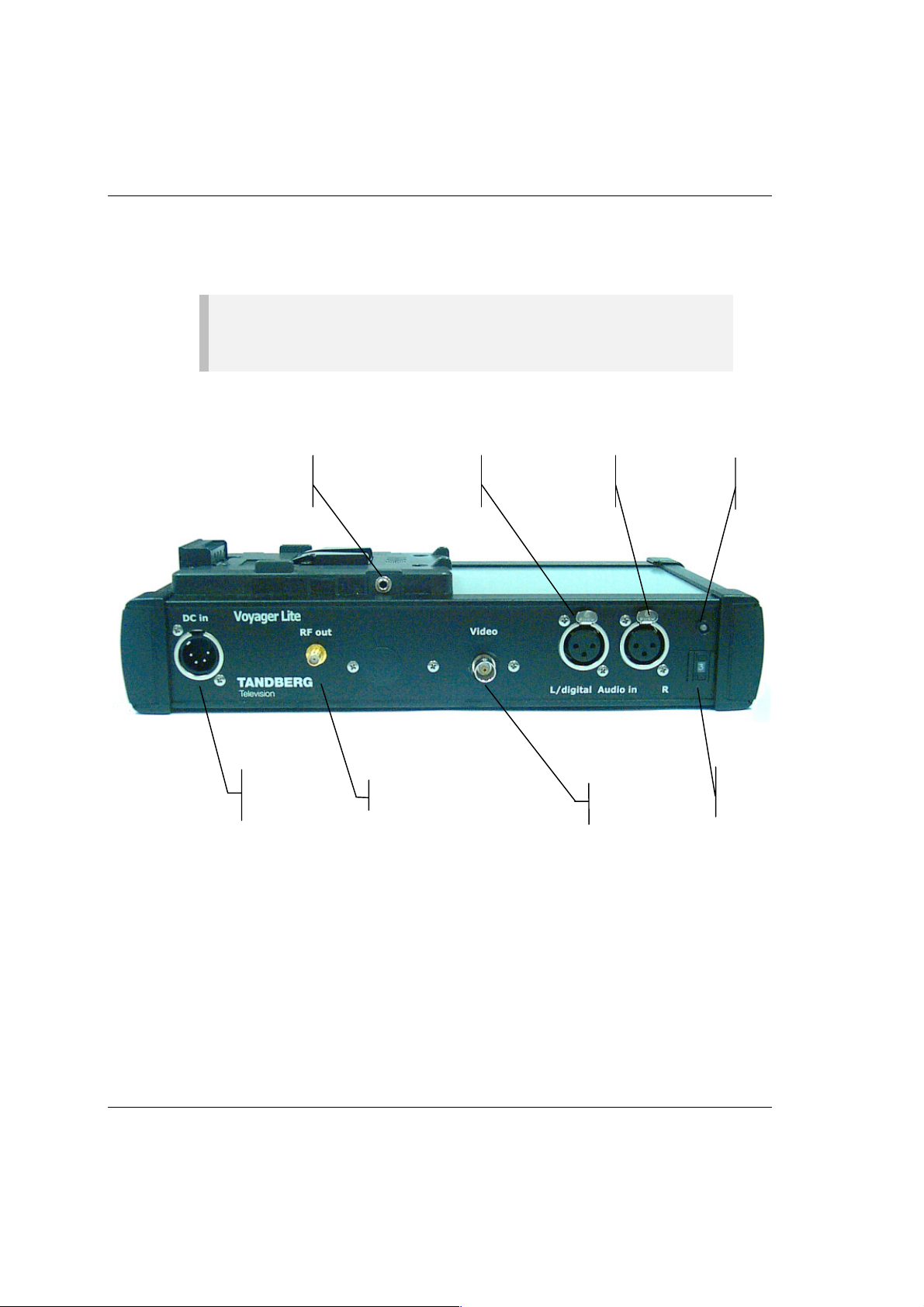
Right Side Panel
NOTE…
The unit described in this section, is a typical configuration for the Voyager Lite. Some
controls and connectors may differ from those shown and vary in their location.
The right side panel of the unit is shown in Figure 1.4 without the
battery fitted.
Low Battery
Vibration Alarm
Connector
Connects to
DC Power
Source
nalogue
Audio Left IN /
AES/EBU IN
RF Out to
Antennas
Figure 1.4: Right Side View (Without Battery Fitted)
nalogue
Audio Right IN
SDI o
Composite
Video IN
Status
LED
Configuration
Selector
Switch
Page 1-20 ST.TM.2001.1: Voyager Lite System
 Loading...