

Page 1

Tandberg Data M-Series Remote Management Card Quick Reference Guide
This Quick Reference Guide
explains how to install the
M-Series Remote Management
Card (RMC) into a Tandberg Data
M-Series tape library.
For your convenience, this task
has been condensed into a few
simple steps. As you perform each
step, watch for instructions that
specifically address a first-time
installation or a field replacement.
If you need help with any part of
these instructions, please contact
Tandberg Customer Support. You
can also receive help in the form of
a complete set of M-Series library
user documents in Portable
Document File (PDF) format by
going to www.tandberg.com.
Once the RMC is installed, it must
be configured using instructions
found in the Tandberg Data
M-Series Remote Management
Card User’s Guide. This User’s
Guide and other applicable
documentation are available in
PDF format on the CD shipped in
the Tandberg Data Field Upgrade
Kit.
N
OTE: Adobe Acrobat Reader is
required to view and print PDF
documents. To download a free
copy of Adobe Acrobat Reader, go
to www.adobe.com.
STEP 1: PREPARE FOR INSTALLATION/REPLACEMENT
a. If this is a first-time installation, make sure your library has firmware version
3.03 or later. For a complete list of system requirements, refer to the Tandberg
Data M-Series Remote Management Card User’s Guide, P/N T6473046.
b. Make sure you have the tools recommended for this procedure:
-- #1 Phillips
-- Slotted screwdriver.
-- T10 TORX
cover of the desktop model of the M-Series library.)
RMC
Main Installation/FRU Components
c. Take precautions to prevent electrostatic discharge (ESD). These precautions
include:
-- Wearing a properly grounded antistatic wrist strap.
-- Wearing other antistatic apparel (smock, footwear, etc.).
-- Handling library components with care and keeping the RMC in its antistatic
packaging until you are ready to install it.
C
AUTION: Failure to take adequate antistatic precautions may result in
damage to the RMC or other library components.
®
screwdriver.
®
screwdriver. (This tool may be required to remove the outer
P2
P1
Interconnect cable
Page 2

STEP 2: INSTALL THE RMC
a. Loosen the two captive screws that secure
the card cage to the back of the library.
M1500
back panel
Cover plate
mounting
screw
b. Slide the card cage out of the library using
the handle.
c. Locate the expansion slot on the far right-
hand side of the card cage. This is on your
right as you face the back panel.
If this is a first-time installation, remove
the slot cover plate and hold-down clamp.
To do this, remove the mounting screws
securing the cover plate to the card cage
Handle
and then lift the plate out. Then, remove
the screws that secure the hold-down
clamp to the side of the card cage. Save
the clamp and mounting screws for use
later in this installation. Save the cover
M-Series Library Expansion Card Cage
M2500
back panel
OTE: The card cage is identical
N
for the M1500 and M2500 libraries.
plate for future use.
If you are replacing an RMC, remove the existing RMC as follows. Disconnect the interconnect cable from the
existing RMC and the library serial port. Remove the hold-down clamp screws from the side of the card cage and set
the hold-down clamp aside. Remove the screws that secure the RMC to the card cage, and then lift the RMC out of the
library expansion slot. Set the RMC and cable that you just removed aside.
N
OTE: Refer to the Return Material Authorization (RMA) documents shipped with the replacement RMC for the
appropriate return procedure.
Captive
screws
Slot for
RMC
Cover plate
mounting
screw
d. Carefully remove the new RMC from its antistatic packaging. Hold the
RMC by the edges; avoid contact with RMC components and connectors.
e. Insert the RMC into the expansion slot. Press down gently on the card
edge until the card is securely seated.
f. Secure the RMC to the card cage frame using the two mounting screws
removed earlier.
g. If you plan to install one or more Fibre Channel bridges (FC310 or
FC420), do so now following the instructions found in the Quick
Reference Guide shipped with the Fibre Channel bridge.
h. Reattach the hold-down clamp to secure the card in the slot.
i. Slide the card cage back into the library and secure the cage by
tightening the two captive screws.
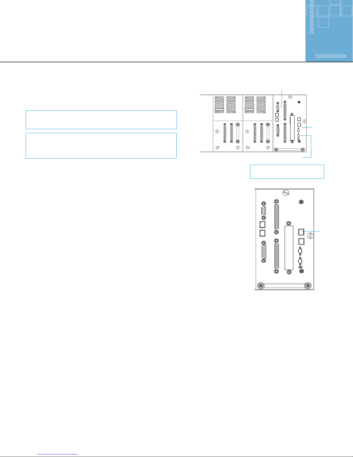
Mounting screw
Ethernet 0 (ETH 0)
Ethernet 1 (ETH 1)
Command serial
port (RS-232)
Diagnostic serial
port (RS-232)
LEDs
Mounting screw
RMC Ports and Indicators
Page 3
STEP 3: ATTACH THE INTERCONNECT CABLE
Library serial port (attach P2 cable connector)
Once you have installed the RMC, attach the interconnect cable from
the diagnostic serial port on the RMC to the library serial port.
OTE: The connectors are different sizes; the cable can
N
only be connected in the proper orientation.
N
OTE: If you are replacing the RMC, be sure to use the
new interconnect cable shipped with the replacement
RMC.
RMC serial port (attach P1 cable connector)
STEP 4: ESTABLISH A RMC-TO-HOST CONNECTION FOR
LIBRARY MANAGEMENT
a. Connect an Ethernet cable from the ETH 0 port on the RMC to one of the following:
-- A TCP/IP network segment with a Dynamic Host Configuration Protocol (DHCP)
server
-- A non-DHCP computer directly connected to the RMC using a hub or crossover
cable
RMC
NOTE: For clarity, the interconnect
cable is not shown.
ETH 0
b. Make sure the host computer is turned on.
c. Turn on the library. The RMC broadcasts a DHCP request. If you are using a DHCP
server, the server will assign an IP address to the RMC.
d. Get the IP address assigned to the RMC.
If the host computer is on the same network as a DHCP server, go to the DHCP
Manager window on the DHCP server and find the IP address assigned to the RMC. As
RMC Ethernet 0 (ETH 0) Port
an alternative, you can also obtain this information from the library’s operator control
panel by selecting Main > QuickView > Library > Network.
If the host computer is not on a DHCP network, configure the RMC with network information (IP address, subnet
mask, and gateway) compatible with the host computer as follows:
-- At the operator control panel of the library, select Main > Menu > Config.
-- When the Configuration screen appears, scroll down until IP Address is highlighted and then press Select. This
causes the first portion of the IP Address to be highlighted.
-- Use the Up and Down buttons to increase or decrease the value of the selected portion of the IP address. Then, press
Select to jump to the next portion of the IP address. Continue using the Up, Down, and Select buttons to modify the
rest of the IP address. Pressing Select after modifying the last portion of the IP address saves the new IP address and
highlights the entire parameter. (Be sure to select an available IP address in this same class as the host computer’s
network.)
-- Using the same procedure, select and modify the Subnet Mask and Gateway parameters as appropriate.
Page 4

-- Wait about one minute after modfying these parameters and then restart the library.
OTE: As a third option, you can configure a host computer (such as a laptop) to be compatible with the default static
N
IP address of the RMC. To do this, wait appropriately 30 seconds after starting the library for the DHCP request from
the RMC to time out. The RMC then assigns itself the static IP address of 192.168.1.1.
Set the following parameters on the host computer:
-- IP address: 192.168.1.2
-- Subnet mask: 255.255.255.0
-- Gateway: default settings for the computer
Using a PING command, verify communication between the host computer and the RMC.
STEP 5: CREATE SCSI BUSSES AND SCSI-TO-FIBRE CONNECTIVITY
If you installed a Fibre Channel bridge, establish SCSI-to-Fibre connectivity as explained in the Quick Reference Guide for the
Fibre Channel bridge.
STEP 6: CONFIGURE THE RMC
Once installed, configure the RMC using the instructions found in the M-Series Remote Managment Card User’s Guide,
P\N T6473046.
Tandberg Data GmbH
Feldstr. 81, D-44141
Dortmund
Germany.
Tel: +49 231 5436 0
Fax: +49 231 5436 111
Copyright 2002 Quantum Corporation. All rights reserved. ATL Tape Libraries, and Prism Storage Architecture are trademarks of Quantum Corporation registered in the U.S.A and
other countries. Products mentioned herein are for identification purposes only and may be registered trademarks or trademarks of their respective companies. All other brand names
or trademarks are the property of their respective owners.
PN T6473047-01, Ver. 1, Rel. 0 6207947-02sN 01
Tandberg Data ASA
KjelsÂsveien 161
P.O. Box 134 KjelsÂs
N-0411 Oslo
Norway
Tel: +47 22 18 90 90
Fax: +47 22 18 95 50
Tandberg Data S.A.S.
16/18 Ave.
Morane-Saulnier
F-78941 VÈlizy Cedex
France
Tel: +33 1 39 26 01 01
Fax: +33 1 34 65 02 89
Tandberg Data (Asia) Pte. Ltd.,
801 Lorong 7
Toa Payoh #02-00
Singapore 319319
Tel: +65 259 9330
Fax: +65 258 1702
Tandberg Data (Japan) Inc.
Shinkawa-nittei Annex Bldg., 7th floor,
22-4 Shinkawa 1-chome, Chuo-ku
Tokyo 104-0033 Japan
Tel: +81 3 5566 2871
Fax: +81 3 5566 2875
 Loading...