

Page 1

Tandberg Data M-Series
User’s Guide
T6423045-03 A01
Page 2

Tandberg Data M-Series User’s Guide, T6423045-03 A01, February 2004, Made in USA.
Tandberg Data provides this publication “as is” without warranty of any kind, either express or implied,
including but not limited to the implied warranties of merchantability or fitness for a particular purpose.
Tandberg Data may revise this publication from time to time without notice.
COPYRIGHT STATEMENT
© Copyright 2004 by Quantum Corporation. All rights reserved.
Your right to copy this document is limited by copyright law. Making copies or adaptations without prior
written authorization of Quantum Corporation is prohibited by law and constitutes a punishable violation of
the law.
TRADEMARK STATEMENT
StackLink is a trademark of Quantum Corporation.
Other trademarks may be mentioned herein which belong to other companies.
6207947-00cN 95
Page 3

Contents
Preface xiii
Chapter 1 Overview 1
Library Capacity.................................................................................................1
M1500 Library ............................................................................................. 1
M2500 Library ............................................................................................. 1
Tape Drives.........................................................................................................2
Library Scalability.............................................................................................. 2
Library Features .................................................................................................5
Front Panel................................................................................................... 5
Internal Layout............................................................................................ 8
Back Panel..................................................................................................10
Chapter 2 Basic Operations 13
Introduction ...................................................................................................... 14
Main Screen ............................................................................................... 14
GUI Buttons ............................................................................................... 17
GUI Icons ................................................................................................... 17
Tandberg Data M-Series User’s Guide iii
Page 4

Contents
Using the Quick View Menu Screen..............................................................19
Accessing the Quick View Menu Screen ...............................................19
Viewing Library Information ..................................................................20
Viewing Tape Drive Information............................................................21
Viewing Inventory Information..............................................................22
Turning Drive Power On or Off (Quick View Menu Screen).............23
Moving Tape Cartridges .................................................................................25
Using the Mailbox ............................................................................................28
Viewing Mailbox Status ...........................................................................29
Importing and Exporting Cartridges .....................................................30
Configuring the Mailbox..........................................................................35
Removing the Magazines................................................................................35
Removing a Magazine from an M1500 .................................................. 36
Removing a Magazine from an M2500 .................................................. 38
Viewing Statistics .............................................................................................43
Accessing the Statistics Menu Screen.....................................................43
Viewing Library Statistics........................................................................44
Viewing Drive Statistics ...........................................................................45
Viewing the SCSI History ........................................................................46
Viewing the Stack Configuration...................................................................47
Chapter 3 Changing the Library Configuration 49
Accessing the Configuration Screen..............................................................49
Setting the Library ID ......................................................................................51
Changing a Tape Drive ID ..............................................................................51
Changing the Terminator Power Setting ......................................................53
Changing the Emulation Setting ....................................................................54
Changing the Storage Slot Count Setting .....................................................54
Changing the Sync Negotiation Setting........................................................55
Changing the Wide Negotiation Setting.......................................................56
Changing the Serialization Setting ................................................................57
Changing the Short Labels Setting.................................................................58
Changing the Illumination Setting ................................................................58
Changing the Off-Line Time Setting .............................................................59
Changing the Barcode Scanner Setting .........................................................60
Changing the Baud Rate Setting ....................................................................60
Setting the Time................................................................................................61
Setting the Date.................................................................................................62
iv Tandberg Data M-Series User’s Guide
Page 5

Contents
Changing the Import/Export Setting ........................................................... 62
Changing the Auto-Clean Setting.................................................................. 64
Changing the Ignore Host Lock Setting ....................................................... 65
Changing the Auto-Import Option ............................................................... 66
Chapter 4 Performing Maintenance Operations 67
Accessing the Maintenance Screen................................................................ 67
Cleaning a Tape Drive..................................................................................... 69
Turning Drive Power On or Off (Maintenance Screen) ............................. 71
Adjusting the Contrast .................................................................................... 73
Chapter 5 Running Diagnostic Programs 75
Accessing the Diagnostics Menu Screen....................................................... 75
Running the Barcode Scanner Test................................................................ 77
Running the Move Medium Test................................................................... 79
Running the Move Location Test................................................................... 82
Running the Display Test ............................................................................... 85
Chapter 6 Updating Drive Firmware 87
Accessing the Service Drive Screen............................................................... 87
Updating the Drive Firmware from Tape .................................................... 89
Chapter 7 Running the Demonstration Programs 91
Accessing the Demo Programs Screen.......................................................... 91
Running the Confidence Test Program ........................................................92
Running the Demo 1 Program ....................................................................... 93
Running the Demo 2 Program ....................................................................... 94
Running the Demo 3 Program ....................................................................... 95
Running the Demo 4 Program ....................................................................... 96
Running the Demo 5 Program ....................................................................... 97
Running the Demo 6 Program ....................................................................... 98
Tandberg Data M-Series User’s Guide v
Page 6

Contents
Appendix A Specifications 99
Physical Specifications...................................................................................100
Performance Specifications...........................................................................102
Reliability Specifications ...............................................................................103
Tape Drive Specifications..............................................................................104
Environmental Specifications .......................................................................104
SCSI Specifications .........................................................................................105
Appendix B Fault Symptom Code (FSC) Dictionary 107
Appendix C DLTtape Cartridge Maintenance 159
Handling DLTtape Cartridges......................................................................159
Visual Inspection of DLTtape Cartridges ...................................................160
When To Visually Inspect a DLTtape Cartridge ................................160
Visual Inspection Procedure..................................................................161
Appendix D Regulatory Statements 165
Glossary 169
Index 171
vi Tandberg Data M-Series User’s Guide
Page 7

Figures
Figure 1 M1500 Front Panel........................................................................ 5
Figure 2 M2500 Front Panel........................................................................ 6
Figure 3 M1500 Internal Layout................................................................. 8
Figure 4 M2500 Internal Layout................................................................. 9
Figure 5 M1500 Back Panel....................................................................... 10
Figure 6 M2500 Back Panel....................................................................... 11
Figure 7 Sample Main Screen, Stand-alone M1500...............................15
Figure 8 Sample Main Screen, M1500 in a Multiple Library Stack..... 15
Figure 9 M2500 Library Levels ................................................................ 16
Figure 10 Sample Main Screen, M2500 .....................................................16
Figure 11 Using the GUI Buttons............................................................... 17
Figure 12 Quick View Menu Screen..........................................................19
Figure 13 Sample Library Information Screen......................................... 20
Figure 14 Sample Drive Information Screen............................................ 21
Figure 15 Sample Inventory Screen........................................................... 22
Figure 16 Sample Tape Drive Power Screen............................................ 23
Figure 17 Sample Drive Power Screen...................................................... 24
Tandberg Data M-Series User’s Guide vii
Page 8

Figures
Figure 18 Menu Screen ................................................................................25
Figure 19 Sample Move Cartridge FROM Screen....................................26
Figure 20 Sample Move Cartridge TO Screen..........................................27
Figure 21 Sample Confirm Move Cartridge Screen ................................28
Figure 22 Sample Mailbox Screen..............................................................29
Figure 23 Mailbox - OPEN Screen .............................................................30
Figure 24 Sample Release Magazines Screen ........................................... 36
Figure 25 Magazine Release Button...........................................................38
Figure 26 Release Magazines Screen .........................................................39
Figure 27 Removing the Level 2 Left Magazine ......................................41
Figure 28 Release Latch ...............................................................................41
Figure 29 Removing the Level 1 Left Magazine ......................................42
Figure 30 Service Menu Screen ..................................................................43
Figure 31 Statistics Menu Screen................................................................44
Figure 32 Sample Library Statistics Screen...............................................44
Figure 33 Sample Drive Statistics Screen..................................................46
Figure 34 Sample SCSI History Screen......................................................47
Figure 35 Sample Stack Configuration Screen .........................................48
Figure 36 Menu Screen ................................................................................50
Figure 37 Configuration Screen..................................................................50
Figure 38 M2500 Drive Numbering...........................................................52
Figure 39 Service Menu Screen ..................................................................68
Figure 40 Maintenance Screen....................................................................68
Figure 41 Select Cleaning Cartridge Screen .............................................69
Figure 42 Select Tape Drive Screen............................................................70
Figure 43 Sample Tape Drive Power Screen ............................................71
Figure 44 Sample Drive Power Screen......................................................72
Figure 45 Adjust Contrast Screen...............................................................73
Figure 46 Service Menu Screen ..................................................................76
Figure 47 Diagnostics Menu Screen...........................................................76
viii Tandberg Data M-Series User’s Guide
Page 9

Figures
Figure 48 Diags: General Screen ................................................................ 77
Figure 49 Diag: Barcode Screen ................................................................. 78
Figure 50 Sample Move Cartridge FROM Screen ................................... 79
Figure 51 Move Cartridge TO Screen ....................................................... 80
Figure 52 Sample Confirm Move Cartridge Screen ................................ 81
Figure 53 Diag: Move Medium Screen ..................................................... 81
Figure 54 Diag: Move-Location Screen..................................................... 83
Figure 55 Diag: Move Location Screen ..................................................... 84
Figure 56 Service Menu Screen .................................................................. 88
Figure 57 Service Drive Screen................................................................... 88
Figure 58 Select Firmware Cartridge Screen............................................89
Figure 59 Select Tape Drive Screen ........................................................... 90
Figure 60 Demo Programs Screen ............................................................. 92
Figure 61 Location of the Reel Locks and the Hub ............................... 161
Figure 62 Opening the Tape Cartridge Door......................................... 162
Figure 63 Write Protect Switch ................................................................ 163
Tandberg Data M-Series User’s Guide ix
Page 10

Figures
x Tandberg Data M-Series User’s Guide
Page 11

Tables
Table 1 Capacity, M1500 Multiple Library Stack ..................................3
Table 2 Capacity, M2500 Multiple Library Stack ..................................4
Table 3 Front Panel Features ....................................................................7
Table 4 GUI Icons..................................................................................... 17
Table 5 Import/Export Settings ............................................................. 63
Table 6 Unit Dimensions/Weight ....................................................... 100
Table 7 Capacities................................................................................... 100
Table 8 Performance Specifications..................................................... 102
Table 9 Library Performance ................................................................ 102
Table 10 Reliability Specifications ......................................................... 103
Table 11 Tape Drive Specifications........................................................ 104
Table 12 Power ......................................................................................... 104
Table 13 Climate....................................................................................... 105
Table 14 Compliance and Certification................................................. 105
Table 15 Fault Symptom Codes .............................................................107
Tandberg Data M-Series User’s Guide xi
Page 12

Tables
xii Tandberg Data M-Series User’s Guide
Page 13

Preface
Audience This document is written for operators of the M1500 and M2500 libraries.
Purpose This document explains how to use the M1500 and M2500 libraries.
Document
Organization
This document is organized as follows:
• Chapter 1, Overview
• Chapter 2, Basic Operations
explains how to use them to perform basic library operations such as
moving tape cartridges within the library, removing the tape
cartridge magazines, and viewing library information.
• Chapter 3, Changing the Library Configuration
change the library configuration using the GUI
• Chapter 4, Performing Maintenance Operations
perform library maintenance operations using the GUI
screen.
• Chapter 5, Running Diagnostic Programs
library’s built in diagnostic programs.
Tandberg Data M-Series User’s Guide xiii
, provides an overview of the M-Series libraries.
, introduces the library GUI screens and
, explains how to
Configuration screen.
, explains how to
Maintenance
, explains how to use the
Page 14

Preface
• Chapter 5, Updating Drive Firmware, explains how to update the
drive firmware.
Notational
Conventions
• Chapter 6, Running the Demonstration Programs
, explains how to
run the library demonstration programs.
• Appendix A, Specifications
, lists the specifications for the M-Series
libraries.
• Appendix B, Fault Symptom Code (FSC) Dictionary
, lists the fault
symptom codes (FSCs) for the M-Series libraries.
• Appendix C, DLTtape Cartridge Maintenance
, provides guideline for
handling DLT and SDLT cartridges and visually inspecting them if
necessary.
• Appendix D, Regulatory Statements
, provides regulatory
information for the M-Series libraries.
This document concludes with a glossary and a detailed index.
This document uses the following conventions:
Note: Notes emphasize important information related to the main
topic.
Caution: Cautions indicate potential hazards to equipment and are
included to prevent damage to equipment.
Warning: Warnings indicate potential hazards to personal safety
and are included to prevent injury.
This manual uses the following:
• Right side of the library — Refers to the right side as you face the
component being described.
• Left side of the library — Refers to the left side as you face the
component being described.
xiv Tandberg Data M-Series User’s Guide
Page 15

Preface
Related
Documents
Documents related to the M-Series libraries are shown below.
M-Series Documentation
Document No. Title Description
T6421035 M1500 Unpacking
Instructions
T6423047 M2500 Unpacking
Instructions
T6423046 M-Series Installation
Guide
Refer to the appropriate product manuals for information about your
tape drive and cartridges.
SCSI-2 Specification
This document explains how
to remove the M1500 library
from the shipping carton.
This document explains how
to remove the M2500 library
from the shipping carton.
This document explains how
to install an M-Series library.
0
0
The SCSI-2 communications specification is the proposed American
National Standard for information systems, dated March 9, 1990. Copies
may be obtained from:
Global Engineering Documents
15 Inverness Way, East
Englewood, CO 80112
(800) 854-7179 or (303) 397-2740
Tandberg Data M-Series User’s Guide xv
Page 16

Preface
xvi Tandberg Data M-Series User’s Guide
Page 17

Chapter 1
Overview 1
This chapter provides an overview of the M-Series libraries and their
features.
Library Capacity 1
M1500 Library 1 The M1500 library can contain up to two tape drives and up to 21 DLT/
SDLT cartridges or 25 LTO cartridges. The cartridges are stored in two
independently removable cartridge magazines and one fixed cartridge
slot.
M2500 Library 1 The M2500 library can contain:
• Up to five tape drives and up to 84 DLT/SDLT cartridges or 100 LTO
cartridges
• Six tape drives and up to 73 DLT/SDLT cartridges or 87 LTO
cartridges
The cartridges are stored in up to eight independently removable
cartridge magazines and up to four fixed cartridge slots.
Tandberg Data M-Series User’s Guide 1
Page 18

Chapter 1 Overview
Tape Drives
Tape Drives 1
M-Series tape libraries are equipped with SCSI tape drives. One SCSI bus
is provided for the library robotics and for each tape drive installed.
These SCSI buses are Ultra 2 SCSI, Ultra 3 SCSI, or Ultra 160 SCSI,
depending on the drives installed.
LVD SCSI configurations have a maximum allowable bus length of 12
meters. To determine the cable length of the bus, measure the lengths of
the SCSI cables connecting each device to that bus and add those lengths
together. To that total length, add 12.25 inches (31.10 cm) for the internal
SCSI cable length of each SCSI tape drive.
Library Scalability 1
The M1500 and M2500 library modules can be used as stand-alone
libraries, or can be combined with other M1500 and M2500 library
modules and a StackLink mechanism in a standard 19-inch rack to form a
larger library system (called a multiple library stack). The multiple library
stack appears as a single large capacity library to the host.
The StackLink mechanism connects the library modules in the multiple
library stack and transports cartridges from module to module. Each tape
drive has access to all the tape cartridges in the stack.
Once the StackLink mechanism is installed in the rack, you can add
library modules simply by sliding them into place and making the
necessary electrical connections.
Table 1
create using M1500 library modules. Table 2
sizes of multiple library stack you can create using M2500 library
modules. You can obtain different capacities by combining M1500 and
M2500 library modules in a multiple library stack.
2 Tandberg Data M-Series User’s Guide
lists the capacities of all the sizes of multiple library stack you can
lists the capacities of all the
Page 19

Table 1 Capacity,
M1500 Multiple
Library Stack
Cartridges
Max. # of
Data
Chapter 1 Overview
Library Scalability
*
Capacity (TB)
*
SDLT 320 SDLT 600 HP LTO Gen 1 HP LTO Gen 2
†
# of M1500 Library Modules
Max. # of Tape Drives
DLT/SDLT
LTO
Native
Compressed
Native
†
Compressed
Native
†
Compressed†Native
1 2 20 24 3.2 6.4 6.0 12.0 2.4 4.8 4.8 9.6
2 4 40 48 6.4 12.8 12.0 24.0 4.8 9.6 9.6 19.2
3 6 60 72 9.6 19.2 18.0 36.0 7.2 14.4 14.4 28.8
4 8 80 96 12.8 25.6 24.0 48.0 9.6 19.2 19.2 38.4
5 10 100 120 16.0 32.0 30.0 60.0 12.0 24.0 24.0 48.0
6 12 120 144 19.2 38.4 36.0 72.0 14.4 28.8 28.8 57.6
7 14 140 168 22.4 44.8 42.0 84.0 16.8 33.6 33.6 67.2
8 16 160 192 25.6 51.2 48.0 96.0 19.2 38.4 38.4 76.8
9 18 180 216 28.8 57.6 54.0 108.0 21.6 43.2 43.2 86.4
10 20 200 240 32.0 64.0 60.0 120.0 24.0 48.0 48.0 96.0
Compressed
* The values in the # of Cartridges and Capacity columns assume that all the magazines are
fully populated with data cartridges, and that the fixed cartridge slots are populated with
cleaning cartridges.
† Compressed values assume 2:1 compression ratios.
Tandberg Data M-Series User’s Guide 3
Page 20

Chapter 1 Overview
Library Scalability
Table 2 Capacity,
M2500 Multiple
Library Stack
Max. # of Data
Cartridges
*
Capacity (TB)
*
SDLT 320 SDLT 600 HP LTO Gen 1 HP LTO Gen 2
†
# of M2500 Library Modules
# of Tape Drives
DLT/SDLT
LTO
Native
Compressed
Native
†
Compressed
Native
†
Compressed
Native
†
Compressed
1 0-5 80 96 12.8 25.6 24.0 48.0 9.6 19.2 19.2 38.4
6 70 84 11.2 22.4 21.0 42.0 8.4 16.8 16.8 33.6
2 0-10 160 192 25.6 51.2 48.0 96.0 19.2 38.4 38.4 76.8
11 150 180 24.0 48.0 45.0 90.0 18 36.0 36.0 67.0
12 140 168 22.4 44.8 42.0 84.0 16.8 33.6 33.6 67.2
3 0-15 240 288 38.4 76.8 72.0 144.0 28.8 57.6 57.6 115.2
16 230 276 36.8 73.6 69.0 138.0 27.6 55.2 55.2 110.4
17 220 264 35.2 70.4 66.0 132.0 26.4 52.8 52.8 105.6
18 210 252 33.6 67.2 63.0 126.0 25.2 50.4 50.4 100.8
* The values in the # of Cartridges and Capacity columns assume that all the magazines are
fully populated with data cartridges, and that the fixed cartridge slots are populated with
cleaning cartridges.
† Compressed values assume 2:1 compression ratios.
4 Tandberg Data M-Series User’s Guide
Page 21

Chapter 1 Overview
Library Features
Library Features 1
Front Panel 1 Figure 1 illustrates the features of the M1500 library front panel. Figure 2
illustrates the features of the M2500 library front panel.
Figure 1 M1500 Front
Panel
These features are described in table 3
Viewing window
GUI
Left magazine access door
Operator control panel
Left magazine door
button
GUI
.
Right
magazine
access door
Right magazine
door button
Red GUI
buttons
Green
Tandberg Data M-Series User’s Guide 5
Page 22

Chapter 1 Overview
Library Features
Figure 2 M2500 Front
Panel
Top left magazine access door (door 1)
Magazine door button
Bottom left magazine access door (door 2)
Magazine door button
Operator control panel
GUI
GUI
Viewing window
Magazine door
button
Right magazine
access door
Red
LED
GUI
buttons
Green
LED
6 Tandberg Data M-Series User’s Guide
Page 23

Table 3 Front Panel
Features
Feature Description
Chapter 1 Overview
Library Features
Operator
control panel
The operator control panel consists of the following elements:
• Graphical user
interface (GUI)
The GUI displays library status information and allows
you to access the library menus. These menus allow you to
view or change the library settings, run demonstration
programs, or run diagnostic tests.
The GUI is discussed in detail in this book.
•Five GUI
buttons
Use these buttons in combination with the GUI to scroll
through screens and select options or commands. The
functionality of these buttons changes depending on the
currently displayed GUI screen.
• Magazine
door buttons
Pressing these buttons opens the magazine doors, if the
magazines have already been released using the
option on the GUI (see Removing the Magazines
page 35).
• Light emitting
diode (LED)
indicators
The operator control panel has two LED indicators:
• The green LED lights when the library is fully
operational and ready to accept host commands. It
flashes while the library is transitioning from a READY
state to a NOT READY state. The library will not be
READY during power-on self-tests, when magazines
are being released, or during access to certain menu
items.
Mags
on
Magazine
access doors
Viewing
window
• The red LED lights when there is a library error.
• Both LEDs flash when there is a library fault that
requires operator attention.
These doors protect the data cartridge magazines.
This window allows you to view the library robotics while the library is
operating.
Tandberg Data M-Series User’s Guide 7
Page 24

Chapter 1 Overview
Library Features
Internal Layout 1 Figure 3 illustrates the internal layout of an M1500 library. Figure 4
illustrates the internal layout of an M2500 library.
Figure 3 M1500
Internal Layout
Fixed drive slot
T
a
T
a
p
e
d
r
E
l
e
c
t
m
o
d
u
i
r
v
o
n
i
c
s
le
P
o
w
e
r
s
u
p
p
l
p
e
d
r
iv
e
2
e
1
y
R
ig
h
t
m
a
g
a
z
in
R
o
b
o
t
i
c
L
e
f
t
m
a
g
a
z
i
n
h
a
n
d
e
e
8 Tandberg Data M-Series User’s Guide
Page 25

Figure 4 M2500
(Lib
ith f
d)
Internal Layout
Chapter 1 Overview
Library Features
Level 1 left
magazine*
Level 2 left
magazine*
Level 3 left
magazine*
rary shown w
Level 1
tape drive 1
ront bezel and doors remove
Robotic
hand
Level 1
tape drive 2
Level 1 right
magazine
Level 2 right
magazine
Level 3 right
magazine
Level 4 left
magazine*
*There is a fixed slot
behind each left
magazine.
Level 2
tape drive 1
Level 4 right
magazine
Level 3
tape drive 1
Level 3
tape drive 2
Level 2
tape drive 2
Tandberg Data M-Series User’s Guide 9
Page 26

Chapter 1 Overview
Library Features
Each cartridge magazine holds 10 DLT/SDLT cartridges or 12 LTO
cartridges. The bins in the left magazines are numbered from 1 through
10 (or 12 in LTO libraries) from front to back. The bins in the right
magazines are numbered from 1 through 10 (or 12 in LTO libraries) from
back to front.
The M1500 has one fixed cartridge slot behind the left magazine. The
M2500 has four fixed cartridge slots, one behind each left magazine. The
fixed cartridge slots can be used as additional data cartridge bins, or can
be used to hold cleaning tapes, which can be moved to a tape drive when
cleaning is required.
A bar code reader is attached to the library’s robotic hand. This bar code
reader automatically identifies the cartridges in the library, if the
cartridges are fitted with acceptable bar code labels.
Back Panel 1 Figure 5 illustrates the back panel of the M1500 library. Figure 6
illustrates the back panel of the M2500 library.
Figure 5 M1500 Back
Panel
Power inlet
Vents
Power Supply
Power switch
Tape drive 2 Tape drive 1
Vent Vent
Interlibrary
Diagnostics port
SCSI
SCSISCSI SCSI
control
StackLink
motor drive
Electronics
module
10 Tandberg Data M-Series User’s Guide
Page 27

Figure 6 M2500 Back
Interlib
lDi
t
Panel
Chapter 1 Overview
Library Features
Vents
Vent
SCSI
Vents
SCSI
Vent
Vents
Tape
drive
Tape
drive
rary contro
Tape
drive
Tape
drive
agnostics por
Electronics
module
SCSI
StackLink
motor
drive
Vents
Power
switch
Power
inlets
Power
outlets
SCSI
Vents
Power
Tape
drive
Tape
drive
inlet
Power
switch
Tandberg Data M-Series User’s Guide 11
Page 28

Chapter 1 Overview
Library Features
12 Tandberg Data M-Series User’s Guide
Page 29

Chapter 2
Basic Operations 2
This chapter introduces the library GUI screens and explains how to use
them to perform the following basic library operations:
• Viewing library information (see Using the Quick View Menu Screen
on page 19)
• Moving tape cartridges within the library (see Moving Tape
Cartridges on page 25)
•Using the mailbox (see Using the Mailbox
• Removing the tape cartridge magazines (see Removing the
Magazines on page 35)
• View library, drive and SCSI statistics (see Viewing Statistics
page 43)
• Viewing the configuration of the entire library and stack, if the library
is part of a multiple library stack (see Viewing the Stack
Configuration on page 47)
on page 28
on
Tandberg Data M-Series User’s Guide 13
Page 30

Chapter 2 Basic Operations
Introduction
Introduction 2
Before using the GUI to perform library functions, familiarize yourself
with the:
• Main screen
•GUI buttons
• GUI icons
Main Screen 2 The first screen the GUI displays after library initialization is the main
screen. This screen displays library status and provides inventory
information for the cartridge magazines, the fixed slot(s), the drives, and
the robotic hand. It also provides access to the library menus. It updates
in real time as cartridges move within the library.
The main screen appears somewhat different depending on whether the
library is an:
• M1500 stand-alone library
• M1500 library in a multiple library stack
• M2500 library
If the library is a stand-alone M1500, the main screen appears as shown in
figure 7
.
14 Tandberg Data M-Series User’s Guide
Page 31
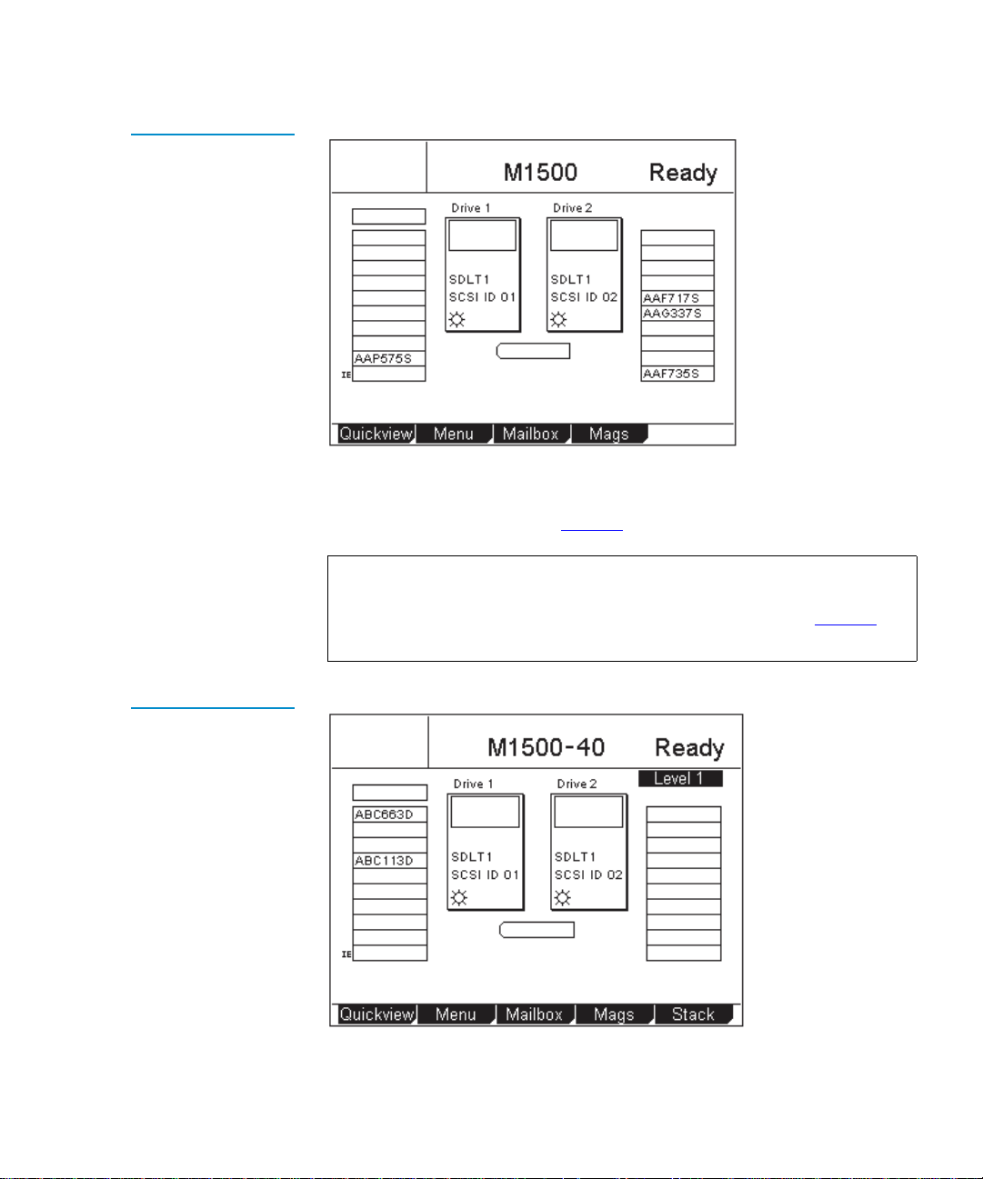
Figure 7 Sample Main
Screen, Stand-alone
M1500
Chapter 2 Basic Operations
Introduction
Tandberg Data
If the library is an M1500 and is part of a multiple library stack, the main
screen displays the level of the M1500 module and provides an additional
button, the
Stack button (see figure 8).
Note: In a multiple library stack, each M1500 library module is
considered one “level” of the library. Each M2500 library
module is considered four levels of the library (see figure 9
).
Levels are numbered from top to bottom, starting with 1.
Figure 8 Sample Main
Screen, M1500 in a
Multiple Library Stack
Tandberg Data
Tandberg Data M-Series User’s Guide 15
Page 32

Chapter 2 Basic Operations
Introduction
If the library is an M2500, the first main screen provides a Level button
and displays information about the top level of the M2500 (see figure 9
and figure 10
M2500, press the
). To view main screens for the other levels within the
Level button.
Figure 9 M2500
Library Levels
Figure 10 Sample
Main Screen, M2500
Right magazinesLeft magazines
Level 1
Level 2
Level 3
Level 4
Tandberg Data
16 Tandberg Data M-Series User’s Guide
Page 33

Chapter 2 Basic Operations
Introduction
GUI Buttons 2 At the bottom of each GUI screen are up to five button labels. These labels
indicate the functions of the five push buttons below the GUI. To select a
function, press the push button directly below the button label on the
GUI screen (see figure 11
Figure 11 Using the
GUI Buttons
To select this
function,
press this
button:
).
Tandberg Data
Button
labels
Push
buttons
GUI Icons 2 Table 4 explains the meaning of each GUI icon.
Table 4 GUI Icons
Icon Meaning
No tape present
Tape loading
Tape unloading
Tape unloaded
Tandberg Data M-Series User’s Guide 17
Page 34

Chapter 2 Basic Operations
Introduction
Icon Meaning
Tape idle
Tape rewinding
Locating data
Reading data
Writing data
Power on
!
Drive fault
Tape is write-protected
Drive needs cleaning
Slot empty
Slot occupied
Slot occupied - no label or bad bar code
1 slot mailbox - NOT SCSI import/export element
1 slot mailbox and SCSI import/export element
18 Tandberg Data M-Series User’s Guide
Page 35

Chapter 2 Basic Operations
Using the Quick View Menu Screen
Using the Quick View Menu Screen 2
The Quick View Menu screen allows you to view information about the
library, drives, and inventory without placing the library in a NOT
READY state.
Note: The Quick View Menu screen allows you to view the current
library configuration only; you cannot make any changes to
the configuration.
Accessing the Quick View Menu Screen
Figure 12 Quick View
Menu Screen
To access the Quick View Menu screen, press Quickview on the main
screen. The GUI displays the
Quick View Menu screen (see figure 12).
2
Tandberg Data
Tandberg Data M-Series User’s Guide 19
Page 36

Chapter 2 Basic Operations
Using the Quick View Menu Screen
Viewing Library Information
Figure 13 Sample
Library Information
Screen
To view library information using the Quick View Menu screen:
2
1 Access the Quick View Menu screen (see Accessing the Quick View
Menu Screen).
2 Press
Library.
The GUI displays the
Tandberg Data
Library Information screen (see figure 13).
The Library Information screen displays the following information
about the library:
•Model
•Code version
• Boot version
• Serial number
•SCSI board type
• SCSI ID
• SCSI vendor ID
• SCSI product ID
• SCSI product revision
3 When you are finished viewing library information, press
return to the
20 Tandberg Data M-Series User’s Guide
Quick View Menu screen.
Back to
Page 37

Chapter 2 Basic Operations
Using the Quick View Menu Screen
Viewing Tape Drive Information
Figure 14 Sample
Drive Information
Screen
To view tape drive information using the Quick View Menu screen:
2
1 Access the
Quick View Menu screen (see Accessing the Quick View
Menu Screen).
2 Press
Drive.
The GUI displays the
Tandberg Data
Drive Information screen (see figure 14).
The Drive Information screen displays the following information
about each drive installed in the library module:
• Drive type
• SCSI ID
• Serial number
• Code revision
Note: If the library is an M2500, this screen displays a
button. Pressing this button displays drive information for
each library level within the M2500.
3 When you are finished viewing drive information, press
return to the
Tandberg Data M-Series User’s Guide 21
Quick View Menu screen.
Level
Back to
Page 38

Chapter 2 Basic Operations
Using the Quick View Menu Screen
Viewing Inventory Information
Figure 15 Sample
Inventory Screen
To view inventory information using the Quick View Menu screen:
2
1 Access the
Quick View Menu screen (see Accessing the Quick View
Menu Screen on page 19).
2 Press
Inventory.
The GUI displays the
Tandberg Data
Inventory screen (see figure 15).
The Inventory screen provides a graphical representation of the
library inventory.
Note: If the library is an M1500 in a multiple library stack or an
M2500, this screen displays a
button displays inventory information for other library
levels.
3 When you are finished viewing inventory information, press
return to the
22 Tandberg Data M-Series User’s Guide
Quick View Menu screen.
Level button. Pressing this
Back to
Page 39
Chapter 2 Basic Operations
Using the Quick View Menu Screen
Turning Drive Power On or Off (Quick View Menu Screen)
Figure 16 Sample
Tape Drive Power
Screen
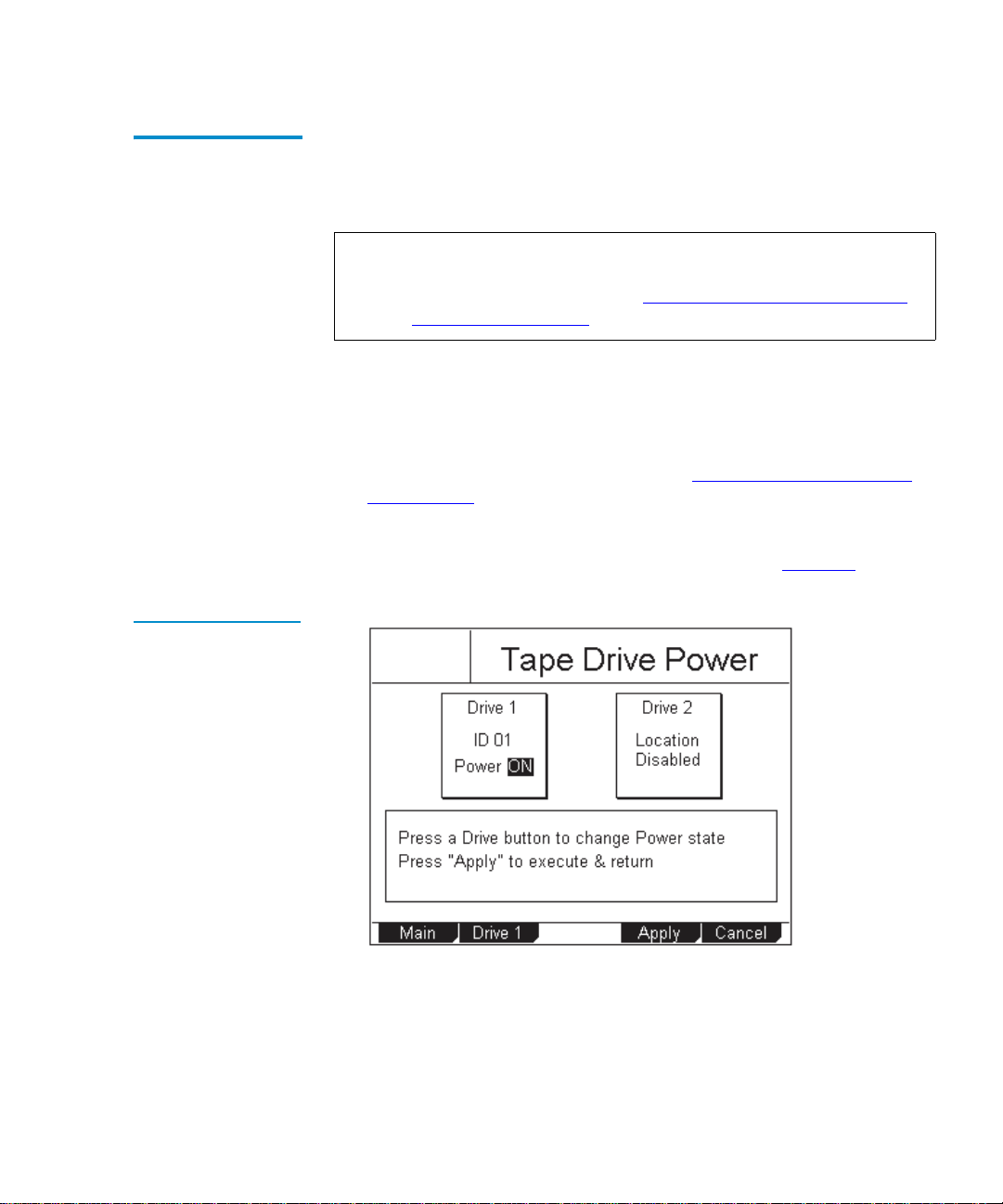
The Drive Power option allows you to turn drive power on or off from the
GUI. Use this option to turn off drive power when you are hot-swapping
a tape drive.
2
Note: This option is available on both the
and the
Maintenance screen, refer to Turning Drive Power On or Off
Maintenance screen. To access this option on the
(Maintenance Screen) on page 71.
Turning Drive Power On or Off in an M1500 Library
To turn drive power on or off in an M1500 library:
1 Access the
Quick View Menu screen (see Accessing the Quick View
Menu Screen on page 19).
2 Press
Drv Pwr.
The GUI displays the
Tandberg Data
Tape Drive Power screen (see figure 16).
Quick View Menu screen
2
3 Press the button that corresponds to the drive you wish to power on
or off:
Drive 1 or Drive 2.
The GUI displays the currently selected setting in the tape drive box
at the top of the screen.
Tandberg Data M-Series User’s Guide 23
Page 40

Chapter 2 Basic Operations
Using the Quick View Menu Screen
4 Press Apply to save the change and return to the Quick View Menu
screen.
Figure 17 Sample
Drive Power Screen
To return to the
state of the drive, press
Quick View Menu screen without changing the power
Cancel.
Turning Drive Power On or Off in an M2500 Library
To turn drive power on or off in an M2500 library:
1 Access the
Quick View Menu screen (see Accessing the Quick View
Menu Screen on page 19).
2 Press
Drv Pwr.
The GUI displays the
Tandberg Data
Drive Power screen (see figure 17).
2
3 Press the Up or Down buttons to highlight the drive you wish to
power on or off.
4 Press
Select.
The drive power setting is highlighted.
5 Press the
24 Tandberg Data M-Series User’s Guide
Up or Down buttons to change the current setting.
Page 41
Chapter 2 Basic Operations
Moving Tape Cartridges
6 When the desired setting is displayed, press Select.
To exit this screen without changing the drive power setting, press
Cancel.
7 Press
Back to save the change and return to the Quick View Menu
screen.
Moving Tape Cartridges 2
To move tape cartridges within the library:
Figure 18 Menu
Screen
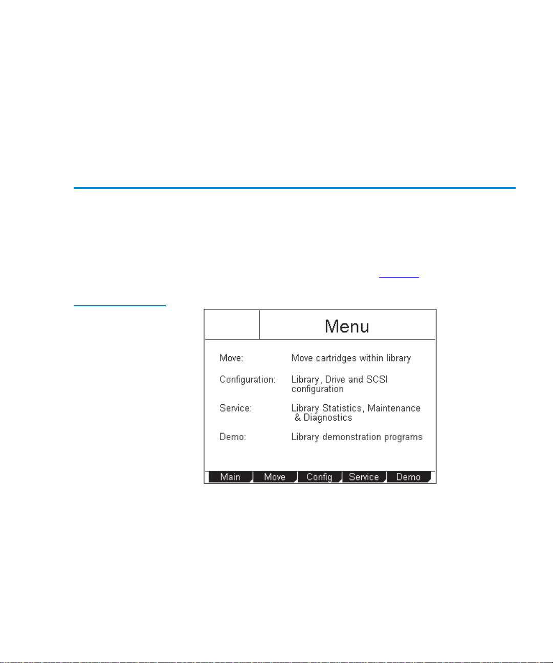
1 On the main screen, press
The GUI displays the
Tandberg Data
Menu.
Menu screen (see figure 18).
2 Press Move.
Tandberg Data M-Series User’s Guide 25
Page 42
Chapter 2 Basic Operations
Moving Tape Cartridges
Figure 19 Sample
Move Cartridge FROM
Screen
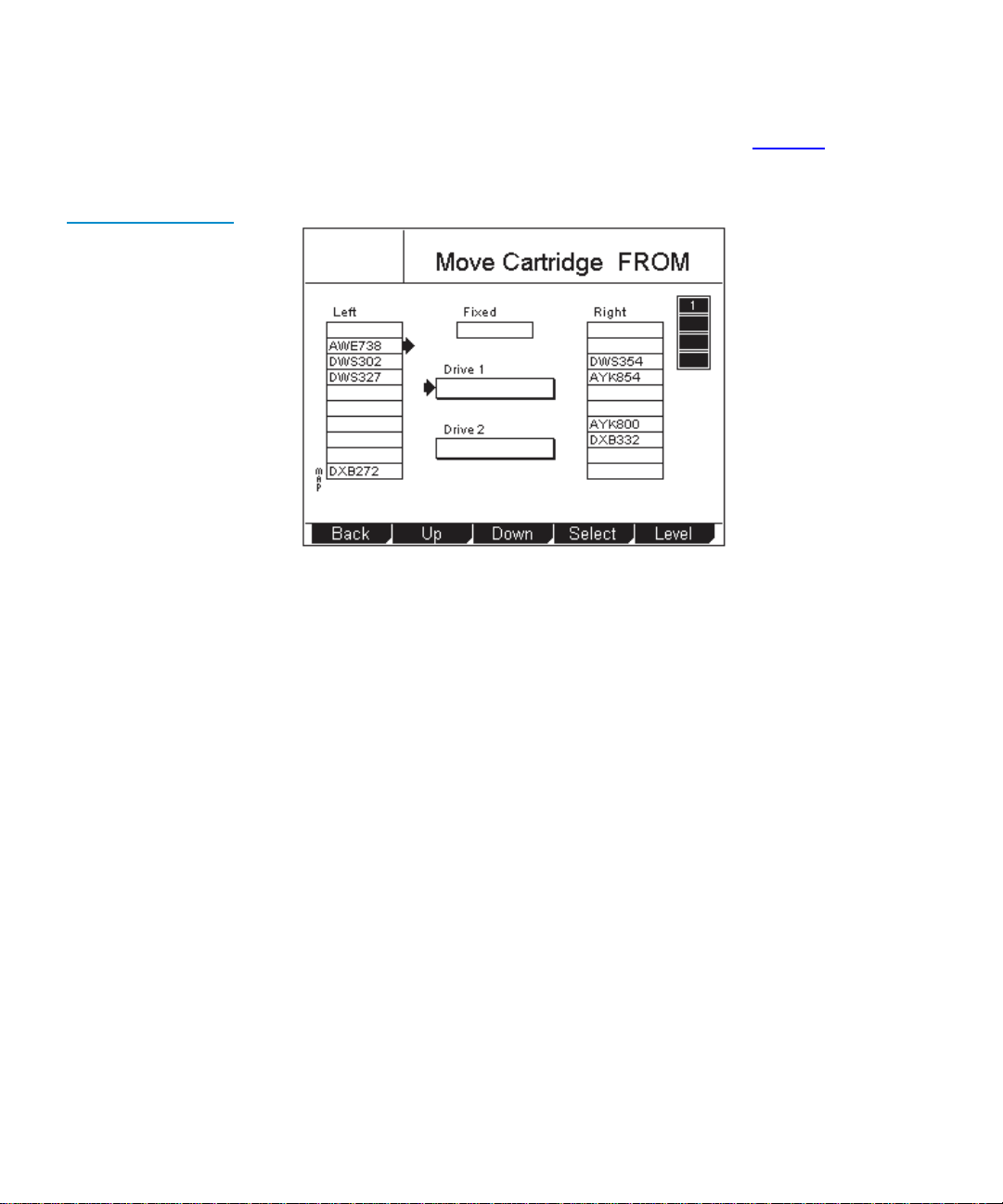
The GUI displays the Move Cartridge FROM screen (see figure 19). A
flashing arrow indicates the currently selected source element.
Tandberg Data
3 If the library is an M1500 in a multiple library stack or an M2500,
press the
Level button to select the level where the desired source
element is located.
4 Press the
Up and Down buttons to select the source element of the
cartridge.
5 When the flashing arrow is next to the desired source element, press
Select.
26 Tandberg Data M-Series User’s Guide
Page 43
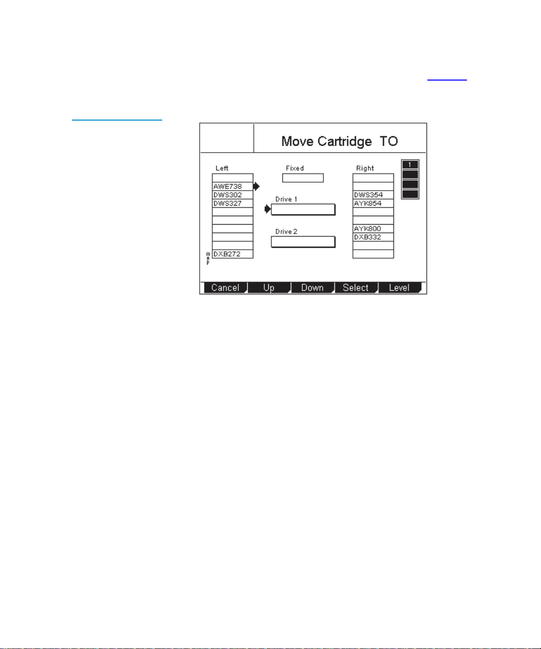
Figure 20 Sample
Move Cartridge TO
Screen
Chapter 2 Basic Operations
Moving Tape Cartridges
The GUI displays the Move Cartridge TO screen (see figure 20). A
flashing arrow indicates the currently selected destination element.
Tandberg Data
6 If the library is an M1500 in a multiple library stack or an M2500,
press the
Level button to select the level where the desired
destination element is located.
7 Press the
Up and Down buttons to select the destination element.
8 When the flashing arrow is next to the desired destination element,
press
Select.
Tandberg Data M-Series User’s Guide 27
Page 44

Chapter 2 Basic Operations
Using the Mailbox
Figure 21 Sample
Confirm Move
Cartridge Screen
The GUI displays the Confirm Move Cartridge screen (see figure 21).
Tandberg Data
9 Verify that the GUI displays the correct source and destination
elements, then press
Confirm.
To cancel the cartridge move, press
The GUI displays the message
After the cartridge move is complete, the GUI displays the
Cartridge FROM
10 Press
11 Press
Back to return to the Menu screen.
Main to return to the main screen.
screen again.
Cancel.
Moving cartridge... Please wait.
Move
Using the Mailbox 2
Using the Mailbox screen, you can:
• View mailbox status
• Import and export cartridges
• Change the size of the mailbox by changing the setting of the
Export
option
28 Tandberg Data M-Series User’s Guide
Import/
Page 45

Figure 22 Sample
Mailbox Screen
Chapter 2 Basic Operations
Using the Mailbox
To access the Mailbox screen, press Mailbox on the main screen. The GUI
displays the
Tandberg Data
Mailbox screen (see figure 22).
Viewing Mailbox Status
The Mailbox screen displays the following information:
2
• The current setting of the
Import/Export option (see Changing the
Import/Export Setting on page 62 for more information about the
available settings)
• Whether the mailbox is open or closed
• Whether the mailbox is occupied
• The bar code number of the cartridge, if the mailbox is occupied
Note: If the
Import/Export option is set to None, the Mailbox screen
does not display any “Status” or “Tape” information.
If the
Import/Export option is set to 10-Slot (or 12-Slot for
LTO), the
Mailbox screen does not display any “Status:
Occupied” or “Tape” information.
Tandberg Data M-Series User’s Guide 29
Page 46

Chapter 2 Basic Operations
Using the Mailbox
Importing and Exporting Cartridges
The procedure for importing and exporting cartridges varies depending
on the setting of the
2
Export Setting on page 62).
• To import and export cartridges when the
to manual access port (
and Exporting a Cartridge in MAP Mode
• To import and export cartridges when the
to
10-Slot (or 12-Slot in LTO libraries), see Importing Cartridges in
Import/Export option (see Changing the Import/
Import/Export option is set
MAP), see Importing a Cartridge in MAP Mode
.
Import/Export option is set
10-Slot or 12-Slot Mode and Exporting Cartridges in 10-Slot or 12-Slot
Mode.
• To import and export cartridges when the
to
1-Slot, see Importing a Cartridge in 1-Slot Mode and Exporting a
Import/Export option is set
Cartridge in 1-Slot Mode.
Importing a Cartridge in MAP Mode
To import a cartridge in MAP mode:
1 On the main screen, press
The GUI displays the
2 Press
Open.
Mailbox.
Mailbox screen (see figure 22).
2
The GUI displays the
Figure 23 Mailbox OPEN Screen
30 Tandberg Data M-Series User’s Guide
Tandberg Data
Mailbox - OPEN screen (see figure 23).
Page 47

Chapter 2 Basic Operations
Using the Mailbox
3 Press the button next to the top left magazine access door and open
the door.
4 Pull the magazine forward until it stops.
5 Remove the data cartridge (if any) from the mailbox.
6 Insert the cartridge you wish to import into the mailbox.
7 Reinsert the magazine into the library.
8 Close the magazine access door.
9 On the
Mailbox - OPEN screen, press Re-Lock.
The library locks the magazine access door and inventories the
mailbox.
10 Use the
Move command on the Mailbox screen to move the imported
cartridge to another data element.
11 If you removed a data cartridge from the mailbox, replace it:
a Repeat steps 1
b Reinsert the data cartridge you removed in step 5
through 4 to open the mailbox again.
into the
mailbox.
c Reinsert the magazine into the library.
d Close the magazine access door.
e On the
Mailbox screen, press Re-Lock.
The magazine access door locks.
Exporting a Cartridge in MAP Mode
To export a cartridge in MAP mode:
1 If there is currently a data cartridge in the mailbox, remove it:
2
a On the main screen, press
The GUI displays the
b Press
Open.
The GUI displays the
Mailbox.
Mailbox screen (see figure 22).
Mailbox - OPEN screen (see figure 23).
c Press the button next to the top left magazine access door and
open the door.
d Pull the magazine forward until it stops.
Tandberg Data M-Series User’s Guide 31
Page 48

Chapter 2 Basic Operations
Using the Mailbox
e Remove the data cartridge from the mailbox.
f Reinsert the magazine into the library.
g Close the magazine access door.
h On the
Mailbox - OPEN screen, press Re-Lock.
The library locks the magazine access door and inventories the
mailbox.
2 Use the
Move command on the Mailbox screen to move the cartridge
you wish to export to the mailbox.
3 Repeat steps 1
a through 1d to open the mailbox again.
4 Remove the exported cartridge from the mailbox.
5 Reinsert the data cartridge you removed in step 1
e (if any) into the
mailbox.
6 Reinsert the magazine into the library.
7 Close the magazine access door.
8 On the
Mailbox - OPEN screen, press Re-Lock.
The library locks the magazine access door and inventories the
mailbox.
Importing Cartridges in 10-Slot or 12-Slot Mode
To import cartridges in 10-slot or 12-slot mode:
1 On the main screen, press
The GUI displays the
2 Press
Open.
Mailbox.
Mailbox screen (see figure 22).
2
The GUI displays the
Mailbox - OPEN screen (see figure 23).
3 Press the button next to the top left magazine access door and open
the door.
4 Pull the magazine out of the library.
5 Insert the cartridges you wish to import into the magazine.
6 Reinsert the magazine into the library.
32 Tandberg Data M-Series User’s Guide
Page 49

7 Close the magazine access door.
Chapter 2 Basic Operations
Using the Mailbox
8 On the
Mailbox - OPEN screen, press Re-Lock.
The library locks the magazine access door and the cartridges are
moved under control of the host software to the desired locations.
Exporting Cartridges in 10-Slot or 12-Slot Mode
To export cartridges in 10-slot or 12-slot mode:
1 Use the backup software to export cartridges to the top left magazine.
2 On the main screen, press
The GUI displays the
3 Press
Open.
The GUI displays the
Mailbox.
Mailbox screen (see figure 22).
Mailbox - OPEN screen (see figure 23).
4 Press the button next to the top left magazine access door and open
the door.
5 Pull the magazine out of the library.
6 Remove the cartridges from the magazine.
7 Reinsert the magazine into the library.
8 Close the magazine access door.
2
9 On the
Mailbox - OPEN screen, press Re-Lock.
The library locks the magazine access door.
Importing a Cartridge in 1-Slot Mode
To import a cartridge in 1-slot mode:
1 On the main screen, press
The GUI displays the
2 Press
Open.
The GUI displays the
Mailbox.
Mailbox screen (see figure 22).
Mailbox - OPEN screen (see figure 23).
3 Press the button next to the top left magazine access door and open
the door.
Tandberg Data M-Series User’s Guide 33
2
Page 50

Chapter 2 Basic Operations
Using the Mailbox
4 Pull the magazine forward until it stops.
5 Insert the cartridge you wish to import into the mailbox.
6 Reinsert the magazine into the library.
7 Close the magazine access door.
8 On the
Mailbox - OPEN screen, press Re-Lock.
The library locks the magazine access door and the cartridge is
moved under control of the host software to the desired location.
Exporting a Cartridge in 1-Slot Mode
To export a cartridge in 1-slot mode:
1 Use the backup software to export cartridges to the first slot of the top
left magazine.
2 On the main screen, press
The GUI displays the
3 Press
Open.
The GUI displays the
Mailbox.
Mailbox screen (see figure 22).
Mailbox - OPEN screen (see figure 23).
4 Press the button next to the top left magazine access door and open
the door.
5 Pull the magazine forward until it stops.
6 Remove the exported cartridge from the magazine.
7 Reinsert the magazine into the library.
2
8 Close the magazine access door.
9 On the
Mailbox - OPEN screen, press Re-Lock.
The library locks the magazine access door.
34 Tandberg Data M-Series User’s Guide
Page 51

Chapter 2 Basic Operations
Removing the Magazines
Configuring the Mailbox
By default, the Import/Export option is set to MAP. To change this setting:
2
1 On the main screen, press
The GUI displays the
2 On the
Mailbox screen, press Config.
The GUI displays the
Mailbox.
Mailbox screen (see figure 22).
Configuration screen, with the Import/Export
option highlighted.
3 Use the
setting. The available settings are
LTO libraries), and
Up and Down buttons to select the desired Import/Export
None, 1-Slot, 10-Slot (or 12-Slot in
MAP (default).
Note: For more information about these settings, see Changing
the Import/Export Setting on page 62.
4 Press
5 Press
Select.
Main to return to the main screen.
Note: This setting takes effect when you reboot the library.
Removing the Magazines 2
To remove a magazine from an M1500 library, see Removing a Magazine
from an M1500.
To remove a magazine from an M2500 library, see Removing a Magazine
from an M2500.
Tandberg Data M-Series User’s Guide 35
Page 52

Chapter 2 Basic Operations
Removing the Magazines
Removing a Magazine from an M1500
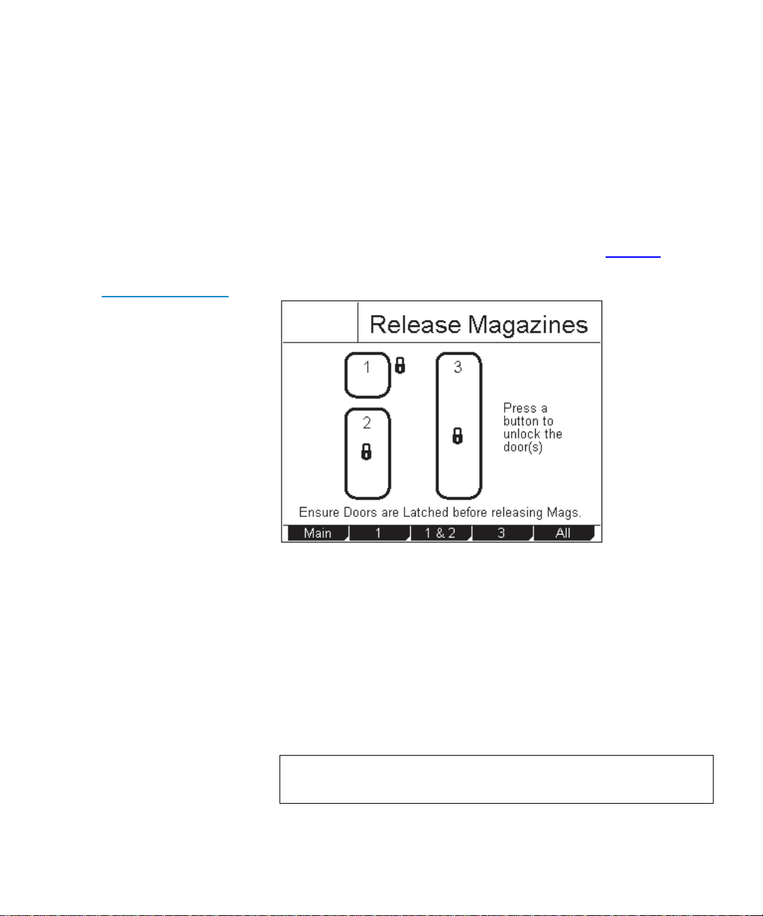
Figure 24 Sample
Release Magazines
Screen
The method for removing the magazines differs depending on whether
the M1500 library is powered up or down:
2
• To remove a magazine from the M1500 library when it is powered
up, see Removing a Magazine when the M1500 Library is
Powered Up.
• To remove a magazine from the M1500 library when it is powered
down, see Removing a Magazine when the M1500 Library is
Powered Down.
Removing a Magazine when the M1500 Library is Powered Up
The magazines are locked in place during normal library operation. To
remove one of these magazines, you must first release the magazine
using the GUI.
To remove the left or right magazine when the M1500 library is
powered up:
1 On the main screen, press
The GUI displays the
Tandberg Data
Mags.
Release Magazines screen (see figure 24).
2
36 Tandberg Data M-Series User’s Guide
Page 53

Chapter 2 Basic Operations
Removing the Magazines
2 Press the button corresponding to the magazine you want to release:
• To release both magazines, press
• To release the left magazine, press
• To release the right magazine, press
Both.
Left.
Right.
The GUI indicates that the magazine or magazines have been
released.
3 Press the button next to the desired magazine access door and open
the door.
4 Grasp the handle at the front of the magazine and pull it forward and
out of the library.
5 When you are finished adding or removing cartridges from the
magazine, replace it in the library and close the magazine door.
6 On the
Release Magazines screen, press Re-Lock.
The library locks the magazine access doors and inventories the
magazines. When the inventory is complete, the GUI displays the
main screen.
Removing a Magazine when the M1500 Library is Powered Down
To remove a magazine when the library is powered down:
2
1 Look through the viewing window and verify that all cartridges are
fully seated either in a magazine slot or in the robotic hand.
Caution: You can damage the library severely if you try to
remove a magazine when one of the data cartridges is
not fully seated.
2 Press the button next to the magazine access door.
The magazine access door opens.
Tandberg Data M-Series User’s Guide 37
Page 54

Chapter 2 Basic Operations
Removing the Magazines
Figure 25 Magazine
Release Button
3 To remove the left magazine:
a Using a slender object such as a pen, press and hold the magazine
release button (see figure 25
).
b Grasp the handle at the front of the left magazine and slide it
forward and out of the library.
Magazine
release
button
4 To remove the right magazine, grasp the handle at the front of the
magazine and slide it forward and out of the library.
Removing a Magazine from an M2500
The method for removing the magazines differs depending on whether
the M2500 library is powered up or down:
2
• To remove a magazine from the M2500 library when it is powered
up, see Removing a Magazine when the M2500 Library is
Powered Up.
• To remove a magazine from the M2500 library when it is powered
down, see Removing a Magazine when the M2500 Library is
Powered Down.
38 Tandberg Data M-Series User’s Guide
Page 55
Chapter 2 Basic Operations
Removing the Magazines
Removing a Magazine when the M2500 Library is Powered Up 2
The magazines are locked in place during normal library operation. To
remove one of these magazines, you must first release the magazine
using the GUI.
To remove a magazine when the library is powered up:
Figure 26 Release
Magazines Screen
1 On the main screen, press
The GUI displays the
Tandberg Data
Mags.
Release Magazines screen (see figure 26).
2 Press the button corresponding to the magazine access door you
want to open:
• To release the top left magazine access door, press
1.
• To release both left magazine access doors, press
• To release the right magazine access door, press
• To release all the magazine access doors, press
1&2.
3.
All.
3 Press the button next to the desired magazine access door and open
the door.
Note: If you are opening the bottom left magazine access door,
open the top left magazine access door first.
Tandberg Data M-Series User’s Guide 39
Page 56

Chapter 2 Basic Operations
Removing the Magazines
4 Grasp the handle at the front of the desired magazine and pull it
forward and out of the library.
5 When you are finished adding or removing cartridges from the
magazine, replace it in the library and close the magazine access
door.
6 On the
Release Magazines screen, press Re-Lock.
The library locks the magazine access doors and inventories the
magazines. When the inventory is complete, the GUI displays the
main screen.
Removing a Magazine when the M2500 Library is Powered Down
To remove a magazine when the library is powered down:
1 Look through the viewing window and verify that all cartridges are
fully seated either in a magazine slot or in the robotic hand.
Caution: You can damage the library severely if you try to
remove a magazine when one of the data cartridges is
not fully seated.
2 To remove the level 1 left magazine:
a Press the button next to the top left magazine access door and
open the door.
b Grasp the handle at the front of the level 1 left magazine and pull
it forward until it stops.
2
Note: If the
Import/Export option is set to 1-Slot or MAP, you will
only be able to pull out the top left magazine far enough to
access the first magazine slot.
If the
Import/Export option is set to None or 10-Slot (12-Slot
for LTO libraries) you will be able to pull the top left
magazine all the way out of the library.
c If the magazine stops after the first slot, perform steps 2
2
h to remove it.
40 Tandberg Data M-Series User’s Guide
d through
Page 57

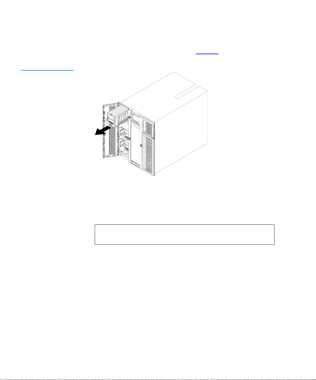
Figure 27 Removing
the Level 2 Left
Magazine
Chapter 2 Basic Operations
Removing the Magazines
d Press the button next to the bottom left magazine access door and
open the door.
e Remove the level 2 left magazine (see figure 27
).
Figure 28 Release
Latch
f Reach into the library underneath the level 1 left magazine and
pull down on the release latch (see figure 28
Release latch
Tandberg Data M-Series User’s Guide 41
).
Page 58
Chapter 2 Basic Operations
Removing the Magazines
Figure 29 Removing
the Level 1 Left
Magazine
g While holding the release latch, pull the level 1 left magazine
forward and out of the library (see figure 29
).
h Reinsert the level 2 left magazine into the library and close the
bottom left magazine access door.
3 To remove any other magazine:
a Press the button next to the desired magazine access door.
Note: If you are opening the bottom left magazine access door,
open the top left magazine access door first.
The magazine access door opens.
b Grasp the handle at the front of the desired magazine and slide it
forward and out of the library.
42 Tandberg Data M-Series User’s Guide
Page 59
Chapter 2 Basic Operations
Viewing Statistics
Viewing Statistics 2
This section explains how to view library, drive, and SCSI statistics using
the
Statistics Menu screen.
Accessing the Statistics Menu Screen
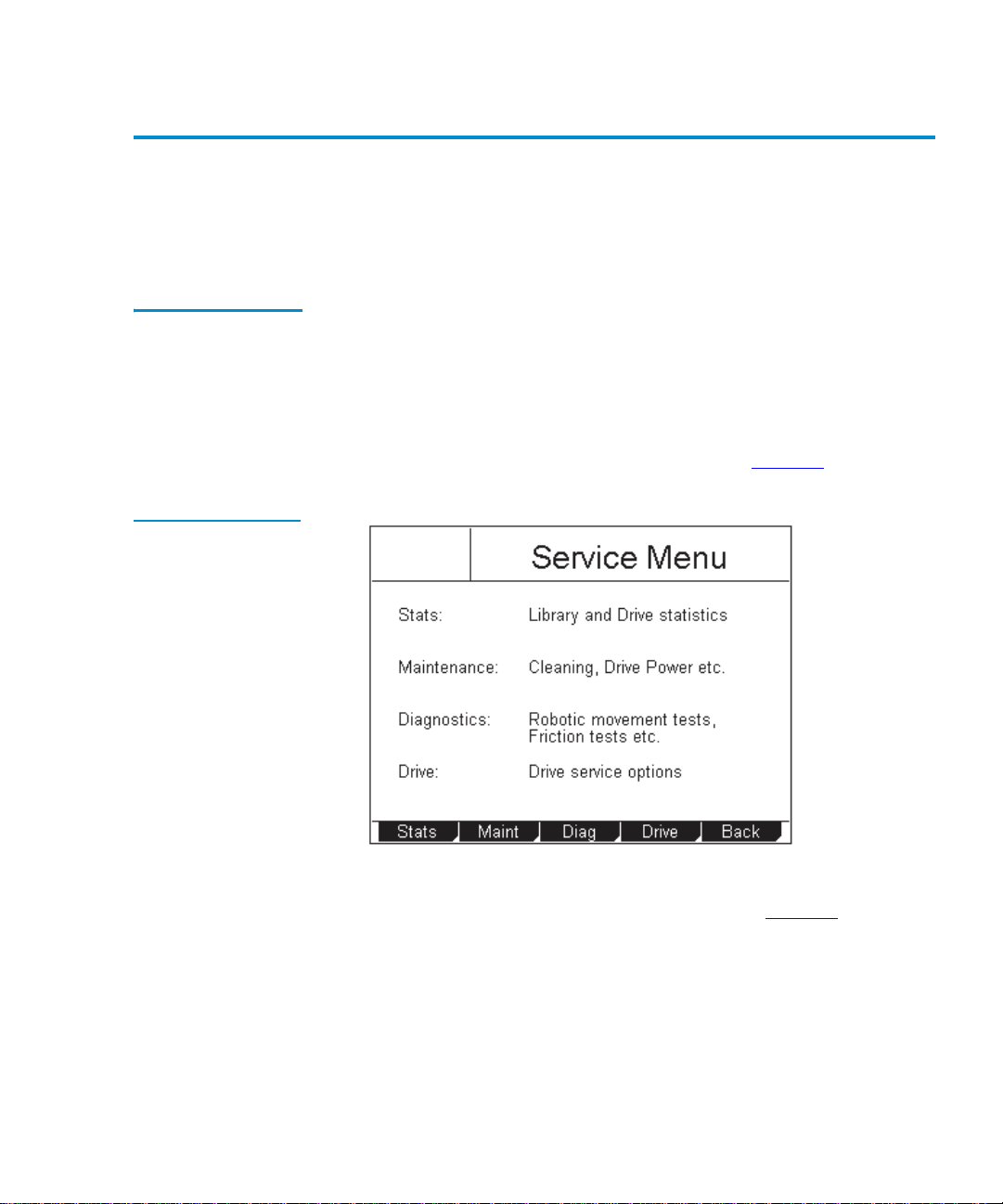
Figure 30 Service
Menu Screen
To access the Statistics Menu screen:
1 On the main screen, press
2
The GUI displays the
2 Press
Service.
The GUI displays the
Tandberg Data
Menu.
Menu screen.
Service Menu screen (see figure 30).
3 Press Stats.
The GUI displays the
Tandberg Data M-Series User’s Guide 43
Statistics Menu screen (see figure 31).
Page 60

Chapter 2 Basic Operations
Viewing Statistics
Figure 31 Statistics
Menu Screen
Tandberg Data
Viewing Library Statistics
Figure 32 Sample
Library Statistics
Screen
To view library statistics:
2
1 Access the
Statistics Menu screen (see Accessing the Statistics Menu
Screen).
2 On the
Statistics Menu screen, press Library.
The GUI displays the
Tandberg Data
Library Statistics screen (see figure 32).
44 Tandberg Data M-Series User’s Guide
Page 61

Chapter 2 Basic Operations
This screen lists the following library statistics:
• Power On Hours
• Slot Fetches Good
• Slot Fetches Bad
• Slot Stows Good
•Slot Stows Bad
• Barcode Retries
• Magazine Inserts
•X Axis Distance
•Y Axis Distance
•Z Axis Distance
•Theta Distance
•Picker Distance
•Elevator Distance
Viewing Statistics
Viewing Dri ve Statistics
3 Press the
Up and Down buttons to scroll through the list.
4 When you have finished viewing the library statistics, press
return to the
Statistics Menu screen, or press Main to return to the
main screen.
To view drive statistics:
2
1 Access the
Statistics Menu screen (see Accessing the Statistics Menu
Screen).
2 On the
The GUI displays the
Statistics Menu screen, press Drive.
Drive Statistics screen (see figure 33).
Tandberg Data M-Series User’s Guide 45
Back to
Page 62
Chapter 2 Basic Operations
Viewing Statistics
Figure 33 Sample
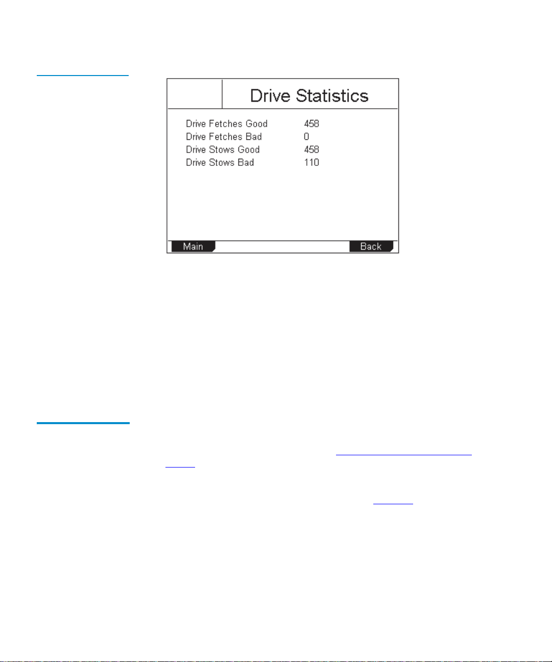
Drive Statistics Screen
Tandberg Data
This screen lists the following drive statistics:
• Drive Fetches Good
•Drive Fetches Bad
Viewing the SCSI History
• Drive Stows Good
•Drive Stows Bad
3 When you have finished viewing the drive statistics, press
return to the
Statistics Menu screen, or press Main to return to the
main screen.
To view a list of the SCSI commands run on the library:
2
1 Access the
Statistics Menu screen (see Accessing the Statistics Menu
Screen).
2 On the
The GUI displays the
Statistics Menu screen, press SCSI.
SCSI History screen (see figure 34).
Back to
46 Tandberg Data M-Series User’s Guide
Page 63
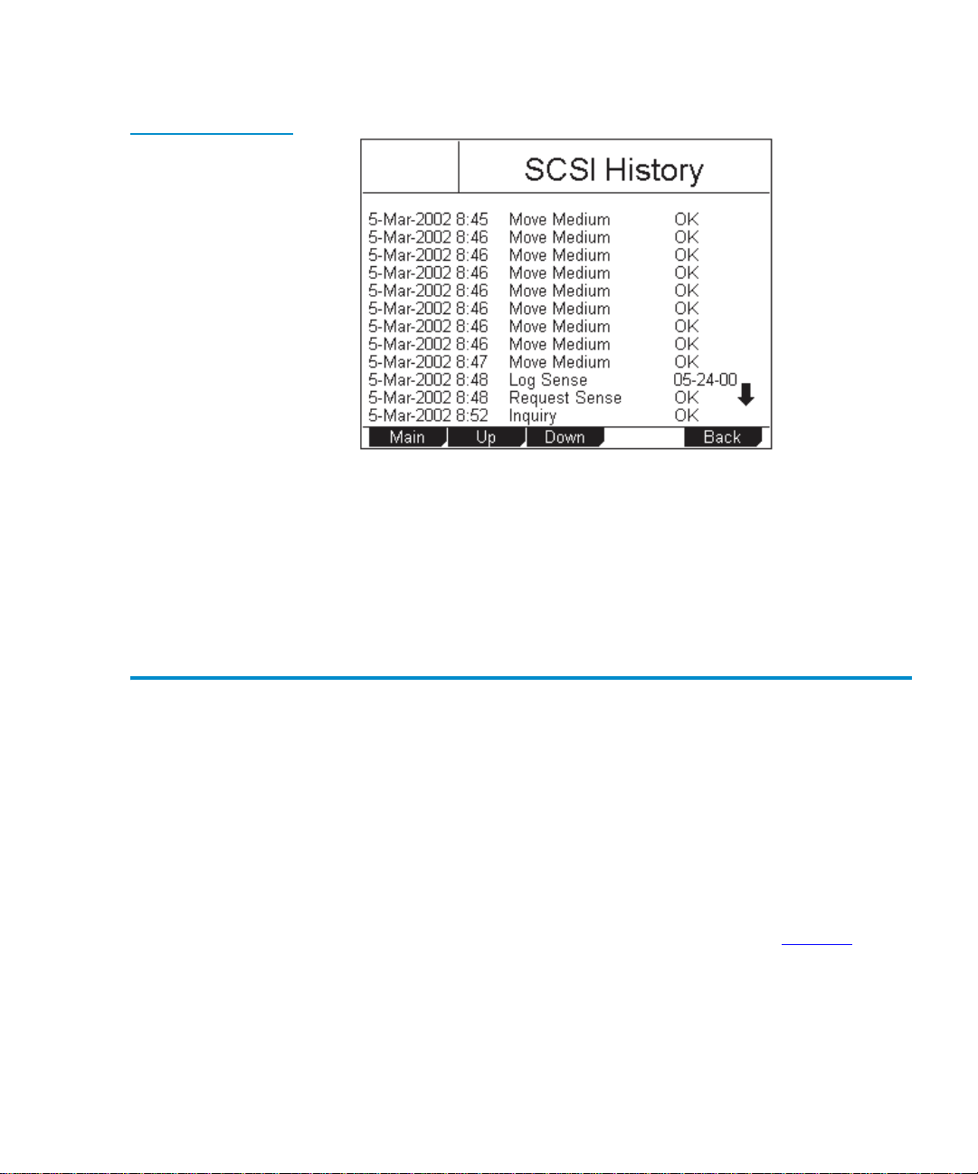
Figure 34 Sample
SCSI History Screen
Chapter 2 Basic Operations
Viewing the Stack Configuration
Tandberg Data
This screen lists SCSI commands by date and time.
3 Press the
4 When you have finished viewing the SCSI history, press
return to the
Up and Down buttons to scroll through the list.
Back to
Statistics Menu screen, or press Main to return to the
main screen.
Viewing the Stack Configuration 2
If the library module is part of a multiple library stack, you can view the
configuration of the entire stack using the
To access the
• On an M1500 library, press
• On an M2500 library, press
Stack Configuration screen:
Stack on the main screen.
Level on the main screen until the Stack
button appears at the lower right corner of the screen. Press
The GUI displays the
Stack Configuration screen (see figure 35).
Stack Configuration screen.
Stack.
Tandberg Data M-Series User’s Guide 47
Page 64

Chapter 2 Basic Operations
Viewing the Stack Configuration
Figure 35 Sample
Stack Configuration
Tandberg Data
Screen
Stack levels
installed
Available stack
levels
= Drive installed
= Drive not installed
= Drive disabled
= Magazine installed
= Magazine not installed
This screen displays the:
• Maximum size of the library (this depends on the length of the
StackLink installed)
• Number of library modules installed in the stack
• Number, location, and SCSI IDs of the tape drives installed
• Number and location of the tape cartridge magazines installed
When you are finished viewing the
Stack Configuration screen, press Main
to return to the main screen.
48 Tandberg Data M-Series User’s Guide
Page 65

Chapter 3
Changing the Library Configuration 3
This chapter explains how to change the library configuration using the
GUI
Configuration screen.
Accessing the Configuration Screen 3
To access the Configuration screen:
1 On the main screen, press
The GUI displays the
Tandberg Data M-Series User’s Guide 49
Menu.
Menu screen (see figure 36).
Page 66
Chapter 3 Changing the Library Configuration
Accessing the Configuration Screen
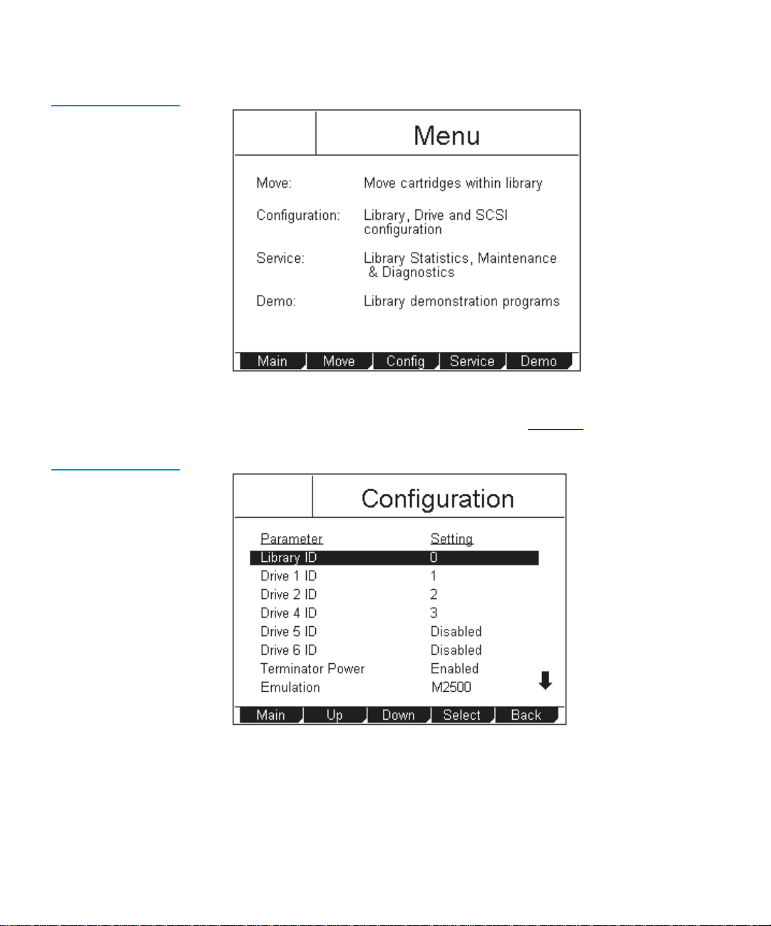
Figure 36 Menu
Screen
Tandberg Data
2 Press Config.
Figure 37
Configuration Screen
The GUI displays the
Tandberg Data
Configuration screen (see figure 37).
50 Tandberg Data M-Series User’s Guide
Page 67

Chapter 3 Changing the Library Configuration
Setting the Library ID
Setting the Library ID 3
By default the library SCSI ID is set to 0. To change the library SCSI ID
setting:
1 Access the
Screen).
2 Press the
3 Press
4 Use the
settings are
5 Press
To return to the
setting, press
6 Press
Note: This setting takes effect when you reboot the library.
Configuration screen (see Accessing the Configuration
Up or Down buttons until Library ID is highlighted.
Select.
Up or Down buttons to select the desired SCSI ID. Available
0 through 15.
Select.
Configuration screen without changing the option
Cancel.
Main to return to the main screen.
Changing a Tape Drive ID 3
By default, the M1500 tape drive SCSI IDs are set as follows:
• Drive 1 ID = 1
• Drive 2 ID = 2
By default, the M2500 tape drive SCSI IDs are set as follows:
• Drive 1 ID = 1
• Drive 2 ID = 2
• Drive 3 ID = 3
• Drive 4 ID = 4
• Drive 5 ID = 15
• Drive 6 ID = 14
Tandberg Data M-Series User’s Guide 51
Page 68

Chapter 3 Changing the Library Configuration
Changing a Tape Drive ID
Figure 38 illustrates the drive numbering scheme for the M2500.
Figure 38 M2500
Drive Numbering
To change a tape drive SCSI ID:
1 Access the
Configuration screen (see Accessing the Configuration
Screen).
Drive 1 (default
SCSI ID = 1)
Drive 2 (default
SCSI ID = 2)
Drive 3 (default
SCSI ID = 3)
Drive 4 (default
SCSI ID = 4)
Drive 5 (default
SCSI ID = 15)
Drive 6 (default
SCSI ID = 14)
2 Press the
Up or Down buttons until the desired drive ID (for example,
Drive 1 ID) is highlighted.
3 Press
4 Use the
Select.
Up or Down buttons to select the desired SCSI ID. Available
settings are
0 through 9, A through F, and Disabled.
Caution: Set the drive SCSI ID to
installed in the library.
52 Tandberg Data M-Series User’s Guide
Disabled only if the drive is not
Page 69

5 Press Select.
Chapter 3 Changing the Library Configuration
Changing the Terminator Power Setting
To return to the
setting, press
6 If desired, repeat steps 2
Configuration screen without changing the option
Cancel.
through 5 to set the SCSI ID for another tape
drive.
7 Press
Main to return to the main screen.
Note: This setting takes effect when you reboot the library.
Changing the Terminator Power Setting 3
The T erminator Power option controls whether the library robotics
provide terminator power.
To enable or disable robotics terminator power:
1 Access the
Screen).
2 Press the
3 Press
Configuration screen (see Accessing the Configuration
Up or Down buttons until Terminator Power is highlighted.
Select.
4 Use the
setting. Available settings are
5 Press
To return to the
setting, press
6 Press
Up or Down buttons to select the desired Terminator Power
Enabled (default) and Disabled.
Select.
Configuration screen without changing the option
Cancel.
Main to return to the main screen.
Note: This setting takes effect when you reboot the library.
Tandberg Data M-Series User’s Guide 53
Page 70

Chapter 3 Changing the Library Configuration
Changing the Emulation Setting
Changing the Emulation Setting 3
The Emulation option allows you to set the library to act as either a
Quantum ATL library or an M4 Data library.
To set the emulation:
1 Access the
Screen on page 49).
2 Press the
3 Press
4 Use the
The available settings are
Note: The default setting for the M1500 is
5 Press
To return to the
setting, press
6 Press
Note: This setting takes effect when you reboot the library.
Configuration screen (see Accessing the Configuration
Up or Down buttons until Emulation is highlighted.
Select.
Up or Down buttons to select the desired Emulation setting.
M2500, 1500, and M4 Data.
M4 Data; the default
setting for the M2500 is
Select.
Configuration screen without changing the option
Cancel.
Main to return to the main screen.
M2500.
Changing the Storage Slot Count Setting 3
The Storage Slot Count option controls how many storage elements are
reported to the SCSI host.
Note: When changing this option setting in a multiple library stack,
you must use the GUI on the SCSI master (the library module
connected to the SCSI host) in order for the changes to take
effect.
54 Tandberg Data M-Series User’s Guide
Page 71

Chapter 3 Changing the Library Configuration
Changing the Sync Negotiation Setting
To change the Storage Slot Count setting:
1 Access the
Configuration screen (see Accessing the Configuration
Screen on page 49).
2 Press the
3 Press
4 Use the
Up or Down buttons until Storage Slot Count is highlighted.
Select.
Up or Down buttons to select the desired Storage Slot Count
setting. The available settings are:
•
Default (all storage elements detected by the library are reported
to the SCSI host)
• Any value from 1 through the number of storage elements in the
library (this number varies depending on the library, the tape
drive type, and the setting of the
Import/Export and Auto Clean
options).
5 Press
6 To return to the
7 Press
Select.
Configuration screen without changing the option
setting, press
Main to return to the main screen.
Cancel.
Note: This setting takes effect when you reboot the library.
Changing the Sync Negotiation Setting 3
The Sync Negotiation option controls whether the library robotics
negotiates synchronous data transfer mode. Normally, this negotiation is
performed by the host.
Note: This option does not enable or disable synchronous data
transfers; it only controls the ability of the library to negotiate
for such transfers.
Tandberg Data M-Series User’s Guide 55
Page 72

Chapter 3 Changing the Library Configuration
Changing the Wide Negotiation Setting
To enable or disable Sync Negotiation:
1 Access the
Configuration screen (see Accessing the Configuration
Screen on page 49).
2 Press the
3 Press
4 Use the
setting. The available settings are
5 Press
To return to the
setting, press
6 Press
Up or Down buttons until Sync Negotiation is highlighted.
Select.
Up or Down buttons to select the desired Sync Negotiation
Enabled (default) and Disabled.
Select.
Configuration screen without changing the option
Cancel.
Main to return to the main screen.
Changing the Wide Negotiation Setting 3
The Wide Negotiation option controls whether the library robotics
negotiates wide data transfer mode. Normally, this negotiation is
performed by the host.
Note: This option does not enable or disable wide data transfers; it
only controls the ability of the library to negotiate for such
transfers.
To enable or disable
1 Access the
Wide Negotiation:
Configuration screen (see Accessing the Configuration
Screen on page 49).
2 Press the
3 Press
4 Use the
setting. The available settings are
56 Tandberg Data M-Series User’s Guide
Up or Down buttons until Wide Negotiation is highlighted.
Select.
Up or Down buttons to select the desired Wide Negotiation
Enabled (default) and Disabled.
Page 73

5 Press Select.
Chapter 3 Changing the Library Configuration
Changing the Serialization Setting
To return to the
setting, press
6 Press
Main to return to the main screen.
Configuration screen without changing the option
Cancel.
Changing the Serialization Setting 3
The Serialization option controls how the library returns the tape drive
serial number when a
When
Serialization is set to On, the tape drive serial number is returned in
a format compatible with Prism products. When
the tape drive serial number is returned in a vendor unique format. This
setting is only valid when
the Emulation Setting on page 54).
To enable or disable drive serialization:
1 Access the
Configuration screen (see Accessing the Configuration
Screen on page 49).
2 Press the
3 Press
Up or Down buttons until Serialization is highlighted.
Select.
Read Element Status is requested.
Serialization is set to Off,
Emulation is set to M2500 or 1500 (see Changing
4 Use the
The available settings are
5 Press
To return to the
setting, press
6 Press
Up or Down buttons to select the desired Serialization setting.
Enabled and Disabled (default).
Select.
Configuration screen without changing the option
Cancel.
Main to return to the main screen.
Tandberg Data M-Series User’s Guide 57
Page 74

Chapter 3 Changing the Library Configuration
Changing the Short Labels Setting
Changing the Short Labels Setting 3
The Short Labels option controls how many bar code label characters are
returned when the host issues a
Short Labels is set to:
•
Off, all of the bar code label characters are returned
•
On, only the first six characters of the bar code label are returned
Read Element Status command. When
To enable or disable
1 Access the
Short Labels:
Configuration screen (see Accessing the Configuration
Screen on page 49).
2 Press the
3 Press
4 Use the
The available settings are
5 Press
6 To return to the
setting, press
7 Press
Up or Down buttons until Short Labels is highlighted.
Select.
Up or Down buttons to select the desired Sho rt Labe ls setting.
Enabled and Disabled (default).
Select.
Configuration screen without changing the option
Cancel.
Main to return to the main screen.
Changing the Illumination Setting 3
The Illumination option allows you to turn the interior illumination of the
library on or off. This illumination allows you to view the robotics easily
through the viewing window.
To enable or disable
1 Access the
Illumination:
Configuration screen (see Accessing the Configuration
Screen on page 49).
2 Press the
3 Press
58 Tandberg Data M-Series User’s Guide
Up or Down buttons until Illumination is highlighted.
Select.
Page 75

Chapter 3 Changing the Library Configuration
Changing the Off-Line Time Setting
4 Use the Up or Down buttons to select the desired Illumination setting.
The available settings are
Enabled (default) and Disabled.
5 Press
6 Press
Select.
To return to the
setting, press
Main to return to the main screen.
Configuration screen without changing the option
Cancel.
Changing the Off-Line Time Setting 3
When you access the Menu screen using the GUI, the library becomes
NOT READY and will not respond to any SCSI commands issued. If you
leave the library unattended in menu mode, the library goes back to a
READY state after a pre-set time-out, controlled by the
option. You can set this time-out to any value from 1 to 99 minutes, or
turn it off.
To set the
1 Access the
Off-Line Time:
Configuration screen (see Accessing the Configuration
Screen on page 49).
2 Press the
3 Press
Up or Down buttons until Off-Line Time is highlighted.
Select.
Off-Line Time
4 Use the
The available settings are
5 Press
To return to the
setting, press
6 Press
Up or Down buttons to select the desired Off-Line Time setting.
1 through 99 and Disabled (default).
Select.
Configuration screen without changing the option
Cancel.
Main to return to the main screen.
Tandberg Data M-Series User’s Guide 59
Page 76

Chapter 3 Changing the Library Configuration
Changing the Barcode Scanner Setting
Changing the Barcode Scanner Setting 3
The Barcode Scanner option controls whether the bar code scanner is
enabled or disabled. When the scanner is enabled, the library attempts to
detect a bar code on all tape cartridge labels. If the correct bar code labels
are not used, or if some cartridges are not labeled, scanning time may be
greatly increased. Therefore, it is recommended that you disable the
Barcode Scanner option if you do not intend to use compatible bar code
labels.
To enable or disable the
1 Access the
Screen on page 49).
2 Press the
3 Press
4 Use the
setting. The available settings are
5 Press
To return to the
setting, press
6 Press
Note: This setting takes effect when you reboot the library.
Configuration screen (see Accessing the Configuration
Up or Down buttons until Barcode Scanner is highlighted.
Select.
Up or Down buttons to select the desired Barcode Scanner
Select.
Main to return to the main screen.
Barcode Scanner option:
Enabled (default) and Disabled.
Configuration screen without changing the option
Cancel.
Changing the Baud Rate Setting 3
The Baud Rate option controls the baud rate setting of the serial
diagnostics port. You can set the baud rate to any standard rate between
1200 baud and 38400 baud.
To set the
1 Access the
60 Tandberg Data M-Series User’s Guide
Baud Rate:
Configuration screen (see Accessing the Configuration
Screen on page 49).
Page 77

Chapter 3 Changing the Library Configuration
Setting the Time
2 Press the Up or Down buttons until Baud Rate is highlighted.
3 Press
4 Use the
5 Press
6 Press
Select.
Up or Down buttons to select the desired Baud Rate setting.
The available settings are
Select.
To return to the
setting, press
Main to return to the main screen.
Configuration screen without changing the option
Cancel.
38400, 19200, 9600, 4800, 2400, and 1200.
Setting the Time 3
To set the time:
1 Access the
Screen on page 49).
2 Press the
3 Press
The hour setting is highlighted.
Configuration screen (see Accessing the Configuration
Up or Down buttons until Time is highlighted.
Select.
4 Use the
5 Press
Up or Down buttons to select the correct hour setting.
Select.
The minute setting is highlighted.
6 Use the
7 Press
Up or Down buttons to select the correct minute setting.
Select.
The seconds setting is highlighted.
8 Use the
9 Press
10 Press
Up or Down buttons to select the correct seconds setting.
Select.
Main to return to the main screen.
Tandberg Data M-Series User’s Guide 61
Page 78

Chapter 3 Changing the Library Configuration
Setting the Date
Setting the Date 3
To set the date:
1 Access the
Screen on page 49).
2 Press the
3 Press
The day setting is highlighted.
4 Use the
5 Press
The month setting is highlighted.
6 Use the
7 Press
The year setting is highlighted.
8 Use the
9 Press
10 Press
Configuration screen (see Accessing the Configuration
Up or Down buttons until Date is highlighted.
Select.
Up or Down buttons to select the correct day of the month.
Select.
Up or Down buttons to select the correct month.
Select.
Up or Down buttons to select the correct year.
Select.
Main to return to the main screen.
Changing the Import/Export Setting 3
The Import/Export option controls whether the host recognizes the slots of
the top left magazine as import/export elements or as storage elements:
• Import/export elements are used to move cartridges in and out of the
library under host control. Because these elements are used
exclusively for importing and exporting cartridges, they are left
empty during normal library operation, reducing the storage capacity
of the library.
• Storage elements are used to store data cartridges. Using storage
elements to import and export cartridges can be risky since these
operations are not controlled by the host.
62 Tandberg Data M-Series User’s Guide
Page 79
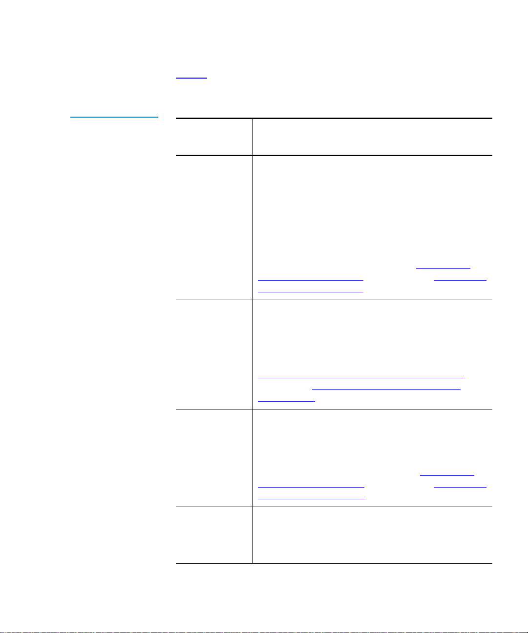
Chapter 3 Changing the Library Configuration
Changing the Import/Export Setting
Table 5 describes each of the possible settings for the Import/Export
option.
T able 5 Import/Export
Settings
Import/Export
Setting Description
MAP
When manual access port (MAP) is selected, you can
use the first slot in the top left magazine to import
and export cartridges from the library. The host
views the MAP as a storage element; therefore, after
using the MAP to import a cartridge, you must
replace the data cartridge that was originally stored
there.
For information about importing and exporting
cartridges when
Cartridge in MAP Mode on page 30 and Exporting a
Cartridge in MAP Mode on page 31.
10-Slot (or
12-Slot in LTO
libraries)
When this setting is selected, all slots in the top left
magazine are configured as import/export elements.
They cannot be used for storage.
For more information about importing and exporting
cartridges when
Importing Cartridges in 10-Slot or 12-Slot Mode
page 32 and Exporting Cartridges in 10-Slot or
12-Slot Mode on page 33.
MAP is selected, see Importing a
10-Slot (or 12-Slot) is selected, see
on
1-Slot
When this setting is selected, the first slot in the top
left magazine is configured as an import/export
element. It cannot be used for storage.
For more information about importing and exporting
cartridges when
1-Slot is selected, see Importing a
Cartridge in 1-Slot Mode on page 33 and Exporting a
Cartridge in 1-Slot Mode on page 34.
None
When this setting is selected, the top left magazine is
used as a 10- or 12-cartridge storage element and
behaves in exactly the same way as the other
magazines.
Tandberg Data M-Series User’s Guide 63
Page 80

Chapter 3 Changing the Library Configuration
Changing the Auto-Clean Setting
To select the Import/Export setting:
Caution: Changing this setting may cause the host(s) to fail to
recognize the library. If you change this setting, be aware
that you will have to reconfigure your backup software for
the new library configuration.
1 Access the
Configuration screen (see Accessing the Configuration
Screen on page 49).
2 Press the
3 Press
4 Use the
The available settings are
libraries), and
5 Press
To return to the
setting, press
6 Press
Up or Down buttons until Import/Export is highlighted.
Select.
Up or Down buttons to select the desired Import/Export setting.
None, 1-Slot, 10-Slot (or 12-Slot in LTO
MAP (default).
Select.
Configuration screen without changing the option
Cancel.
Main to return to the main screen.
Note: This setting takes effect when you reboot the library.
Changing the Auto-Clean Setting 3
To enable or disable Auto-Clean:
1 Access the
Configuration screen (see Accessing the Configuration
Screen on page 49).
2 Press the
3 Press
4 Use the
The available settings are
5 Press
64 Tandberg Data M-Series User’s Guide
Up or Down buttons until Auto-Clean is highlighted.
Select.
Up or Down buttons to select the desired Auto-Clean setting.
Enabled or Disabled (default).
Select.
Page 81

Chapter 3 Changing the Library Configuration
Changing the Ignore Host Lock Setting
To return to the Configuration screen without changing the option
setting, press
Cancel.
6 Press
Main to return to the main screen.
Note: This setting takes effect when you reboot the library.
Changing the Ignore Host Lock Setting 3
The Ignore Host Lock option controls whether the library can release the
mailbox when the host has issued a SCSI command to lock the media:
• Enabling this option allows you to release the mailbox even when the
host has issued a SCSI command to lock the media.
• Disabling this option causes the library to display an error message
when you try to release the mailbox when the host has locked the
media.
To change the
1 Access the
Screen on page 49).
2 Press the
Ignore Host Lock setting:
Configuration screen (see Accessing the Configuration
Up or Down buttons until Ignore Host Lock is highlighted.
3 Press
4 Use the
5 Press
6 Press
Select.
Up or Down buttons to select the desired Ignore Host Lock
setting. The available settings are
Select.
To return to the
setting, press
Main to return to the main screen.
Configuration screen without changing the option
Cancel.
Enabled or Disabled (default).
Note: This setting takes effect when you reboot the library.
Tandberg Data M-Series User’s Guide 65
Page 82

Chapter 3 Changing the Library Configuration
Changing the Auto-Import Option
Changing the Auto-Import Option 3
The Auto-Import option controls how cartridges are moved from the
import/export slots of the mailbox to the magazine slots:
• Enabling this option causes the library to move any cartridges in the
import/export slots to the first (lowest element address) free
magazine slots automatically. The move is performed automatically
(without need for host commands) at both power-up and whenever
the import/export magazine is inserted.
• Disabling this option removes the above capability; the host software
must issue SCSI commands to move cartridges from the import/
export slots to the required magazine slots.
To change the
1 Access the
Auto-Import setting:
Configuration screen (see Accessing the Configuration
Screen on page 49).
2 Press the
3 Press
4 Use the
The available settings are
5 Press
To return to the
setting, press
6 Press
Up or Down buttons until Auto-Import is highlighted.
Select.
Up or Down buttons to select the desired Auto-Import setting.
Enabled or Disabled (default).
Select.
Configuration screen without changing the option
Cancel.
Main to return to the main screen.
Note: This setting takes effect when you reboot the library.
66 Tandberg Data M-Series User’s Guide
Page 83

Chapter 4
Performing Maintenance Operations 4
This chapter explains how to perform library maintenance operations
using the
Accessing the Maintenance Screen 4
Maintenance screen.
To access the Maintenance screen:
1 On the main screen, press
The GUI displays the
2 Press
Service.
The GUI displays the
Tandberg Data M-Series User’s Guide 67
Menu.
Menu screen.
Service Menu screen (see figure 39).
Page 84

Chapter 4 Performing Maintenance Operations
Accessing the Maintenance Screen
Figure 39 Service
Menu Screen
Tandberg Data
3 Press Maint.
Figure 40
Maintenance Screen
The GUI displays the
Tandberg Data
Maintenance screen (see figure 40).
68 Tandberg Data M-Series User’s Guide
Page 85

Chapter 4 Performing Maintenance Operations
Cleaning a Tape Drive
Cleaning a Tape Drive 4
To clean a tape drive:
Figure 41 Select
Cleaning Cartridge
Screen
1 Access the
Maintenance screen (see Accessing the Maintenance
Screen).
2 Press
Clean.
The GUI displays the
Select Cleaning Cartridge screen (see figure 41).
A flashing arrow indicates the currently selected source element.
Tandberg Data
3 If the library is an M1500 in a multiple library stack or an M2500,
press the
Level button to select the level where the cleaning cartridge
is located.
4 Press the
Up and Down buttons to select the source element that
contains the cleaning cartridge.
Tandberg Data M-Series User’s Guide 69
Page 86

Chapter 4 Performing Maintenance Operations
Cleaning a Tape Drive
5 When the flashing arrow is next to the source element that contains
the cleaning cartridge, press
Select.
Figure 42 Select T ape
Drive Screen
The GUI displays the
Select Tape Drive screen (see figure 42). A
flashing arrow indicates the currently selected drive.
Tandberg Data
6 If the library is an M1500 in a multiple library stack or an M2500,
press the
Level button to select the level where the drive that requires
cleaning is located.
7 Press
Drive 1 or Drive 2.
To cancel the operation, press
8 Press
Select.
The GUI displays the message
Cancel.
Cleaning in progress. When the
cleaning is done, the GUI displays the
screen again.
9 Press Back to return to the
70 Tandberg Data M-Series User’s Guide
Maintenance screen.
Select Cleaning Cartridge
Page 87

Chapter 4 Performing Maintenance Operations
Turning Drive Power On or Off (Maintenance Screen)
Turning Drive Power On or Off (Maintenance Screen)4
The Drive Power option allows you to turn drive power on or off from the
GUI. Use this option to turn off drive power when you are hot-swapping
a tape drive.
Note: This option is available on both the Maintenance screen and the
Quick View Menu screen. To access this option on the Quick
View Menu
(Quick View Menu Screen) on page 23.
screen, refer to Turning Drive Power On or Off
Figure 43 Sample
Tape Drive Power
Screen
Turning Drive Power On or Off in an M1500 Library
To turn drive power on or off in an M1500 library:
1 Access the
Maintenance screen (see Accessing the Maintenance Screen
on page 67).
2 Press
Drv Pwr.
The GUI displays the
Tandberg Data
Tape Drive Power screen (see figure 43).
4
Tandberg Data M-Series User’s Guide 71
Page 88

Chapter 4 Performing Maintenance Operations
Turning Drive Power On or Off (Maintenance Screen)
3 Press the button that corresponds to the drive you wish to power on
or off:
Drive 1 or Drive 2.
The GUI displays the currently selected setting in the tape drive box
at the top of the screen.
Figure 44 Sample
Drive Power Screen
4 Press
Apply to save the change and return to the Quick View Menu
screen.
To return to the
state of the drive, press
Quick View Menu screen without changing the power
Cancel.
Turning Drive Power On or Off in an M2500 Library
To turn drive power on or off in an M2500 library:
1 Access the
Maintenance screen (see Accessing the Maintenance Screen
on page 67).
2 Press
Drv Pwr.
The GUI displays the
Tandberg Data
Drive Power screen (see figure 44).
4
3 Press the Up or Down buttons to highlight the drive you wish to
power on or off.
4 Press
Select.
The drive power setting is highlighted.
72 Tandberg Data M-Series User’s Guide
Page 89

Chapter 4 Performing Maintenance Operations
Adjusting the Contrast
5 Press the Up or Down buttons to change the current setting.
6 When the desired setting is displayed, press
7 Press
Back to save the change and return to the Maintenance screen.
Select.
Adjusting the Contrast 4
To adjust the contrast of the GUI:
Figure 45 Adjust
Contrast Screen
1 Access the
on page 67).
2 Press
The GUI displays the
Tandberg Data
Maintenance screen (see Accessing the Maintenance Screen
Contrast.
Adjust Contrast screen (see figure 45).
3 Press Increase or Decrease to adjust the contrast as desired.
4 When the desired contrast is selected, press
To return to the
press
Cancel.
Tandberg Data M-Series User’s Guide 73
Maintenance screen without changing the contrast,
Select.
Page 90

Chapter 4 Performing Maintenance Operations
Adjusting the Contrast
74 Tandberg Data M-Series User’s Guide
Page 91
Chapter 5
Running Diagnostic Programs5
This chapter explains how to use the diagnostic programs that are
available to all users through the
Note: This chapter does not describe the diagnostic programs that
require a service key. Programs that require a service key are
for authorized field service engineers only.
Diagnostics Menu screen.
Accessing the Diagnostics Menu Screen 5
To access the Diagnostics Menu screen:
1 On the main screen, press
The GUI displays the
2 Press
Service.
The GUI displays the
Tandberg Data M-Series User’s Guide 75
Menu.
Menu screen.
Service Menu screen.
Page 92

Chapter 5 Running Diagnostic Progra ms
Accessing the Diagnostics Menu Screen
Figure 46 Service
Menu Screen
Tandberg Data
3 Press Diag.
Figure 47 Diagnostics
Menu Screen
The GUI displays the
Tandberg Data
Diagnostics Menu screen (see figure 47).
76 Tandberg Data M-Series User’s Guide
Page 93
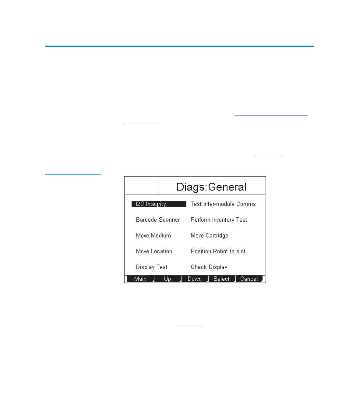
Chapter 5 Running Diagnostic Programs
Running the Barcode Scanner Test
Running the Barcode Scanner Test 5
The Barcode Scanner test causes the bar code scanner to do a complete
inventory of the library, scanning each magazine location for the presence
of a valid bar code label.
Figure 48 Diags:
General Screen
To run the
1 Access the
Barcode Scanner test:
Diagnostics Menu screen (see Accessing the Diagnostics
Menu Screen).
2 Press the
3 Press
Up and Down buttons to select General.
Select.
The GUI displays the
Tandberg Data
Diags: General screen (see figure 48).
4 Press the Up and Down buttons to select Barcode Scanner.
5 Press
Select.
The GUI displays the
the cycle count (see figure 49
Tandberg Data M-Series User’s Guide 77
Diag: Barcode screen, which prompts you to set
). The rightmost number is highlighted.
Page 94
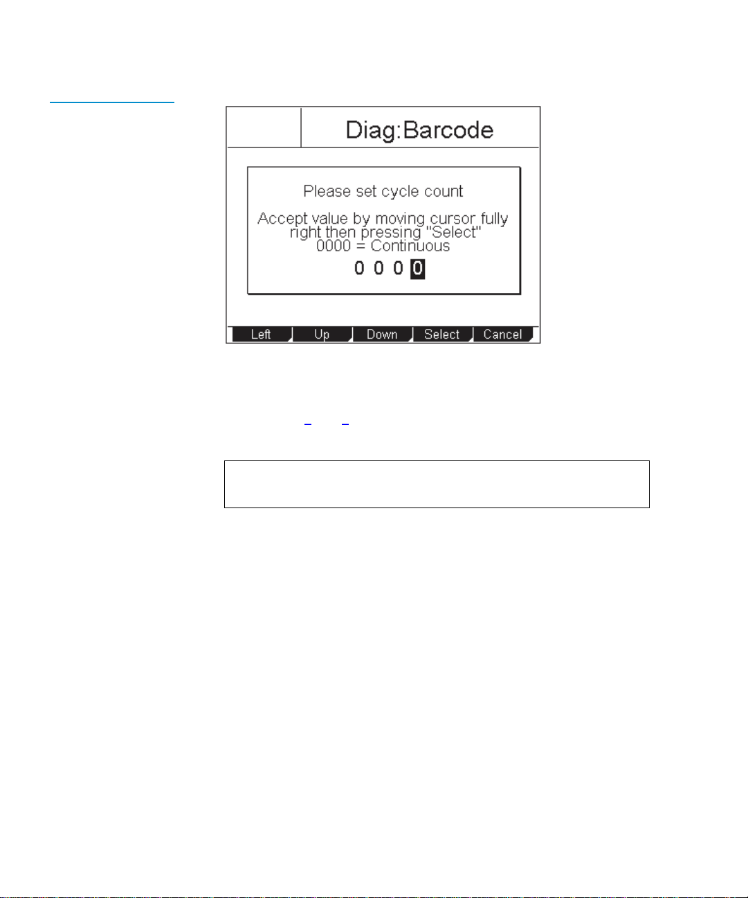
Chapter 5 Running Diagnostic Progra ms
Running the Barcode Scanner Test
Figure 49 Diag:
Barcode Screen
Tandberg Data
6 Press the Up and Down buttons to change the highlighted number.
7 Press
8 Repeat steps 6
Left to move the highlight to the next number.
and 7 as necessary until the desired cycle count
number is displayed.
Note: Setting the cycle count to
0000 causes the test to run
continuously.
9 Press
Right until the cursor is all the way to the right and the Select
button appears.
10 Press
Select to set the cycle count, or press Cancel to return to the
Diags: General screen without running the Barcode Scanner test.
The test starts and the GUI displays a
Running Diag screen. The test
stops automatically after completing the selected number of cycles.
When the test is complete, the GUI displays a screen indicating the
test status.
To abort the test before it completes the selected number of cycles,
press
Stop.
11 Press
Back to return to the Diags: General screen.
78 Tandberg Data M-Series User’s Guide
Page 95
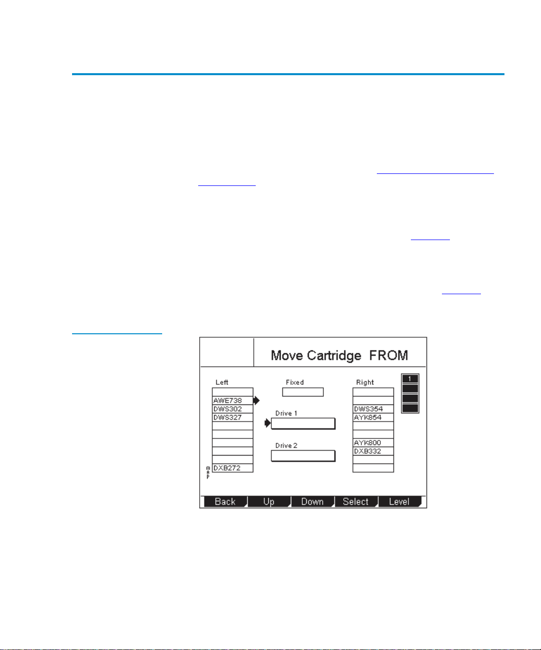
Chapter 5 Running Diagnostic Programs
Running the Move Medium T est
Running the Move Medium Test 5
The Move Medium test simulates the movements performed when a SCSI
Move Medium command is received via the SCSI interface.
Figure 50 Sample
Move Cartridge FROM
Screen
To run the
1 Access the
Move Medium test:
Diagnostics Menu screen (see Accessing the Diagnostics
Menu Screen on page 75).
2 Press the
3 Press
The GUI displays the
4 Press the
5 Press
The GUI displays the
Up and Down buttons to select General.
Select.
Diags: General screen (see figure 48).
Up or Down buttons to select Move Medium.
Select.
Move Cartridge FROM screen (see figure 50). A
flashing arrow indicates the currently selected source element.
Tandberg Data
6 Press the Level button to select the level when the desired source
element is located.
7 Press the
Up and Down buttons to select the source element of the
cartridge.
Tandberg Data M-Series User’s Guide 79
Page 96

Chapter 5 Running Diagnostic Progra ms
Running the Move Medium Test
8 When the flashing arrow is next to the desired source element, press
Select.
Figure 51 Move
Cartridge TO Screen
The GUI displays the
Move Cartridge TO screen (see figure 51). A
flashing arrow indicates the currently selected destination element.
Tandberg Data
9 Press the Level button to select the level where the desired
destination element is located.
10 Press the
Up and Down buttons to select the destination element for
the cartridge.
11 When the flashing arrow is next to the desired destination element,
press
Select.
The GUI displays the
80 Tandberg Data M-Series User’s Guide
Confirm Move Cartridge screen (see figure 52).
Page 97

Figure 52 Sample
Confirm Move
Cartridge Screen
Chapter 5 Running Diagnostic Programs
Running the Move Medium T est
Tandberg Data
12 Verify that the GUI displays the correct source and destination
elements, then press
Confirm.
Figure 53 Diag: Move
Medium Screen
The GUI displays the
Diag: Move Medium screen, which prompts you
to set the cycle count (see figure 53
highlighted.
Tandberg Data
). The rightmost number is
Tandberg Data M-Series User’s Guide 81
Page 98

Chapter 5 Running Diagnostic Progra ms
Running the Move Location Test
13 Press the Up and Down buttons to change the highlighted number.
14 Press
15 Repeat steps 13
Left to move the highlight to the next number.
and 14 as necessary until the desired cycle count
number is displayed.
Note: Setting the cycle count to
0000 causes the test to run
continuously.
16 Press
Right until the cursor is all the way to the right and the Select
button appears.
17 Press
Select to set the cycle count, or press Cancel to return to the
Diags: General screen without running the Move Medium test.
The test starts and the GUI displays a
Running Diag screen. The test
stops automatically after completing the selected number of cycles.
When the test is complete, the GUI displays a screen indicating the
test status.
To abort the test before it completes the selected number of cycles,
press
Stop.
18 Press
Back.
The GUI displays the cycle count screen.
19 Press
Cancel, then Back to return to the Diags: General screen.
Running the Move Location Test 5
The Move Location test is similar to the Move Medium test, except that no
cartridges are actually moved.
When the
from its current location to the destination location.
When the
repeatedly moved between the destination location and a home location,
and will return to the home location at the end of the selected number of
82 Tandberg Data M-Series User’s Guide
Move Location test is cycled once, the robotic hand is moved
Move Location test is cycled more than once, the robotic hand is
Page 99

Chapter 5 Running Diagnostic Programs
Running the Move Location Test
test cycles. The home location depends on whether the destination is a
tape drive or a magazine slot:
• If the destination is a tape drive, the home location is slot 1 of the
level 1 left magazine.
• If the destination is a magazine slot, the home location is the first
installed tape drive.
Figure 54 Diag:
Move-Location Screen
To run the
1 Access the
Move Location test:
Diagnostics Menu screen (see Accessing the Diagnostics
Menu Screen on page 75).
2 Press the
3 Press
Up and Down buttons to select General.
Select.
The GUI displays the
4 Press the
5 Press
Up or Down buttons to select Move Location .
Select.
The GUI displays the
Tandberg Data
Diags: General screen (see figure 48 on page 77).
Diag: Move-Location screen (see figure 54).
6 Press the Up and Down buttons to select the destination for the robotic
hand.
7 Press
Select.
Tandberg Data M-Series User’s Guide 83
Page 100
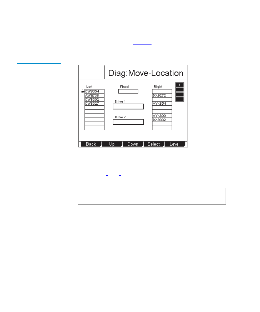
Chapter 5 Running Diagnostic Progra ms
Running the Move Location Test
The GUI displays the Diag: Move Location screen, which prompts you
to set the cycle count (see figure 55
highlighted.
Figure 55 Diag: Move
Location Screen
Tandberg Data
). The rightmost number is
8 Press the Up and Down buttons to change the highlighted number.
9 Press
10 Repeat steps 8
Left to move the highlight to the next number.
and 9 as necessary until the desired cycle count
number is displayed.
Note: Setting the cycle count to
0000 causes the test to run
continuously.
11 Press
Right until the cursor is all the way to the right and the Select
button appears.
12 Press
Select to set the cycle count, or press Cancel to return to the
Diags: General screen without running the Move Location test.
The test starts and the GUI displays a
Running Diag screen. The test
stops automatically after completing the selected number of cycles.
When the test is complete, the GUI displays a screen indicating the
test status.
To abort the test before it completes the selected number of cycles,
press
Stop.
84 Tandberg Data M-Series User’s Guide
 Loading...