

Page 1

User Manual
Software version L2.0
D13640.02
This document is not to be reproduced in whole or in part without permission in writing from:
Page 2

Trademarks and Copyright
User Manual
All rights reserved. This document contains information that is proprietary to TANDBERG. No part
of this publication may be reproduced, stored in a retrieval system, or transmitted, in any form, or
by any means, electronically, mechanically, by photocopying, or otherwise, without the prior
written permission of TANDBERG. Nationally and internationally recognized trademarks and
tradenames are the property of their respective holders and are hereby acknowledged.
Contains iType™ from Agfa Monotype Corporation.
Disclaimer
The information in this document is furnished for informational purposes only, is subject to
change without prior notice, and should not be construed as a commitment by TANDBERG. The
information in this document is believed to be accurate and reliable; however TANDBERG
assumes no responsibility or liability for any errors or inaccuracies that may appear in this
document, nor for any infringements of patents or other rights of third parties resulting from its
use. No license is granted under any patents or patent rights of TANDBERG.
This document was written by the Research and Development Department of TANDBERG,
Norway. We are committed to maintaining a high level of quality in all our documentation.
Towards this effort, we welcome your comments and suggestions regarding the content and
structure of this document. Please fax or mail your comments and suggestions to the attention of:
Research and Development Department
TANDBERG
P.O. Box 92
1325 Lysaker
Norway
Tel: +47 67 125 125
Fax: +47 67 125 234
www.tandberg.net
COPYRIGHT © 2005, TANDBERG
Page 3

Environmental Issues
User Manual
Thank you for buying a product, which contributes to a reduction in pollution, and thereby helps
save the environment. Our products reduce the need for travel and transport and thereby reduce
pollution. Our products have either none or few consumable parts (chemicals, toner, gas, paper).
Our products are low energy consuming products.
Waste handling
No need to send material back to TANDBERG as there are no consumables to take care of.
Please contact your local dealer for information on recycling the product by sending the main
parts of the product for disassembly at local electronic waste stations, marking recyclable parts so
the waste station can disassemble and re-use these parts.
Digital User Manuals
TANDBERG is pleased to announce that it has replaced the printed versions of its User Manuals
with a digital CD version. Instead of a range of different user manuals, there is now one CD which
can be used with all TANDBERG products, in a variety of languages. The environmental benefits
of this are significant. The CDs are recyclable and the savings on paper are huge. A simple webbased search feature helps users directly access the information they need. In addition, the
TANDBERG video systems now have an intuitive on-screen help function, which provides a
range of useful features and tips. The content of the CD can still be printed locally if the need
arises.
Page 4
Operator Safety Summary
User Manual
For your protection, please read these safety instructions completely before operating the
equipment and keep this manual for future reference. The information in this summary is intended
for operators. Carefully observe all warnings, precautions and instructions both on the apparatus
and in the operating instructions.
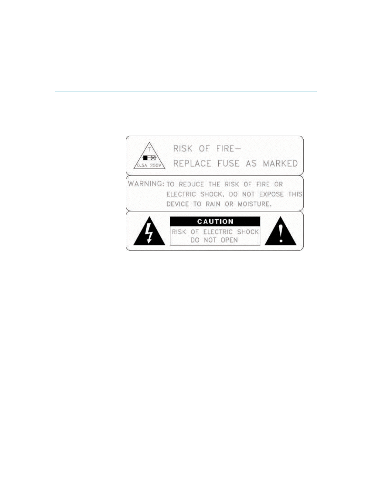
Equipment Markings
The lightning flash
symbol within an
equilateral triangle is
intended to alert the
user to the presence
of uninsulated
“dangerous voltages”
within the product’s
enclosure that may be
of sufficient magnitude
to constitute a risk of
electrical shock.
The exclamation mark
within an equilateral
triangle is intended to
alert the user to the
presence of important
operating and
maintenance
(servicing) instructions
within literature
accompanying the
equipment.
Warnings
Water and moisture - Do not operate the equipment under or near water - for example
near a bathtub, kitchen sink, or laundry tub, in a wet basement, or near a swimming pool
or in areas with high humidity.
Cleaning - Unplug the apparatus from the wall outlet before cleaning or polishing. Do not
use liquid cleaners or aerosol cleaners. Use a lint-free cloth lightly moistened with water
for cleaning the exterior of the apparatus.
Ventilation - Do not block any of the ventilation openings of the apparatus. Install in
accordance with the installation instructions. Never cover the slots and openings with a
cloth or other material. Never install the apparatus near heat sources such as radiators,
heat registers, stoves, or other apparatus (including amplifiers) that produce heat.
Grounding or Polarization - Do not defeat the safety purpose of the polarized or
grounding-type plug. A polarized plug has two blades with one wider than the other. A
grounding type plug has two blades and a third grounding prong. The wide blade or third
Page 5

User Manual
prong is provided for your safety. If the provided plug does not fit into your outlet, consult
an electrician.
Power-Cord Protection - Route the power cord so as to avoid it being walked on or
pinched by items placed upon or against it, paying particular attention to the plugs,
receptacles, and the point where the cord exits from the apparatus.
Attachments - Only use attachments as recommended by the manufacturer.
Accessories - Use only with a cart, stand, tripod, bracket, or table specified by the
manufacturer, or sold with the apparatus. When a cart is used, use caution when moving
the cart/apparatus combination to avoid injury from tip-over.
Lightning - Unplug this apparatus during lightning storms or when unused for long periods
of time.
Servicing - Do not attempt to service the apparatus yourself as opening or removing
covers may expose you to dangerous voltages or other hazards, and will void the
warranty. Refer all servicing to qualified service personnel.
Damaged Equipment - Unplug the apparatus from the outlet and refer servicing to
qualified personnel under the following conditions:
When the power cord or plug is damaged or frayed
If liquid has been spilled or objects have fallen into the apparatus
If the apparatus has been exposed to rain or moisture
If the apparatus has been subjected to excessive shock by being dropped, or the
cabinet has been damaged
If the apparatus fails to operate in accordance with the operating instructions
Page 6

Precautions
User Manual
When installing the TANDBERG 150 MXP, be aware of the following issues:
Never install communication wiring during a lightning storm.
Never install jacks for communication cables in wet locations unless the jack is
specifically designed for wet locations.
Never touch uninstalled communication wires or terminals unless the telephone line has
been disconnected at the network interface.
Use caution when installing or modifying communication lines.
Avoid using communication equipment (other than a cordless type) during an electrical
storm. There may be a remote risk of electrical shock from lightning.
Do not use the communication equipment to report a gas leak in the vicinity of the leak.
Always connect the product to an earthed socket outlet.
The socket outlet shall be installed near to the equipment and shall be easily accessible.
Never install cables without first unplugging the device from the power supply.
1TR6 network type is not approved for connection directly to the telecommunications
network. This network type is only to be used behind a PABX.
This product complies with directives: LVD 73/23/EC, EMC 89/366/EEC, R&TTE
99/5/EEC
Page 7

Table of Contents
1 TANDBERG 150 MXP.................................................................................................................. 1
1.1 At a Glance ............................................................................................................................ 2
1.2 Unpacking and Mounting ....................................................................................................... 4
1.3 Connecting Cables................................................................................................................. 5
1.4 System Configuration............................................................................................................. 7
2 General Use.................................................................................................................................. 8
2.1 The Keypad............................................................................................................................ 9
2.2 On Screen Indicators ........................................................................................................... 12
2.3 Navigation............................................................................................................................ 13
2.4 Make a Call.......................................................................................................................... 14
2.4.1 Make Video Call ............................................................................................................ 15
2.4.2 Make Telephone Call .................................................................................................... 16
2.4.3 Call Settings .................................................................................................................. 17
2.5 Answer an incoming Call ..................................................................................................... 19
2.6 End Call................................................................................................................................ 20
2.7 Phone Book.......................................................................................................................... 21
2.7.1 Global Phone Book ....................................................................................................... 22
2.7.2 New ............................................................................................................................... 23
2.7.3 Edit ................................................................................................................................ 24
2.7.4 Delete............................................................................................................................25
3 Administrator Settings ................................................................................................................ 26
3.1 General Settings .................................................................................................................. 27
3.1.1 Language ...................................................................................................................... 28
3.1.2 System Name................................................................................................................29
3.1.3 Autoanswer ................................................................................................................... 30
3.1.4 Max Call Length ............................................................................................................ 31
3.1.5 Global Phone Book Settings ......................................................................................... 32
3.2 Audio.................................................................................................................................... 33
3.2.1 TTY (Text telephone) .................................................................................................... 34
3.2.2 Alert Tones and Volume................................................................................................35
3.3 Security................................................................................................................................ 36
3.3.1 Encryption ..................................................................................................................... 37
3.3.2 Encryption Mode ........................................................................................................... 38
3.3.4 IP Access Password...................................................................................................... 39
3.3.5 Access Code ................................................................................................................. 40
3.4 Network................................................................................................................................ 41
3.4.1 IP Settings.....................................................................................................................42
3.4.2 H.323 Settings...............................................................................................................44
3.4.3 SIP Settings................................................................................................................... 47
3.4.4 SNMP Settings..............................................................................................................49
3.5 Diagnostics........................................................................................................................... 50
3.5.1 System Information ....................................................................................................... 51
3.5.2 Call Status.....................................................................................................................52
3.6 Restart.................................................................................................................................. 53
4 Appendices................................................................................................................................. 54
4.1 Appendix 1........................................................................................................................... 55
Page 8

1 TANDBERG 150 MXP
1 TANDBERG 150 MXP
Main Features:
H.323/IP bandwidth up to 512kbps
Simplified and easy to use menu
DES and AES Encryption
SIP
Integrated Expressway™ firewall traversal technology
Automatically selection between: H.261, H.263 and H.264 / G.711, G.722 and G.722.1
Quality of Service: Precedence, DiffServ, Automatic downspeeding, Video error
concealment using IPLR
Built-in and automatic: Gain control, Noise reduction and Echo cancellation
Audio and Video mute for privacy
8.4” LCD, 4:3 Screen
Manual Tilt and focus camera
Built-in Microphone and Speakers
Privacy Handset and Headset
Built-in Keypad
Kensington Cable lock
TTY (Text Telephone) support
Power Over Ethernet
Ethernet Switch. No additional LAN port required to connect 150 and PC to your LAN
Handset and Handset Cradle is optional and detachable
True Localization with enhanced language support
1
Page 9
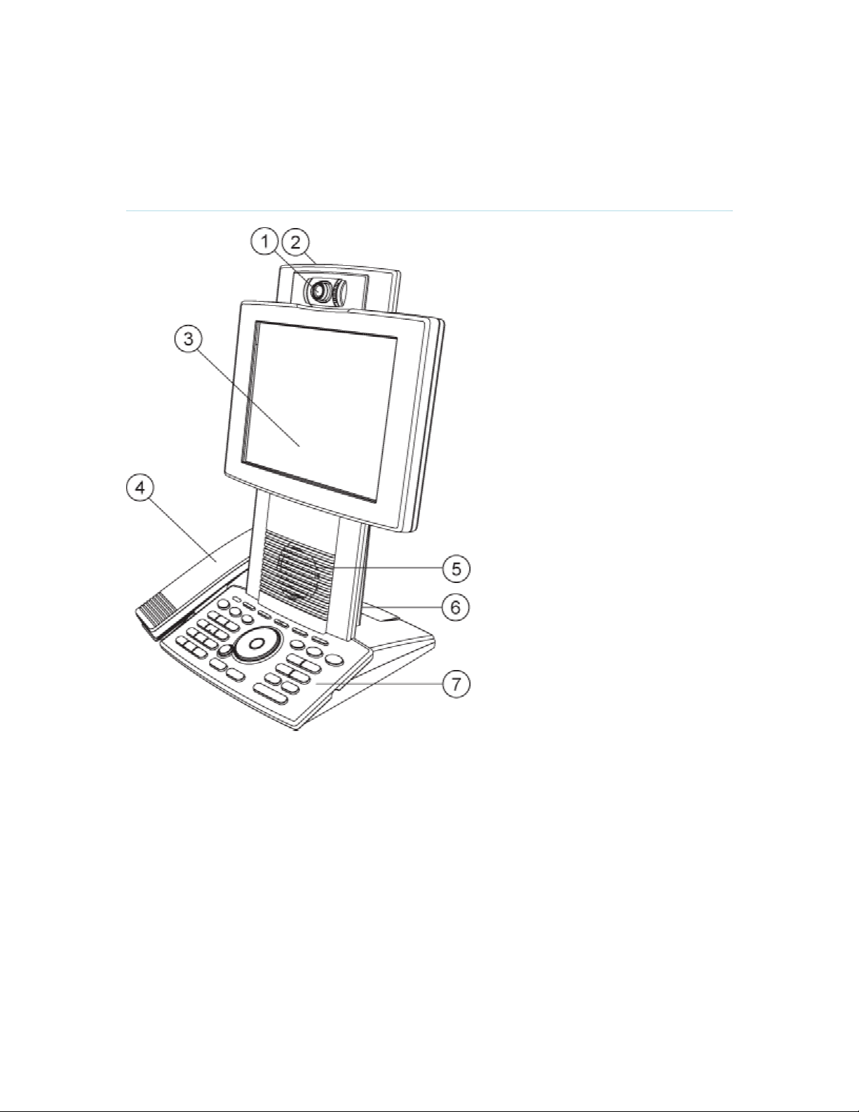
1.1 At a Glance
1 TANDBERG 150 MXP
1. Camera
The camera has manual tilt and focus. Turn the lens to adjust focus. (Tip! Press Selfview first to
see your video picture). Tilt the camera by manually adjusting the tilt angle with the wheel to the
right of the lens.
2. Microphone (located at the top of the product)
3. LCD Monitor
4. Handset
Handset is not included with the TANDBERG 150 MXP, but is an accessory device. Contact your
TANDBERG representative for more information.
5. Speaker
6. Camera Lens Cap Docking (at the back side)
2
Page 10

1 TANDBERG 150 MXP
Use the Camera lens cap at the back side of the product to cover the lens when the product is not
in use. The camera lens cap protects the lens and also assures you from involuntary
broadcasting of your video image.
7. Keypad
The keypad contains all the keys you need to control the system. See chapter 2.1 The Keypad for
more information.
3
Page 11
1 TANDBERG 150 MXP
1.2 Unpacking and Mounting
Unpacking the system
The system lies fully assembled in the box. Remove the accessories box and carefully lift the
system out of the box. To protect the camera lens while installing, it is recommended to keep the
camera lens cap on. In the accessories box you find:
LAN cable
Power adapter and power cable
Handset
Handset is not included with the TANDBERG 150 MXP, but is an accessory device. Contact your
TANDBERG representative for more information.
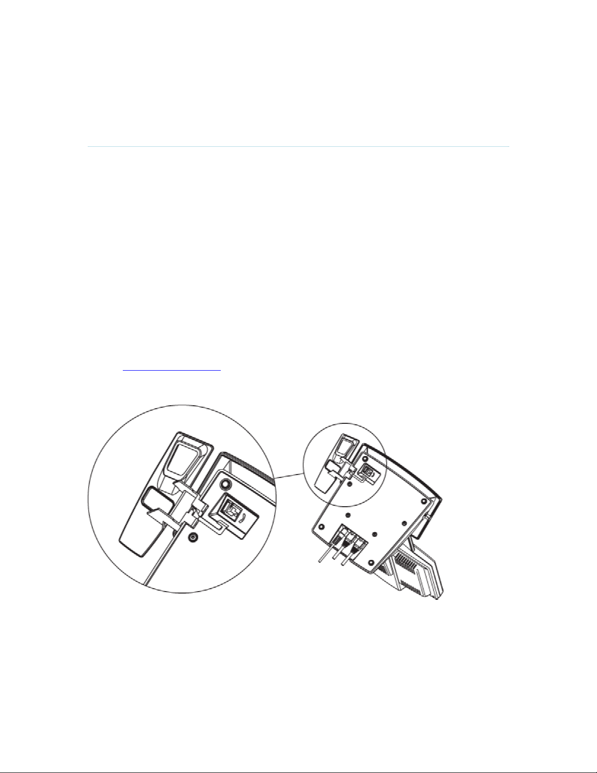
Mounting of the handset
Slide the handset bracket into the tracks at the underside of the system. Place the system in an
upright position and lay the handset in its place. The handset is held in place by magnets. See
chapter 1.3 Connecting Cables for how to connect the handset cable.
4
Page 12
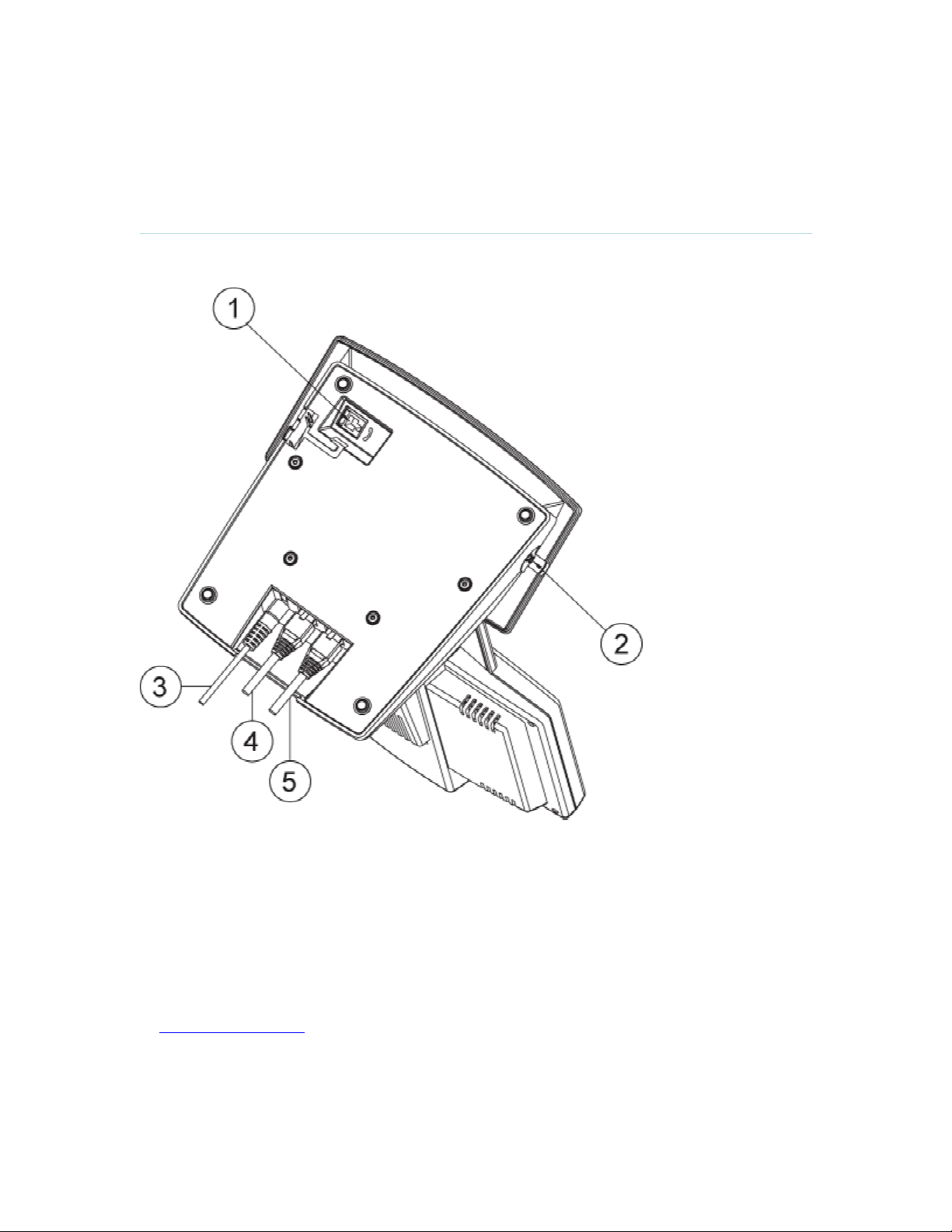
1.3 Connecting Cables
1 TANDBERG 150 MXP
Connect the cables as shown on the figure:
1. Plug for handset (optional)
Handset is not included with the TANDBERG 150 MXP, but is an accessory device. Contact
your TANDBERG representative for more information.
2. Plug for headset (optional)
The TANDBERG 150 MXP has a 2.5mm 3-pole mini-jack connector at its right side marked
with a headset symbol. This allows the user to connect a standard telecommunications headset
to the system. Headsets with the microphone positioned in front of the user’s mouth, connected
to the earphone through a rod, tend to give more echo than earbud headsets with the
microphone attached to the cord. TANDBERG recommends the Plantronics MX100 headset
(www.plantronics.com, products → mobile). Note that the maximum outer diameter of the plug
must be 7,0 mm or smaller. A plug with a bigger outer diameter will not fit the unit. Alternatively
an extension cord may be used.
3. Power cable
5
Page 13

4. LAN 1
5. LAN 2
1 TANDBERG 150 MXP
6
Page 14

1.4 System Configuration
1 TANDBERG 150 MXP
Before you begin it is recommended to configure your system. Navigate through the settings
using the arrow keys and OK. Remember to press the Save button on the bottom of each menu
to save your changes. Press Cancel (x) to return to the previous Menu.
General configuration:
1. Open the General Settings menu
Press the Settings key on the keypad to open the Settings menu. Select General Settings.
2. Language
Press OK in the Language field and select the language you want to use from the list.
3. System Name
Give your system a name. Use the # key to change between lower case and upper case letters.
4. Auto answer
Decide whether you would like the system to let calls through automatically (Auto answer On), or
if you want to answer the call manually (Auto answer Off). The option On + Mic Off means that
the system automatically will answer incoming calls and switch the microphone off when the call
is connected. Press Mic Off to switch the microphone back on.
5. Max Call Length
You can limit the maximum length of your calls. If your call exceeds the maximum Call Length,
the call will disconnect automatically.
6. Save changes
Remember to save changes by selecting the Save button on the bottom of the menu and
pressing OK.
7
Page 15

2 General Use
Wake up the system
When all cables are connected as described in chapter 1.3 Connecting Cables, the system is
ready for use.
The Welcome Screen
When the system is powered, you will see the welcome screen. Your dial in number is displayed
in the upper right corner. The on-hook telephone icon tells you that you are currently not in a call.
Press OK or Cancel to hide the welcome screen. Press OK or Cancel to bring it back.
To check your video image, press Selfview on the keypad (see chapter 2.1 The Keypad for
further information). Press Selfview again to go back to the welcome screen.
8
Page 16
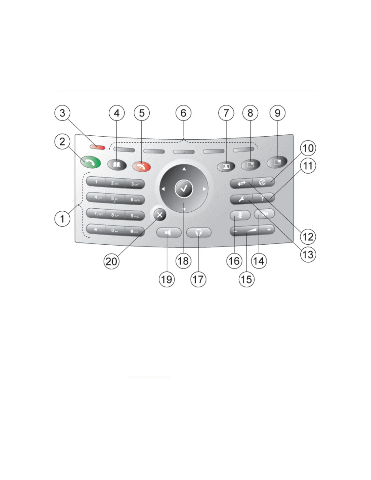
2.1 The Keypad
2 General Use
1. Number keys
Use Number keys to dial video numbers. Use the star key to get the dot sign when dialing an IP
number.
When you are in an input field where letters are required, the system automatically goes to letter
mode. Writing letters works like on a mobile phone. Press the key that corresponds to your
desired letter. Press the key as many times as you need to get the right letter. Change to lower or
upper case letters with the # key, and space with the 0 key.
2. Call key
Press the Call key to open the call menu. When you have dialed a number, press the call key to
place the call (see chapter 2.3 Make a Call for more information).
3. Notification lamp
A red lamp is lit to indicate that you have and incoming call. The lamp is also lit when you power
up the system. When the lamp turns off, the system is ready for use.
4. Phone Book
9
Page 17

2 General Use
Press Phone Book to open the systems phone book. Store and recall your video contacts via the
system Phone Book for easy placement of calls (see chapter 2.6 Phone Book for more
information).
5. End Call
Use the red End Call key to end the current call.
6. Soft keys
For future releases.
7. Selfview
Selfview displays the picture of yourself. Press Selfview again to turn selfview off.
8. PIP
Press PIP (Picture In Picture) to get a smaller picture in addition to the full screen picture. The
PIP is placed in the top right corner of the screen. Press PIP again to move it to the other corners
of the screen. The fifth time you press PIP, it will disappear.
9. Brightness
Brightness lets you adjust the monitor brightness.
10. Services
For future releases.
11. Help
Press Help to get a quick guide about how to use the system.
12. Call Register
Press Call Register to se a list of your latest calls, both outgoing, incoming and lost calls.
13. Administrator Settings
Press Administrator Settings to open the settings menu. Administrator Settings contain all the
settings of the system (see chapter 3 Settings for more information).
14. Privacy
When the Privacy key is pressed, no camera image will be sent out from your system. The
Privacy key is lit when the camera is off. An indicator on the screen also appears as you press
Privacy. Press the Privacy key again to deactivate privacy. Use Privacy to prevent others from
seeing your video image.
15. Volume
Volume + and – adjusts the volume of the speaker. An indicator on the screen shows the volume
level.
16. Mic Off
Press Mic Off to mute your microphone. The Mic Off key is lit when the microphone is off. An
indicator on the screen also appears as you press Mic Off. Press the Mic Off key again to
deactivate Mic Off. Use Mic Off to mute your outgoing audio.
17. Headset
Press Headset to activate headset. Remember to plug in your headset in advance (see chapter
1.3 Connecting Cables). The Headset key is lit when it is active. Press Headset again to
deactivate.
18. Arrow keys and OK
Use Arrow keys to navigate in menus. Press OK to select menu items.
10
Page 18

2 General Use
19. Speaker
Press Speaker to activate the speaker. The Speaker key is lit when the speaker is active. Press
Speaker again to turn the speaker off.
20. Cancel
Cancel takes you back one step in the menu system. Use Cancel also to delete characters in an
input field.
11
Page 19
2.2 On Screen Indicators
2 General Use
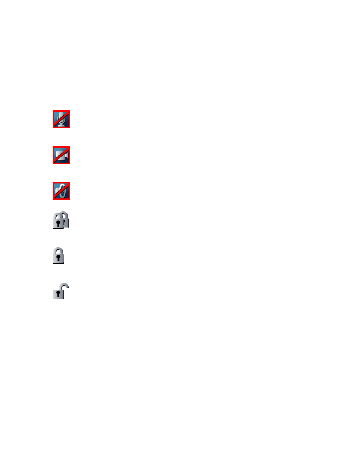
The system has a number of icons signaling different settings:
Microphone Off
This indicator is shown when the microphone is turned off. Press the Mic off
button again to turn the microphone back on.
Privacy
This indicator is shown when the Privacy key on the keypad is activated. No
camera images are sent from your system when the privacy indicator is displayed.
Press the Privacy key again to deactivate privacy.
Volume Off
This indicator is shown when the volume is turned off. Press Volume + to turn the
volume back on.
Secure Conference, AES
This double padlock indicator is shown when AES encryption (Secure
Conference) is active.
Secure Conference, DES
This padlock indicator is shown when DES encryption (Secure Conference) is
active.
Not Secure Conference
This open padlock indicator is shown during the initialization phase for encryption.
During this period the call is not secure.
12
Page 20

2.3 Navigation
2 General Use
Arrow keys and OK
Navigate in the menu with arrow keys. The orange selector on screen
shows the selected item. Press OK to select.
Back/Cancel button
The X button in the menu corresponds with the X key on the remote.
13
Page 21

2.4 Make a Call
2 General Use
To open the call menu, do one of the following:
Press the green button on the keypad
Press a number key
Press the speaker button on the keypad
Press the headset button (remember to plug in your headset first)
Lift up the handset (handset is accessory device with TANDBERG 150 MXP)
All of these actions will result in a dial tone and you can start dialing. You can enter a number
manually in the input field or select the book icon to select a contact from the phone book.
The TANDBERG system can make both video calls and telephone calls. For video calls, choose
Place Video Call in the call menu. For telephone calls, choose Place Telephone Call. Call
Settings specifies the quality of the call. In most cases you can leave call settings unchanged.
Choose among the buttons:
Make Video Call
Make Telephone Call
Call Settings
14
Page 22

2.4.1 Make Video Call
2 General Use
How to make a video call:
1. Press the green key on the keypad (or any of the other possibilities mentioned in chapter
Make a Call) to open the Call menu.
2. Dial a video number manually, see details below, or select a conference participant from
the Phone Book, see 2.7 Phone Book for details.
3. Press the green key on the keypad or move the orange selector down to the Place Video
Call icon and press OK to start the video call.
When dialing manually, toggle between ABC/abc by pressing the # button on the keypad and
between abc/123 by holding the # button for one second. Use a star as separator in IP
addresses. If a system is registered on a gatekeeper or border controller with DNS support, there
are several ways to call into the system:
<IP address>
<E.164>
<H.323 ID>
<H.323 ID>@<domain>
<E.164>@<domain>
See 3.4.2 H.323 Settings for details.
15
Page 23

2.4.2 Make Telephone Call
2 General Use
The TANDBERG system has great audio- as well as video performance. Use the system both as
a videophone and a telephone!
How to make a telephone call:
1. Press the green key on the keypad (or any of the other possibilities mentioned in chapter
Make a Call) to open the Call menu.
2. Dial a telephone number with the number keys (use a star as separator in IP addresses).
3. Move the orange selector down to the Place Telephone Call icon and press OK to start
the telephone call.
16
Page 24

2.4.3 Call Settings
2 General Use
The field on the right in the call menu displays Call Settings. Call Settings gives you the
opportunity to specify Call Type and Bandwidth.
How to use Call Settings:
1. Press the green key on the keypad (or any of the other possibilities mentioned in chapter
Make a Call) to open the Call menu.
2. Move the orange selector to the Call Settings field on the right of the call menu and press
OK.
3. Make desired changes to Call Type and Bandwidth.
4. Press OK to save. The new call settings will be displayed in the Call settings field.
Call Type
Bandwidth
Net
Call Type can be set to Video Call (default) or Telephone Call. Using Video,
the system will try to connect as a video call. Some network configurations
will cause the fallback to a telephone call to fail. In these cases, you should
set the call type to telephone and the call will be placed as a telephone type
only.
Bandwidth decides the quality of the video picture. The system will, by
default, connect using Auto Bandwidth. This means that the system will
establish a connection using a proper bandwidth for your call. The typical
bandwidth used for IP calls is 384kbps. When bandwidth is set to auto, the
unit will default to 384kbps.
The Net alternatives are: H.323 and SIP.
If a gatekeeper is present, you may place IP-calls using “telephone-style”
numbers (an E.164 alias), according to the numbering plan implemented in
the gatekeeper. The gatekeeper will then translate the dialed number into an
IP-address (see 3.4.2 H.323 Settings for more information about
gatekeepers).
17
Page 25

2 General Use
Use Set as
Default
If you want to change the default Call Settings, make the desired changes to
the Call Settings and Press Set as Default. Press OK to Save. These
settings will now be the default settings for all future manually dialed calls.
18
Page 26

2.5 Answer an incoming Call
2 General Use
How to answer an incoming call:
1. To accept an incoming call, press the green key or press OK when the Accept button on
screen is selected.
2. To reject and incoming call, press the red key or press OK when the Reject button on
screen is selected.
Alternative ways to answer a call are:
Pressing the speaker button
Pressing the headset button (if a headset is connected)
Lifting up the handset (if a handset is connected)
If Auto Answer is set to On, an incoming call will connect automatically. You can set Auto Answer
On, On + Mic Off or Off in Settings - General Settings, see chapter 3.1 General Settings.
19
Page 27

2.6 End Call
2 General Use
How to end a call:
1. Press the red key on the keypad. A dialog box appears on the screen.
2. Press the red key on the keypad again or OK to confirm that you want to end the call.
Press Cancel to continue the call.
If you are using the handset, you can end the call by hanging up.
20
Page 28

2.7 Phone Book
2 General Use
The local Phone Book stores up to 200 contacts. Using the Phone Book is time saving and
makes sure you do not inadvertently call the wrong number.
The contacts are sorted alphabetically. Navigate the phone book with arrow keys or letter keys,
searching on the first letter (like on a mobile/cellular phone). Press arrow to the left to select a
button. You will see that the last selected contact will be marked.
Call History is found on top of the Phone Book entry list. Press Call History to see your placed
and incoming calls. For unanswered calls are listed under Missed Calls.
How to make a call using the phone book:
1. Press the Phone Book key on the keypad.
2. Find your desired contact using the arrow keys or searching on the first letter with the
letter keys.
3. Press the green call key on the keypad or press arrow key left to select the Call Now
icon. Alternatively, press OK to select the contact. You will go to the Call menu, where
you may edit the number or call settings before you place the call.
4. Wait for the call to connect.
Note that the number of the selected contact is displayed at the bottom line.
21
Page 29

2.7.1 Global Phone Book
2 General Use
If your system is connected to an external management system like the TANDBERG
Management Suite (TMS), it is possible to use a central contact list from the management
system. These contacts can not be changed locally by the system, only from the management
system. If you need to modify a number before dialing it, you can do so by hitting ok after
selecting the entry, and modifying the number before placing the call. The changes are not saved
in the contact.
The Global Phone Book can contain an unlimited amount of contacts. Using search makes it
easier to find your right contact.
How to search in the Global Phone Book:
Search on first letters with the number keys like on a mobile phone. Press "2" three times
to jump to the letter "c" in the list.
Press the Search button on the left of the Phone Book. Type a name and press OK. The
system will list all entries that contains this letter combination. Press the button called
"Top" to get back to the alphabetical Global Phone Book list.
For contacts you use often, you may consider copying them from the Global Phone Book to your
Local Phone Book. This makes them easier to find if your Global Phone Book is large, but the
local copy would not be updated if the Global Phone Book contact is changed.
How to copy a contact from the Global Phone Book to the Local Phone Book:
1. Move the yellow selector down to the desired contact in the global phone book.
2. Press arrow key left, select the Copy to Local button and press OK.
3. The contact is copied to your local phone book.
22
Page 30

2.7.2 New
2 General Use
Select the New button to make a new contact. You can store up to 200 contacts in your local
phone book. To make a new contact, you must specify a Name and Number. Use the number
and letter keys on the remote control (in the Name field you will automatically write letters, in the
number field you will automatically write numbers). Call Type, Net and Bandwidth are put to
default if you don’t make changes. Press OK to save.
23
Page 31

2.7.3 Edit
2 General Use
To edit a contact, highlight the contact and press arrow left. Press arrow key down to select the
Edit button. In the edit window you can edit Name, Call Type, Net, Number and Bandwidth. Press
OK to save.
24
Page 32

2.7.4 Delete
2 General Use
To delete a contact, highlight the contact and press arrow left. Press arrow key down to select the
Delete button and press OK. Confirm by pressing OK again.
25
Page 33

3 Administrator Settings
Settings contain all the settings of the system. Making changes to Settings will change the
behaviour of the system.
Administrator Settings contain:
General
Audio
Security
Network
Diagnostics
Restart
26
Page 34

3.1 General Settings
273 Administrator Settings
When installing the system, go through the General Settings menu to ensure that you have the
right settings for your system, see chapter 1.4 System Configuration.
General Settings contain:
Language
System Name
Autoanswer
Max Call Length
Global Phone Book Settings
27
Page 35

3.1.1 Language
283 Administrator Settings
The system supports 13 different languages for its on-screen menus; English, German, French,
Norwegian, Swedish, Italian, Spanish, Portuguese, Chinese Simplified, Chinese Traditional,
Japanese, Russian and Korean. Select the preferred language and press OK to save.
28
Page 36

3.1.2 System Name
293 Administrator Settings
System Name is blank by default. System name can be alphanumeric and up to 50 characters
long. Follow the installation procedure to enter a System Name.
29
Page 37

3.1.3 Autoanswer
303 Administrator Settings
The auto answer setting decides whether an incoming call is put through automatically or
manually.
On
On+
Mic
Off
Off
The system will automatically answer all incoming calls.
The system will automatically answer all incoming calls and switch the microphone
off when the call is connected. Press Mic Off to switch the microphone back on.
You must manually answer all incoming calls by pressing OK or the Call key.
30
Page 38

3.1.4 Max Call Length
313 Administrator Settings
This feature will automatically end both incoming and outgoing calls when the call time exceeds
the specified Max Call Length. Max Call Length can have the following values: 0-999 (minutes),
where 0 means off.
31
Page 39

323 Administrator Settings
3.1.5 Global Phone Book Settings
Global
On
Off
IP address
Enter the IP address of the management system that provides the Phone Book.
Path
The Path indicates the function of the management system.
Global Phone Book is available in the menu.
Global Phone Book is hidden from the menu and is unavailable for users.
32
Page 40

3.2 Audio
333 Administrator Settings
Audio contains the settings:
TTY (Text telephone)
Alert Tones and Volume
33
Page 41

3.2.1 TTY (Text telephone)
343 Administrator Settings
A TTY is a special device that lets people who are deaf, hard of hearing, or speech-impaired use
the telephone to communicate, by allowing them to type messages back and forth to one another
instead of talking and listening. A TTY is required at both ends of the conversation in order to
communicate.
To use a TTY, you connect the TTY device to the 2.5mm jack on the right side of the unit and set
TTY to On in the Audio menu. Then, type the message you want to send on the TTY's keyboard.
As you type, the message is sent over the phone line, just like your voice would be sent over the
phone line if you talked. You can read the other person's response on the TTY's text display.
34
Page 42

3.2.2 Alert Tones and Volume
353 Administrator Settings
Video Call Alert Tone and Telephone Alert Tone
To help distinguish between incoming video calls and ordinary telephone calls, it is recommended
to use different ringing tones for video calls and telephone calls.
Alert Volume
You may change the volume level for the selected ringing tone.
Key Sound
On
Off
There will be a sound indicator when pressing keys on the remote control.
There will be no sound when pressing keys on the remote control.
35
Page 43

3.3 Security
363 Administrator Settings
Security contains the settings:
Encryption
Encryption Mode
Administrator Password
IP Access Password
Access Code
36
Page 44

3.3.1 Encryption
373 Administrator Settings
(Country specific)
Auto
Off
Technical encryption information like encryption algorithm and encryption check code can be
found in the Call Status menu.
The system will try to set up calls using encryption.
If the far end system supports encryption (AES or DES), the call will be encrypted.
If not, the call will proceed without encryption. If the far end supports encryption,
the systems will initiate encryption after the call is connected (an ‘open padlock’
symbol will be displayed). When encryption has been established, a ‘closed
padlock’ symbol will be displayed.
The system will not send or receive encrypted data.
37
Page 45

3.3.2 Encryption Mode
383 Administrator Settings
Auto
AES
DES
The system will try to use the most secure encryption - AES, dependent on the
capabilities of the other sites. If all the other sites do not support AES-encryption,
DES encryption will be tried.
The system will try to use AES with 128 bits encryption when setting up calls. If
AES is not supported by the other site(s), no other type of encryption will be
initiated.
The system will always try to set up the call using DES with 56 bits encryption. If
all other sites do not support DES, no other type of encryption will be initiated.
38
Page 46

3.3.4 IP Access Password
393 Administrator Settings
By setting an IP Access Password on the system, all access to the system using IP (Telnet, FTP
and WEB) requires a password. This password can be enabled from telnet or data port using the
command: ippassword <ip-password>. The default IP password is "TANDBERG".
To remove this password, delete the stars shown in the input field in the menu. You can also
remove the password from the data port using the command: "ippassword ”. From telnet, this is
only possible by first entering the correct password.
39
Page 47

3.3.5 Access Code
403 Administrator Settings
An access code will help you control the use of the system. All users must enter a code to identify
themselves and the call will be charged on their account. Access Codes are handy for group
systems where there are more users or divisions that share the costs of using the system. Access
Code can be put to On and Off.
On
Off
When making a call, an Access Code dialog box will be shown. The user must
enter the correct password in order to put the call through.
No password is necessary to make a call.
40
Page 48

3.4 Network
413 Administrator Settings
The network menu contains:
IP Settings
H.323 Settings
SIP Settings
SNMP Settings
41
Page 49

3.4.1 IP Settings
423 Administrator Settings
Remember to restart the system after making changes to IP Settings. Changes in IP Settings
menu will not have any effect before the system is restarted.
IP-assignment
DHCP (Dynamic Host Configuration Protocol) can be selected when a DHCP server is present.
DHCP
Static
IP-address
IP-address defines the network address of the codec. This address is only used in static mode. In
DHCP-mode, the assigned IP-address can be found on the Welcome Menu.
IP-subnet mask
IP-subnet mask defines the type of network. This address is only used in static mode. Your LAN-
administrator will provide the correct value for this field.
Gateway
When using DHCP, the default gateway will be set automatically. If the LAN utilizes static IP
addresses, IP address, subnet mask, and default gateway must be specified by the LAN
administrator.
Ethernet Speed
Auto
10/Half
10/Full
100/Half
100/Full
IP Access Password
IP-address, IP-subnet mask and Gateway are not used because the DHCP server
assigns these parameters.
The system’s IP-address, IP-subnet mask and Gateway must be specified in the
IP-address field.
The codec will auto-detect the speed/duplex on the LAN.
The codec will connect to the LAN using 10Mbps speed/Half Duplex.
10 Mbps speed/Full Duplex.
100 Mbps speed/Half Duplex.
100 Mbps speed/Full Duplex.
42
Page 50

433 Administrator Settings
By setting an IP Access Password on the system, all access to the system using IP (Telnet, FTP
and WEB) requires a password. The default IP Access Password is “TANDBERG”.
43
Page 51

443 Administrator Settings
3.4.2 H.323 Settings
E.164 alias
This is the E.164 address of the system. The E.164 address is equivalent to a telephone number,
sometimes combined with access codes. Valid characters are 0-9,* and #. When using a
gatekeeper, the system will send a message to the gatekeeper containing both the E.164 address
and the system name of the system. The system will not register with the gatekeeper if the E.164
alias is not set.
H.323 Call Setup
Direct
Gatekeeper
CallManager
An IP-address must be used in order to make a H.323 call. The system will
not use a gatekeeper or CallManager.
The system will use a gatekeeper to make a H.323 call.
The system will use a CallManager to make a H.323 call.
Gatekeeper Discovery
Auto
Manual
The system will automatically try to register on any available gatekeeper. If a
gatekeeper responds to the request sent from the codec within 30 seconds this
specific gatekeeper will be used. If no gatekeeper responds, the system will not
use a gatekeeper for making H.323 calls and hence an IP-address must be
specified manually.
The system will use a specific gatekeeper identified by Gatekeeper IP-address.
Gatekeeper IP-address
This is the gatekeeper IP-address that is used if you specify H.323 Call Setup: Gatekeeper and
Gatekeeper Discovery: Manual.
Note that if your system is part of a TANDBERG Expressway™ firewall traversal solution
and is placed outside the firewall, you should register the IP address of your Border
Controller as the Gatekeeper IP-address and set H.323 Call Setup to Gatekeeper.
44
Page 52

453 Administrator Settings
Call Manager Address
This is the call manager IP-address that is used if you specify H.323 Call Setup: Call Manager.
Advanced H.323 Settings
The Advanced H.323 Settings only have an effect if they are supported by your IP infrastructure.
NAT
NAT, Network Address Translation, is used in small LAN’s, often home offices, when a PC and a
videoconferencing system are connected to a router with NAT support. NAT support in the
videoconferencing system enables proper exchange of audio/video data when connected to an
external videoconferencing system (when the IP traffic goes through an NAT router). When NAT
is On, the NAT Server Address will be shown in the startup-menu: "My IP Address: 10.0.2.1
(NAT)".
NAT Address
This must be the external/global IP-address to the router with NAT support. Packets sent to the
router will then be routed to the codec. In the router, the following ports must be routed to the
codec’s IP-address:
Port 1720
Port 55555560
Port 23262365
Please contact your TANDBERG representative for further information.
QoS Type
Off
Diffserv
IP
Precedence
IP Precedence Video
Used to define which priority audio, video, data and signaling should have in the network. The
higher the number, the higher the priority. The priority ranges from 0(off) - 7 for each type of
packets.
Auto will provide the following priority:
No QoS is used.
Diffserv QoS method is used. Please see below for details.
IP Precedence QoS method is used. Please see below for details.
45
Page 53

463 Administrator Settings
Audio
Video
Data
Signaling
IP Type of Service (TOS) helps a router select a routing path when multiple paths are available.
Delay
Throughput
Reliability
Cost
IP Precedence Telephony
Used to define which priority audio should have in the network for telephone calls. The higher the
number, the higher the priority. The priority ranges from 0(off) - 7 for each type of packets.
Auto will provide the following priority:
Audio
Diffserv Video
Used to define which priority Audio, Video, Data and Signaling packets should have in an IP
network. The priority ranges from 0 to 63 for each type of packets.
Diffserv Telephony
Used to define which priority Audio packets should have in an IP network for telephone calls. The
priority ranges from 0 to 63 for each type of packets.
H.323 Ports
Static
Dynamic
4
4
3
6
Tells the router to minimize the delay.
Tells the router to maximize the throughput.
Tells the router to maximize the reliability.
Tells the router to minimize the cost.
4
When selecting static H.323 ports for TCP connections the ports 5555 or 5556
will be used for Q.931 and H.245 respectively.
The system will allocate which ports to use when opening a TCP connection.
The reason for doing this is to avoid using the same ports for subsequent calls
as some firewall consider this as a sign of attack.
46
Page 54

3.4.3 SIP Settings
473 Administrator Settings
Proxy Settings
To be able to make a call with an E.164 alias or user name, Proxy must be set to On and an
Outbound Proxy IP-address must be specified. Outbound Proxy uses alias to look up the far end
IP-address.
Use Proxy
On
Off
Proxy Address
The Proxy Address defines the Outbound Proxy IP-address.
Port
Set the desired Proxy port when not using the standard port 5060.
The system will use Outbound Proxy for outgoing calls
Outbound Proxy is not used
Registrar Settings
To call into the system with E.164 alias or user name the server on which the system alias should
be registered must be specified. Normally registrar is set to Same as Proxy, but if registered on
another server Use Registrar must be set to On and the address must be specified in Registrar
Address.
Use Registrar
On
Off
Same as
Proxy
Registrar Address
This is the Registrar IP-address.
Register URL / E.164 number for incoming calls
Registrar is not used
Use the same IP-address and Port as Proxy
47
Page 55

483 Administrator Settings
Port
Set the desired Registrar port when not using the standard port 5060.
Full Name
This is the name that will be displayed in your URL. Example: "Eric Harper"
eric.harper@example.com
Username
This is your username or your E.164 number in your URL. Example: "Eric Harper"
eric.harper@example.com
Domain
The domain of your URL. Example: "Eric Harper" eric.harper@example.com
Expires
This is the default time your URL registration is valid. It controls how often you register with your
registrar. The registrar may override this value when registering.
48
Page 56

3.4.4 SNMP Settings
493 Administrator Settings
SNMP Settings
SNMP Trap Host identifies the IP-address of the SNMP manager. SNMP (Simple Network
Management Protocol, SNMP Ver 1) is used for monitoring and configuring of different entities in
a network. The system's SNMP Agent responds to requests from SNMP Managers (a PC
program etc.). SNMP traps are generated by the agent to inform the manager about important
events.
Traps can be sent to multiple SNMP Trap Hosts. Enter the IP address of up to three SNMP
managers. All traps will then be sent to the hosts listed.
SNMP Community names are used to authenticate SNMP requests. SNMP requests must have a
‘password’ in order to receive a response from the SNMP agent in the codec. Note that the
SNMP Community name is case sensitive. The default password is "public".
49
Page 57

3.5 Diagnostics
503 Administrator Settings
Diagnostics contain:
System Information
Call Status
50
Page 58

3.5.1 System Information
513 Administrator Settings
Select System Information to view system numbers, line status, software version and other useful
information.
System Information contains:
System Name
My IP Number
My IP Address
Gatekeeper
Software Version
Serial No
MAC address
Ethernet Speed PC
Ethernet Speed SW
51
Page 59

3.5.2 Call Status
523 Administrator Settings
Comprehensive information about the call is available through the Call Status window. The menu
has two columns, one for transmitted and one for received audio/video information.
52
Page 60

3.6 Restart
533 Administrator Settings
Restart the system by pressing the Restart button. You are prompted with a dialog box saying:
Do you want to restart the system? Press OK to restart, press Cancel (X) to abort.
53
Page 61

4 Appendices
Appendix 1: Declaration of Conformity
54
Page 62

4.1 Appendix 1
4 Appendices
Declaration of Conformity
Contact your TANDBERG representative for a Declaration of Conformity.
IVCi
 Loading...