

Page 1
VXA-172 AND VXA-320 (VXA-3) SCSI
APE DRIVE QUICK START GUIDE
T
Use these instructions to get your VXA-172 or VXA-320 (VXA-3) tape
drive up and running quickly. For additional information, refer to the
VXA-172 Product Manual or VXA-320 (VXA-3) Product Manual at
www.tandberg.com.
Your VXA-172 or VXA-320 (VXA-3) tape drive has a wide Ultra160
low-voltage differential (LVD) SCSI interface. The drive is available in
two models: an internal model for installation into an enclosure or an
external model that can be placed on a flat surface.
1. Remove the cover plate from the host computer’s drive bay,
according to the system manufacturer’s instructions.
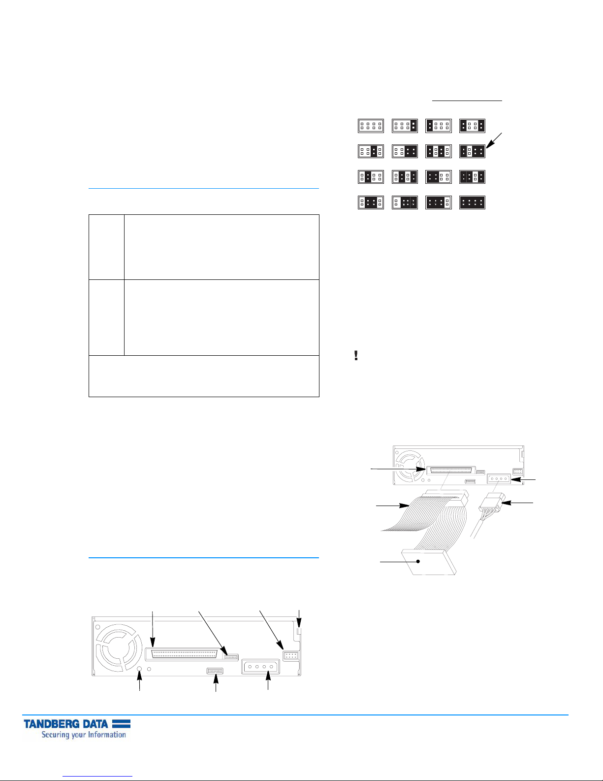
2. Set the SCSI ID by using flat-nosed pliers to position the jumpers
for the desired ID, as shown. Select a SCSI ID for the drive which
is unique. The host bus adaptor and any peripherals attached to
the SCSI bus must all be set to unique SCSI IDs. (The terminator
does not use a SCSI ID.) SCSI ID Jumper Block
Address 0
Address 2 Address 3 Address 10 Address 11
Address 4 Address 5 Address 12 Address 13
Address 1 Address 8 Address 9
:
Factory
setting
(ID 11)
1| PREPARING FOR INSTALLATION
Make sure you have the required equipment, as described below.
Internal
Model
External
Model
Important! Both VXA-172 and VXA-320 SCSI tape drives are Ultra
160 SCSI devices and require a minimum Ultra 160 non-RAID SCSI
adapter card, Ultra 160 rated SCSI cabling, and an Ultra 3 Active
SCSI terminator.
LVD SCSI host bus adapter and any necessary drivers
installed in the host computer (do not use a SCSI RAID
controller or an HVD controller)
SCSI cable, wide LVD, 68-pin connector
LVD/SE terminator, if necessary
VXAtape cartridges, available from your media supplier
LVD SCSI host bus adapter and any necessary drivers
installed in the host computer (do not use a SCSI RAID
controller or an HVD controller)
Power cord (included)
LVD/SE terminator (included)
SCSI cable, wide LVD, 68-pin male connector
VXAtape cartridges (included with VXA-3)
QUICK START GUIDE-
Before beginning the installation:
Inspect the shipping box for damage. If you find any damage,
report it to the shipping company immediately.
Save the packing materials in case you need to move or ship the
tape drive. You must ship the tape drive in the original or
equivalent packing materials to preserve your warranty.
Ensure that the work area is free from conditions that could cause
electrostatic discharge (ESD). Discharge static electricity from your
body by touching a known grounded surface, such as your
computer’s metal chassis.
Power OFF the host computer and any peripheral devices on the
SCSI bus.
Address 6 Address 7 Address 14
3. If desired, provide additional chassis grounding for the drive.
Connect an M3 (0.25 in.) female spade connector from the host to
the grounding tab; or, connect an M3 x 0.5 x 4mm machine screw
to the grounding hole.
4. Slide the VXA-172 or VXA-320 tape drive into the drive bay, but
do not install the mounting screws yet. Ensure that the ventilation
fan on the back of the tape drive is not obstructed.
5. Connect the host computer’s internal SCSI cable to the drive’s
SCSI connector. Check the connector for bent or pushed in pins
before connecting it to the tape drive.
6. If the tape drive is the last device on the SCSI bus, install an LVD/SE
terminator at the physical end of the bus, as shown below.
Both VXA-172 and VXA-320 tape drives require an
Important
Note: If the cable provided with your adapter has a built-in
terminator, do not add another terminator to the bus. If the tape
drive is not the last device on the SCSI bus, make sure that the last
device is properly terminated.
SCSI
connector
to SCSI
adapter card
Ultra 3 or LVD 160 terminator to function properly on
the SCSI bus. An inadequate terminator will result in
various SCSI bus issues, including bus hangs and
Read/Write failures.
Address 15
Power
connector
from host
computer
power
supply
2| INSTALLING THE INTERNAL TAPE DRIVE
When installing the internal model of the tape drive, refer to the
following illustration for back-panel component locations.
SCSI
connector
Grounding
hole
Copyright 2006 Tandberg Data. All other product names are trademarks or registered trademarks of their respective owners.
P/N433690 October 2006
Auxiliary
connector
RF service
connector
SCSI ID
Grounding
Power
connector
Terminator
7. Connect the host’s internal power cable to the tape drive’s power
connector.
tabjumper block
Page 2
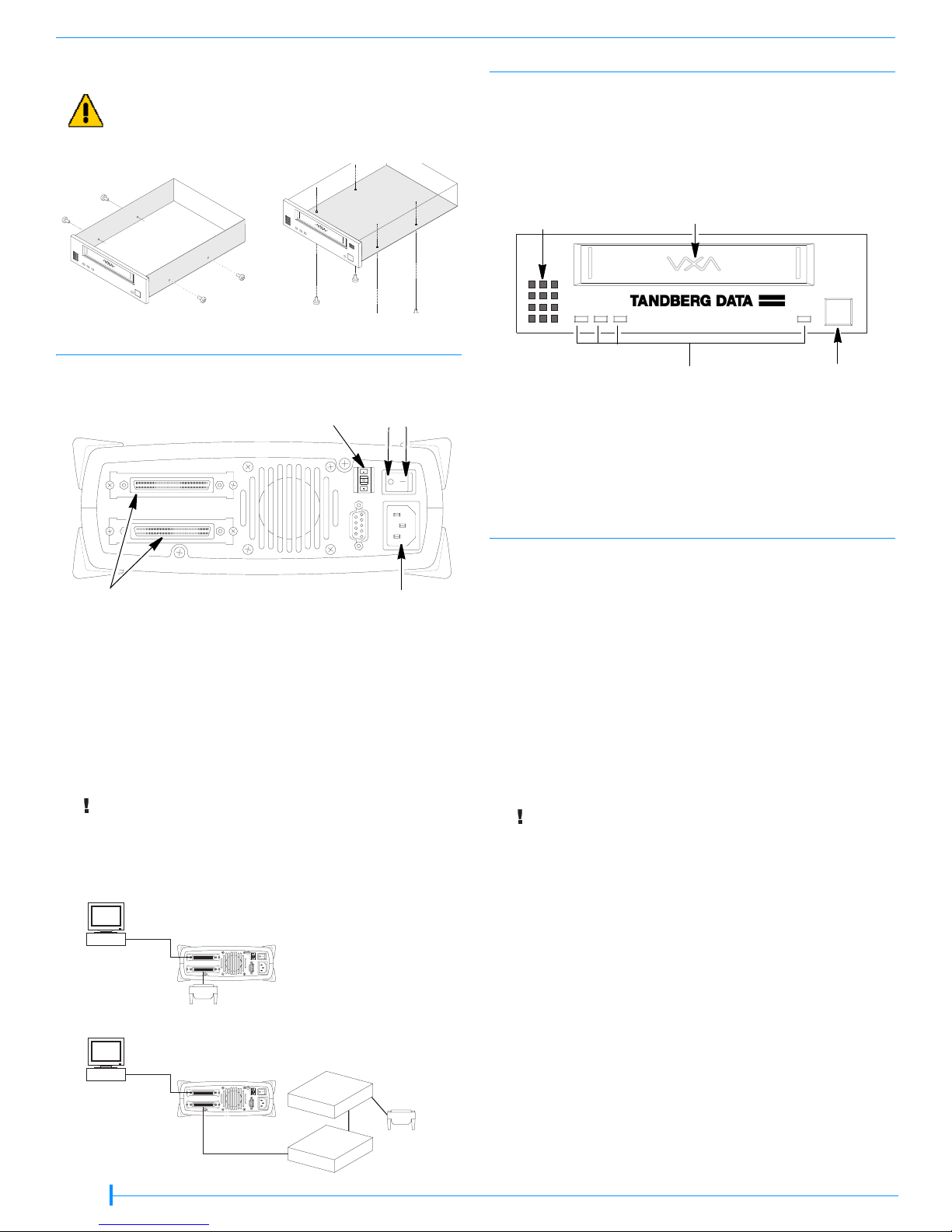
8. Using the Phillips screws provided with the tape drive, secure the tape
drive in one of the screw-mounting configurations, as shown below.
Use only the Phillips screws provided with the drive.
Caution
Side mounting
Bottom mounting
4| POWERING ON AND TESTING THE DRIVE
1. For the internal model: Power on the host computer.
For the external model: Press the power switch on the back of the tape
drive, then power on the host computer.
The LEDs on the front scroll sequentially right to left, then left to right in
amber and green. LED 4 illuminates in red and green. When the sequence
is complete, LED 4 illuminates in green.
3
3
3| INSTALLING THE EXTERNAL TAPE DRIVE
When installing the external model of the drive, refer to the following
illustration for the location of back-panel components.
SCSI ID switch
SCSI
connectors
1. Set the SCSI ID by using the + and – tabs on the SCSI ID switch. The drive
is shipped with a default ID of 11. Select a SCSI ID for the drive which is
unique. The host bus adaptor and any peripherals attached to the SCSI bus
must all be set to unique SCSI IDs. (The terminator does not use a SCSI ID.)
2. Connect a SCSI cable from the host computer to one of the SCSI
connectors. Check the connector for bent or pushed in pins before
connecting to the tape drive.
3. If the drive is at the physical end of the SCSI bus, install a terminator on the
unused SCSI connector. If there is another device on the bus after the
drive, make sure the last device is terminated.
Both VXA-172 and VXA-320 tape drives require an
Important
4. Connect the power cord to the back of the drive.
Ultra 3 or LVD 160 terminator to function properly on
the SCSI bus. An inadequate terminator will result in
various SCSI bus issues, including bus hangs and
Read/Write failures.
To SCSI Adapter
Computer
{
The tape drive is the
last device on the
SCSI bus.
Off On
AC power
connector
Ventilation
holes
Front view (internal model shown)
Door
3
123
Status LEDs
2. Insert a VXAtape cartridge in the drive door. The tape drive loads the tape
in less than one minute (LED #2 flashes green). When LED #2 stops
flashing, and is solid green, the drive is ready for read and write operations.
3. Perform a small write and read operation. Install VXATool and use it to run
a write/read test. VXATool is available for several operating systems. Check
the Support section of Tandberg's web site, www.tandberg.com, for the
VXATool for your operating system.
5| PREPARING FOR BACKUP
Select and install a backup application.
Software compatibility information is available at: www.tandberg.com.
If your backup application does not support the VXA-172 or VXA-320
(VXA-3) tape drive, you can use VXATool to change the product
identification information (Inquiry String) that the tape drive returns to the
software. Changing the tape drive’s identification information does not
affect the tape drive’s speed or capacity. For instructions on using VXATool
to change the tape drive’s Inquiry String, refer to the help or readme file
provided with VXATool.
Additional information is available at www.tandberg.com.
The CD included with the tape drive provides device drivers for use with
Windows operating systems.
The most current version of these drivers is available at:
www.tandberg.com.
Do not install these drivers unless you are using the Windows
Important
Note: Driver installation for the tape drive may not be necessary and
depends on the backup application that you use in your system. Refer to
the installation instructions for your backup application for verification.
Driver installation information is available at: www.tandberg.com.
Contact your software provider with questions regarding the software
installation, configuration, and operation.
native backup application or unless your backup application
instructs you to do so.
4
Eject button
Terminator
Another peripheral is
the last device on the
SCSI bus.
To SCSI Adapter
Computer
Terminated
SCSI D
evice
SCSI Device
2 of 4
{
Terminator
Page 3

Quick Reference—VXA-172 and VXA-320 (VXA-3) LEDs
(Keep this sheet close to your tape drive for reference)
Operation LED Pattern LED #1 LED #2 LED #3 LED #4
Operational Conditions
Power- on self-test LEDs illuminate sequentially
No tape loaded Off Off Off Green
Interface activity; (LED 4 may flash with other
LED operations)
Off Off Off Flashing Green
Tape loading or unloading Off Flashing Green Off Off
Tape ready; idle Off Green Off Off
Reading Off Off Green Off or Flashing Green
a
Writing Off Amber or Green
b
Amber Off or Flashing Green
Space forward Off Off Flashing Green Off
Space reverse or rewinding Flashing Green Off Off Off
Cleaning in process Flashing Green Off Flashing Green Off
Service Notification
Cleaning required Off Flashing Amber Off Off
Cleaning tape used up Off Flashing Green/Amber Off Off
Recoverable error
Unrecoverable error
Factory service requiredd
c
c
Amber Green Amber Off or Green
Amber Off Amber Off or Green
Flashing Green or Amber Flashing Red
Broken tape Flashing Green/Amber Off Flashing Green/Amber Green
Format recovery
Temperature too high in tape path
Boot Block Mode
e
f
g
Off Off Flashing Green/Amber Green
Off Off Off Flashing Orange
Flashing Green Flashing Amber Flashing Orange Flashing Green
Self Test
Self-test running Fast scrolling green Off or Flashing Green
Self-test passed Green Green Green Off
Self-test failedh
Amber Amber Amber Off
Firmware Load
Loading firmware Flashing Amber Flashing Green Flashing Amber Orange
Loading firmware Flashing Green/Amber Flashing Green/Amber Flashing Green/Amber Orange
KEY: Flashing LEDs = On = Off =
a
For the power-on self-test, the LEDs scroll sequentially right to left then left to right in amber and green. LED 4 illuminates in red and green. When POST is
completed, LED 4 is illuminated in green.
b
When LED 2 is amber, hardware compression is enabled. When LED 2 is green, hardware compression is disabled.
c
Retry the operation with another tape, making sure that the tape is not written in VXA-1 format. If the problem persists, try power cycling the drive to clear
the error.
If you cannot resolve the problem yourself, contact Tandberg Technical Support (see www.tandberg.com). To capture a log of a problem, use
VXATool, which is available as a free download from www.tandberg.com.
d
You may need to return the tape drive for service; contact Tandberg Technical Support. To get a log of the problem, use VXATool, which is available as a
free download from www.tandberg.com.
e
The tape was written without a valid end-of-data mark, which often occurs if you power-down the tape drive while the tape drive was writing. The tape
drive will perform a format recovery, which involves reading the data to determine where the end of data is located. This may take as long as 2 to 3 hours.
f
Refer to the VXA-172 Tape Drive Product Manual or the VXA-320 Tape Drive Product Manual, Chapter4, the “LED 4 is Flashing Orange” section for
troubleshooting information.
g
If the tape drive is in Boot Block Mode, try power cycling the drive. If it remains in Boot Block Mode, load new firmware. VXA-172 and VXA-320 (VXA-3)
firmware is available at www.tandberg.com.
h
If a self-test fails, clean the tape drive with a VXAtape cleaning cartridge. If the failure still occurs, try a new tape.
3 of 4
Page 4

ADDITIONAL INFORMATION
CONTACT TANDBERG DATA
For information about operating the tape drive and specifications for the
drive, refer to the VXA-172 Product Manual or the VXA-320 (VXA-3)
Product Manual at www.tandberg.com.
Register your tape drive online at www.tandberg.com. If you need to speak
with a Customer Service representative, see Tandberg’s web site at
www.tandberg.com.
DATA CARTRIDGE COMPATIBILITY
This table shows the cartridge compatibility for the VXA-172 and VXA-320
tape drives. You can purchase data cartridges and cleaning cartridges from
Tandberg. Use only cartridges designed specifically for VXA tape drives.
VXA Tape
Drive
VXA-172
VXA-320
(VXA-3)
Notes: The VXA-172 tape drive does not support VXAtape V6, V10, V17,
V23, or X23.
The VXA-320 (VXA-3) tape drive does not support VXAtape V6,
V10, or V17.
To clean your tape drive, use only Tandberg VXAtape Cleaning
Cartridges (20+uses).
*V23 Media is dicontinued
Cartridge
Compatibility
(Tandberg VXAtape)
X10 120 86 GB native capacity
X6 62 40 GB native capacity
X23*
V23
X10 120 86 GB native capacity
X6 62 40 GB native capacity
Length
(m)
(172 GB compressed 2:1)
(80 GB compressed 2:1)
230 160 GB native capacity
(320 GB compressed 2:1)
(172 GB compressed 2:1)
(80 GB compressed 2:1)
Capacity
TANDBERG DATA ASA
P.O. Box 134 Kjelsås
N-0411 OSLO, NORWAY
Phone + 47 22 18 90 90
Telefax + 47 22 18 95 50
www.tandberg.com
4 of 4
 Loading...