

Page 1

ST.US.E10137.2
USER GUIDE
Voyager E5784 and E5788
HD DSNG Encoder
Software Version 3.6.0
(and later)
E5784/E5788 Encoder
ENGLISH (UK)
www.tandbergtv.com
Page 2

Voyager E5784 and E5788 HD DSNG Encoder
Trademarks
Dolby® / Dolby® Digital / AC-3® are registered trademarks of Dolby
Laboratories Licensing Corporation.
Customer Services
Europe, Middle East Tel: +44 (0) 23 8048 4455
and Africa: Fax: +44 (0) 23 8048 4467
support@tandbergtv.com
Americas: Tel: +1 (321) 308 0470
fieldservice-americas@tandbergtv.com
China: Tel: +86 10 6856 0260 (Beijing)
Tel: +852 2530 3215 (Hong Kong)
fieldservice-asia@tandbergtv.com
Australia/NZ: Tel: +612 8923 0450
fieldservice-australia@tandbergtv.com
Internet Address: http://www.tandbergtv.com
Technical Training
International: Tel: +44 (0) 23 8048 4229
Fax: +44 (0) 23 8048 4467
training@tandbergtv.com
This document and the inf o rmation contained in
it is the property of TANDBERG Television Ltd
and may be the subject of patents pending and
granted. It must not be used for commercial
purposes nor copied, disclosed, reproduced,
stored in a retrieval system or transmitted in
any form or by any means ( electronic,
mechanical, photocopying, recording or
otherwise), whether in whole or in part, without
TANDBERG Television’s prior written agreement.
© 2004-2005 TANDBERG Television Ltd.
All rights reserved.
2
Issue 2 first published in 2005 by:
TANDBERG Television Ltd
Registered Address:
Unit 2 Strategic Park, Comines Way,
Hedge End, Southampton,
Hampshire,
SO30 4DA
United Kingdom
Registered Company Number 03695535
Page 3

Voyager E5784 and E5788 HD DSNG Encoder
Contents
1 Who Should Use This User Guide?.................................................5
1.1 What Equipment is Covered by This User Guide? .................................. 5
1.2 Hardware and Software Options......................................................... 6
2 Installing the Equipment...............................................................8
2.1 Introduction.................................................................................... 8
2.2 Operating Voltage............................................................................ 8
2.3 Power Cable and Earthing ................................................................. 8
2.4 Power Supply Stand-by Switch...........................................................9
2.5 Connecting Up the Basic Encoder ..................................................... 10
2.6 Connecting the Encoder to the Power Supply ..................................... 12
3 Operating the Equipment From t he Front Panel........................... 14
3.1 Introduction.................................................................................. 14
3.2 Establishing Local Control................................................................ 14
3.3 Navigating the Menus..................................................................... 15
4 Typical Operation and Setting of Parameters...............................17
4.1 Select Syntax................................................................................ 18
4.2 Load Default Configuration/Restore Factory Defaults........................... 18
4.3 Set the Remote Control Options....................................................... 18
4.4 Set the Mux Options....................................................................... 19
4.5 Set the Video Options..................................................................... 19
4.6 Set the VBI Options........................................................................ 20
4.7 Set the Audio Options..................................................................... 22
4.8 Set the Data Options...................................................................... 23
4.9 Set the Output Options................................................................... 23
4.10 Configuring Option Cards ................................................................ 23
4.11 Satellite Modulator Control .............................................................. 23
4.12 Configuring the Encoder for Minimum Bit-rate.................................... 24
5 Typical Configurations ................................................................26
5.1 Single Channel DSNG Link............................................................... 26
5.2 Multichannel DSNG Link.................................................................. 27
3
Page 4

Voyager E5784 and E5788 HD DSNG Encoder
List of Figures
Figure 2.1: Stand-by Switch ..................................................................... 9
Figure 2.2: IF Rear Panel Component Parts and Connectors......................... 10
Figure 2.3: L-band Rear Panel Component Parts and Connectors.................. 10
Figure 3.1: Input Monitor in SD............................................................... 14
Figure 3.2: Summary Screen .................................................................. 15
Figure 3.3: Keypad and Display Functions................................................. 15
Figure 3.4: Accessing Inscriptions on the Keypad....................................... 15
Figure 3.5: Functions Associated With Softkeys ......................................... 16
Figure 4.1: Menu Structure..................................................................... 17
Figure 5.1: Block Diagram – One Stage of Remultiplexing........................... 27
List of Tables
Table 1.1: Equipment Model Descriptions.................................................... 5
Table 1.2: Hardware Options .................................................................... 6
Table 1.3: Software Options ..................................................................... 6
Table 2.1: Types of Connector................................................................. 11
Table 2.2: Fuse Type and Rating ............................................................. 13
4
Page 5
Voyager E5784 and E5788 HD DSNG Encoder
1 Who Should Use This User Guide?
This User Guide is written for operators/users of the E5784 and E5788
HD DSNG Encoders to assist in installation and operation. It is not
intended to be a detailed source of information. This can be found in the
Reference Guide companion document which is issued on CD.
WARNING
Do not remove the covers of this equipment. Hazardous voltages are
present within this equipment and m a y be exposed if the covers are
removed. Only TANDBERG Television trained and approved service
engineers are permitted t o service this equipment.
CAUTION
Unauthorised maintenance or the use of non-app roved replacements m a y
affect the equipment specification and invalidate any warranties.
1.1 What Equipment is Covered by This User Guide?
Table 1.1: Equipment Model Descriptions
Model Number Marketing Code Description
E5784 M2/VOY/E5784-IF MPEG-2 HD DSNG Encoder with 4:2:0
E5784 M2/VOY/E5784-LBAND MPEG-2 HD DSNG Encoder with 4:2:0
E5788 M2/VOY/E5788-IF MPEG-2 HD DSNG Encoder with
E5788 M2/VOY/E5788-LBAND MPEG-2 HD DSNG Encoder with
video encoding and IF out put satellite
modulator.
video encoding and L-Band output
satellite modulator.
4:2:0/4:2:2 video encoding and IF
output satellite modulator .
4:2:0/4:2:2 video encoding and L-Band
output satellite modulator .
5
Page 6

Voyager E5784 and E5788 HD DSNG Encoder
1.2 Hardware and Software Options
See Table 1.2 and Table 1.3 for a list of hardware and software options
available with the Encoder. Detailed information is in the Reference
Guide.
Table 1.2: Hardware Options
Marketing Code Description
Daughter Card Options
M2/EDCOM2/BISS BISS1 scrambling option - Mode 0, 1 and BISS-E
Hardware Options
M2/EOM2/AUDLIN2 Additional Audio + Linear PCM
M2/EOM2/DAT Data Input Option
M2/EOM2/REMUX Remux Option Module
M2/EOM2/ASI-OPT SMPTE 310 (SSI) and ASI Optical Outputs
M2/EOM2/SSI-US SMPTE 310 (SSI) Outputs
M2/EOM2/ATMS155MM
M2/EOM2/ATMS155SM STM-1 OC3 Monomode Physical Interface Module
M2/EOM2/ATMS34 PDH/E3 Module
M2/EOM2/ATMS45 PDH/DS3 Module
M2/EOM2/ATMS155E STM-1 Electrical Module
M2/EOM2/G703 G.703 Output Interface Card
M2/EOM2/IP IP Output Card
M2/EOM2/GPI GPI Card
STM-1 OC3 Multimode Physical Interface Module
(SDH STM-1/SONET STS-3c Multimode Optical)
(SDH STM-1/SONET STS-3c Monomode Optical)
6
Table 1.3: Software Options
Marketing Code Description
M2/ESO2/NR Noise Reduction - three levels of professional-grade
M2/ESO2/VBR Reflex and VBR - automatic variable bit-rate at a fixed
M2/ESO2/422 MPEG-2 422P@ML - for professional editing quality
1
BISS is implemented according to Tech 3290 March 2000 and BISS-E is implem ented
according to Tech 3292 April 2001.
adaptive noise reduction.
quality setting for optimum bandwidth usage in
stand-alone or Reflex statistical multiplexing modes.
pictures, 1.5 Mbit/s to 50 Mbit/s.
Page 7

Voyager E5784 and E5788 HD DSNG Encoder
Marketing Code Description
M2/ESO2/RAS RAS (Remote Authorisation System) - allows material
M2/ESO2/ACON Auto Concatenation - aligns the Encoder to the
M2/ESO2/AC3 Dolby Digital (AC-3) - enables Dolby AC-3 stereo
M2/EOS2/SM38PSK 8PSK Modulation.
M2/EOS2/SM316QAM 16QAM Modulation.
M2/EOS2/LSYM Low symbol Rate Capability.
M2/ESO2/DVB-MHP MHP Timing Events
M2/ESO2/DTS DTS Audio
M2/ESO2/525VBIDATA NABTS and GEMSTAR 2.0 VBI extraction
M2/ESO2/SCTE-35
HD Options
M2/ESO2/HDNR HD Noise Reduction.
M2/ESO2/HDVBR Reflex and VBR - automatic variable bit-rate at a fixed
M2/ESO2/HD422 MPEG-2 422P@ML - for professional editing quality
2
to be protec ted from illegal viewing using TANDBERG
Television’s proprietary scrambling system.
previous Encoder’s GOP structure to significantly
reduce coding artefacts caused by successive coding
and decoding.
encoding.
Licence key for Splice Points
quality setting for optimum bandwidth usage in standalone or Reflex statistical multiplexing modes.
pictures.
2
M2/ESO2/SCTE-35 only available when M2/EOM2/GPI purchasable option installed.
7
Page 8
Voyager E5784 and E5788 HD DSNG Encoder
2 Installing the Equipment
2.1 Introduction
For best performance and reliability follow the instructions for site
requirements and installation in the Reference Guide and only use
installation accessories recommended by the manufacturers.
2.2 Operating Voltage
AC models are fitted with a wide-ranging power supply. It is suitable for
supply voltages of 100-120 Vac -10% +6% or 220-240 Vac -10% +6%
at 50/60 Hz nominal.
CAUTION
This product should be operated only from the type of power source
indicated on the marking label. If you are not sure of the type of power
supply to your business, consult a qualified electrical engineer or your
local power company.
NOTE
Refer to the Reference Guide for details of the colour codes used on
the mains leads.
See Table 2.2 for fuse information and also the Reference Guide for a
full power supply specification.
2.3 Power Cable and Earthing
Check that the power cable is suitable for the country in which the
Encoder is to be used.
WARNINGS
1. The Technical Earth is not a Protective earth for electric s hock
protection.
2. This unit m ust be correctly earthed through the m o ulded plug
supplied. If the local mains supply does not have an earth
conductor do not connect the unit. Contact Customer Servi c es
for advice.
3. Before connecting the unit to the suppl y , c heck the supply
requirements in Annex B o f the Reference Guide.
8
Page 9
Voyager E5784 and E5788 HD DSNG Encoder
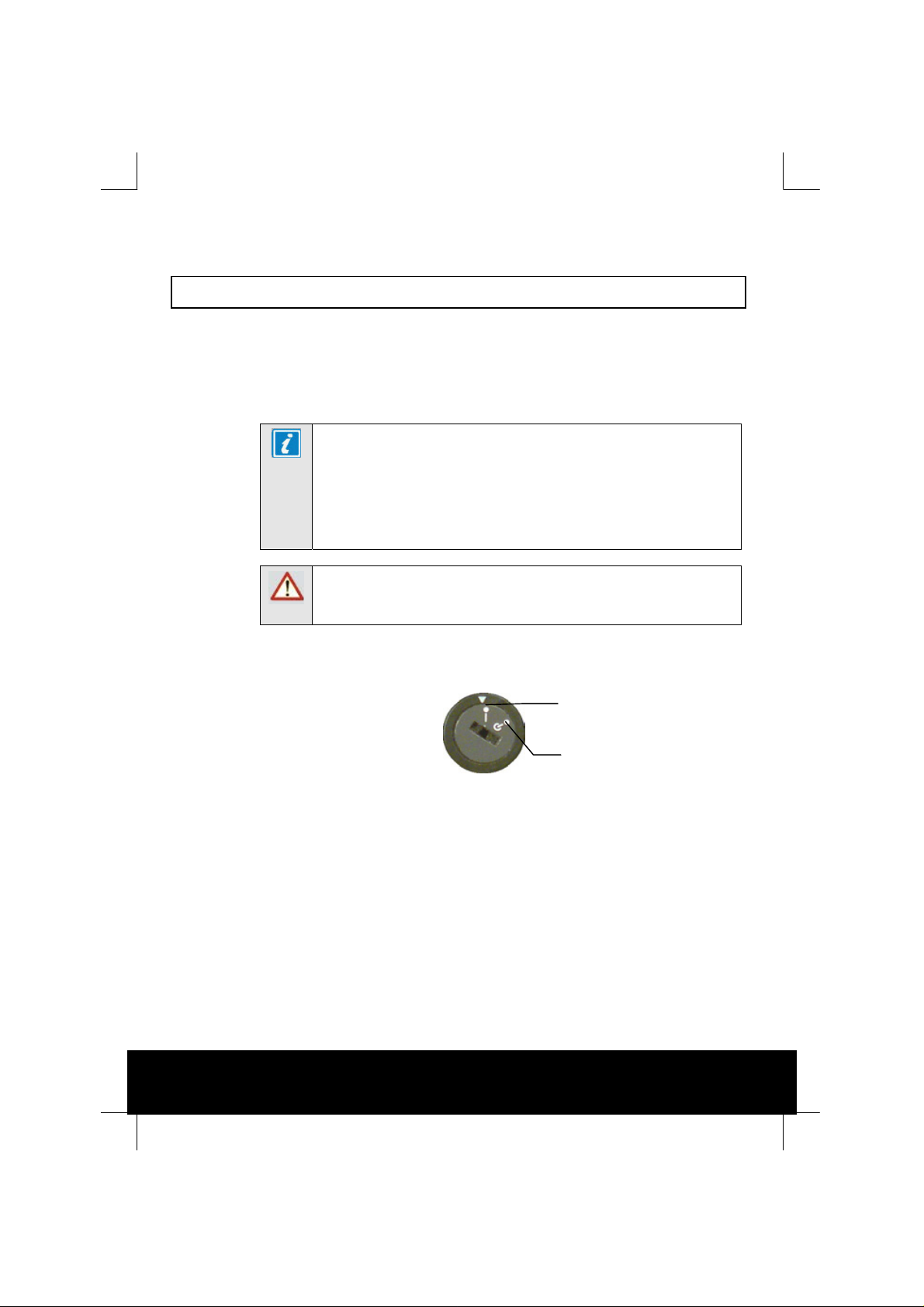
2.4 Power Supply Stand-by Switch
This switch puts the Encoder into stand-by mode. It powers down the
supply rails of the display and internal circuits within the unit. The
switch type avoids accidental powering-down of the Encoder. For normal
use, using a screwdriver, ensure that the I is always at the top (see
Figure 2.1).
NOTES
1. This product should be operated only from the type of power
source indicated on the marking label.
2. If you are not sure of the type of power supply to your
business, consult a qualified electrical engineer or your local
power company.
WARNING
This is NOT a mains switch and will not isolate the Encoder from the
power supply. Disconnect the power cord to isolate the unit.
On position
Stand-by position
Figure 2.1: Stand-by Switch
9
Page 10

Voyager E5784 and E5788 HD DSNG Encoder
2.5 Connecting Up the Basic Encoder
Always use the specified cables supplied for signal integrity and
compliance with EMC requirements (see the Reference Guide).
Only those connectors used are labelled in Figure 2.2, Figure 2.3 and
described in Table 2.1.
Alarm
RS-422
Data
Option Slot
RS-232
Data
Remote
Control
Ethernet
1 and 2
ASI
Outputs
HD SDI Input
IF Out Main
Figure 2.2: IF Rear Panel Component Parts and C onnectors
Alarm
RS-422
Data
RS-232
Data
Remote
Control
Ethernet
1 and 2
ASI
Outputs
H Sync
SDI In
IF Out Monitor
H Sync
SDI In
Composite
Video
Option Slot
Composite
Video
Audio In and
Audio Reference
Out
Audio In and
Audio Reference
Out
Technical
Earth
Technical
Earth
10
Option Slot
Option Slot
HD SDI Input
L-Band
In
L-Band Out
Main
L-Band Out
Monitor
Figure 2.3: L-band Rear Panel Component Parts and Connectors
Page 11

Voyager E5784 and E5788 HD DSNG Encoder
Table 2.1: Types of Connector
Type of Connector Description
W BNC connector provides a serial digital video input
SDI IN
HD SDI INPUT
COMP VIDEO
H SYNC
Audio In
ASI OUT 1, 2 and 3 A 75
Ethernet #1 and #2 An 8-way, RJ-45 connector provides a 10BaseT Ethernet
RS-232/RS-485
Control
Alarm If required, connect an external status monitoring device
RS-232 RS-232 data is available on the Base Board and the
RS-422 A 15-way, D-type female connector provides an RS-422
A 75
to the unit. This input is terminated in 75
W BNC connector prov ides an HD serial digital video
A 75
input to the unit. This input is terminated in 75
W BNC connector provides a high quality analogue
A 75
video input to the unit.
Optional - Studio Black and Burst should be fed to the
75
W BNC connector (H SYNC). This genlocks the
Encoder to the Studio system. This method may be
required with some audio formats, or for locking
Encoders to an evolution 5000 Multiplexe r.
The 15-way, D-type male connector is used in different
ways according to the audio input and the encoding
configuration selected.
The connector provides two stereo pairs which may be
independently config ured as either analogue or digital.
The left channel is used to input digital audio.
The Encoder is supplied with a break-out cable which
plugs into this connector, and provides a more
convenient means of connecting the audio signals via
five connectors. There are four XLR female connectors,
with the fifth cable being a BNC which provides an
AES/EBU 75
the unit is connected to an external Dolby Digital
Encoder.
Encoder. Connect the Multiplexer or Modulator ASI cable
to the appropriate ASI OUT connector, using good
quality 75
interface for communications with the TDC/MEM for
control and monitoring. The Encoder has a single
switched Ethernet channel. Ethernet#1 is selected as
default at power-up. If a carrier is not detected on
Ethernet#1 then the input switches to Ethernet#2. This
gives a redundant Ethernet control via two hubs.
A 9-way, D-type male connector provides an
RS-232/RS-485 port for remote control of the Encoder.
This connector is wired as a DTE.
to the ALARM connector. A 9-way, D-type male
connector provides an alarm relay interface which can
be used to send a signal to remote equipment.
option module M2/EOM2/DAT.
synchronous, serial communications data input interface.
W digital reference output. This is for when
W BNC connector provides the output from the
W coaxial cable (for example, BBC PSF 1/3).
W.
W.
11
Page 12

Voyager E5784 and E5788 HD DSNG Encoder
Type of Connector Description
Technical Earth Connect the Encoder's Technical earth to a suitable
IF Version
IF Out Main A 75
IF Out Mon A 75
L-Band Version
L-Band In A 50
L-Band Out (Main) A 50
L-Band Out (Mon) A 75
point.
W BNC connector provides t he main satellite
modulator IF output.
W BNC connector provides t he a satellite modulator
IF output. which is approximately –20dB relative to IF
Main.
W SMA connector provides the L-Band input, which
is summed with the modulator output.
W SMA connector provides the main satellite
modulator L-Band output. This output can also provide
+24V DC at up to 500 mA to power an up-converter.
Both models can also provide a 10 MHz reference
frequency output.
W F-type connector provid es the a satellite
modulator L-band output. which is approximately –30dB
relative to the main output.
NOTE
Refer to the Reference Guide for all power supply, fuse, safety, EMC
information and operating conditions.
2.6 Connecting the Encoder to the Power Supply
WARNINGS
1. Do not overload wall outlets and extension cords as this can
result in a risk of fire or electric shock.
2. As no mains switch is fitted to this unit, ensure the local power
supply is switched OFF before connecting the supply cord.
3. The Encoder is not fi tted with an on/off switch. Ensure that the
socket-outlet is installed near the equipment so that it is easily
accessible. Failure to isolate the equipment p ro perly may cause
a safety hazard.
12
Page 13

Voyager E5784 and E5788 HD DSNG Encoder
Connect the Encoder to the power supply as follows:
> Power Supply
Ensure the power supply is isolated and switched off.
> Encoder
Ensure the correct fuse type and rating has been fitted to both the
equipment and the power cable.
> Supply Cord
Connect the lead to the Encoder input connector and then to the
power supply. Switch on the power supply.
Table 2.2: Fuse Type and Rating
Power Supply Fuse Type and Rating
100-120 Vac / 220-240 Vac IEC/EN 60127-2 Sheet 5
Bussmann S505/Littelfuse 215
5 A 250 V T HBC
13
Page 14

Voyager E5784 and E5788 HD DSNG Encoder
3 Operating the Equipment From the Front Panel
3.1 Introduction
The front panel display and keypad may be used to configure, control
and monitor the Encoder when an external control system is not used.
3.2 Establishing Local Control
3.2.1 Input Monitor / Keyboard Lock
At power-on the Encoder runs through a boot sequence (boot time
without any option modules is approximately 45 seconds). An initial
Input Monitor screen is shown.
Key icon, show n in the
unlocked posit ion.
14
Figure 3.1: Input Monitor in SD
The softkeys can be locked out to prevent inadvertent operation (see
the key icon in Figure 3.1). Press the softkey adjacent to the key icon.
This shows the Keyboard Lock screen. Press the Yes softkey to disable
the softkeys. They are all disabled with the exception of Unlock.
To enable and restore the softkey functions, press the Unlock softkey.
This shows the Keyboard Lock screen. Press the Yes softkey.
Page 15

3.2.2 Summary Screen
(
A
Voyager E5784 and E5788 HD DSNG Encoder
On or Off Air.
Indicates whether or not the mux
On Air option is set to on or off.
Clear or Scramble d.
Indicates whether or not the
Figure 3.2: Summary Screen
3.3 Navigating the Menus
3.3.1 Moving Through the Menu Screens
Each softkey on each side of
the display is used to
access, select and
sometimes amend the menu
item associated with it.
Where there is a +/sign associated with a
softkey, this scroll s
through a set of
options.
This gives quick acce ss
to the Configurations
menu
Press More softkey to
access the Advanced
(Top Level) menu
This keypad is used to
amend the menu option
which has been selecte d
unless indicated otherwise).
Figure 3.3: Keypad and Display Functions
3.3.2 How to Use the Keypad
Press the softkey once to have a
2 appear on the displ ay scre e n
Press the softkey twice in rapid
succession for an A to appear on
the display screen
2
BC
Figure 3.4: Accessing Inscriptions on the Keypad
Press the softkey three ti m e s in rapid
succession to have a B appear on the
display screen
Press the softkey four time s in rapid
succession to have a C appear on
the display screen
15
Page 16

Voyager E5784 and E5788 HD DSNG Encoder
3.3.3 How to Use the Functions Associated with Softkeys
The following display screens show the different functions associated
with the options.
Press Left and Right to
move the underscore to
the next letter that you
want to change.
Press Ins to insert a
space where the
underscore is.
Press Del to delete
where the
underscore is.
On Air / Off Air indicates
whether the mux On Air
option is se t to on or off.
Softkeys mean those at the side of the
screen and those on the keypad.
Figure 3.5: Functions Associated With Softkeys
NOTE
A black diagonal cross enclosed by a white circle ( ) means that
the Encoder is under remote co ntro l and the user does not have
access to change that parameter.
Scramble means that
scrambling is enabled.
Clear means that it is n ot.
Press + and - to
scroll through the
choices in the option.
Press Enter to accept
the option choice.
Press Quit to revert to
previous menu.
16
Page 17

Voyager E5784 and E5788 HD DSNG Encoder
4 Typical Operation and Setting of Parameters
Summary
Screen
Ops
Cfgs....
More....
Quit
Advanced
Menu
Setup....
Errors....
Diagnostics....
Ops
Configs....
Quit
Front Panel
Diagnostics
Menu
Config
Menu
Errors
Menu
Setup
Menu
System....
Video....
Audio....
Data....
Output....
Mux....
Quit
System
Menu
Service In fo....
Remote Control....
General....
Advanced....
Mbd Services....
Build....
Quit
Video
Menu
Video Source....
Video Encoder....
VBI....
Audio
Menu
Audio A....
Audio B....
Audio XLR....
Audio Langua ges
Data
Menu
Data A - RS232....
Data B - RS422....
Output
Menu
Output Form at
Delivery Descriptor....
Sat Modulator....
Mux
Menu
Mux....
Figure 4.1: Menu Structure
17
Page 18

Voyager E5784 and E5788 HD DSNG Encoder
Refer the following steps for a typical set-up. See Figure 4.1 for the
menu tree structure and Section 4.1 onwards on how to navigate the
menus. For more detailed information or parameters not ment ioned
refer to the Reference Guide.
> Select the syntax.
> Optional - load a default configuration and amend if necessary or
restore the factory defaults. Refer to Section 5 for examples of
typical configurat ions.
> Set the remote control options.
> Set the mux options.
> Set the video options.
> Set the audio options.
> Set the data options.
> Set the Satellite modu lator options.
4.1 Select Syntax
Navigate to the Service Info Menu and select the Syntax option.
Choose DVB or ATSC, as required. For DSNG applications DVB syn tax is
usually used. The service information for the service can then be set in
the Service Info Menu.
4.2 Load Default Configuration/Restore Factory Defaults
From the Summary screen navigate to the Configs Menu. Select Load
Active Config and choose one of the configurations . Amend the
parameters as necessary.
4.3 Set the Remote Control Options
If the Encoder is to be controlled via its Ethernet interface the unit's IP
address and associated parameters must be set in the Remote Control
Menu.
Navigate to the Remote Control Menu. Select the following options:
> IP Address Option – enter or change the IP address of the unit.
> Change other options as required.
18
Page 19

4.4 Set the Mux Options
Navigate to the Mux Menu. Select the following options:
> Packet Length Option – if the satellite modulator is selected as
the output, then the packet length is forced to be 204 bytes.
> On Air – set to On to send the output of the Encoder to the
Multiplexer.
> Bit-rate (188) / Bit-rate (204) Options – select the required
bit-rate.
NOTE
If the Packet Length option is set to 188 by tes then only the Bitrate (188) option is displayed. If the Packet Length option is set to
204 bytes then both the Bit-rate (188) and Bit-rate (204) options
are displayed.
4.5 Set the Video Options
Navigate to the Video Menu and select the Video Encoder Menu to
configure the video input to the Encoder. Select the following options:
Voyager E5784 and E5788 HD DSNG Encoder
> Profile\Level Option – select MP@ML, 422P@ML, MP@HL or
422P@HL.
NOTE
This option is al ways MP@ML or MP@HL on an E5784.
19
Page 20

Voyager E5784 and E5788 HD DSNG Encoder
> Compression Mode – select the required compression mode.
Standard is the default mode. The various seamless modes allow
the bit-rate to be changed, over a defined range, without a break in
transmission. The low delay modes use various techniques to
reduce the encoding delay, but picture quality may reduce (see the
Reference Guide for more details).
NOTE
In SD changing compression mode can change the GOP structure
and length.
> Bit-Rate – select the required video bit-rate. This defaults to the
maximum possible bit-rate given the current mux bit-rate set, and
the bit-rates set for the other elements such as audio and data.
NOTE
In SD, high bit-rates in low resolutions cannot alway s generate
sufficient bits to matc h the requested bit- rate. How ev er, a valid
picture is still produced.
> Exit the Video Encoder Menu and then select the Video Source
Menu to configure the following option.
> Video Input – select the video input required. The video input
options depend upon the profile selected. If the selected input is SD
SDI, the frame rate must also be set. For HD format s choose the
correct input (see the Reference Guide for details).
4.6 Set the VBI Options
Navigate to the Video Menu and select the VBI Menu. The options
available depend on whether the video source is 625 lines, 25 Hz or
525 lines, 29.97 Hz.
VBI In Picture (SD only) - if the video profile level is 422P@ML, then a
VBI In Picture option is available. This transmits the VBI lines as part
of the picture. They will suffer some distortion, and so this is not
suitable for all VBI types, e.g. Video Index.
20
Page 21

Voyager E5784 and E5788 HD DSNG Encoder
NOTES
1. Requires up to 3 Mbit/s of v ideo bit-rate to carry this additio nal
information.
2. 3:2 pull d o wn cannot be used when using thi s o p tion.
VBI Options (625 lines, 25 Hz) – in SD the Encoder can extract a
maximum of eight VBI lines per field on the SD inputs. However this
limit does not apply to Teletext. The possible VBI lines are 6 – 23 and
318 – 335.
In SD the possible VBI types are; Vertical Interval Time Code (VITC),
Video Index, Teletext System B, Inverted Teletext, Wide Screen
Signalling, and Video Programming System (VPS).
In HD Teletext can be extracted from the SD inputs and put into the
stream on its own PID.
> Teletext - to enable the processing of Teletext select the following
options:
+ Teletext All Lines – set to On to enable Teletext System B
extraction from all VBI lines.
+ Teletext PID – assign the PID to be used to carry the extracted
Teletext data.
+ VBI Line – select individual VBI lines to either turn Teletext
extraction off for that line, or to change the VBI type.
> Other VBI types (SD only) - to enable the processing of VBI other
than Teletext select the following options:
+ VBI on PID – set to On to enable the extracted VBI data to be
carried on a separate PID.
+ VBI PID - assign the PID to be used to carry the VBI data.
+ VPS (Line 16) – set to On if VPS is to be extracted from
line 16.
+ WSS (line 23) – set to the appropriate WSS type, if WSS is to
be extracted from line 23. The WSS types are ETSI 300 294, or
WSS-AFD.
+ Auto Detect VITC – set to On if the Encoder is required to
automatically detect the presence of VITC and extract it. In HD
the timecode is extracted according to SMPTE RP188 from the
HD SDI.
+ VBI Lines – if necessary, select individual VBI lines to set the
VBI type that the Encoder should extract from that line.
21
Page 22

Voyager E5784 and E5788 HD DSNG Encoder
VBI Options (525 lines, 29.97 Hz) - in SD the Encoder can extract a
maximum of eight VBI lines per field. The possible VBI types are;
Vertical Interval Time Code (VITC), Video Index, Closed Caption,
Neilson AMOL 1, and Neilson AMOL 11.
To enable the processing of VBI select the following options:
> VBI on PID – set to On to enable the extracted VBI data to be
carried on a separate PID.
> VBI PID - assign the PID to be used to carry the VBI data.
> Auto Detect VITC – set to On if the Encoder is required to
automatically detect the presence of VITC and extract it. In HD the
timecode is extracted according to SMPTE RP188 from the HD SDI.
> VBI Lines – select individual VBI lines to set the VBI type that the
Encoder should extract from that line (SD only).
> Closed Captions – set to the required source of closed caption
data. The options are; video line 21, video line 21 and line 284,
SMPTE 333M and SMPTE 334.
> CC Format – select the required closed caption format, the default
is ATSC, and this is the required setting for EIA-708B compliant
closed captions.
> SMPTE 333M Port – if the closed caption source has been set to
SMPTE 333M, then the Encoder’s RS-232 port through which the
data is to be input must be selected.
> SMPTE 334 CC can be extracted from the HD-SDI.
For more details regarding setting up the Encoder’s closed caption
options see the Reference Guide.
4.7 Set the Audio Options
The standard Encoder can process two stereo pairs, but up to four can
be processed with the addition of audio option cards. All the audio
inputs are configured in a similar manner.
Navigate to the Audio Menu. Select the following options:
> Source Option - select the audio source. This can be an analogue
or a digital input, or can be de-embedded from the SDI input. If the
audio source is embedded in the SDI (HD or SD) then the audio
DID must be set. Entering 1024 for the DID causes the default DID
for the selected group to be used.
> Coding Standard O ption - Select the coding standard, e.g.
MPEG Layer 2, Dolby Digital (AC-3) etc.
> Bit-rate Option - select the required audio bit-rate.
22
Page 23

Voyager E5784 and E5788 HD DSNG Encoder
4.8 Set the Data Options
Navigate to the Data Menu. If serial data, either RS-232 or RS-422, is to
be encoded then configure the input source and bit-rates.
4.9 Set the Output Options
The Output Menu allows the output of the Encoder to be selected. If the
modulator output is to be used then the Output Format should be set to
Sat. Modulator.
The Satellite Modulator Menu is then available to allow all the
modulator parameters to be configured.
4.10 Configuring Option Cards
For information regarding configuring any option cards that may be
fitted to the Encoder refer to the Reference Guide.
4.11 Satellite Modulator Control
A major advanta ge of having the satellite modulator integrated into the
Encoder is that the Encoder bit-rate can be automatically linked to the
satellite modulator modulation type, symbol rate and FEC rate.
Changing any one of these parameters causes the others to be
automatically updated.
4.11.1 Initial State of the Modulator
Following power-up the Modulator is configured into a safe state such
that:
> The Modulator output is off.
> Modulation is switched on.
> The output power is set to the ‘Low’ setting.
The exception to this is if ‘Power Dip Recovery’ (in the Setup/General
Menu) has been enabled, and the power interruption was less than
eight seconds. In this case the unit will power up in the same state as
when the power failed.
23
Page 24

Voyager E5784 and E5788 HD DSNG Encoder
4.11.2 The Ops Menu
The most frequently performed operation on a DSNG Encoder is
configuring the Modulator, switching the output on and off, and
controlling the output power.
The Ops Menu is intended to allow the user to quickly configure the
Modulator. The following parameters can be controlled via the Ops
Menu:
> Output – On/off
> Modulation – On/off
> Output Power – Preset Low / Preset High
> FEC Rate
> Bit-rate
> Symbol Rate
> Frequency
Full control of all satellite modulator parameters is provided via the
Satellite Modulator Menu.
4.12 Configuring the Encoder for Minimum Bit-rate
The following parameters can be configured to minimise the video bitrate required for a given picture quality:
> Compression Mode - the Compression Mode option is found in
the Video Encoder Menu. For minimum bit-rate this should be set
to standard.
> Video Bandwidth - the Video Bandwidth option is found in the
Video Source Menu. To minimise the video bit-rate this should be
set to medium, or better still soft. However, this does effect the
sharpness of the pictures.
> Noise Reduction - if the noise reduction option has been
purchased, then there will be a Noise Reduction option in the
Video Source Menu. The higher the level of noise reduction set,
the lower the video bit-rate, but the sharpness of the pictures will
be reduced.
24
Page 25

Voyager E5784 and E5788 HD DSNG Encoder
NOTE
From SV 3.6.0, three new noise reduction levels have been added
when in SD mode. Please refer to the Reference Guide
> Video Resolution - the Resolution option is found in the Video
Encoder Menu. Selecting a lower resolutio n will reduce the video
bit-rate, but will reduce the amount of detail in the pictu re.
> GOP Structure - the GO P Structure option is found in the Video
Encoder Menu.
A new option, “Adaptive GOP”, has been added in SV 3.6.0. Please
refer to the Reference Guide. This option has always been available
in HD mode.
> Long GOP - if the performance upgrade option has been
purchased, in the Video Encoder Menu there will be a Long GOP
which, if set to On, allows GOPs of greater than 0.5 seconds
duration to be selected. Setting a longer GOP may allow the video
bit-rate to be reduced, but at the cost of a longer time to acquire
the service. Also, if a very long GOP is used, the build-up of noise
up to the next I frame may become noticeable.
25
Page 26

Voyager E5784 and E5788 HD DSNG Encoder
5 Typical Configurations
5.1 Single Channel DSNG Link
To put the Encoder into a typical configuration for a stand-alone ATSC
Encoder perform the following:
> Navigate to the Config Menu.
> Select Fact ory HD Defaults and Replace Configs.
> Load Active Config – select the configuration which has the coding
standard and satellite bandwidth that is required.
NOTE
The transmission b and width factor used to c alculate the bandwid t h
is 1.28.
> Adjust the Satellite M odulator parameters as required for the uplink.
It may also be necessary to modify some of the other default settings to
suit the particular ins tallation, see the Reference Guide for details.
26
Page 27

Voyager E5784 and E5788 HD DSNG Encoder
)
)
A
A
5.2 Multichannel DSNG Link
If the Encoder has a Remux card fitted it can produce an MCPC
(Multi Channel Per Carrier) output.
VIDEO (ANALOGUE)
VIDEO (DIGITAL)
VIDEO (ANALOGUE)
VIDEO (DIGITAL)
VIDEO (ANALOGUE
VIDEO (DIGITAL
AUDIO
SYNC DATA
ASYNC DATA
AUDIO
SYNC DATA
ASYNC DATA
AUDIO
SYNC DAT
ASYNC DAT
Up-link equipment
Contributing
Encoders
(including
Up-converter and
High Power
Amplifier)
Tx
Primary
Service 2
ASI
(Master)
Service 3
Service 4
ASI
ASI
VIDEO (ANALOGUE)
VIDEO (DIGITAL)
NOTE
IF Output contains 4 services: Service 1 + Serv ice 2 + Service 3 +
Service 4.
AUDIO
SYNC DATA
ASYNC DATA
Service 1
IF Output
Figure 5.1: Block Diagram – One Stage of Remultiplexin g
To put the Encoder into a typical configuration for a MCPC DSNG link
> Navigate to the Config Menu.
> Select either Factory HD Defaults and Replace Configs.
> Load Active Config – select the configuration which has the coding
standard and satellite bandwidth that is required.
27
Page 28

Voyager E5784 and E5788 HD DSNG Encoder
NOTE
The transmission b and width factor used to c alculate the bandwid t h
is set at a default value of 1.28.
> Set the bit-rates for each of the services on their source Encoder, so
that the total is less than the available bit-rate out of the satellite
modulator.
> Configure each service individually via the Remux Menu, to switch
them on, and configure scrambling if required.
> Adjust the Satellite M odulator parameters as required for the uplink.
It may also be necessary to modify some of the other default settings to
suit the particular ins tallation, see the Reference Guide for details.
28
 Loading...