

Page 1
1
Software version C4
D11273-4.0
This document is not to be reproduced in whole or in part
without the permission in writing from:
TANDBERG
User Manual
All manuals and user guides at all-guides.com
all-guides.com
Page 2

2
VISION 5000 Videoconferencing System
All manuals and user guides at all-guides.com
Page 3
VISION 5000 Videoconferencing System
3
Environmental Issues
Thank you for buying a product which contributes to a reduction in pollution and thereby helps save the environment.
Our products reduce the need for travel and transport and thereby reduce pollution.
Our products have either none or few consumable parts (Chemicals, toner, gas, paper).
Our products are low energy consuming products.
Battery handling:
Batteries for the Remote Control are Long Life and Alcaline batteries saving the environment, please follow guidelines on the
packing material for handling and disposal of the batteries.
Waste handling:
No need to send material back to Tandberg as there are no consumables to take care of.
Please contact your local dealer for information on recycling the product by sending the main parts of the products for
disassembly at local electronic waste stations, recycable parts are marked so the waste station can disassemble and re-use recycable
parts.
Production of products:
Our factories employ the most efficient environmental methods for reducing waste and pollution and ensure the products are recyclable.
Trademarks and copyright
COPYRIGHT © 1998, Tandberg
Philip Pedersensvei 22
1324 Lysaker, Norway, Tel: +47 67 125 125, Fax: +47 67 125 234
All rights reserved. This document contains information that is proprietary to Tandberg. No part of this publication may be reproduced, stored in a retrieval
system, or transmitted, in any form, or by any means, electronic, mechanical, photocopying, or otherwise, without the prior written permission of Tandberg.
Nationally and internationally recognized trademarks and tradenames are property of their respective holders and are hereby ack nowledged.
Disclaimer
The information in this document is furnished for informational purposes only, is subject to change without prior notice, and should not be construed as a
commitment by Tandberg.
The information in this document is believed to be accurate and reliable, however Tandberg assumes no responsibility or liability for any errors or
inaccuracies that may appear in this document, nor for any infringements of patents or other rights of third parties resulting from its use. No license is granted
under any patents or patent rights of Tandberg.
This document was written by the Technical Support Department of Tandberg, Norway. We are committed to maintaining a high level of quality in all our
documentation. Towards this effort, we welcome your comments and suggestions regarding the content and structure of this document. Please fax or mail
your comments and suggestions to the attention of:
Technical Support Department
Tandberg, Philip Pedersensvei 22
1324 Lysaker, Norway
Tel: +47 67 125 125
Fax: +47 67 125 234
All manuals and user guides at all-guides.com
Page 4
4
VISION 5000 Videoconferencing System
Operator Safety Summary
For your protection, please read these safety instructions completely before operating the equipment and keep this manual for future reference. The
information in this summary is intended for operators. Carefully observe all warnings, precautions and instructions both on the apparatus and in
the operating instructions.
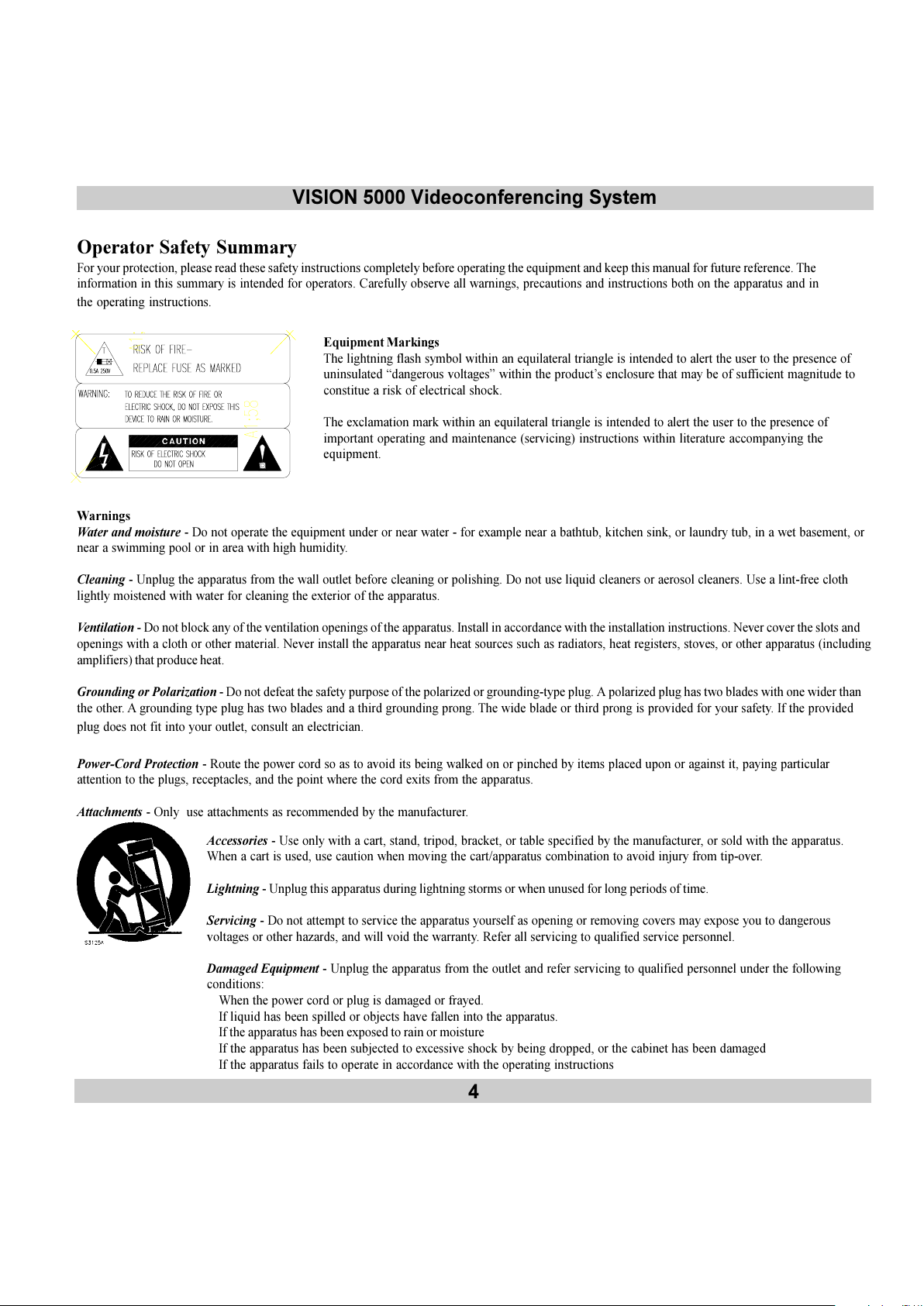
Equipment Markings
The lightning flash symbol within an equilateral triangle is intended to alert the user to the presence of
uninsulated dangerous voltages within the products enclosure that may be of sufficient magnitude to
constitue a risk of electrical shock.
The exclamation mark within an equilateral triangle is intended to alert the user to the presence of
important operating and maintenance (servicing) instructions within literature accompanying the
equipment.
Warnings
Water and moisture - Do not operate the equipment under or near water - for example near a bathtub, kitchen sink, or laundry tub, in a wet basement, or
near a swimming pool or in area with high humidity.
Cleaning - Unplug the apparatus from the wall outlet before cleaning or polishing. Do not use liquid cleaners or aerosol cleaners. Use a lint-free cloth
lightly moistened with water for cleaning the exterior of the apparatus.
Ventilation - Do not block any of the ventilation openings of the apparatus. Install in accordance with the installation instructions. Never cover the slots and
openings with a cloth or other material. Never install the apparatus near heat sources such as radiators, heat registers, stoves, or other apparatus (including
amplifiers) that produce heat.
Grounding or Polarization - Do not defeat the safety purpose of the polarized or grounding-type plug. A polarized plug has two blades with one wider than
the other. A grounding type plug has two blades and a third grounding prong. The wide blade or third prong is provided for your safety. If the provided
plug does not fit into your outlet, consult an electrician.
Power-Cord Protection - Route the power cord so as to avoid its being walked on or pinched by items placed upon or against it, paying particular
attention to the plugs, receptacles, and the point where the cord exits from the apparatus.
Attachments - Only use attachments as recommended by the manufacturer.
Accessories - Use only with a cart, stand, tripod, bracket, or table specified by the manufacturer, or sold with the apparatus.
When a cart is used, use caution when moving the cart/apparatus combination to avoid injury from tip-over.
Lightning - Unplug this apparatus during lightning storms or when unused for long periods of time.
Servicing - Do not attempt to service the apparatus yourself as opening or removing covers may expose you to dangerous
voltages or other hazards, and will void the warranty. Refer all servicing to qualified service personnel.
Damaged Equipment - Unplug the apparatus from the outlet and refer servicing to qualified personnel under the following
conditions:
When the power cord or plug is damaged or frayed.
If liquid has been spilled or objects have fallen into the apparatus.
If the apparatus has been exposed to rain or moisture
If the apparatus has been subjected to excessive shock by being dropped, or the cabinet has been damaged
If the apparatus fails to operate in accordance with the operating instructions
All manuals and user guides at all-guides.com
Page 5
VISION 5000 Videoconferencing System
5
Contents
Introduction ...................................................................................7
How to use this guide ................................................................................................... 7
Menu structure..............................................................................8
Vision 5000 videoconferencing system .......................................9
At a glance the Vision 5000 system ........................................................................9
Installation .................................................................................. 13
Precautions .................................................................................................................13
Unpacking................................................................................................................... 14
Connecting cables....................................................................................................... 15
Power on monitor ....................................................................................................... 16
Power on codec.......................................................................................................... 17
Configuration .............................................................................................................. 18
Environmental considerations ..................................................................................... 19
Getting started ........................................................................... 23
System start-up ........................................................................................................... 23
On-screen help ........................................................................................................... 23
Basics ......................................................................................................................... 24
Making and ending calls ............................................................................................. 25
General use................................................................................. 28
Adjusting volume ........................................................................................................ 28
View outgoing video ...................................................................................................28
Microphone on/off ...................................................................................................... 29
Moving the picture-in-picture (PIP) ...........................................................................29
Controlling the Main Camera ..................................................................................... 29
Camera Tracking ........................................................................................................ 30
Selecting video sources .............................................................................................. 31
Selecting audio sources .............................................................................................. 31
Presets ........................................................................................................................ 32
Sending/receiving graphics ......................................................................................... 33
Far end camera control (FECC)................................................................................. 35
All manuals and user guides at all-guides.com
Page 6
6
VISION 5000 Videoconferencing System
Advanced use.............................................................................. 36
General .......................................................................................................................36
Main menu .................................................................................................................. 37
Call quality .................................................................................................................. 38
Edit directory .............................................................................................................. 41
Utilities ........................................................................................................................44
MCU services ............................................................................................................50
Audio setup .................................................................................................................53
Video input .................................................................................................................. 59
Camera adjustments ...................................................................................................60
Video output ................................................................................................................62
Terminal settings ......................................................................................................... 63
Network configuration ................................................................................................ 63
Dataport configuration ................................................................................................ 72
Restore defaults.......................................................................................................... 74
TCP/IP Settings.......................................................................................................... 75
Ethernet Functionality .............................................................. 76
WWW-interface ......................................................................................................... 76
Peripheral Equipment ............................................................... 78
Interfaces ................................................................................................................... 79
Dual Monitor (optional) .............................................................................................. 80
Natural Audio module (optional)................................................................................. 81
AudioScience module (optional) ................................................................................. 81
Multiple controllable cameras (optional) ..................................................................... 82
Tracker (optional) ....................................................................................................... 82
Document camera ...................................................................................................... 83
Video Cassette Recorder (VCR) ............................................................................... 84
Telephone Add-On ..................................................................................................... 85
Extra cameras ............................................................................................................85
PC applications ........................................................................................................... 86
Additional microphones .............................................................................................. 87
Appendices .................................................................................. 88
Index ............................................................................................ 94
All manuals and user guides at all-guides.com
all-guides.com
Page 7
VISION 5000 Videoconferencing System
7
Introduction
This User Manual is provided to help you make the best use of your Vision 5000 system. The Vision 5000
offers superior quality audio and video in a fully-featured rollabout unit. Incorporating plug and play
technology, the system can be effortlessly moved within the office environment. The Vision 5000 is an ideal
choice for mid to large group applications and is available with single or dual monitors.
Features:
Compatibility with other videoconferencing systems conforming to the H.320 and T.120 standards.
Selection of up to 12B channel (768 kbps) call quality.
SoftMux - innovative internal software IMUX which increases reliability and eliminates the need for an
additional external multiplexer.
Downspeed - if channels are dropped during a videoconferencing session, Downspeeding automatically
maintains the connection without interrupting the call in progress.
W.A.V.E (Wide Angle View) Camera - delivers the widest angle of view in the industry.
Support for multiple W.A.V.E. Cameras.
Web-interface for management and diagnostics.
Software upgrades via LAN.
Natural Audio module - Frequency-compensated loudspeaker system optimised for voice response.
Provision for connecting auxiliary cameras, additional microphones, document camera, telephone add-on,
Personal Computer (PC), and Video Cassette Recorder (VCR).
On-screen real-time user feedback and help.
The Vision 5000 is available with different network configurations.
To find your configuration, see Power Up and System Info or boot-up text.
How to use this guide
to gain a basic understanding of how to control your system - see Getting startedand General use.
when you need to use basic features - see General use.
as a reference when you need more details about the system features - see Advanced use.
Hints and tips boxes
In this guide, weve included
helpful tips and notes. They
appear in grey boxes like
this one.
All manuals and user guides at all-guides.com
Page 8
8
VISION 5000 Videoconferencing System
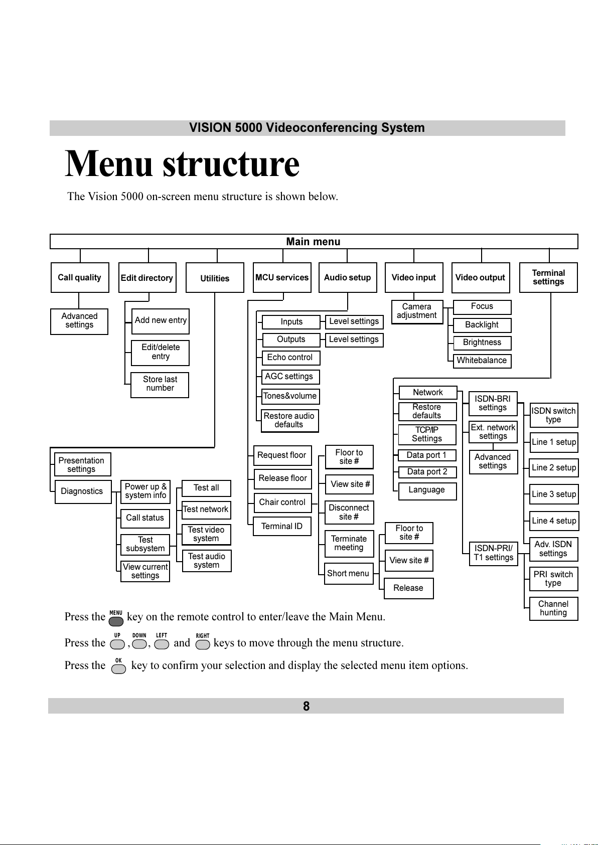
Menu structure
The Vision 5000 on-screen menu structure is shown below.
Press the
MENU
key on the remote control to enter/leave the Main Menu.
Press the
UP
,
DOWN
,
LEFT
and
RIGHT
keys to move through the menu structure.
Press the OK key to confirm your selection and display the selected menu item options.
Floor to
site #
View site #
Disconnect
site #
Terminate
meeting
Call quality Audio setup
Video input
Edit directory
Utilities
Video outputMCU services
Terminal
settings
Advanced
settings
Echo control
Tones&volume
Presentation
settings
Request floor
Release floor
Chair control
Terminal ID
Network
Restore
defaults
Data port 1
Language
ISDN switch
type
Line 1 setup
Line 2 setup
Line 3 setup
Adv. ISDN
settings
Power up &
system info
Call status
Test
subsystem
View current
settings
Test video
system
Test audio
system
Test network
Camera
adjustment
Short menu
Floor to
site #
View site #
Release
Test all
Main menu
Diagnostics
ISDN-BRI
settings
Ext. network
settings
Line 4 setup
ISDN-PRI/
T1 settings
Advanced
settings
Add new entry
Edit/delete
entry
Store last
number
Inputs
Outputs
AGC settings
Restore audio
defaults
Level settings
Level settings
Data port 2
Focus
Backlight
Brightness
Whitebalance
TCP/IP
Settings
PRI switch
type
Channel
hunting
All manuals and user guides at all-guides.com
Page 9

VISION 5000 Videoconferencing System
9
Vision 5000
videoconferencing system
At a glance the Vision 5000 system
All manuals and user guides at all-guides.com
Page 10
10
VISION 5000 Videoconferencing System
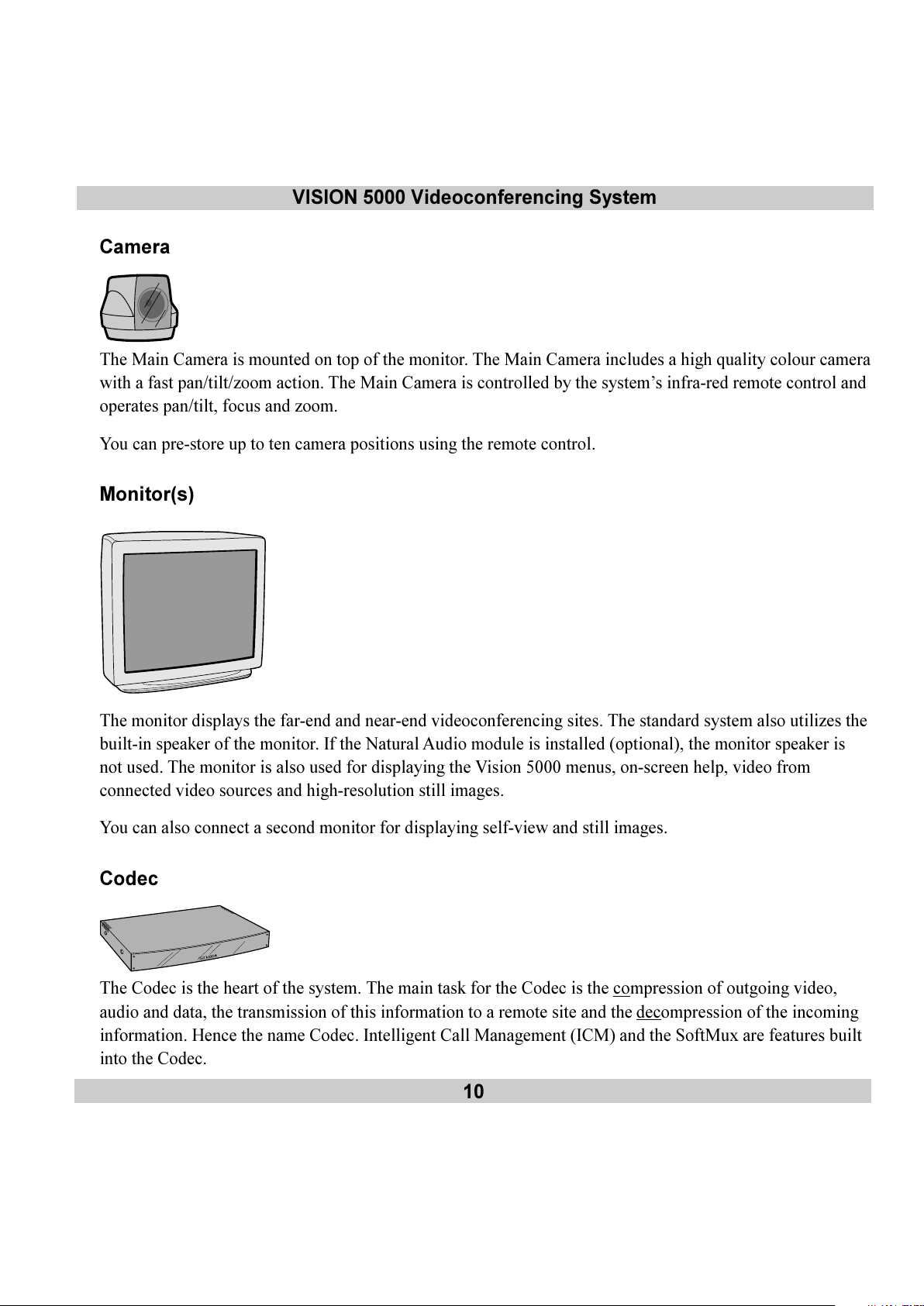
Camera
The Main Camera is mounted on top of the monitor. The Main Camera includes a high quality colour camera
with a fast pan/tilt/zoom action. The Main Camera is controlled by the systems infra-red remote control and
operates pan/tilt, focus and zoom.
You can pre-store up to ten camera positions using the remote control.
Monitor(s)
The monitor displays the far-end and near-end videoconferencing sites. The standard system also utilizes the
built-in speaker of the monitor. If the Natural Audio module is installed (optional), the monitor speaker is
not used. The monitor is also used for displaying the Vision 5000 menus, on-screen help, video from
connected video sources and high-resolution still images.
You can also connect a second monitor for displaying self-view and still images.
Codec
The Codec is the heart of the system. The main task for the Codec is the compression of outgoing video,
audio and data, the transmission of this information to a remote site and the
decompression of the incoming
information. Hence the name Codec. Intelligent Call Management (ICM) and the SoftMux are features built
into the Codec.
All manuals and user guides at all-guides.com
Page 11
VISION 5000 Videoconferencing System
11
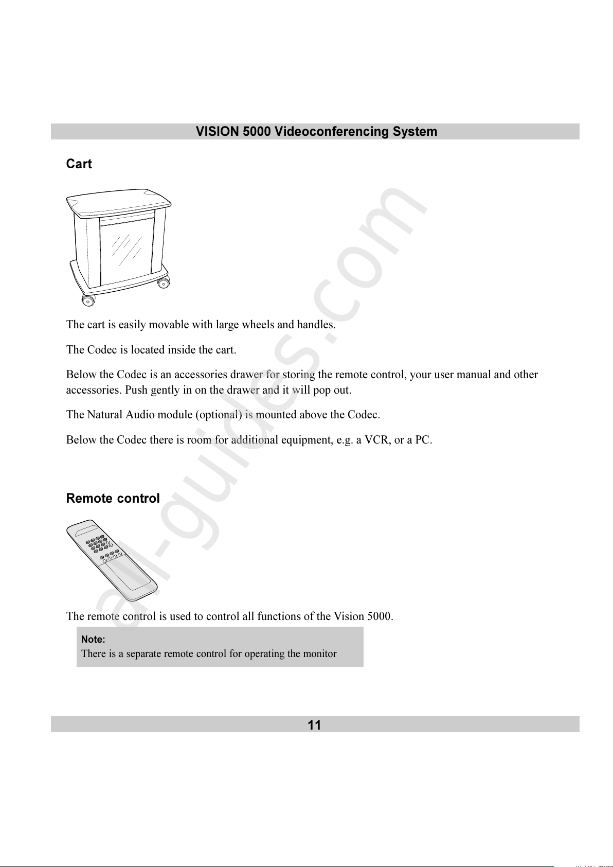
Cart
The cart is easily movable with large wheels and handles.
The Codec is located inside the cart.
Below the Codec is an accessories drawer for storing the remote control, your user manual and other
accessories. Push gently in on the drawer and it will pop out.
The Natural Audio module (optional) is mounted above the Codec.
Below the Codec there is room for additional equipment, e.g. a VCR, or a PC.
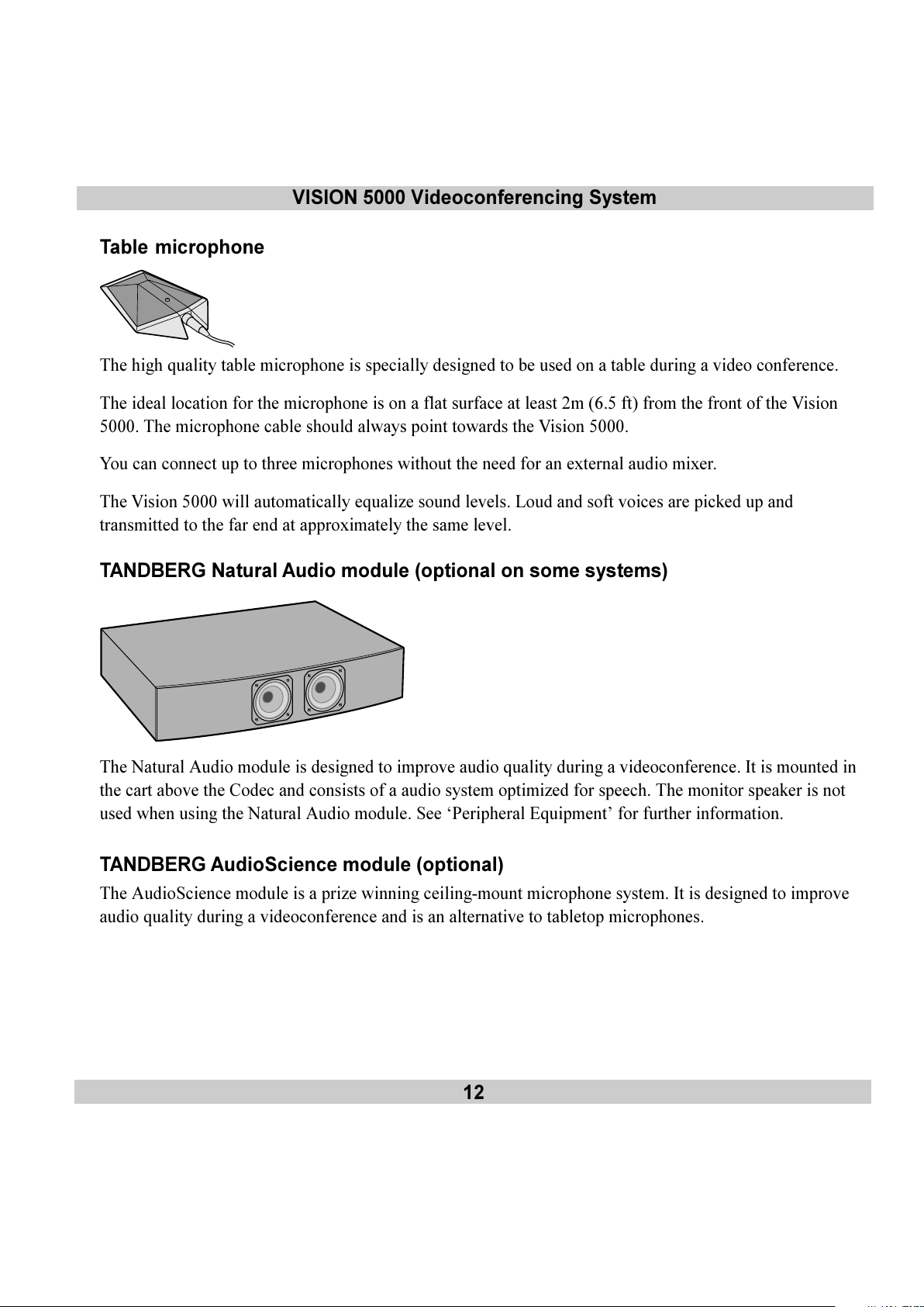
Remote control
The remote control is used to control all functions of the Vision 5000.
Note:
There is a separate remote control for operating the monitor
All manuals and user guides at all-guides.com
all-guides.com
Page 12
12
VISION 5000 Videoconferencing System
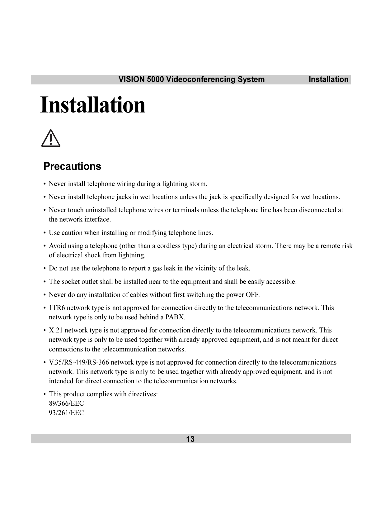
Table microphone
The high quality table microphone is specially designed to be used on a table during a video conference.
The ideal location for the microphone is on a flat surface at least 2m (6.5 ft) from the front of the Vision
5000. The microphone cable should always point towards the Vision 5000.
You can connect up to three microphones without the need for an external audio mixer.
The Vision 5000 will automatically equalize sound levels. Loud and soft voices are picked up and
transmitted to the far end at approximately the same level.
TANDBERG Natural Audio module (optional on some systems)
The Natural Audio module is designed to improve audio quality during a videoconference. It is mounted in
the cart above the Codec and consists of a audio system optimized for speech. The monitor speaker is not
used when using the Natural Audio module. See Peripheral Equipment for further information.
TANDBERG AudioScience module (optional)
The AudioScience module is a prize winning ceiling-mount microphone system. It is designed to improve
audio quality during a videoconference and is an alternative to tabletop microphones.
All manuals and user guides at all-guides.com
Page 13
VISION 5000 Videoconferencing System
13
Installation
Precautions
Never install telephone wiring during a lightning storm.
Never install telephone jacks in wet locations unless the jack is specifically designed for wet locations.
Never touch uninstalled telephone wires or terminals unless the telephone line has been disconnected at
the network interface.
Use caution when installing or modifying telephone lines.
Avoid using a telephone (other than a cordless type) during an electrical storm. There may be a remote risk
of electrical shock from lightning.
Do not use the telephone to report a gas leak in the vicinity of the leak.
The socket outlet shall be installed near to the equipment and shall be easily accessible.
Never do any installation of cables without first switching the power OFF.
1TR6 network type is not approved for connection directly to the telecommunications network. This
network type is only to be used behind a PABX.
X.21 network type is not approved for connection directly to the telecommunications network. This
network type is only to be used together with already approved equipment, and is not meant for direct
connections to the telecommunication networks.
V.35/RS-449/RS-366 network type is not approved for connection directly to the telecommunications
network. This network type is only to be used together with already approved equipment, and is not
intended for direct connection to the telecommunication networks.
This product complies with directives:
89/366/EEC
93/261/EEC
Installation
All manuals and user guides at all-guides.com
Page 14

14
VISION 5000 Videoconferencing SystemInstallation
Unpacking
To avoid damage to the unit during transportation the Vision 5000 is delivered as separate components. We
recommended that you store all packaging material in case the need should arise to transport the system to
another location.
Note
Please follow the instructions carefully.
The Vision 5000 consists of the following items:
Cart
High quality monitor
Option: Dual Monitor. Consists of an extra cart and an additional high quality monitor
Inside the cart you should find the accessories box which will contain the following:
Camera
Table Microphone
Remote Control
Batteries
User Manuals
Monitor securing kit and other documentation
Please retain the accessories box in case of future
transportation requirements.
Place the monitor on top of the cart and ensure it is stable. You
may fasten the monitor to the cart using the securing kit. Take
the camera and remove the plastic backing from the double
sided tape-pads on the base of the unit. Place the camera
centrally, on top of the monitor close to the front (see picture
on left).
Important
The camera should be aligned
with the front edge of the
monitor to ensure the IR-sensor
in the camera can pick up
signals from the remote control.
All manuals and user guides at all-guides.com
Page 15
VISION 5000 Videoconferencing System
15
Installation
Connecting cables
All cables needed in standard configuration are connected to the Codec. These Codec inputs are marked
green. Connect:
Vision 5000 power cable and monitor power cable to an electrical distribution socket.
Europe: Scart connector to one of the Scart connectors on the monitor, (for a 29 monitor, use Ext-1).
USA: Connect the cable terminating in two RCA connectors and one S-video connector to the monitor. The
two RCA connectors are for the left and right audio channels (not if Natural Audio module is mounted). The
S-video connector is for video. The audio signal from the Vision 5000 is a monaural signal and therefore is
fed into both audio-in sockets on the monitor.
Microphone to the microphone cable.
Connect the camera and the camera cable. The camera cable terminates in a 15 pin D-SUB connector.
ISDN cables - using BRI interface
Take the four ends of the ISDN cables and verify that they are labelled ISDN 1, 2, 3 and 4.
Note
Some software versions of Vision 5000 do not support 4 ISDN lines.
Connect ISDN cable No. 1 to the first ISDN socket (S/T-interface) provided by the service provider. This
will be your main number. Connect ISDN cable No. 2 to the second ISDN socket, ISDN cable No. 3 to
the third ISDN socket and ISDN cable No. 4 to the fourth socket (if used).
USA: The Vision 5000 does not have a built in network terminator. If your wall socket provides you with an
ISDN U-interface, you will need an NT1 between your Vision 5000 and your ISDN line, see Appendix 1.
Note
Write down the numbers associated with each of the ISDN lines. You will need them later to configure the system.
Connecting to the Switched 56 network
When connecting to the Switched 56 network you may use one of the BRI interfaces or the V.35 interface
on the Vision 5000. Please refer to Appendix 2 for further information.
ISDN cable - using the PRI/T1 interface
If you are using the PRI/T1 interface, the PRI/T1 cable should be connected to a CSU (Channel Service Unit).
You will need a CSU between your Vision 5000 and the line from your network provider, see Appendix 3.
All manuals and user guides at all-guides.com
Page 16
16
VISION 5000 Videoconferencing SystemInstallation
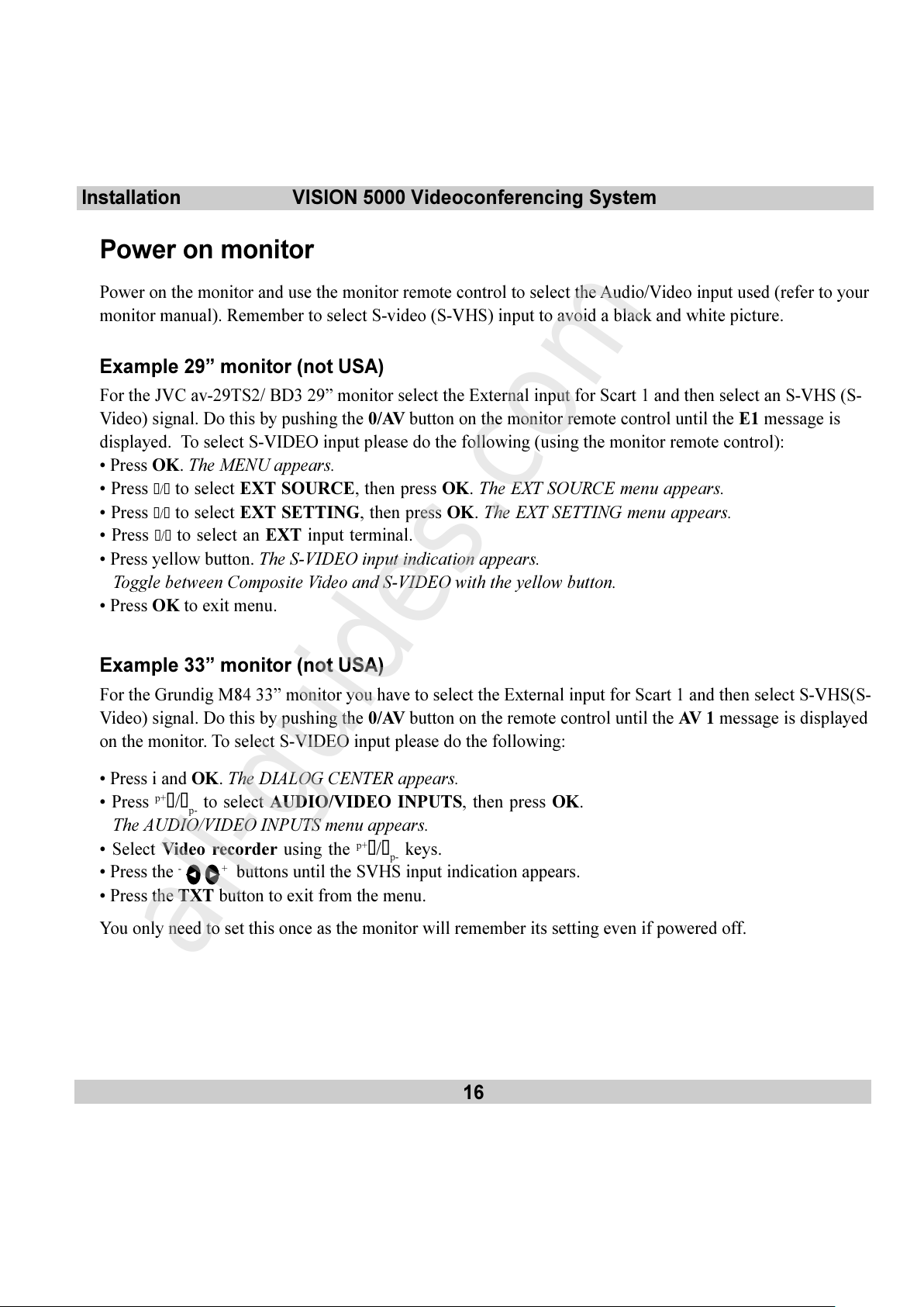
Power on monitor
Power on the monitor and use the monitor remote control to select the Audio/Video input used (refer to your
monitor manual). Remember to select S-video (S-VHS) input to avoid a black and white picture.
Example 29 monitor (not USA)
For the JVC av-29TS2/ BD3 29 monitor select the External input for Scart 1 and then select an S-VHS (S-
Video) signal. Do this by pushing the 0/AV button on the monitor remote control until the E1 message is
displayed. To select S-VIDEO input please do the following (using the monitor remote control):
Press OK. The MENU appears.
Press
s/t to select EXT SOURCE, then press OK. The EXT SOURCE menu appears.
Press
s/t to select EXT SETTING, then press OK. The EXT SETTING menu appears.
Press
s/t to select an EXT input terminal.
Press yellow button. The S-VIDEO input indication appears.
Toggle between Composite Video and S-VIDEO with the yellow button.
Press OK to exit menu.
Example 33 monitor (not USA)
For the Grundig M84 33 monitor you have to select the External input for Scart 1 and then select S-VHS(S-
Video) signal. Do this by pushing the 0/AV button on the remote control until the AV 1 message is displayed
on the monitor. To select S-VIDEO input please do the following:
Press i and OK. The DIALOG CENTER appears.
Press
p+
s/tp- to select AUDIO/VIDEO INPUTS, then press OK.
The AUDIO/VIDEO INPUTS menu appears.
Select Video recorder using the
p+
s/tp- keys.
Press the
-
+ buttons until the SVHS input indication appears.
Press the TXT button to exit from the menu.
You only need to set this once as the monitor will remember its setting even if powered off.
All manuals and user guides at all-guides.com
all-guides.com
Page 17
VISION 5000 Videoconferencing System
17
Installation
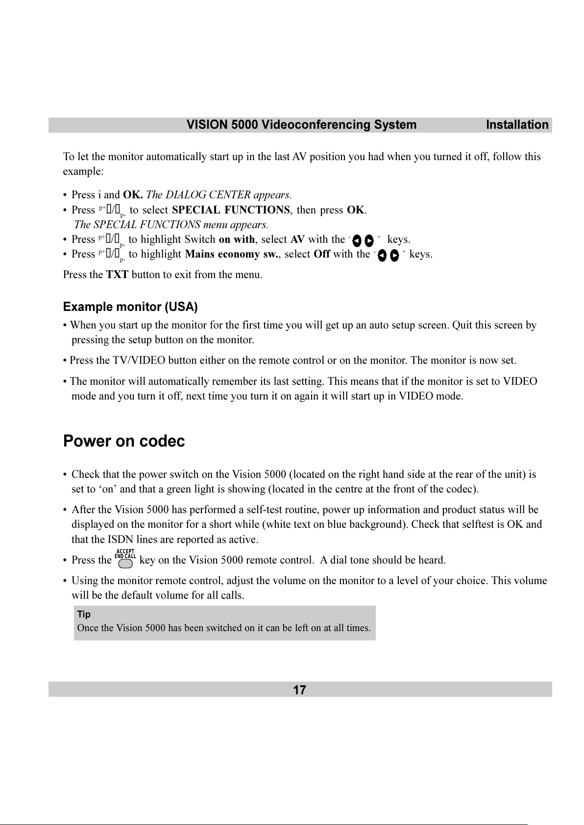
To let the monitor automatically start up in the last AV position you had when you turned it off, follow this
example:
Press i and OK. The DIALOG CENTER appears.
Press
p+
s/tp- to select SPECIAL FUNCTIONS, then press OK.
The SPECIAL FUNCTIONS menu appears.
Press
p+
s/tp- to highlight Switch on with, select AV with the - + keys.
Press
p+
s/tp- to highlight Mains economy sw., select Off with the - + keys.
Press the TXT button to exit from the menu.
Example monitor (USA)
When you start up the monitor for the first time you will get up an auto setup screen. Quit this screen by
pressing the setup button on the monitor.
Press the TV/VIDEO button either on the remote control or on the monitor. The monitor is now set.
The monitor will automatically remember its last setting. This means that if the monitor is set to VIDEO
mode and you turn it off, next time you turn it on again it will start up in VIDEO mode.
Power on codec
Check that the power switch on the Vision 5000 (located on the right hand side at the rear of the unit) is
set to on and that a green light is showing (located in the centre at the front of the codec).
After the Vision 5000 has performed a self-test routine, power up information and product status will be
displayed on the monitor for a short while (white text on blue background). Check that selftest is OK and
that the ISDN lines are reported as active.
Press the
ACCEPT
END CALL
key on the Vision 5000 remote control. A dial tone should be heard.
Using the monitor remote control, adjust the volume on the monitor to a level of your choice. This volume
will be the default volume for all calls.
Tip
Once the Vision 5000 has been switched on it can be left on at all times.
All manuals and user guides at all-guides.com
Page 18
18
VISION 5000 Videoconferencing SystemInstallation
Configuration
For each installation of the Vision 5000 it is necessary to configure the unit. All configuration parameters are
available via the Terminal Settings menu through the on-screen menu system. If you are using an external
IMUX or special networks, the external equipment may also need to be configured.
Press
MENU
on the remote control. Select the menu Terminal Settings, then Network.
ISDN-BRI configuration
When using the internal SoftMux on ISDN-BRI, select Current Network: ISDN-BRI, enter ISDN-BRI
Settings, select Switch Type and Line1-4 Setup. For details, follow the instructions in chapter Terminal
Settings, ISDN-BRI Settings in this guide.
For further information refer to the examples in:
Appendix 1: Connecting Vision 5000 to ISDN using NT1 network adapters
Appendix 2: Connecting Vision 5000 to the Switched 56 network
ISDN-PRI/T1 configuration
When using the internal SoftMux on ISDN-PRI/T1, select Current Network: ISDN-PRI/T1, enter ISDN-
PRI/T1 Settings and specify needed parameters. For details, follow the instructions in chapter Terminal
Settings,ISDN-PRI/T1 Settings in this guide.
External Network configuration
When using external network equipment such as an external IMUX or terminal adapters for special
networks, select Current Network: External and set your network specific parameters via the External
Network Settings option. For details, follow the instructions in chapter Terminal Settings,External
Network Settings in this guide.
Language and Dual Monitor configuration
To select a different language, select Terminal Settings, Language.
If you are using two monitors, Dual monitor should be selected On in the Video Output menu.
The Vision 5000 is now configured and ready to make a call.
All manuals and user guides at all-guides.com
Page 19
VISION 5000 Videoconferencing System
19
Installation
Environmental considerations
This section explains how to carry out basic adjustments and simple tests to ensure that you send and receive
the best possible image and audio quality when using your Vision 5000.
Iris control and lighting
By default the Vision 5000 camera will use an automatic iris to compensate for changes in lighting. In
addition to this feature you may further assist the Vision 5000 to maintain the best possible image quality by
paying special attention to environmental lighting and background colours as described below. Remember
the Vision 5000 will send live images of yourself and your immediate surroundings.
Avoid direct sunlight on the subject matter i.e. yourself, the background or onto the camera lens as this
will create harsh contrasts.
If light levels are too low you may need to consider using artificial lighting. As above avoid direct
illumination of the subject matter and camera lens.
When using artificial lighting, daylight type lamps will produce the most effective results. Avoid
coloured lighting.
Indirect light from shaded sources or reflected light from pale walls, often produces excellent results.
Avoid harsh side lighting or strong light from above, for example: strong sunlight from a window or
skylight, as this may put part or all of the subject matter in shadow or cause silhouetting.
If you still have problems with the iris and lighting, manual adjustment of the camera parameters might
help - see Camera adjustments in Video Input menu.
Dim scenes can also be improved by manually adjusting the camera brightness setting.
Background
The appearance of the picture background is very important but easily overlooked. It is important to
remember that the camera also shows whats behind you when in a videoconference. To ensure a suitable
background we recommend you consider the following:
Use a neutrally coloured background with a medium contrast and a soft texture, e.g. a plain curtain with
no heavy patterns or strong colours that may adversely tint the whole scene.
All manuals and user guides at all-guides.com
Page 20
20
VISION 5000 Videoconferencing SystemInstallation
Avoid moving backgrounds, for example: curtains in a draught, moving objects, or people walking behind
you, as this may both reduce image quality and distract the attention of the calling party.
Do not place the camera facing a doorway.
Brightness control
For adjusting brightness, colours or other settings of the TV monitor, you must use the TV monitors own
remote control. Adjust the TV monitor to suit the conditions of the conference room.
The TV monitor has an on-screen menu and is very easy to use. For more information on configuring the TV
monitor refer to the user manual for that unit.
Loudspeaker volume
The audio system will use the loudspeakers built into the TV monitor or the Natural Audio module (if
installed). The volume of the audio system is controlled by the Volume Control keys on the Vision 5000 hand-
held remote control.
The default volume level can be set by adjusting the volume on the TV monitor using the TV monitors own
remote control.
All manuals and user guides at all-guides.com
Page 21
VISION 5000 Videoconferencing System
21
Installation
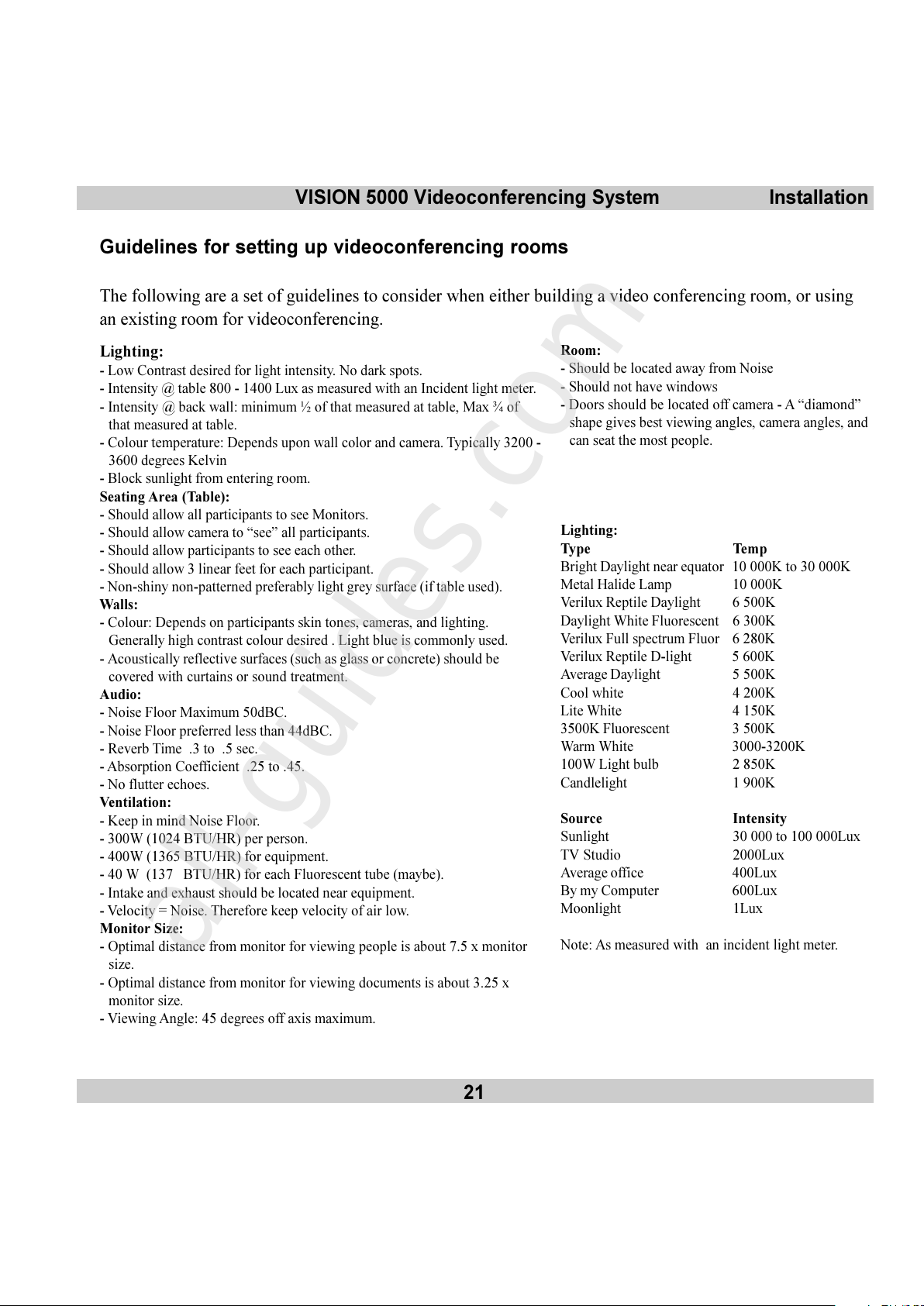
Guidelines for setting up videoconferencing rooms
The following are a set of guidelines to consider when either building a video conferencing room, or using
an existing room for videoconferencing.
Room:
- Should be located away from Noise
- Should not have windows
- Doors should be located off camera - A diamond
shape gives best viewing angles, camera angles, and
can seat the most people.
Lighting:
Type Temp
Bright Daylight near equator 10 000K to 30 000K
Metal Halide Lamp 10 000K
Verilux Reptile Daylight 6 500K
Daylight White Fluorescent 6 300K
Verilux Full spectrum Fluor 6 280K
Verilux Reptile D-light 5 600K
Average Daylight 5 500K
Cool white 4 200K
Lite White 4 150K
3500K Fluorescent 3 500K
Warm White 3000-3200K
100W Light bulb 2 850K
Candlelight 1 900K
Source Intensity
Sunlight 30 000 to 100 000Lux
TV Studio 2000Lux
Average office 400Lux
By my Computer 600Lux
Moonlight 1Lux
Note: As measured with an incident light meter.
Lighting:
- Low Contrast desired for light intensity. No dark spots.
- Intensity @ table 800 - 1400 Lux as measured with an Incident light meter.
- Intensity @ back wall: minimum ½ of that measured at table, Max ¾ of
that measured at table.
- Colour temperature: Depends upon wall color and camera. Typically 3200 -
3600 degrees Kelvin
- Block sunlight from entering room.
Seating Area (Table):
- Should allow all participants to see Monitors.
- Should allow camera to see all participants.
- Should allow participants to see each other.
- Should allow 3 linear feet for each participant.
- Non-shiny non-patterned preferably light grey surface (if table used).
Walls:
- Colour: Depends on participants skin tones, cameras, and lighting.
Generally high contrast colour desired . Light blue is commonly used.
- Acoustically reflective surfaces (such as glass or concrete) should be
covered with curtains or sound treatment.
Audio:
- Noise Floor Maximum 50dBC.
- Noise Floor preferred less than 44dBC.
- Reverb Time .3 to .5 sec.
- Absorption Coefficient .25 to .45.
- No flutter echoes.
Ventilation:
- Keep in mind Noise Floor.
- 300W (1024 BTU/HR) per person.
- 400W (1365 BTU/HR) for equipment.
- 40 W (137 BTU/HR) for each Fluorescent tube (maybe).
- Intake and exhaust should be located near equipment.
- Velocity = Noise. Therefore keep velocity of air low.
Monitor Size:
- Optimal distance from monitor for viewing people is about 7.5 x monitor
size.
- Optimal distance from monitor for viewing documents is about 3.25 x
monitor size.
- Viewing Angle: 45 degrees off axis maximum.
All manuals and user guides at all-guides.com
all-guides.com
Page 22
22
VISION 5000 Videoconferencing SystemInstallation
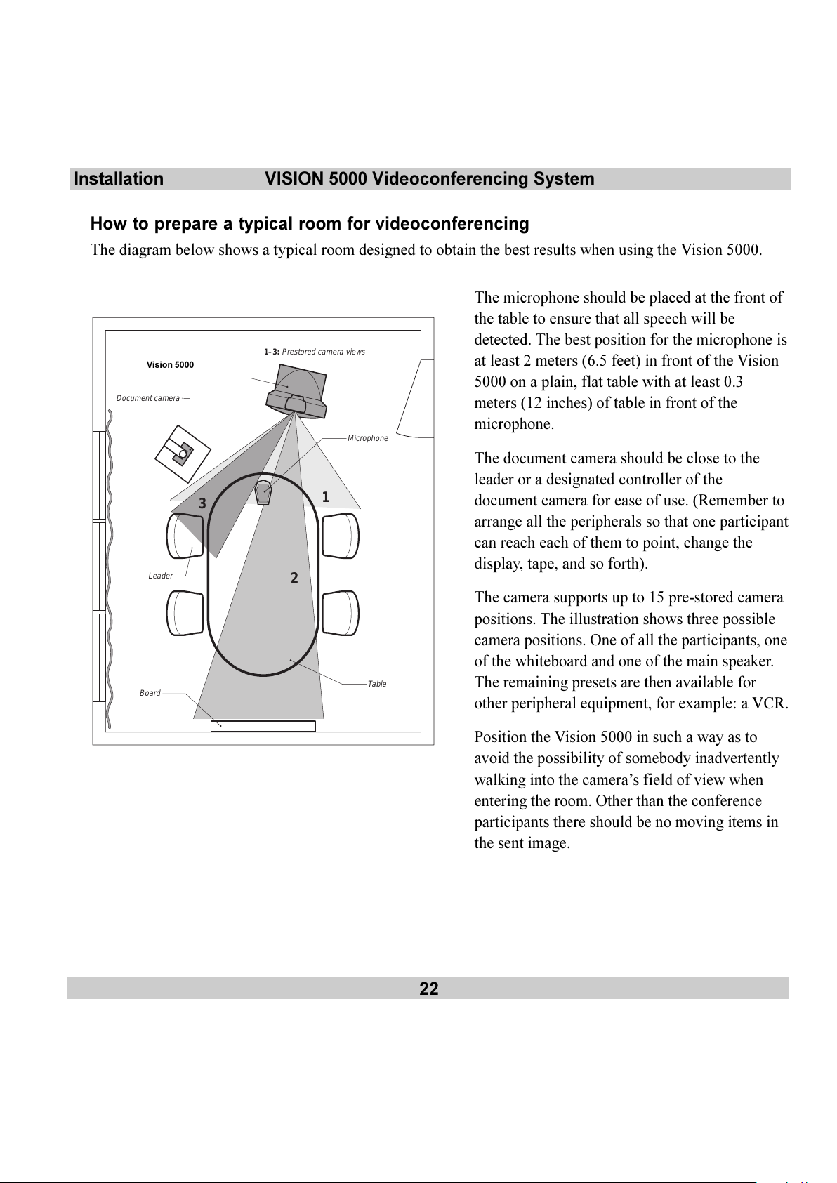
How to prepare a typical room for videoconferencing
The diagram below shows a typical room designed to obtain the best results when using the Vision 5000.
1
1–3:
Prestored camera views
2
3
Grand Vison
Leader
Board
Microphone
Table
Document camera
The microphone should be placed at the front of
the table to ensure that all speech will be
detected. The best position for the microphone is
at least 2 meters (6.5 feet) in front of the Vision
5000 on a plain, flat table with at least 0.3
meters (12 inches) of table in front of the
microphone.
The document camera should be close to the
leader or a designated controller of the
document camera for ease of use. (Remember to
arrange all the peripherals so that one participant
can reach each of them to point, change the
display, tape, and so forth).
The camera supports up to 15 pre-stored camera
positions. The illustration shows three possible
camera positions. One of all the participants, one
of the whiteboard and one of the main speaker.
The remaining presets are then available for
other peripheral equipment, for example: a VCR.
Position the Vision 5000 in such a way as to
avoid the possibility of somebody inadvertently
walking into the cameras field of view when
entering the room. Other than the conference
participants there should be no moving items in
the sent image.
Vision 5000
All manuals and user guides at all-guides.com
Page 23
VISION 5000 Videoconferencing System
23
Getting started
On-screen help
Press the
HELP
key to get help.
The help system has two formats:
1. A separate Help Menu.
2. Context sensitive help, i.e. HELP relative to wherever you are in the menu system.
Getting started
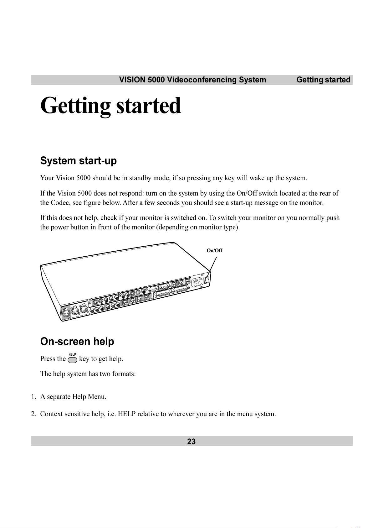
System start-up
Your Vision 5000 should be in standby mode, if so pressing any key will wake up the system.
If the Vision 5000 does not respond: turn on the system by using the On/Off switch located at the rear of
the Codec, see figure below. After a few seconds you should see a start-up message on the monitor.
If this does not help, check if your monitor is switched on. To switch your monitor on you normally push
the power button in front of the monitor (depending on monitor type).
On/Off
All manuals and user guides at all-guides.com
Page 24
24
VISION 5000 Videoconferencing SystemGetting started
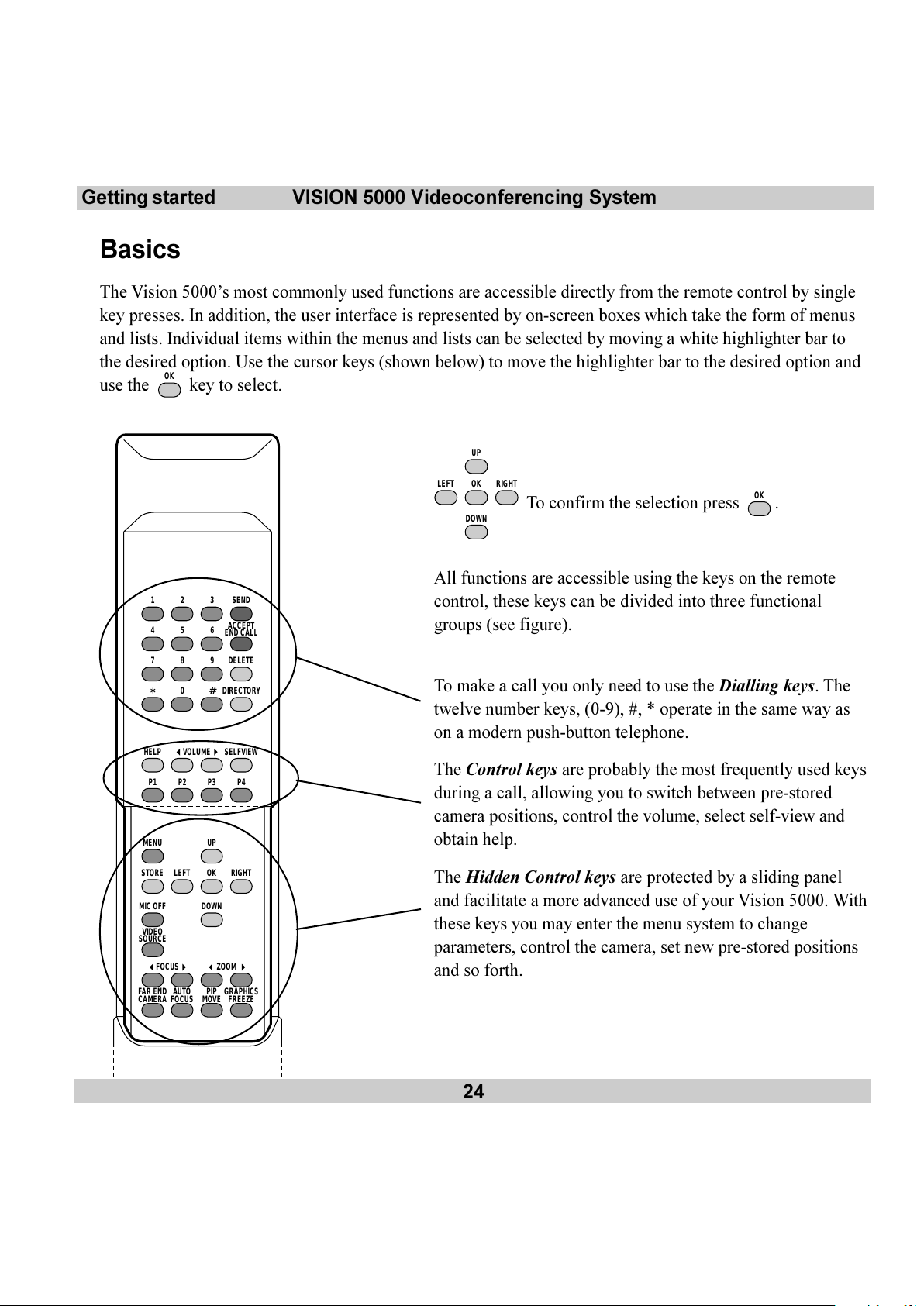
Basics
The Vision 5000s most commonly used functions are accessible directly from the remote control by single
key presses. In addition, the user interface is represented by on-screen boxes which take the form of menus
and lists. Individual items within the menus and lists can be selected by moving a white highlighter bar to
the desired option. Use the cursor keys (shown below) to move the highlighter bar to the desired option and
use the
OK
key to select.
UP
RIGHTOKLEFT
DOWN
To confirm the selection press OK.
All functions are accessible using the keys on the remote
control, these keys can be divided into three functional
groups (see figure).
To make a call you only need to use the Dialling keys. The
twelve number keys, (0-9), #, * operate in the same way as
on a modern push-button telephone.
The Control keys are probably the most frequently used keys
during a call, allowing you to switch between pre-stored
camera positions, control the volume, select self-view and
obtain help.
The Hidden Control keys are protected by a sliding panel
and facilitate a more advanced use of your Vision 5000. With
these keys you may enter the menu system to change
parameters, control the camera, set new pre-stored positions
and so forth.
SEND321
ACCEPT
END CALL
654
DELETE987
DIRECTORY
#
0
*
HELP
MENU UP
VOLUME
FOCUS ZOOM
MIC OFF
VIDEO
SOURCE
FAR END
CAMERA
AUTO
FOCUS
PIP
MOVE
GRAPHICS
FREEZE
SELFVIEW
RIGHTOKLEFT
DOWN
STORE
P4P3P2P1
All manuals and user guides at all-guides.com
Page 25
VISION 5000 Videoconferencing System
25
Getting started
Making and ending calls
Making a call
The Vision 5000 has its own internal software controlled inverse multiplexer, SoftMux and uses Intelligent
Call Management (ICM). This enables you to dial to other videoconferencing equipment, phones and
mobile phones without needing to use a prefix. ICM provides you with on-screen, real-time feedback on the
progress of a call. You will, when calling to videoconferencing equipment, obtain a connection on as many
channels as possible.
External Networks
ICM is not available when using an external IMUX or when connecting via special networks.
Ending a call
Switching off the monitor(s) will not disconnect a call. To disconnect a call you should press the
ACCEPT
END CALL
key.
Video call
To make a video call, enter the number of the unit you wish to call using the Dialling keys and press
SEND
.
Example: 12345678 +
SEND
, 12345678 = Number
The system will, by default, try to connect using 6 channels and BONDING. If the requested number of
channels cannot be established, the system will establish a connection on as many channels as possible
(some limitations depending on remote system).
The SoftMux supports high reliability and includes the unique Downspeed feature. If channels are dropped
during a meeting, Downspeeding automatically maintains the connection without interrupting the call in
progress.
If you are calling to a unit that does not support more than 2 channels, the Vision 5000 will connect on 2
channels. When dialling to an analogue telephone, you will also connect without using a prefix. Due to ICM
you should never need to use any special prefix.
To force a special number of channels, see Special Call Prefixes.
The default number of channels may be changed , see Advanced ISDN settings in Advanced use.
All manuals and user guides at all-guides.com
Page 26
26
VISION 5000 Videoconferencing SystemGetting started
Dialling two numbers
Sometimes (especially calling to and within the USA) it is necessary to dial both ISDN numbers when
making a video call using 2x64 kbps or 2x56 kbps. Type in the first number followed by ** and edit the
automatically inserted second number by using the
DELETE
key and the number keys.
Example: 12345678 ** 12345679 +
SEND
Restricted call
A restricted call is a call to a 56 kbit network. By default the system will dial an unrestricted call (a call to a
64 kbit network). To force a restricted call, add a # at the end of the number being dialled.
Example: 12345678# +
SEND
Telephone call (SoftMux only)
To force a telephone call, press ** and then enter the number.
Example: **12345678 +
SEND
Special call prefixes
Default call type is #6* which means 6B BONDING. If you want to force another call type, you can use
one of the prefixes below. If you want your system to always dial another call type, see Default Call Type
in Advanced ISDN Settings.
Prefix Call Type
#12* 12B call (BONDING), 768 kbps (PRI and Ext.network only)
#8* 8B call (BONDING), 512 kbps
#6* 6B call (BONDING), 384 kbps
#5* 5B call (BONDING)
#4* 4B call (BONDING), 256 kbps
#3* 3B call (BONDING)
#2* 2B call (H.221), 128 kbps
#1* 1B call (H.221)
#92* 2B call (BONDING)
#91* 1B call (BONDING)
#81* 1xH0 channel call (PRI only)
** Telephone Call
Example: If you want to dial a 4-channel call, you can dial #4* 12345678 +
SEND
All manuals and user guides at all-guides.com
all-guides.com
Page 27
VISION 5000 Videoconferencing System
27
Getting started
Accept/end call
To answer a call, press the
SEND
or the
ACCEPT
END CALL
key. Manual answer of a call is needed if the autoanswer facility
is switched off. See Utilities in Advanced use.
To end a call, press the
ACCEPT
END CALL
key.
Correcting keying mistakes
To delete the last digit (or character) entered, press the
DELETE
key.
Last number redial/using the call directory
To get access to your list of pre-stored numbers (up to 99 entries) and the last number dialled, press the
DIRECTORY
key.
To select a number from the list, type the two-digit entry number or use UP and
DOWN
to move up/down, or
press
LEFT
and
RIGHT
to move one page up/down.
To dial the selected number press
SEND
.
Example: You wish to dial the number stored at entry number 03.
Press
DIRECTORY
+ 03 and
SEND
.
If you want to make changes to the number before dialling, press
OK
instead of
SEND
.
To program numbers and edit your directory list, see Edit Directory in Advanced use.
All manuals and user guides at all-guides.com
Page 28
28
VISION 5000 Videoconferencing SystemGeneral use
Press the
SELFVIEW
key to see your own picture (the outgoing video during a call).
If you have a single monitor system, the first button press provides you with your own picture (selfview) in
Picture-In-Picture. One more key press will provide you with your selfview in full screen size. The next press
will remove your selfview from the monitor.
Press the
PIP
MOVE
key to move the Picture-in-Picture to different corners of the screen.
Automatic selfview
To help you see your selfview when adjusting camera positions, your selfview will always appear in PIP when
you move your camera (if Auto-PIP is off, see Video Output in Advanced use)
If you have a dual monitor system, pressing the
SELFVIEW
key will toggle between your selfview and the last sent or
received still image on the dual monitor.
General use
Adjusting volume
Press the
VOLUME
keys to adjust the volume level. An on-screen indicator will show the current level.
Tip
It is important that you use the Volume control keys and not the monitor remote control. For best
performance set the volume level on the monitor initially using the dial-tone as a reference level and from
then on use only these volume keys. Too high a volume setting may result in echo being experienced by the
remote side of a video conference.
View outgoing video
All manuals and user guides at all-guides.com
Page 29
VISION 5000 Videoconferencing System
29
General use
Microphone on/off
To switch your microphone on/off during a call, press the
MIC OFF
key. An on screen indicator will appear when
the microphone is off.
Pressing
MIC OFF
will mute audio inputs Mic1-3 and Audio4. It will not mute audio input from AUX and VCR
(Audio input 5&6).
Moving the picture-in-picture (PIP)
Press the
PIP
MOVE
key to move the Picture-in-Picture to different corners of the screen.
Controlling the Main Camera
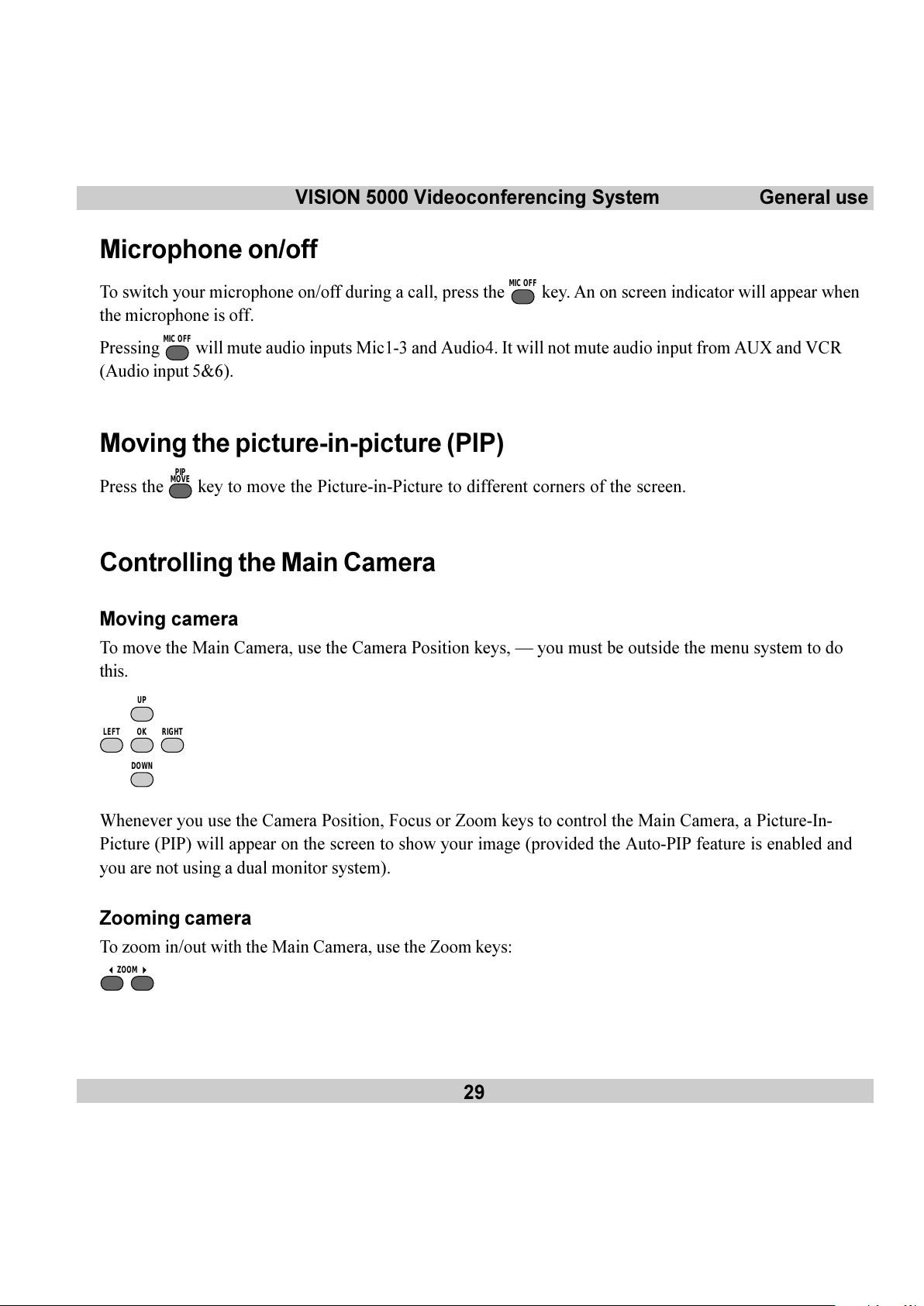
Moving camera
To move the Main Camera, use the Camera Position keys, you must be outside the menu system to do
this.
UP
RIGHTOKLEFT
DOWN
Whenever you use the Camera Position, Focus or Zoom keys to control the Main Camera, a Picture-In-
Picture (PIP) will appear on the screen to show your image (provided the Auto-PIP feature is enabled and
you are not using a dual monitor system).
Zooming camera
To zoom in/out with the Main Camera, use the Zoom keys:
ZOOM
All manuals and user guides at all-guides.com
Page 30

30
VISION 5000 Videoconferencing SystemGeneral use
Focusing camera
To manually focus the Main Camera, use the Focus keys:
FOCUS
The Main Camera is set for autofocus by default. An on screen indicator will appear whenever autofocus is
On.
If the Main Camera is moved (pan/tilt/zoom), autofocus will be switched On automatically for 5 seconds.
Camera Tracking
Before using camera tracking, presets P7 (Mic1), P8 (Mic2) and/or P9 (Mic3) must be stored using Video
Input #1 as the video source.
Example:
The camera position stored at P7 must be related to Mic1, therefore all participants which are located
closest to Mic1 should be included in the P7 camera position etc.
When camera tracking is activated and a person close to Mic1 speaks, P7 will be automatically selected.
If a person close to Mic1 has a conversation with a person close to Mic2, the camera will adjust to a
camera position which includes both persons.
Start camera tracking by selecting # in the Video Source menu (see the Selecting video sources section
for starting/stopping camera tracking).
When activating another video source (e.g. document camera), camera tracking will temporarily be disabled
until you select MainCam or a MainCam preset.
Pressing
MIC OFF
will temporarily disable camera tracking.
A Voice Detector makes the system more tolerent against noise and the camera will normally not be moved
by noise like paper shuffling etc.
The camera tracking speeds may be altered in the Video Input menu. See Advanced use for further
details.
All manuals and user guides at all-guides.com
Page 31

VISION 5000 Videoconferencing System
31
General use
Note
The Start Camera Tracking entry will be
greyed out if not using the standard Main
Camera.
Selecting video sources
======== Local Video Source =======
1 - MainCam
2 - Video2
3 - Video3
4 - Video4
5 - Video5
0 - View still image
# - Start Camera Tracking
To switch between the 5 possible video inputs, press the
VIDEO
SOURCE
key and a number between 1-5, or move the
highlighter bar to a source and press
OK
.
Send still images by moving the highlighter bar to a source and press
GRAPHICS
FREEZE
.
To view the last sent or received still image, select 0.
To name a video source and to adjust the camera settings, see Video Input in Advanced use.
Enable/Disable Camera Tracking
Enable Camera Tracking by pressing/selecting #. An on-screen indicator CamTrackOn will appear.
Disable Camera Tracking by:
moving the camera manually
activating a MainCam preset when MainCam is already activated.
disconnecting the call.
An on-screen indicator CamTrackOff will appear.
Selecting audio sources
All audio sources are by default active. Connect an audio source and it is ready to use. For level adjustments
refer to Audio set-up in Advanced use.
All manuals and user guides at all-guides.com
all-guides.com
Page 32

32
VISION 5000 Videoconferencing SystemGeneral use
321
654
987
D
#
0
*
Presets
The preset buttons enable you to pre-store up to ten different settings. Each preset is able to store:
Video source
Camera position, pan/tilt/zoom/focus (if Main Camera)
Brightness (if Main Camera)
Audio source selection (see Audio set-up in Advanced use)
Selecting presets
To select a pre-stored camera position, audio and video source, use the keys
P4P3P2P1
or press
OK
until LocalCamera appears as an on screen indicator and use 0-9 to activate P0-P9 presets.
P1-P4 are the same presets as when pressing
OK
and 1- 4.
Storing presets
To store the current camera position, audio and video source:
Press
STORE
once.
Then press one of the keys
P4P3P2P1
or a key 0-9.
All manuals and user guides at all-guides.com
Page 33

VISION 5000 Videoconferencing System
33
General use
Sending/receiving graphics
When a still image is sent, received or requested, it will be stored in the graphics memory.
One high-quality image (4xCIF) can be stored in memory. When a new image is sent or received, the old
image will be overwritten.
Sending a still image
Press
GRAPHICS
FREEZE
. The outgoing video is frozen when Freeze is displayed on the screen. The video remains
frozen until the key
GRAPHICS
FREEZE
is pressed again (not if calling to a dual monitor system).
Note
If a still image from another video source is sent, please check your Presentation Settings. See below.
Dual Monitor
Using a dual monitor system and with Dual Monitor: On selected in the Video Output menu, the still image is
automatically shown on the dual monitor until
SELFVIEW
is pressed. Use
SELFVIEW
to toggle between selfview and still image
on
the dual
monitor.
To send a still image from another video source (e.g. the document camera), press
VIDEO
SOURCE
, use UP and
DOWN
to highlight the video source and press
GRAPHICS
FREEZE
. See Presentation Settings below for automatic setup of
this operation.
Requesting a still image
Press
FAR END
CAMERA
until the FarEndCamera on screen indicator is displayed.
Press
GRAPHICS
FREEZE
. The still image is automatically displayed, press any key to return to normal view (single
monitor).
Dual Monitor
Use
SELFVIEW
to toggle between selfview and still image on
the dual
monitor.
To request a still image from another video source, press
VIDEO
SOURCE
, use UP and
DOWN
to highlight the video
source and press
GRAPHICS
FREEZE
.
All manuals and user guides at all-guides.com
Page 34

34
VISION 5000 Videoconferencing SystemGeneral use
Viewing a still image
Press
VIDEO
SOURCE
and 0 to view the last sent or received still image.
Press any key to return to normal view.
Dual Monitor
Use
SELFVIEW
to toggle between selfview and still image on
the dual
monitor.
Receiving a still image
A received still image will automatically be shown on your screen (if Auto-Display Still Image is On, see
section Video Output) and will be removed by pressing any key. If Auto-Display Still Image is Off, press
VIDEO
SOURCE
and 0 to view the still image.
Dual Monitor
The received still image is automatically shown on the dual monitor. Press
SELFVIEW
to return to selfview.
To customize your still image transfer options refer to the Presentation Settings section in Advanced
use.
All manuals and user guides at all-guides.com
Page 35

VISION 5000 Videoconferencing System
35
General use
Far end camera control (FECC)
Press the
FAR END
CAMERA
key until the FarEndCamera on-screen indicator is displayed.
For this feature to operate the remote side must support Far end camera control (H.281).
Whilst activated you will be able to control the remote sides camera (pan/tilt/zoom/focus) and presets.
To control the remote camera use the keys below:
UP
RIGHTOKLEFT
DOWN
for pan/tilt, and
ZOOM
for zooming,
FOCUS
for focusing.
Remote presets can be activated by pressing the keys
P4P3P2P1
or the keys 0-9 to activate presets P0-
P9.
Selection of remote videosources is achieved by pressing
VIDEO
SOURCE
when in FarEndCamera mode and selecting
the desired video source from the menu.
Note
You cannot store presets on the remote side and some units do not support ten presets.
To prevent others from controlling your camera, select Far End Camera Control:Off in Utilities
Advanced use.
All manuals and user guides at all-guides.com
Page 36

36
VISION 5000 Videoconferencing SystemAdvanced use
Advanced use
General
Overview
The Vision 5000 menu system can be used to:
Set default settings for your system.
Select available functions and utilities.
Obtain information and help. Help is available for every topic in the menu system. Just press
HELP
and
context specific help will be provided.
Tip
In the following menu diagrams the default settings are shown in bold.
To enter/leave the menu system
Press the
MENU
key to enter the menu system.
You may leave the menu system at any time by pressing the
MENU
key.
All manuals and user guides at all-guides.com
all-guides.com
Page 37

VISION 5000 Videoconferencing System
37
Advanced use
Navigation
To navigate through the menu system, use the cursor keys to move the highlighted bar to the desired sub-
menu or choice.
UP
RIGHTOKLEFT
DOWN
To confirm a highlighted selection, press OK.
To see the previous page, press the
*
key or select Previous Menu.
Menu structure
The following sections detail the menu structure. Refer to Menu structure at the front of this manual.
Main menu
To enter the menu system and the main menu, press the
MENU
key.
============ Main Menu =============
Call Quality Audio Setup
Edit Directory Video Input
Utilities Video Output
MCU Services Terminal Settings
Exit Menu
All submenus are explained below.
All manuals and user guides at all-guides.com
Page 38

38
VISION 5000 Videoconferencing SystemAdvanced use
Call quality
The Call Quality menu enables you to control the preferred quality of your call.
========== Call Quality ==========
Audio: Off Normal High
Video: Off On
Advanced Settings
Previous Menu
Note
Due to actions or limitations at the remote side you may not always be able to set the selections you want.
Audio
Audio Off Switches the audio OFF at both sites.
Audio Normal This will provide you with the best audio/video combination for different
bandwidths. For 1-2 channels, G.728 will be selected, else G.722.
Audio High High audio quality (G.722) regardless of bandwidth.
Video
Video Off Switches the video off at both sites.
Video On Switches the video on at both sites.
If Video: Off is selected when receiving an incoming call, no video will be transmitted during the call.
All manuals and user guides at all-guides.com
Page 39

VISION 5000 Videoconferencing System
39
Advanced use
Advanced call quality
====== Advanced Call Quality =======
Audio: G711 G722 G728 Auto
Video Mode: H261 H263 Auto
Quality: Motion Auto
Sharpness
Resolution: QCIF CIF
Channels: 1 2
Status Format: Basic Advanced
Previous Menu
Audio
G711 Normal quality audio (telephone quality, 3.1 kHz).
G722 High quality audio (7 kHz).
G728 Compressed normal quality audio leaving more bandwidth for video.
Auto Optimized audio/video quality depending on bandwidth available.
Video Mode
H261 Normal video compression and decompression.
H263 Bandwidth efficient video compression and decompression.
Auto Optimized video quality depending on bandwidth available.
Quality
Motion Smooth motion video is prioritized for sent picture (increased framerate).
Auto Optimized video quality depending on motion and sharpness.
Sharpness Sharp video is prioritized for sent picture (decreased framerate).
All manuals and user guides at all-guides.com
Page 40

40
VISION 5000 Videoconferencing SystemAdvanced use
Resolution
QCIF Low resolution video (176 x 144 pixels)
CIF High resolution video (352 x 288 pixels). The recommended choice.
Channels
Enables you to choose whether to use 1 or 2 channels at any time during an H.221 call. We recommend that
you use 2 channels for best performance.
Status Format
Provides call quality feedback on the status line during call setup.
Basic Video off/on, Audio off/normal/high
Advanced Video H261/H263 & CIF/QCIF, Audio G728/G722/G711,
LEDs in front of codec will be active.
Tip
You may change these settings during a call (dependent on capabilities of remote system).
All manuals and user guides at all-guides.com
Page 41

VISION 5000 Videoconferencing System
41
Advanced use
Edit directory
========= Edit Directory =========
Alphabetic Sort: Off On
Add New Entry
Edit/Delete Entry
Store Last Number
Previous Menu
The directory is a local phone book that stores up to 99 directory entries (number and name). A number may
consist of the digits 0 through 9 and the symbols * and #.
When the system is receiving an incoming call, the incoming number is compared to the numbers in the
directory list. If the number (with its corresponding name) is found in the directory, the name will be
displayed instead of the number.
In addition, alphabetic sorting of the directory is also available.
Alphabetic Sort
When Alphabetic Sort is On, the directory will be sorted alphabetically. The index numbers will remain
unchanged. Shown below is an example with Alphabetic Sort:Off:
=========== Directory ===========
00 Last Number Dialled
01 John
02 Mary
03 Peter
04 Annie
05 555 1212
06
07
All manuals and user guides at all-guides.com
all-guides.com
Page 42

42
VISION 5000 Videoconferencing SystemAdvanced use
Shown below is the same directory with Alphabetic Sort:On. Last Number Dialled will always be
displayed first.
=========== Directory ===========
00 Last Number Dialled
05 555 1212
04 Annie
01 John
02 Mary
03 Peter
06
07
Add New Entry
When selecting Add New Entry, the first empty directory entry is selected and the edit menu is shown.
===== Edit Directory Entry 04 =====
Name: ________________
Number: ________________________
2nd: ________________________
Previous Menu Clear Entry
1 Select Name and press
OK
to edit. To enter a character move the cursor to the desired character and press
OK
. To finish editing and save the name move the cursor to Store and press OK. You may use the
DELETE
key to delete the last character.
2 Select Number, key in the number and press
OK
. Specify only one number. If two numbers are required,
both numbers should be specified (2x64 or 2x56 calls).
To make a call using your directory number, press
DIRECTORY
to access the directory list.
All manuals and user guides at all-guides.com
Page 43

VISION 5000 Videoconferencing System
43
Advanced use
Edit/Delete Entry
When selecting Edit/Delete Entry the Edit Directory menu is shown.
========= Edit Directory =========
01 John
02 Mary
03 Peter
04 Annie
05 555 1212
06
07
08
Number:
Press OK to edit, DELETE to delete
When pressing OK, the Edit Directory Entry menu is shown. See chapter Add New Entry.
When pressing
DELETE
, the selected entry is deleted.
Store Last Number
Use this to store the last number dialled into your directory.
When selecting Store Last Number, the first empty directory entry is selected and the Edit Directory
Entry menu is shown with the number dialled already added.
All manuals and user guides at all-guides.com
Page 44

44
VISION 5000 Videoconferencing SystemAdvanced use
Utilities
============ Utilities ============
Autoanswer: Off On
Do Not Disturb: Off On
Far End Camera Control: Off On
Hotline: Off On
Automatic Call-up: Off On
MCU Status Line: Off On
Systemname: _____________
Presentation Settings
Diagnostics
Previous Menu
Autoanswer
If autoanswer is set to Off, you must manually answer all incoming calls by pressing the
SEND
or the
ACCEPT
END CALL
key.
When Autoanswer is set to On, the system will automatically answer all incoming calls after the first ring.
Do not disturb
Do Not Disturb On will remove all audible and visible indications of incoming calls. The caller will hear a
busy ringing tone when calling this unit. The function can be activated while the system is not in a call.
Pressing any key will turn off Do Not Disturb.
Far end camera control
When Far End Camera Control is On, the other side will be able to:
Control your camera (if controllable)
Select your video sources
Activate your presets
Request still images
When set to Off none of the four features above can be accessed by the other side, however you will still be
able to control the remote side.
Hotline
When the hotline function is On, pressing the
SEND
or the
ACCEPT
END CALL
key will automatically dial the number stored in
index 01 in the Directory. When Hotline is active you cannot use the number keys for dialling. You may still
use the Directory to dial any of the other pre-stored numbers.
All manuals and user guides at all-guides.com
Page 45

VISION 5000 Videoconferencing System
45
Advanced use
Automatic call-up
When the automatic call-up function is On, the connection of the RTS line to the CTS line on Data Port 2 will
initiate an out-going call to the number stored in entry 01 in the Directory (reserved for special applications).
MCU status line
During an MCU conference, a status line is displayed by default which provides user information about the
conference. To remove this status line, select MCU Status Line: Off.
System Name
Identifies the system during an MCU conference call, when using the Web-interface and when the codec is
acting as an SNMP Agent.
Presentation Settings
This menu allows setup of still-image/graphics transfer.
====== Presentation Settings ======
Presentation Mode: Normal Preview
Still image source:
Current Video1 Video2
Video3 Video4 Video5
Previous Menu
Presentation Mode: Normal
To send a still-image immediately after pressing
GRAPHICS
FREEZE
, select Presentation Mode: Normal.
Presentation Mode: Preview
To preview your image before it is transferred as a still-image, select Presentation Mode: Preview. When
pressing
GRAPHICS
FREEZE
you will be allowed to view your image, e.g. from the document camera, before sending it as a
still-image by pressing
GRAPHICS
FREEZE
again.
Still image source
To select a default still image source, e.g. the document camera connected at video input 3, select Still
image source: Video3. When pressing
GRAPHICS
FREEZE
the system will switch to the chosen video input and send a still
image from this video input. After the image is sent the system will switch back to the original video input.
To send a still image from your current video source, select Still image source: Current.
All manuals and user guides at all-guides.com
Page 46

46
VISION 5000 Videoconferencing SystemAdvanced use
Diagnostics
Allows testing of individual system components and displays the current system settings.
=========== Diagnostics ===========
Local Testpicture: Off On
Power Up and System Info
Call Status
Test Subsystem
View Current Settings
Previous Menu
If Local Test Picture is set to On, a test pattern is shown on the monitor. This test picture remains on the
monitor until Local Test Picture is set to Off or the unit is switched off and then on again.
Power up and system info
The Power Up and System Info provides the information displayed on the monitor when the unit is first
turned on. In addition the Hardware Serial Number of your unit (used for software upgrade) and the model
numbers of the hardware modules used are also displayed (use
UP
and
DOWN
keys to scroll through the list).
Test subsystem
You can test the different subsystems of the Vision 5000.
=========== Test Subsystem ===========
Test All Test Video System
Test Network Test Audio System
Previous Menu
The system performs a check on its hardware to determine internal hardware integrity. Test Network is
useful when you want to check if your network connection is active.
View current settings
This window will display all the system settings. Use UPand
DOWN
keys to scroll through the list.
All manuals and user guides at all-guides.com
all-guides.com
Page 47

VISION 5000 Videoconferencing System
47
Advanced use
Call status - BRI
Comprehensive information about the call progress is available through the Call Status window.
This window indicates the various states each B-channel transitions through whilst establishing a
connection. Each channel will transition through the following states:
Status - BRI Status - PRI Comments
Idle the channel is idle
Calling Call when calling the network has acknowledged the call
Connected Conn when connection is established
Sync Sync when the channels are synchronised
Active Act when all available channels are connected
Releasing Rlng waiting for the network to confirm a release of the call
Released Rel when disconnected - the network has acknowledged the disconnection
=========== Call Status ===========
Outgoing BONDING call
1-B1 Active 12345800
B2 Active 12345800
2-B1 Active 12345802
B2 Active 12345802
3-B1 Active 12345804
B2 Released 12345804 17
4-B1 Idle
B2 Idle
Press
MENU
+1 to bring this menu up when not in the menu system.
The numbers used to call out to the remote site are shown in the window. If an error occurs a cause code will
be displayed on the right hand side of the window.
A list of the most common ISDN cause codes is provided at the end of this chapter.
All manuals and user guides at all-guides.com
Page 48

48
VISION 5000 Videoconferencing SystemAdvanced use
Call status - PRI
The PRI interface has 23 data channels and 1 signalling channel. The Vision 5000 uses up to 12 of these
channels. To make room for the necessary information, the screen is divided into 2 pages. The first page will
show channel status and cause codes.
======== Call Status-PRI ========
BONDING call to 004717117790
01 09 17 Rel 18
02 10 18 Act
03 11 19 Act
04 12 20 Act
05 13 21 Act
06 14 22 Act
07 15 23 Act
08 16 Rel 18
The channel status information will be shown as abbreviated text. For a description, see Call Status BRI.
The second page is accessed using the UPand
DOWN
keys. This page will show the last 7 digits of the
numbers dialled for each channel.
======== Call Status-PRI ========
BONDING call to 004717117790
01 09 17 7117804
02 10 18 7117798
03 11 19 7117798
04 12 20 7117796
05 13 21 7117796
06 14 22 7117790
07 15 23 7117790
08 16 7117804
The example above indicates an outgoing call on 8 channels where the 2 last channels have been released
due to cause code 18, No user responding.
All manuals and user guides at all-guides.com
Page 49

VISION 5000 Videoconferencing System
49
Advanced use
Cause codes
The most common cause codes (for ISDN) are:
1 - Unallocated (unassigned) number
2 - No route to specified transit network (WAN)
16 - Normal clearing
17 - User busy
18 - No user responding
21 - Call rejected
28 - Invalid number format (incomplete number)
29 - Facility rejected
31 - Normal, unspecified
34 - No circuit/channel available
41 - Temporary failure
58 - Bearer capability not presently available
65 - Bearer service not implemented
69 - Requested facility not implemented
81 - Invalid call reference value
88 - Incompatible destination
100 - Invalid information element contents
102 - Recovery on timer expiry
127 - Internetworking, unspecified
All manuals and user guides at all-guides.com
Page 50

50
VISION 5000 Videoconferencing SystemAdvanced use
MCU services
A Multipoint Control Unit (MCU) enables several sites to participate in the same conference.
An MCU conference can have different modes: Voice Switched and Continous Presence with or without
Chairman control.
Voice Switched means that the image of the person currently speaking will be broadcast to all the other
conference participants. This will remain the case until another participant starts to speak. Voice Switched
requires a certain amount of discipline from all participants.
Continous Presence shows several participants on the same screen at the same time.
Chairman Control functionality enables one participant to control the meeting by selecting which of the
conference participants is to be broadcast to the other participants.
Tip
During an MCU conference, a status line is displayed by default which provides user information about the
conference. To remove this status line, select Utilities, MCU Status Line: Off.
========== MCU Services ===========
Request Floor Chair Control
Release Floor Terminal ID
Previous Menu
Request floor
When requesting the floor your unit will try to force the MCU to broadcast its own video to all other
participants in the conference. In other words it will try to put you On Air. If the MCU conference has a
chairman, a floor request is sent to the chairman.
You will remain On Air until either you select Release Floor or the chairman decides to release the floor
to another participant.
All manuals and user guides at all-guides.com
Page 51

VISION 5000 Videoconferencing System
51
Advanced use
Release floor
You choose Release Floor when you want to stop being On Air. You should do this when you no wish to
make the floor available to the other participants in the conference.
Terminal ID
Allows you to see the site numbers of other sites connected in the conference. To find out who the
participants actually are at each site, the participants will need to identify themselves by their site number.
Chair control
You select Chair Control and Take Chair to assume the role of chairman of the meeting. Chair Control
provides considerable conference management functions. In order to make use of Chair Control features the
MCU must support Chair Control (H.243).
As chairman you may control which site you and the other sites see.
========== Chair Control ==========
Take Chair View Site #
Release Chair End View
Floor To Site # Disconnect Site #
Release Floor Terminate Meeting
Previous Menu Short Menu
Take chair
Allows you to request chairmanship of the conference. If no one else is currently chairman the MCU will
give you the chair.
Release chair
Allows you to relinquish the privileges of chairmanship of the conference.
Floor to site #
Allows the chairman to select which of the conference participants is to be broadcast to all other participants.
All manuals and user guides at all-guides.com
all-guides.com
Page 52

52
VISION 5000 Videoconferencing SystemAdvanced use
Release Floor
Allows the chairman to release the floor.
View site #
Allows you to view any participant in the conference other than the participant currently On Air.
End view
Allows you to stop viewing the site previously chosen with View Site #, and returns your view to the site
that is currently On Air.
Tip
View Site and End View can be used by all conference participants.
Disconnect site #
Allows the chairman to disconnect any participant in the conference.
Terminate meeting
Allows the chairman to terminate the conference altogether.
Short menu
============ Short Menu ============
1-FloorToSite 2-ViewSite 3-Release
Press
MENU
+2 to bring this menu up when outside the menu system.
This is a transparent menu for the chairman of a video conference. FloorToSite and ViewSite are
explained above. Release has the same functionality as Release Floor after you have selected
FloorToSite. Release also has the same functionality as End View after you have selected ViewSite.
All manuals and user guides at all-guides.com
Page 53

VISION 5000 Videoconferencing System
53
Advanced use
Audio setup
=========== Audio Setup ===========
Inputs
Outputs
Echo Control
Audio Levelling (AGC)
Alert Tones & Volume
Restore Audio Defaults
Previous Menu
Audio Inputs
============= Inputs =============
Mic1: Off On
Mic2: Off On
Mic3: Off On
Audio4: Off On
Audio5(AUX): Off On
Audio6(VCR): Off On
Mix mode: Fixed Auto
Level Settings
Previous Menu
By default, all inputs are enabled. The user just plugs in an audio source and it is active. Audio inputs that are
On will automatically be mixed. Select Off to prevent audio/noise from unused inputs or if you want to
disable a specific input. The activated audio sources are stored on presets.
Mic 1,2 and 3 are intended for electret type microphones. The microphone inputs are balanced with 24V
phantom power.
Audio input 4 is intended for connection to an external microphone amplifier or an external fixed mixer.
External mixer
When using an external mixer, it is very important that this is a fixed mixer; automatic, smart and other types of
adaptive mixers will cause malfunction of the echo canceller.
Audio input 5 is intended for connection to external playback devices or to telephone add-on hybrids. As
there is no acoustic echo canceller on this input it should not be connected to any microphones. The audio
entering this input will be heard from the local speaker.
All manuals and user guides at all-guides.com
Page 54

54
VISION 5000 Videoconferencing SystemAdvanced use
Audio input 6 is intended for connection to a VCR. It can also be connected to other external playback
devices. As there is no acoustic echo canceller on this input it should not be connected to any microphones.
The audio entering this input will be heard from the local speaker.
Mix Mode
Auto automatically adjusts the weighting of each microphone to obtain the best possible audio and
minimizes the background noise. Auto will also attenuate the VCR audio when someone talks into a
microphone. Fixed will keep a constant weighting of all microphones.
Level Settings - Inputs
Audio level: |||||| Mic1
========= Level Settings =========
Mic1: || +3.0dB
Mic2: || +3.0dB
Mic3: || +3.0dB
Audio4: |||| +9.0dB
Audio5(AUX): |||| +9.0dB
Audio6(VCR): |||| +9.0dB
Previous Menu
Adjust the audio input levels according to the parameters of the external audio equipment connected. These
levels should be adjusted when installing new audio equipment only. The audio level for the current audio
source is displayed in the indicator area. The audio level indicator will make it easier to set correct input level
settings. The input level should be adjusted so that the average level reaches the preferred level marker.
The audio inputs are adjustable in steps of 1.5 dB from 0 dB to 22.5 dB.
The default levels for Mic 1,2 and 3 are set for use with an Audio Technica AT871 microphone in an
average videoconferencing room. The gain can be adjusted correctly for a wide range of microphones.
A few examples of microphone levels are:
Crown PCC-160 +3dB
Audio Technica AT851R +7dB
Tandberg Audio Science +12dB
Audio 4, 5 and 6 are set to a default level which is adhered to by most manufacturers of audio-visual
equipment and is a level which most audio-visual equipment (CD-players, VCRs) will work at.
All manuals and user guides at all-guides.com
Page 55

VISION 5000 Videoconferencing System
55
Advanced use
Audio Outputs
============= Outputs =============
Out1: Off On
Out2(AUX): Off On
Out3(VCR): Off On
Level Settings
Previous Menu
Audio out 1 is intended for connection to Tandberg Natural Audio module, televisions or audio amplifiers
with loudspeakers.
Audio out 2 is intended for connection to audio recording equipment or to a telephone add-on hybrid. The
signal is a mix of audio from both the remote and local side (not from Audio in 5).
Audio out 3 is intended for connection to a VCR or other recording equipment. The signal is a mix of audio
from remote side and local side (not from Audio in 6).
NOTE
Never connect audio out 2 or audio out 3 to a loudspeaker placed in the same room as the microphones
connected to the system. Doing this will cause howling and possible damage to the speaker system.
If an output is Off, no audio will be sent to that output.
Level Settings - Outputs
========= Level Settings =========
Out1: |||| +13.5dB
Out2(AUX): |||| +13.5dB
Out3(VCR): |||| +13.5dB
Previous Menu
Adjust the audio output levels according to the parameters of the external audio equipment connected. These
levels should be adjusted when installing new audio equipment only. The default settings are correct for the
Tandberg Natural Audio module and for most consumer electronics devices (televisions, CD-players, VCRs, etc.).
The audio output levels specify the maximum level of the output.The audio outputs are adjustable in steps of
1.5 dB from 0 dB to 22.5 dB.
The volume control on the remote control will control the level of output 1 (the speaker output). The volume
control will have no effect on output 2 and 3.
All manuals and user guides at all-guides.com
Page 56

56
VISION 5000 Videoconferencing SystemAdvanced use
Echo Control
========== Echo Control ==========
Mic1: Off On On+NR
Mic2: Off On On+NR
Mic3: Off On On+NR
Audio4: Off On On+NR
Previous Menu
Each of the 3 microphone inputs and Audio input 4 have a separate echo canceller.
One echo canceller per
input provides more sophisticated control than having one common canceller for all microphones.
Echo control is normally set to On to prevent the remote site from hearing their own audio. Once selected
On echo cancellation is active at all times. The echo canceller continously adjusts itself to the audio
characteristics of the room and compensates for any changes it detects in the audio environment. If the
changes in the audio conditions are very significant the echo canceller may take a few seconds to re-adjust.
You can choose to switch off the echo canceller for the available audio sources.
Echo Control
Echo Control should be switched OFF if external echo cancellation or playback equipment is used. Audio 5 and 6
do not have echo cancellation since these inputs are intended for audio playback equipment.
It is your echo canceller that improves the audio quality experienced by the other site. When you hear an echo of
your own audio it is most likely the remote sites echo canceller that is malfunctioning.
Noise Reduction
In addition to echo cancellation the system has built in noise reduction algorithms (NR).
NR reduces constant background noise (e.g. noise from air-conditioning systems, cooling fans etc.). In
addition, a highpass filter (Humfilter) reduces very low frequency noise.
Choose On+NR to activate both Echo Control and Noise Reduction.
All manuals and user guides at all-guides.com
all-guides.com
Page 57

VISION 5000 Videoconferencing System
57
Advanced use
AGC Settings
========== AGC Settings ==========
Mic1-3,Audio4: Off On
Audio5(AUX): Off On
Audio6(VCR): Off On
Received Audio: Off On
Previous Menu
Select On to allow automatic adjustments (Automatic Gain Control) of audio levels. When On, the AGC
maintains the audio signal level at a fixed value by attenuating strong signals and amplifying weak signals.
Very weak signals, i.e. noise alone, will not be amplified.
Example: In most conferences, the participants will speak at different levels, and be at different distances
from the microphones. As a result, some of the participants will be harder to hear than others. The AGC
corrects this problem by automatically increasing the mic levels when quiet or distant people speak, and
by decreasing the mic levels when louder people speak.
Important
To ensure correct behaviour of the AGC, it is crucial that the levels on the input connectors are adjusted correctly
using the audio input level settings. The AGC will not compensate for severe misadjustment of input levels.
When applying a weak signal in the presence of strong background noise, the leveller might amplify the
background noise as well as the signal. Therefore, in noisy environments, it is advisable to turn the leveller
off.
Tips for improving the echo canceller performance:
Place all microphones as far as possible from the loudspeaker. Minimum loudspeaker-microphone distance
should be 2 meters.
Place all microphones as close as possible to the persons speaking. By using several microphones, the ratio
distance loudspeaker-to-mic/mic-to-speaker can be increased. Increasing this ratio improves the
echo canceller performance.
Place all microphones as far as possible from noise sources.
Reduce the volume setting. Ensure that the loudspeaker does not distort the audio.
The echo canceller tries to estimate the echo path from the speaker system to the microphones. Moving objects
change this path, therefore avoid moving objects. Be especially aware of large objects and objects placed close
to either the microphone or the speaker system as these objects will cause severe changes to the echo path.
All manuals and user guides at all-guides.com
Page 58

58
VISION 5000 Videoconferencing SystemAdvanced use
Alert Tones & Volume
======= Alert Tones & Volume ======
Video Call Alert Tone: A B C D E F
Telephone Alert Tone: A B C D E F
Alert Volume (0=min): ||| 8
Alert Speaker: Off On
Previous Menu
To help distinguish between incoming video calls and ordinary telephone calls, different ringing tones may
be selected. You may also select different volume levels for the ringing tone.
Alert Speaker
The Vision 5000 also has an internal, call alerting speaker. When selected On the internal speaker will warn
you of an incoming call even though the monitor may not be switched on.
Restore Audio Defaults
There are many audio settings. It is easy for the user to configure the codec to be unusable. Therefore it is
possible to set all audio settings back to default settings by using Restore Audio Defaults.
Avoid putting paper sheets etc. on the microphone.
Avoid moving the microphone or loudspeaker.
In the event of poor echo cancelling, allow the canceller to adapt. After each change, the echo canceller
requires a few seconds to adapt. Do not change settings etc. without allowing the canceller to adapt to
the new settings.
In the presence of low frequency noise, enable the noise reduction (NR).
All manuals and user guides at all-guides.com
Page 59

VISION 5000 Videoconferencing System
59
Advanced use
Video input
=========== Video Input ===========
Video1 Name: MainCam___
Video2 Name: __________
Video3 Name: __________
Video4 Name: __________
Video5 Name: __________
Camera Track Mode: Slow Norm Fast
Camera Adjustment
Previous Menu
Enter a video source name
Use the UPand
DOWN
keys to select the video source. Press OK to edit the name for this source.
To select a video source, press the
VIDEO
SOURCE
key and a number between 1-5 or see Selecting video source for
further details.
To connect a video source, see Peripheral equipment.
Camera Track Mode
Select the camera tracking mode:
Slow: The system waits a while before zooming in on a single person speaking. Suitable when wide-angle
images are preferred over close-up images.
Norm: Should be used in regular meetings.
Fast: The system quickly zooms in on a single person speaking. Suitable when close-ups are preferred
over wide-angle images.
Note
The Camera Track Mode entry will be
greyed out if not using the standard Main
Camera.
All manuals and user guides at all-guides.com
Page 60

60
VISION 5000 Videoconferencing SystemAdvanced use
Camera adjustments
Allows manual adjustment of camera parameters. These adjustments applies to all WAVE Cameras in daisy
chain.
======== Camera Adjustments =======
Focus
Backlight
Brightness
Whitebalance
Previous Menu
Focus
============ Focus ==============
Auto Manual
Press OK to exit
To manually adjust the focus select Manual and use the UPand
DOWN
keys to adjust. This operation has the
same functionality as using the
FOCUS
keys on the remote control.
Backlight
=========== Backlight =============
Off On
Press OK to exit
This function is automatic in the WAVE Camera and is therefore disabled. Manual backlight adjustment is
possible using older cameras.
All manuals and user guides at all-guides.com
Page 61

VISION 5000 Videoconferencing System
61
Advanced use
Whitebalance
========== Whitebalance ===========
Auto Manual
Press OK to exit
In Auto mode the whitebalance is continuously updated. To update the whitebalance manually, select
Manual and press
OK
.
Tip
A white object should be held in front of the camera a few seconds before and after selecting Manual
whitebalance.
Brightness
========== Brightness =============
Auto Manual
Press OK to exit
To manually adjust the brightness select Manual and use the UPand
DOWN
keys to adjust.
All manuals and user guides at all-guides.com
all-guides.com
Page 62

62
VISION 5000 Videoconferencing SystemAdvanced use
Video output
========== Video Output ==========
Auto-PIP: Off On
Still Image Filter: Off On
Auto-Display Still Image: Off On
Dual Monitor: Off On
Output 1-3:
Interlaced
Non-Interl.
Output 4-5:
Interlaced
Non-Interl.
Previous Menu
Auto-PIP
Select On to automatically display a PIP whenever the camera position or video source is changed and to
have the remote site appear in PIP when in full screen selfview.
Still image filter
Select On to remove any instability in the high quality still image.
Auto-display still image
Select On to automatically display a received still image. If this selection is Off, you will have to press
VIDEO
SOURCE
and 0 to display a still image.
Dual Monitor
Select On to show selfview and still images on the 2nd monitor. Toggle with
SELFVIEW
. If Off, the 2nd monitor
shows selfview only. See section Sending/receiving graphics for further information.
Output
If your external equipment requires an interlaced signal you can select it here. Outputs 1-3 provide the same
signal as your main monitor. Outputs 4-5 provide the selfview/still image signal used on the 2nd monitor.
All manuals and user guides at all-guides.com
Page 63

VISION 5000 Videoconferencing System
63
Advanced use
Terminal settings
======== Terminal Settings ========
Network Data Port 1
Restore Defaults Data Port 2
TCP/IP Settings Language
Previous Menu
This menu provides basic network setup for the unit and should be used when installing the system. In
addition to network setup and data port setup you can also select different languages for the system menus.
Network configuration
============= Network =============
Current Network:
ISDN-BRI
ISDN-PRI/T1
External
ISDN-BRI Settings
ISDN-PRI/T1 Settings
External Network Settings
Previous Menu
Before using the system it is necessary to specify which network to use, and define the settings specific to
that network.
If you want to use your system via ISDN-BRI you should select Current Network: ISDN-BRI and enter
the ISDN-BRI Settings menu to set the BRI parameters.
If you want to use your system via ISDN-PRI/T1 (optional, USA only) you should select Current Network:
ISDN-PRI/T1 and enter the ISDN-BRI/T1 Settings menu to set the PRI/T1 parameters.
If you want to use special networks and connect using RS449, V.35, X.21 or connect to ISDN via an
external IMUX you should select Current Network: External and enter the External Network Settings
menu to set the External Network parameters.
All manuals and user guides at all-guides.com
Page 64

64
VISION 5000 Videoconferencing SystemAdvanced use
ISDN-BRI Settings
======== ISDN-BRI Settings ========
ISDN Switch Type
Line 1 Setup
Line 2 Setup
Line 3 Setup
Line 4 Setup
Advanced ISDN Settings
Previous Menu
Note
Some software versions of Vision 5000
do not support 4 ISDN lines and one of
the Line Setup lines will be grayed out.
To find your configuration, see Power
Up and System Info or boot-up text.
Note
1TR6 should only be used if you are
operating the system behind a PABX.
ISDN switch type
Select the type of ISDN network connected to your unit (PAL version).
========= ISDN Switch Type ========
ISDN Switch Type:
ETSI (Euro ISDN)
Japan/Taiwan ISDN
Australia ISDN
1TR6
National ISDN
AT&T Custom ISDN
Fetex ISDN
Previous Menu
The NTSC version is shown below.
========= ISDN Switch Type ========
ISDN Switch Type:
National ISDN
AT&T Custom ISDN
ETSI (Euro ISDN)
Japan/Taiwan ISDN
Australia ISDN
1TR6
Fetex ISDN
Previous Menu
All manuals and user guides at all-guides.com
Page 65

VISION 5000 Videoconferencing System
65
Advanced use
Line setup
This menu allows you to program the numbers associated with your ISDN line.
========== Line 1 Setup ===========
Enabled: Off On
Number1: 700
Number2: 701
SPID1: 012347700000
SPID2: 012347701000
Previous Menu
If you want to use this ISDN line you need to set Enabled: On and enter the numbers of your ISDN line. If
some of the ISDN lines are not to be used, set Enabled: Off. Line 1 should always be enabled.
In the USA you will also need to enter the SPID numbers associated with your ISDN numbers. If you have
received two different SPID numbers for each ISDN line from your telephone company, you must program
both.
When inserting ISDN line numbers, we recommend that you only use those digits that differ from number to
number. See the following example:
Example:
Number Line Setup Line Setup USA (Number, Spid)
ISDN 1, Number1 2347700 700 700, 012347700000
Number2 2347701 700 or 701 701, 012347701000
ISDN 2, Number1 2347806 806 806, 012347806000
Number2 2347807 806 or 807 807, 012347807000
ISDN 3, Number1 2347842 842 842, 012347842000
Number2 2347843 842 or 843 843, 012347843000
ISDN 4, Number1 2347852 852 852, 012347852000
Number2 2347853 852 or 853 853, 012347853000
All manuals and user guides at all-guides.com
Page 66

66
VISION 5000 Videoconferencing SystemAdvanced use
Advanced ISDN settings
===== Advanced ISDN Settings ======
Subaddress: ____
Default Call Type: ________
Validate Numbers (MSN): Off On
Parallel Dial: Off On
Downspeed: Off On
Fallback to telephony: Off On
Send Own Numbers: Off On
Previous Menu
Subaddress
Using a subaddress enables you to connect up to eight ISDN terminals to the same ISDN telephone number
and line. The terminals are addressed by using different subaddresses.
To call a terminal with a Subaddress, separate the ISDN telephone number and the subaddress with a *.
Example: 12345678*2 (Up to four digit subaddresses are possible)
USA: This service is not available on all networks in the USA.
All manuals and user guides at all-guides.com
all-guides.com
Page 67

VISION 5000 Videoconferencing System
67
Advanced use
Default Call Type
Default Call Type selects the number of channels to be used, by default, when placing a call. The Vision
5000 will by default try to make a 6B channel BONDING call. This feature can be bypassed by prefixing the
dialled number as shown in the following listing.The format is #n*yyy, where n is the number of channels to
dial and yyy is a call prefix you can use, e.g. 0 to access external line.
Prefix Call type Prefix Call type
#12* 12B call (BONDING) #2* 2B call (H.221)
#8* 8B call (BONDING) #1* 1B call (H.221)
#6* 6B call (BONDING) #92* 2B call (BONDING)
#5* 5B call (BONDING) #91* 1B call (BONDING)
#4* 4B call (BONDING) #0* Telephone call
#3* 3B call (BONDING) #81* 1xH0 channel call (PRI only)
Example: #12*10288 specifies an 12 channel call and the prefix 10288 to the number.
MSN (Multi Subscriber Number)
The use of MSN (Multi Subscriber Number) enables you to attach different ISDN terminals, with different
numbers, to the same physical ISDN telephone line. If Validate Numbers is set to On only calls to those numbers
specified in the Line Setup menus will be answered. This service can be ordered from your telephone company.
Parallel dial
If set to On, channels will be dialled and connected in parallel when setting up a BONDING call. If set to
Off, channels will be dialled one by one which may increase the dialling time.
Downspeed
Downspeed enables your unit to automatically adjust to the maximum available bandwidth even if this is
only a telephone call. The downspeed ability is always active when dialling without a prefix. If however, a
prefix is used and downspeed is Off, a connection will not be possible unless the requested number of
channels are available. We recommend that downspeed is set to On.
Fallback to telephony
Fallback to telephony enables fallback from video calls to telephony/speech calls.
Send Own Numbers
If set to On, this unit will send its own numbers to the remote unit. If set to Off, the network may still send
your numbers to the remote unit.
All manuals and user guides at all-guides.com
Page 68

68
VISION 5000 Videoconferencing SystemAdvanced use
ISDN-PRI/T1 Settings (optional)
ISDN-PRI/T1 Settings
Number: __________________
Max Channels: |||||| 12
Cable Length 1: | 0-133 ft
Cable Length 2: | 0-133 ft
PRI Switch Type
Channel Hunting
Advanced ISDN Settings
Previous Menu
Note
The T1 format is predefined to ESF and the line code is B8ZS. This is not configurable.
Number
Enter the main number for your PRI/T1 line. If this number is programmed and MSN is on (see Validate
numbers in Advanced ISDN Settings) only calls to this number will be answered.
Max Channels
Max Channels specifies the highest number of channels the codec is allowed to use.
Cable Length 1&2
Cable Length 1 specifies the distance to the CSU connected to the PRI/T1 1 port on codec 1. Cable
Length 2 specifies the distance from the PRI/T1 2 port on codec 1 to the PRI/T1 1 port on codec 2.
Possible values are 0-133 feet, 133-266 feet, 266-399 feet, 399-533 feet, 533-655 feet.
For further information refer to the example in:
Appendix 3: Connecting Vision 5000 to PRI/T1
Advanced ISDN Settings
This is the same menu as for ISDN-BRI. The settings will be common for ISDN BRI and ISDN PRI.
Please refer to section ISDN-BRI Settings.
All manuals and user guides at all-guides.com
Page 69

VISION 5000 Videoconferencing System
69
Advanced use
PRI Switch Type
========= PRI Switch Type =========
PRI Switch Type:
AT&T ISDN
National ISDN
Previous Menu
Channel Hunting
========= Channel Hunting =========
Low Channel: _____
High Channel: _____
Search: High Low
Previous Menu
Select the type of PRI network to which your unit is connected.
Below is a list of common PRI switches.
Type Manufacturer PRI Switch Type setting
ATT 4 ESS AT&T AT&T ISDN
ATT 5 ESS AT&T/Lucent AT&T ISDN or National ISDN*
DMS 100 Northern Telecom National ISDN
DMS 250 Northern Telecom National ISDN
*Settings will depend on configuration of the switch.
PRI Switch Type is not changed when Restoring Defaults.
Channel hunting is normally only used with a PRI unit in the daisy chain which is not a Vision 5000. The
channels outside low and high can then be reserved by other devices.
Channel hunting defines where to search for channels for outgoing calls. Low Channel default is 1 and High
Channel default is 23.
Search defines if the channel search will start from the highest or lowest channel.
All manuals and user guides at all-guides.com
Page 70

70
VISION 5000 Videoconferencing SystemAdvanced use
IMPORTANT
The physical interfaces on External
Networks are two non-standard 44 pin
connectors. Special cables are required.
External network settings
==== External Network Settings ====
Call Control:
RS366 Dialling
Leased Line
Data Triggered
Manual
Network Clocking:
RS449/V35 Compatible
X21 Compatible
Advanced Network Settings
Previous Menu
Before using the system together with external network equipment, you must specify the network parameters
on this page.
Note
The system has support for up to 384/512/768 kbps using External Network (RS449/V.35/X.21) interface
depending on software version.
Call control
RS366 Dialling is the only dialling protocol and would normally be used together with network clocking
RS449/V35 Compatible when the external equipment uses RS366 ports.
Leased Line is a non-dialling protocol and should be used when only two codecs are connected in a point
to point connection. Use Leased Line when handshake signals DTR and CD are available. DTR and CD
correspond to the X21 networks C and I signals.
Data Triggered mode uses TxData (transmit data), RxData (receive data) and clock signals only. Use
Data Triggered when no handshake signals are available.
Manual should be used when no handshake signals are available, and the external equipment requires a
constantly connected line.
All manuals and user guides at all-guides.com
Page 71

VISION 5000 Videoconferencing System
71
Advanced use
Network clocking
The network clock setting specifies the number of physical external clock signals.
Use RS449/V35 Compatible when the external equipment provides two clock signals, one for transmit and
one for receive. The difference between RS449 and V35 is the cable only.
Use X21 Compatible when external equipment provides a common clock signal for both transmit and
receive.
Advanced Network Settings
==== Advanced Network Settings ====
IMUX Default Prefix, Net1: #001_
IMUX Default Prefix, Net2: #001_
IMUX Restrict Offset: 10_
Previous Menu
IMUX default prefix
When using an external IMUX to make a call, you should specify a prefix which informs the IMUX of how
to make the call (which protocol to use, number of channels etc.) in the absence of a user dialled prefix.
Example: To make a call using an Ascend Multiband VSX IMUX, you could use the following prefixes:
Prefix Call Type
#008 8B call (BONDING) #003 3B call (BONDING)
#006 6B call (BONDING) #002 2B call (BONDING)
#005 5B call (BONDING) #001 2B call (H.221)
#004 4B call (BONDING)
The default prefix is chosen to be #001, a call on 2 B-channels. If you want to change the default prefix,
insert the same prefix at both Net1 and Net2.
Restrict offset
When using the # after the number, the restrict offset will be added to the prefix used. This means that if you
want to make a 6 channel call to a 56 kbps network you should dial #006<number>#. If the restrict offset is
10, this is equivalent to dialing #016<number>.
All manuals and user guides at all-guides.com
all-guides.com
Page 72

72
VISION 5000 Videoconferencing SystemAdvanced use
Dataport configuration
The Vision 5000 provides a standard RS 232 serial port to allow a computer to be connected for data transfer
and control purposes.
Note
When connecting to a PC the connecting cable must be a straight through RS232 cable.
Dataport 1
=========== Data Port 1 ============
Baudrate: 1200 2400 4800
9600 19200 38400
Parity: None Odd Even
Databits: 7 8
Stopbits: 1 2
Mode: Data Control
Modem T120
Previous Menu
If you wish to connect a PC to Dataport 1, you must ensure that the PC and the Vision 5000 are identically
configured. The available settings are:
Baudrate
Parity
Databits
Stopbits
Mode (Data channel, Modem and Control)
All manuals and user guides at all-guides.com
Page 73

VISION 5000 Videoconferencing System
73
Advanced use
Dataport 1 supports 4 different modes:
Data
Control
Modem
T.120
Data mode
Provides a transparent data channel. This channel can be used for many different purposes such as file
transfer, application sharing and more. When using this mode, it is necessary to have a Tandberg system at
the remote site.
Control mode
The control interface provided by the Dataport supports a subset of the Hayes command set as well as a
comprehensive set of Vision 5000 specific commands.
This mode maintains communication with the Dataports command interpreter at all times. All features
available from the hand-held remote control can be accessed through the dataport.
Modem mode
Allows you to control the Vision 5000 externally via a PC as in Control Mode. Once a call is established
Dataport 1 will automatically switch to Data mode. When the call disconnects, Dataport 1 switches back to
Control Mode.
T.120
Provides you with a data channel supporting the T.120 standard for data communication. Using T.120
software on your PC, you can communicate with other T.120 systems using your PC and your Vision 5000.
For more details on connecting to the Dataport, see Peripheral Equipment.
All manuals and user guides at all-guides.com
Page 74

74
VISION 5000 Videoconferencing SystemAdvanced use
Dataport 2
=========== Data Port 2 ============
Baudrate: 1200 2400 4800
9600 19200 38400
Parity: None Odd Even
Databits: 7 8
Stopbits: 1 2
Mode: VISCA Auto
Previous Menu
Dataport 2 is dedicated to the main camera and will not be available in standard configuration.
The Codec will automatically detect Tandberg cameras. If you are using a camera supporting the VISCA
protocol select Mode:VISCA.
Restore defaults
You may restore all system settings to the factory default using this function.
Note
This default setting will not affect your Call Directory information, Network Type, Line Setup numbers or your
SPID numbers (US only)
All manuals and user guides at all-guides.com
Page 75

VISION 5000 Videoconferencing System
75
Advanced use
TCP/IP Settings
========= TCP/IP Settings ==========
IP-assignment: DHCP Static
IP-address: ___.___.___.___
IP-subnet mask: ___.___.___.___
Gateway: ___.___.___.___
Previous Menu
IP-assignment
DHCP (Dynamic Host Configuration Protocol) can be selected when a DHCP server is present. When
using DHCP, IP-address and IP-subnet mask is not used because these parameters are assigned by the
DHCP server. When using DHCP the IP address given is displayed in the boot-up text and in Test
Subsystem.
If Static is selected, the codecs IP-address and IP-subnet mask must be specified in the IP-address field.
IP-address
A IP-address defines the network address of the codec and is defined by 4 numbers in the range of 0-255.
This address is only used in static mode. The IP-address can be found in the boot-up text.
IP-subnet mask
A IP-subnet mask defines the type of network and is defined by 4 numbers in the range 0-255. This address
is only used in static mode.
If the setting is 255.255.255.0 the local network can have 256 nodes. This is a class C network.
If the setting is 255.255.0.0 the local network can have 65536 nodes. This is a class B network.
Gateway
When using DHCP, the default gateway should automatically be set. If the LAN utilizes static IPs, an IP
number, subnet mask, and default gateway must be specified by the LAN administrator.
See section Ethernet Functionality for further information.
Note
The IP-address and IP-subnet mask entries
will be greyed out when IP-assignment is
set to DHCP and are then not valid.
All manuals and user guides at all-guides.com
Page 76

76
VISION 5000 Videoconferencing SystemEthernet
Ethernet Functionality
The system supports TCP/IP connectivity over Ethernet. The following functionalities are supported:
Control of the system via a standard WWW-browser
Dataport access using Telnet (described in the document Dataport User Guide)*.
Software Upgrade using WWW-browser or FTP (described in the document Upgrading Software)*.
SNMP (Simple Network Management Protocol) (MIB-II)*.
WWW-interface
It is possible to access the system remotely via a local area network (LAN) using a standard WWW-
browser.
LAN port
LAN port
What is needed
PC with a WWW-browser.
Ethernet cable (RJ-45).
LAN-network port.
NOTE: You should not connect the PC directly to the
codec. The connection should always go through a local
area network.
Local Area
Network - LAN
* - Please contact your dealer for further information.
All manuals and user guides at all-guides.com
all-guides.com
Page 77

VISION 5000 Videoconferencing System
77
Ethernet
How is it done
Connect your system to a local area network. The network cable should be connected from the LAN-port at
the rear of the codec to a port in your network using a standard RJ-45 cable.
Configure your codec by performing the following:
Press MENU, select Terminal Settings, TCP/IP Settings
Specify IP-assignment DHCP or Static. If DHCP is selected no other settings are needed. If Static is
selected, IP-address, IP-subnet mask and Gateway must be specified.
Example:
IP-assignment: Static
IP-address: 192.9.200.111
IP-subnet mask: 255.255.255.0
Gateway: 192.9.200.21
See chapter TCP/IP Settings in Advanced use for further information on these settings.
Start your Web-browser. In the address field type the IP-address of the codec
Example: 192.9.200.129
You will now see the front page of the codecs Web-interface.
The following Web-browsers have been tested:
Netscape Communicator 4.05
Microsoft Internet Explorer 4.0 and 3.0
Opera 3.51
All manuals and user guides at all-guides.com
Page 78

78
VISION 5000 Videoconferencing SystemPeripherals
Peripheral Equipment
Using the peripheral devices outlined in this manual and the many others available you will be able to
build your own applications for use with the Vision 5000 thereby better integrating the system into your
business environment.
This chapter will explain how to connect peripheral equipment to your Vision 5000. However, first of all
we recommend you examine the figure below detailing the available connectors on the back of the
system Codec.
All manuals and user guides at all-guides.com
Page 79

VISION 5000 Videoconferencing System
79
Peripherals
Interfaces
5 Video Inputs
2 video inputs supporting S-Video through Mini-DIN connectors.
3 video inputs supporting composite signals through RCA connectors.
The standard camera uses one of the S-Video inputs. The inputs are selected using the
VIDEO
SOURCE
button.
The system will automatically adapt to a PAL or NTSC input
5 Video Outputs
2 supporting S-Video through Mini-DIN connectors
3 supporting Composite signals through RCA connectors
The first 3 connectors provide main video (incoming/outgoing video and menus). The last 2 connectors
provide selfview/still image. The monitor uses one of the S-Video outputs. The outputs are always active.
The format of the output will be either PAL or NTSC depending on your countrys standard video format.
6 Audio Inputs
3 microphone inputs (balanced, 24V phantom powered) via XLR connectors.
3 audio inputs (line level) via RCA connectors.
All audio inputs are active by default. For further information, refer to section Audio Setup.
3 Audio Outputs
1 output (line level) via RCA connector providing audio from remote side in addition to dial tones.
This output is used either by the monitor or by the Natural Audio module (if installed).
1 AUX output (line level) via RCA connector providing a mixed signal between audio from the local
side and audio from the remote side. This output is intended for connection to a telephone add-on system.
1 VCR output (line level) via RCA connector providing a mixed signal between audio from the local
side and audio from the remote side. This output is intended for connection to a VCR.
For further information refer to section Audio Setup. See examples later in this chapter.
All manuals and user guides at all-guides.com
Page 80

80
VISION 5000 Videoconferencing SystemPeripherals
Dual Monitor (optional)
It is possible to install the Vision 5000 system in a Dual Monitor configuration.
The Dual Monitor system consists of an additional monitor, cart and associated cabling.
The Dual Monitor can be used to show full screen selfview and still images.
To use the Vision 5000 in the Dual Monitor configuration:
Connect Video Out 4 (preferably) otherwise 5 on the Vision 5000 to a video input on the monitor.
All manuals and user guides at all-guides.com
Page 81

VISION 5000 Videoconferencing System
81
Peripherals
AudioScience module (optional)
Tandberg's prize-winning AudioScience microphone is a ceiling-mounted, wide coverage, boundary
microphone, that can eliminate the need for table microphones. It is designed to pick up the audio from all
conference participants seated within in its pick-up area, defined by a quarter-sphere of approximately 14
foot (4.25m) radius extended in front of, and to the sides of the microphone.
Please contact your dealer for further information.
Natural Audio module (optional)
The Natural Audio module is designed to improve the audio quality during a videoconference. It consists of
a specially designed speaker system optimized for speech. The monitor audio system is not used when using
the Natural Audio module.
The Natural Audio module uses a frequency-compensated speaker system optimized for voice response and
is designed specifically for videoconferencing requirements.
The Natural Audio module provides natural sounding audio - as if the person is in the same room - by
delivering a flat response across the vocal range.
Monitor speakers are optimized for music and not designed to reproduce speech. Natural Audio reproduces
voice without the distortion of speech caused by television speakers.
All manuals and user guides at all-guides.com
all-guides.com
Page 82

82
VISION 5000 Videoconferencing SystemPeripherals
Multiple controllable cameras (optional)
The system is able to control up to 5 WAVE-cameras (like the Main Camera). Optional WAVE-cameras are
supplied with a cable and a power supply.
WAVE-camera number two must be connected to video input 2, camera number three must be connected to
video input 3, and so forth.
Tracker (optional)
The Tracker has two buttons:
One button to point the camera at one person.
One button to point the camera at all participants.
The Tracker was designed to give all participants in the meeting their own remote
control. The participant simply presses the Single person button to let the camera point
at him/her. To show all participants one of the participants can press the Group button.
The Group button can be set to activate P1 (preset 1) or
GRAPHICS
FREEZE
.
The Single person button can be set to activate P2-P15.
All manuals and user guides at all-guides.com
Page 83

VISION 5000 Videoconferencing System
83
Peripherals
Document camera
A document camera can be used for showing text, diagrams and a variety of graphical material as well as
small three-dimensional objects. To use a document camera with your Vision 5000:
Connect the document camera to one of the Video inputs on the Codec.
Press
VIDEO
SOURCE
and choose the relevant Video In source to select the document camera as the source.
Enter the menu system, select Video Input and name the video source associated with the document
camera.
We recommend storing the document camera input using one of the presets, P0-P9, to facilitate fast and
easy selection during a conference.
See also Presentation Settings for easy access to still image transfer from document camera.
Tip
If the document camera has an S-Video output you should use this output to connect to the S-Video input on the
system Codec. This will ensure you obtain the best possible image quality.
All manuals and user guides at all-guides.com
Page 84

84
VISION 5000 Videoconferencing SystemPeripherals
Video Cassette Recorder (VCR)
Vision 5000: Video Input 5
VCR: Video Output
Vision 5000: Video Output 2
VCR: Video Input
Vision 5000: Audio Output 3
VCR: Audio Input
Vision 5000: Audio Input 6
VCR: Audio Output
VCR - Playback
For playback, connect a cable between Video Out on the VCR and VideoIn 5 (VCR) on the system and
from Audio Out on the VCR to AudioIn 6 (VCR) on the system.
Select correct video input on the system using
VIDEO
SOURCE
. Make sure that Audio In 6 (VCR) is On (see Audio
Setup. If audio from VCR is too low, this level can be adjusted in Audio Setup, Inputs, Level Settings.
The audio from the VCR will be audible in the local speaker system.
The audio from the VCR and your microphone(s) will be mixed and sent to the other side. When a person
talks the VCR level will be reduced to make it easier to comment a video recording (when Audio Setup,
Mix Mode: Auto).
VCR - Recording
When recording, the VCR will record the video as showed on the main monitor, the local audio and the
audio from the other side.
When recording a videoconference, connect a cable between VideoOut 2 on the system and Video In on
the VCR. Connect a cable between AudioOut 3 on the Vision 5000 to Audio In on the VCR.
VCR
To simplify connecting a VCR, the
necessary connectors are marked VCR
All manuals and user guides at all-guides.com
Page 85

VISION 5000 Videoconferencing System
85
Peripherals
Telephone Add-On
A telephone add-on is used when you want to include a telephony participant in the meeting. You can also
use this functionality when you want to have conference participants in an adjacent room with its own
microphone and speaker system.
The telephone add-on connectors are marked AUX on the Vision 5000 (audio input 5 and audio output 2).
Audio output 2 provides a mixed signal between local and remote side.
Extra cameras
You can connect extra cameras to your Vision 5000, for example, a whiteboard camera. The procedure for
connecting an additional video source is as follows.
Connect the video output of the additional camera to one of the available Video In sockets on the system
Codec.
We recommend storing the additional camera input using one of the presets, P0-P9, to facilitate fast and easy
selection during a conference.
All manuals and user guides at all-guides.com
Page 86

86
VISION 5000 Videoconferencing SystemPeripherals
T.120 / data
VGA - PAL/NTSC
converter
Dataport 1
Video In
COM port
VGA
PC applications
A PC can be connected to the Vision 5000 in two different ways.
Through a VGA to PAL (or NTSC) converter.
Through an RS232 data cable.
VGA to PAL converter
By connecting your PC to a VGA-PAL (NTSC) converter and taking the video signal out of this box and
into the VideoIn on the Vision 5000, you may show your PC documents to your participant(s) at the far
end. Please contact your dealer for more information.
T.120 and other PC applications
A PC can be connected to the Vision 5000 using a serial cable. This will enable interactive editing, file
transfer and application sharing between two computers.
Appropriate communication software should be used (for example: Microsoft NetMeeting, Intel ProShare
Premier, Windows HyperTerminal, Procomm Plus and so forth.)
The Vision 5000 has been specially designed to work with interactive programs and includes a data channel
that can send and receive data to and from a remote unit at speeds of up to 38,400 baud.
All manuals and user guides at all-guides.com
all-guides.com
Page 87

VISION 5000 Videoconferencing System
87
Peripherals
Additional microphones
If your environment is such that you require more than one microphone for your room, e.g. you have a
whiteboard a long way from your table microphone, then you may connect additional microphones to your
Vision 5000.
Connecting additional microphones to your Vision 5000:
You can connect up to three microphones to your Vision 5000. The connectors are marked Mic1, Mic2 and
Mic3. The connected microphones will by default be mixed.
All manuals and user guides at all-guides.com
Page 88

88
VISION 5000 Videoconferencing SystemAppendix 1
Appendices
Appendix 1: Connecting Vision 5000 to ISDN using NT1 network
adapters
Connecting
Connect the first ISDN cable from ISDN 1 on the codec to the S-interface on your first NT1 network adapter. Connect the second,
third and fourth ISDN cable to the appropriate NT1 network adapters.
Connect the U-interface of your NT1 adapter to the line provided from your network provider.
For convenience the NT1 adapters could be placed inside the cart. If needed, use the shorter ISDN cable (RJ45 connectors)
delivered with the NT1 between the codec and the NT1 and the longer ISDN cable between the NT1 and the connector (RJ45) at
the wall socket.
Configuring
The configuration of the codec is performed in the same manner as described in ISDN BRI Settings.
The NT1 should be powered up and you should check that the network is active. Please check your NT1 User Manual.
ISDN
1
2
3
4
NT1
U S/T
U-interface
S/T-interface
Wall
Vision 5000
NT1
U S/T
NT1
U S/T
NT1
U S/T
NT- 384 (NT-1 triple)
All manuals and user guides at all-guides.com
Page 89

VISION 5000 Videoconferencing System
89
Appendix 2
Appendix 2: Connecting Vision 5000 to the Switched 56 network
Using Telesync TS-256 SW56/ISDN adapter
Connecting the Vision 5000 to the SW56 network using a Telesync Adapter will allow up to 2x56kbps transmission.
NOTE: There are different Telesync Adapters for different configurations of SW56 networks. The network types tested with Vision
5000 is SW56 2Wire and 4Wire.
Connecting
Connect the Vision 5000 ISDN1 cable to the BRI S/T interface on the Telesync Adapter. Connect the two SW56 cables from the
Telesync adapter Line 1 and Line 2 to the SW56 network.
Configuration of Telesync Adapter
No configuration of the Telesync Adapter is necessary.
Configuration of Vision 5000
Select network type to National ISDN1, 1 number.
Line Setup 1 configuration:
Set Number1 and SPID1 enter your SW56 number for the first line.
Important: Number1 and SPID1 must be exactly the same number.
Leave Number2 and SPID2 blank.
Disable Line Setup 2, Line Setup 3 and Line Setup 4.
How to call
Important: Add the # sign when you dial a number.
Example:
One number dialing enter: 1703111222#
Two number dialing enter: 1703111222**1703111223#
Circuit #1
Circuit #2
SW56
Line 1
Line 2
BRI S/T
ISDN1
Vision 5000
Telesync Adapter
All manuals and user guides at all-guides.com
Page 90

90
VISION 5000 Videoconferencing SystemAppendix 2
The cable set consists of a pair of RS-366/V.35 cables cable and should be connected thus:
Configuration of Vision 5000
Press
MENU
on the remote control. Select Terminal Settings.
Select Current Network: External and check the following:
==== External Network Settings ====
Call Control:
RS366 Dialling
Leased Line
Data Triggered
Manual
Network Clocking:
RS449/V35 Compatible
X21 Compatible
Advanced Network Settings
Previous Menu
==== Advanced Network Settings ====
IMUX Default Prefix, Net1: _____
IMUX Default Prefix, Net2: _____
IMUX Restrict Offset: ___
Previous Menu
Clear the IMUX Default Prefix, Net1, IMUX Default Prefix, Net2 and IMUX Restrict Offset.
If the CSUs are connected and configured properly (see next page), you are now ready to make your videoconferencing calls.
Net 1
Net 2
RS-366
V.35
RS-366
V.35
RS-366
VISIONCSU’sWall Socket
Circuit #1
Circuit # 2
Master Vision 6000
Using CSU/DSUs
Connect the RS366/V35 cable to NET 1 and CSU#1
Connect the RS366/V35 cable to NET 2 and CSU#2 .
Vision 5000
V.35/RS-366 cable
Signal Name Female Male 34pin Male 25pin
44pin DSUB Winchester DSUB
Frame ground 1 A
Signal ground 15,25,28,44 B
TX(A), transmit data 29 P
TX(B) 30 S
RX(A), receive data 40 R
RX(B) 39 T
RCLK(A), rcv clock 37 V
RCLK(B) 38 X
TCLK(A), xmt clock 41 Y
TCLK(B) 42 AA
DTR 7 H, C
RI 4 3 L, J
RLSD 36 F
DSR 6 E
RS366 DPR 9 2
RS366 ACR 10 3
RS366 CRQ 11 4
RS366 PND 12 5
RS366 DLO 13 22
RS366 NB1 21 14
RS366 NB2 22 15
RS366 NB4 23 16
RS366 NB8 24 17
RS366 DSC 14 13
RS366 GND 35 7
All manuals and user guides at all-guides.com
Page 91

VISION 5000 Videoconferencing System
91
Appendix 2
Configuring your CSU/DSU
Recommended configuration of your CSU/DSU using TANDBERG equipment.
Motorola UDS SW-56 Software revision : 350427RF
Transstream T1100 With RS-366 Apac
Transstream T1000 With RS-366 Apac
Inc CM-1056,CM-1056 DP
Adtran DSU III S4W
Motorola DSU
DSU Line 56000bps
TIMING DDS
OPERATION OVER SW. LINE YES
DTE 56000 bps.
DTE TIMING SLAVE
SYNCHRONOUS DATA
BUFFER DISABLED
CTS FOLLOWS RTS
ANTISTREAM OFF
DCD NORMAL
DSR ON DURING LOOPBACK
DTE RL DISABLED
DTE LL DISABLED
DTR AUTO DIAL OFF
RESPONDS TO DTR
EIA-366 DIALER
SPEAKER DISABLED
BISYNC DIAL OFF
HDLC OFF
Adtran DSU III S2W/4W
Config
Local
Network options
Network Type = AT&T /MCI/Other
or Sprint
DTE Options
DTE Rate = 56k
Connector Type = V.35
Data Format = Synchronous
DTE CMD Option = Disabled
Transmit Clock = Normal
CS Options = Forced On
CS Delay Short
CD Options = Normal
TR Options = Idle When Off
SR options = Forced ON
Test Options Ignore
Dial Options
Auto Answer = Disabled (In some cases: enabled)
RS 366 EON = Enabled
Manual Command Ignore
Transstream T1100 DSU
Network Accunet.
Auto Answer Yes
DTR Asserted No
DSR Asserted Yes
RTS Asserted Yes
CTS in Data Mode Yes
Audible Alarm Off
Remote Loop Back Ignore
Wait for answer 060
Speaker On
Transstream T1000
DIP switches should be set in the following way, where the bold selections
shows which settings to choose:
SW2 SW3
Left Side Right Side Left Side Right Side
1 Sync Async Normal Auto originate
2 Normal Autobaud Normal Far End Loop
3 Command Port Port A Normal Local Loop
4 Data Port Port A Normal Line Loop
5 7 Bits 8 Bits Int. Clock External Clock
6 Normal DTR Assert Normal Back to back
7 Normal RTS Assert Normal Adapt
8 Normal CTS Delay Auto Answer Manual
INC DSU
Set the DIP switches set as follows.
1. RS-232 Dial Port DOWN/OFF
2. Loop Master DOWN/OFF
3. System Status UP/ON
4. Switched 56 Operation UP/ON
5. Keypad Enable UP/ON
6. Permanent Request To Send DOWN/OFF
7. Permanent Data Term. Ready DOWN/OFF
8. Circuit Assurance DOWN/OFF
9. Data Mode During Local Loop UP/ON
10.Remote Digital Loop Enable UP/ON
For configuration of other CSUs refer to the appropriate user manuals.
All manuals and user guides at all-guides.com
all-guides.com
Page 92

92
VISION 5000 Videoconferencing SystemAppendix 3
Appendix 3: Connecting Vision 5000 to PRI/T1
Using CSU adapter
Connecting the Vision 5000 to the ISDN network via the PRI/T1-interface using an Adtran T1 ESF CSU ACE will allow up to 768 kbps
transmission. The PRI/T1-interface must be connected to a CSU approved according to IEC 60950, UL 1950 or equivalent standard.
NOTE: The PRI-line will run the AT&T 4ESS protocol only.
ISDN PRI/T1 (1)
Adtran
CSU
PRI-interface
Wall
Vision 5000
Connecting to Adtran T1 ESF CSU ACE
Connect the PRI cable from the Vision 5000 to the input marked CPE on the Adtran CSU (straight through category 5 cable is
recommended). Connect to the network via the NET connector on the Adtran CSU. When two Vision 5000 are cascaded, connect the
second Vision 5000 to the PRI/T1 port 2 on the first Vision 5000 using a T1 crossover cable.
Configuration of Vision 5000
Press
MENU
on the remote control. Select Terminal Settings, Network.
Select Current Network: PRI/T1 and specify your PRI number, max. channels and cable length (between Vision 5000 and CSU):
ISDN-PRI/T1 Settings
Number: ____________________
Max Channels: |||||| 12
Cable Length 1: | 0-133 ft
Cable Length 2: | 0-133 ft
PRI Switch Type
Channel Hunting
Advanced ISDN Settings
Previous Menu
Configuration of Adtran T1 ESF CSU ACE
*Enter 2)CONFIG menu using SCROLL and ENTER buttons.
*Enter 3)TERMINAL menu. Check 1)FORMAT:ESF
2)CODE: B8ZS
3)SET LBO: 0-133 (Corresponding to Cable Length setting on Vision 5000.
*Go to main menu and enter 1)NETWORK menu.
7)SET LBO: 0.0 (According to information from Telco).
Also other network parameters should be set according to information from Telco.
Making a call
To make a call, enter the number and press SEND. See chapter Making and ending calls.
NET*
CPE*
*RJ-48C type interface
ISDN PRI/T1 (1)
Vision 5000
ISDN PRI/T1 (2)
Note
Cascaded connection:
Remember to program numbers and MSN.
Otherwise, the first codec will answer all calls.
All manuals and user guides at all-guides.com
Page 93

VISION 5000 Videoconferencing System
93
Appendix 4
Appendix 4: LED indication
On the front of the Codec, there are 18 LEDs to give the user precise information on the status of the Codec and the network
activity. The LED display is specially designed to provide the user with quick and accurate indications whenever there is a
change of status. G, Y, and R mean green, yellow, and red, respectively. (For convenience the LEDs in the example below
are diveded into 2 boxes refered to as Left and Right, although there is not such a division on the physical display)
GGGGGGGGGGGGG
GYYRR
Power
IR
BRI1 H221-1BRI2 BRI4BRI3
H221-2
PRI2
PRI1
LED 2
LED 1
Each LED can have three states; off, blink, and on. All states are not applicable to all LEDs. The table below shows the possible
LED states for the LEDs in the Left box.
LED LED1 LED2 Description
Power Off Power is off
On Power is on
IR Blink IR code received
H221 Off Off No call
On Off H221 active on 1 channel (PRI/Ext)
On On H221 active on 2 channels (PRI/Ext)
Off On N/A
BRI (1-4) Off Off Layer 1&2 active or BRI disabled
Blink Off Layer 1 active, Layer 2 deactivated
Blink Blink Layer 1 deactivated
On Off Connected on 1B
On On Connected on 2B
The PRI LEDs in the Right box are indicating PRI/T1 status and are defined as below:
Green Yellow Red Description
Off Off Off PRI disabled
Off Off Blink Blue alarm
Off Off On Red alarm
Off On Off Yellow alarm
Off On Blink Blue and yellow alarm
Off On On Red and yellow alarm
Blink Off Off Sync (Layer 2 deactivated)
On Off Off Established
Blink Blink Off Sync and loop active (Layer 2 deactivated)
On Blink Off Established and loop active
Power
IR
All manuals and user guides at all-guides.com
Page 94

94
VISION 5000 Videoconferencing SystemIndex
Index
Symbols
1TR6 64
4xCIF 33
A
Accept/end call 27
accessories drawer 11
Add New Entry 42
Additional microphone 87
Adjusting volume 28
Advanced call quality 39
Advanced ISDN settings 66
AGC Settings 57
Alert Speaker 58
Alphabetic Sort 41
Audio
inputs 53, 79
outputs 55, 79
quality 38
setup 53
sources 53
AudioScience 12, 81
Auto-display still image 62
Auto-PIP 62
Autoanswer 44
Autofocus 30
Automatic call-up 45
Automatic Gain Control 57
B
Background 19
Backlight 60
Basics 24
Battery handling 3
BONDING 25
BRI interface 15
Brightness 61
C
Cable Length 68
Cables 15
Call
accept/end 27
directory 27
making a video call 25
restricted 26
special profiles 26
telephone call 26
Call control 70
Call Quality menu 38
Call status 47, 48
BRI 47
PRI 48
Camera 10
adjustments 60
controlling 29
Extra camera 85
Camera Tracking 31
Cart 11
Cause codes 49
Chair control 51
Chairman functionality 50
Channels 38
CIF 40
Codec 10
Configuration 18
Dual Monitor 18
External Network 18
ISDN-BRI 18
ISDN-PRI/T1 18
Language 18
Connecting cables 15
Continuous Presence 50
Control mode 73
Copyright 3
Correcting keying mistakes 27
D
Data mode 73
Dataport configuration 72, 75
Default Call Type 67
Delete Entry 43
DHCP 75
Diagnostics 46
Dialling 25
Directory
Add New Entry 42
Alphabetic Sort 41
Delete Entry 43
Edit Entry 43
editing 41
last number redial 27
Name 42
using 27
Disconnect site # 52
Do not disturb 44
Document camera 83
Downspeed 25, 67
Dual Monitor 18, 33, 34, 62, 80
E
Echo Control 56
Edit directory 41
Edit/Delete Entry 43
Ending a call 27
Enter a video source name 59
Environmental considerations 19
Environmental Issues 3
Ethernet Functionality 76
Euro ISDN cause codes 49
External mixer 53
External network settings 70
Extra cameras 85
F
Far end camera control 35, 45
FECC 35
Floor to site # 51
Focus 60
Focusing camera 30
G
G711 39
G722 39
All manuals and user guides at all-guides.com
Page 95

VISION 5000 Videoconferencing System
95
Index
G728 39
Gateway 75
General 36
Getting started 23
Graphics
Receiving 33
Sending 33
Guidelines for making rooms 21
H
H.281 35
H261 39
H263 39
Hardware Serial Number 46
Help Menu 23
How to prepare a typical room for
videoconferences 22
HumFilter 56
I
IMUX
default prefix 71
Installation 13
Intelligent Call Management (ICM)
10, 25
Interfaces 79
Interlaced 62
Introduction 7
IP-address 75
IP-subnet mask 75
Iris control and lighting 19
ISDN cables 15
ISDN switch type 64
ISDN-BRI Settings 64
ISDN-PRI/T1 Settings 68
L
Language 18
changing 63
Last number redial 27
LED indication 93
Level Settings 54
Inputs 54
Outputs 55
Lighting 21
Line setup 65
Loudspeaker volume 20
M
Main camera 10
Main menu 37
Making a call 25
MCU services 50
MCU status line 45
Menu structure 8
Menu system 37
Microphone
levels 54
on/off 29
Modem mode 73
Monitor 16
Motion 39
Moving camera 29
MSN (Multi Subscriber Number) 67
Multiple cameras 82
Multipoint Control Unit (MCU) 50
N
Natural Audio module 12, 81
Navigation 37
Network configuration 63
Non-Interlaced 62
NT1 15
NTSC 79
O
On-screen help 23
Output 62
P
PA L 79
Parallel dial 67
PC applications 86
Phantom power 53
Picture-in-Picture 28
Picture-in-picture
moving 29
PIP 28
Power up and system info 46
Precautions 13
Prefixes 26
Presentation Mode 45
Presentation Settings 45
Preset buttons 32
Presets
selecting 32
storing 32
PRI/T1 interface 15
Q
QCIF 40
R
Release chair 51
Release floor 51
Remote control 11
Request floor 50
Requesting a still image 33
Restore Audio Defaults 58
Restore defaults 74
Restricted call 26
S
Seating Area 21
Selecting video sources 31
selfview 28
Send Own Numbers 70
Sharpness 39
Short menu 52
SoftMux 10, 25
Special call prefixes 26
Start-up 23
Status Format 40
Still image
Auto-display 62
filter 62
Receiving 34
Requesting 33
All manuals and user guides at all-guides.com
Page 96

96
VISION 5000 Videoconferencing SystemIndex
Sending 33
Set-up 45
source 45
Viewing 34
Store Last Number 43
Storing presets 32
Subaddress 66
Switched 56 network 15
System Name 45
System overview 9
System set-up 63
System start-up 23
T
T.120 73
T.120 and other PC applications 86
Table microphone 12
Take chair 51
TCP/IP Settings 75
Telephone Add-On 85
Telephone call 26
Terminal ID 51
Terminal settings 63
Terminate meeting 52
Test subsystem 46
To adjust the volume 28
To answer a call 27
To call a terminal with a SUB-address 66
to connect a PC to Dataport 1 72
To end a call 27
To enter/leave the menu system 36
To manually focus the Main Camera 30
To navigate through the menu system 37
To select a preset 32
To store the current camera position 32
To use the dataport for PC applications 87
Tracker 82
Trademarks 3
U
Unpacking 14
Using a SUB-address 66
Utilities 44
V
VCR - Playback 84
VCR - Recording 84
VGA to PAL converter 86
Video 38
input 59
inputs 31, 79
mode 39
name 59
output 62
outputs 79
source name 59
sources 31
Video call 25
Video cassette recorder (VCR) 84
Video Quality 39
View
current settings 46
outgoing video 28
View site # 52
Viewing a still image 34
Vision 5000 system 9
Voice Switched 50
Volume 28
W
Waste handling 3
Whitebalance 61
WWW-interface 76
Z
Zooming camera 29
All manuals and user guides at all-guides.com
all-guides.com
 Loading...