

Page 1
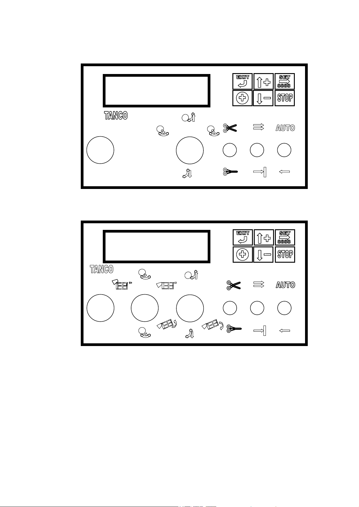
Manual 1080A & 580A TANCO CONTROLLERS Page1 of 28
580A controller version
1080A controller version.
The TANCO wrapper machine controller is an advanced automatic system. It both control and
monitors the moving machine parts and thereby provides for an optimal efficient and safe
machine operation. The system gives detailed instructions and messages via the 40 character
alphanumeric display, enabling the operator to monitor the operation of the wrap machine at any
instant.
The system is equipped with various test facilities, warning messages, error messages and
instructions making the system superior in terms of facilities, service and operation.
Page 2
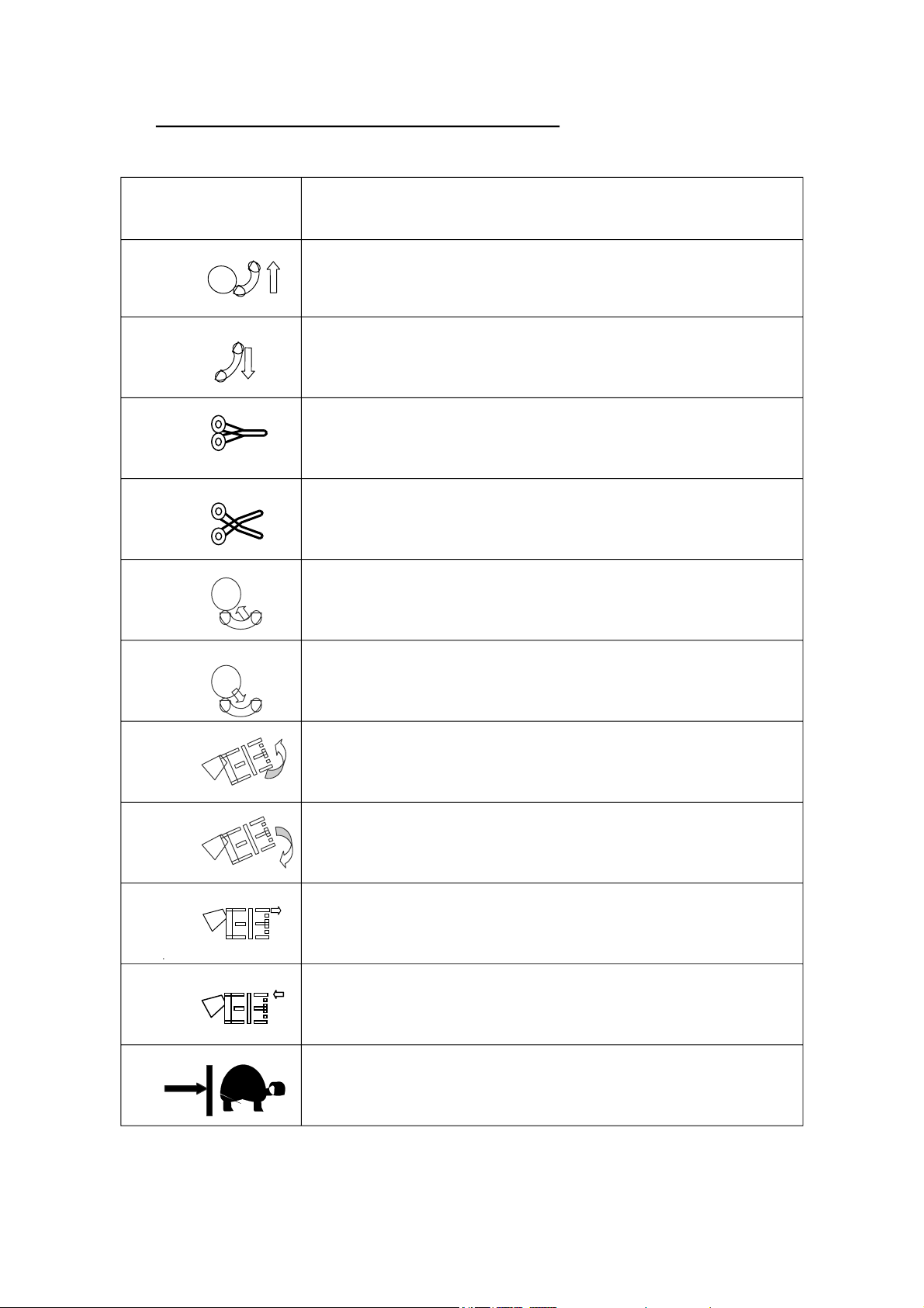
THE DISPLAY UNIT AND PANEL FUNCTIONS
SWITCH
FUNCTIONS
Fig1 Tip off the bale on manual instruction.
Fig2 Tip table back to horizontal on manual instruction.
Fig3 Close cutter on manual instruction.
Fig4 Open cutter on manual instruction.
Fig5 Lower load arm on manual instruction.
EXPLANATION.
Fig6 Raise load arm on manual instruction.
Fig7 Raise elbow on manual instruction ( 1080A only )
Fig8 Lower elbow on manual instruction ( 1080A only )
Fig9 Release bale on manual instruction ( 1080A only )
Fig10 Grab bale on manual instruction ( 1080A only )
Fig11 Turn table seek next position, for load or offload, with
slow speed on manual instruction.
Page 3
Manual 1080A & 580A TANCO CONTROLLERS Page3 of 28
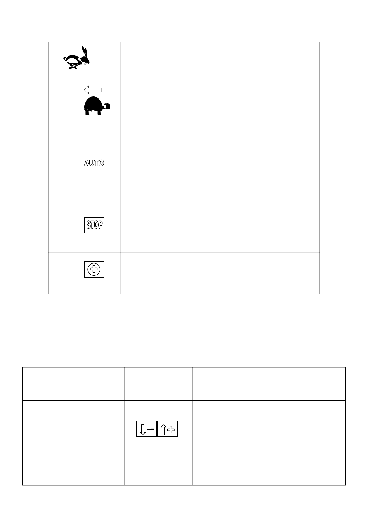
Turn table rotate fast on manual instruction. The turn
table will start in slow mode, accelerate and decelerate to
the slow mode before stopping. The turn table will stop
in any position when the switch is released.
Fig13 Turn table rotate slow in reverse on manual instruction.
The turn table will stop in any position when the switch
is released.
Fig14 Auto start the wrapping cycle. The “auto” command will
start the wrapping cycle at a point defined in the program
setting. This point may be set to, load bale automatically
or start the cycle after the bale loaded automatically or
wait for auto command when the bale is loaded. When
the turntable is running, an auto command will shorten
the program cycle, decelerate on the next passing of the
offload position and stop on the following complete turn.
This cycle is considered completed.
Fig15 Depressing STOP will stop the cycle at any point in the
cycle. An auto command will restart the cycle without
and disturbance of the program cycle and maintain status
of all functions operated manually between the stopping
and the restarting of the cycle.
Fig16 Depressing this button provides for the possibility to
increase the required number of table turns for the cycle
in progression. Each push will increase the turns by one
for that cycle only.
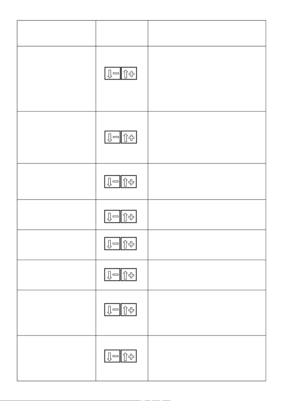
THE DISPLAY MENUES.
At the operator level there is a number of menus enabling the operator to perform various tests
and adjustments to the machine operation. Should adjustments of parameters that not are
accessible to the operator be required, please contact the TANCO dealer or TANCO.
FOR NEXT
DISPLAY INDICATION
VIEW
DESCRIPTION.
DEPRESS
WRAP CYCLE 15: 20 0
BALES: 1 324
The operative display that shows
the commonly most needed
information. The number 15
indicates the actual number of
turntable revolutions at this
moment. The number 20, is the
preset number of turntable
revolutions required to wrap the
bale.
Page 4
DISPLAY INDICATION
ACTUAL RPM 29
ALARM LIMITS: 16 - 30
BALE COUNTERS
PRESS SET TO ENTER
FOR NEXT
VIEW
DEPRESS
DESCRIPTION.
The 16 - 30 indicate the
programmed limits of the turntable
speed. Should the speed exceed 30
rpm or fall below 16 rpm, the audio
alarm will be engaged and the
display will show this message.
The Actual RPM shows the
wrapping speed at any given
instant.
The system has all in all 10-bale
counters. When entering this
display, it is possible to inspect:
Total (sum of all bale counters.)
Machine total (the sum of all bales
ever made on the machine. This is
not a reset able value.)
BALES TOTAL:
XXXXX
MACHINE
TOTAL: XXXXX
COUNTER:
1:XXXX
2:XXXX
3:XXXX
COUNTER:
4:XXXX
5:XXXX
6:XXXX
COUNTER:
7:XXXX
8:XXXX
9:XXXX
WORKING HOURS: 123
MACHINE TOTAL: 798
Bales total. As below but a reset able
function. Machine total displays the
total quantity of bales made on the
machine in total. This is not a reset
able function.
Each counter display contains 3
counters.
Each counter display contains 3
counters
Each counter display contains 3
counters
Displays the number of working
hours of the machine in 1 week,
day or other. ( reset able ) and the
total number of the machine
operating hours. ( not a reset able
facility.)
SETUP ( 580A,TRAILED )
PRESS SET TO ENTER
The operator may here change
some parameters relating to the
machine in order to alter the
machine cycle, sensor setup,
hydraulic flow table selection and
other different options.
Page 5
Manual 1080A & 580A TANCO CONTROLLERS Page5 of 28
DISPLAY INDICATION
WELCOME TO SETUP!
V
FOR NEXT
VIEW
DEPRESS
DESCRIPTION.
ROTATE 90 DEGREES AFTER
TIP FORWARD TO SENSOR:YES
ROTATE 90 DEGREES
AFTER TIP:NO
SENSOR SETUP.
PRESS SET TO ENTER
CUT NOW SENSOR The film cutter will be activated upon
INSTALLED: YES
ROTATE LOAD-POISITION Defines if there is a load position
SENSOR INCLUDED:NO
LOAD ARM UP/DOWN
SENSOR INCLUDED: YES
.
Defines the loading position 90
degrees counter clockwise to the
offloading position.
Defines the loading and off loading
position. To be the same turntable
position.
Entering the sensor setup level.
signal from this sensor.
sensor installed.
In order to achieve automatic loading
of the bale a load arm sensor is
required installed.
The hardware test program is a tool
facility enabling and guides the
operator and service people to test
and inspect almost all functions,
HARDWARE TEST
PRESS SET TO ENTER
switches, sensors and push buttons
on the system. It also contains a
battery supply voltmeter which
automatically will be displayed
should the voltage drop below 8
volt during the operation.
SUPPLY VOLTAGE:xx.xV
LAST DROP:
SENSOR (input) TEST.
PRESS SET TO ENTER
LOAD ARM DOWN,No: 16:0
CUT /HORIZONTAL, NO.17:0
ROTATE ( TIP).NO.18:0
INFRA RED REC.NO.19:0
xx.xV
Displays the instantaneous battery
supply loaded and off load. The last
drop is the lowest voltage supply
measured during current surge when
activating the hydraulics.
Entering the sensor / digital input
test facility.
20:0 MEANS TERMINAL OR PIN
NUMBER 10 , 0 MEANS INACTIVE.
WHEN ACTIVE THE STATUS CHANGES
TO 20 : 1
Page 6
DISPLAY INDICATION
FOR NEXT
VIEW
DEPRESS
DESCRIPTION.
TEST KEYS PRESSED:
XXX.XXX
TEST SWITCHES
ACTIVATED:XXXX.XXXX.XX
TEST RELAYS, 0=OF
XXXXX.XXXXX.XXXXX (12)
TEST. IR REMOTE CONTROL:
00 00 00 00
Enables the testing of each push
button on the control panel.
Enables the testing of each function
switch on the control panel.
Enables the testing of each relay
output function for the hydraulics on
the controller
Enables to test the IR receiver and
transmitter functions.
Operating modes.
The system is designed so that the automatic mode and the manual mode are separated with a
STANDBY MODE. This means that when operated in the automatic mode, all manual
commands are ignored with the exception of the function button for the application of additional
turntable revolutions and the stop button. This also gives the advantage of interrupting and
restarting the cycle at any instant without the system loosing track of the cycle state. All
functions may be manually operated and are only accessible when in standby mode.
All safety criteria are active in both the manual and automatic operation.
STANDBY MODE.
Standby mode is the waiting state between the automatic mode and the manual mode. Standby
mode is automatically resumed when:
1. An automatic cycle is completed.
2. Between cycle steps, Example: The wrapping cycle is completed and the system announces
that it is ready to offload the bale. It is here in STANDBY for an operator command
for
manual or automatic function. An AUTO command will here instruct the machine to
advance to the next logical step in the auto cycle, loading, offloading or start wrapping.
3. Stopping the cycle at any stage will bring the system into standby mode.
MANUAL MODE.
The manual mode, is accessed by activating one of the manual functions switched when the
machine is inactive (standby mode). Any machine function is accessible provided that it is a “
legal “ operation. If the operator requests an illegal function such as offloading a bale while the
turn table is incorrectly positioned, the system will refuse to perform the operation and state in
the display the reason for the refusal, enabling the operator to correct the machine status before
the requested function can be made active.
Page 7
Manual 1080A & 580A TANCO CONTROLLERS Page7 of 28
AUTOMATIC MODE.
The machines are generally operated automatically during the actual wrapping cycle to the
offloading stage. The controlling system will with its standard factory settings, automatically
control the machine with AUTO commands given on the AUTO switch by the operator. For
every program step, the machine has completed, the machine will stop and wait for further
instructions from the operator.
Upon the completion of a wrapping cycle, the system will via the audio alarm and display,
inform the operator that the wrapping cycle has now been completed (program number is equal
to actual number of turntable revolutions, e.g. 16: 16). Now yet an AUTO command will offload
the bale.
SETTING UP THE SYSTEM:
All functions are pre-adjusted from the TANCO factory and commonly the only required
adjustment is the turntable revolutions required.
CYCLE PROGRAMMING.
1: Programming the required number of turntable revolutions. (changing from 20 to 25 turntable
revolutions.)
2: Choosing 1 of the 9 Bale counters.
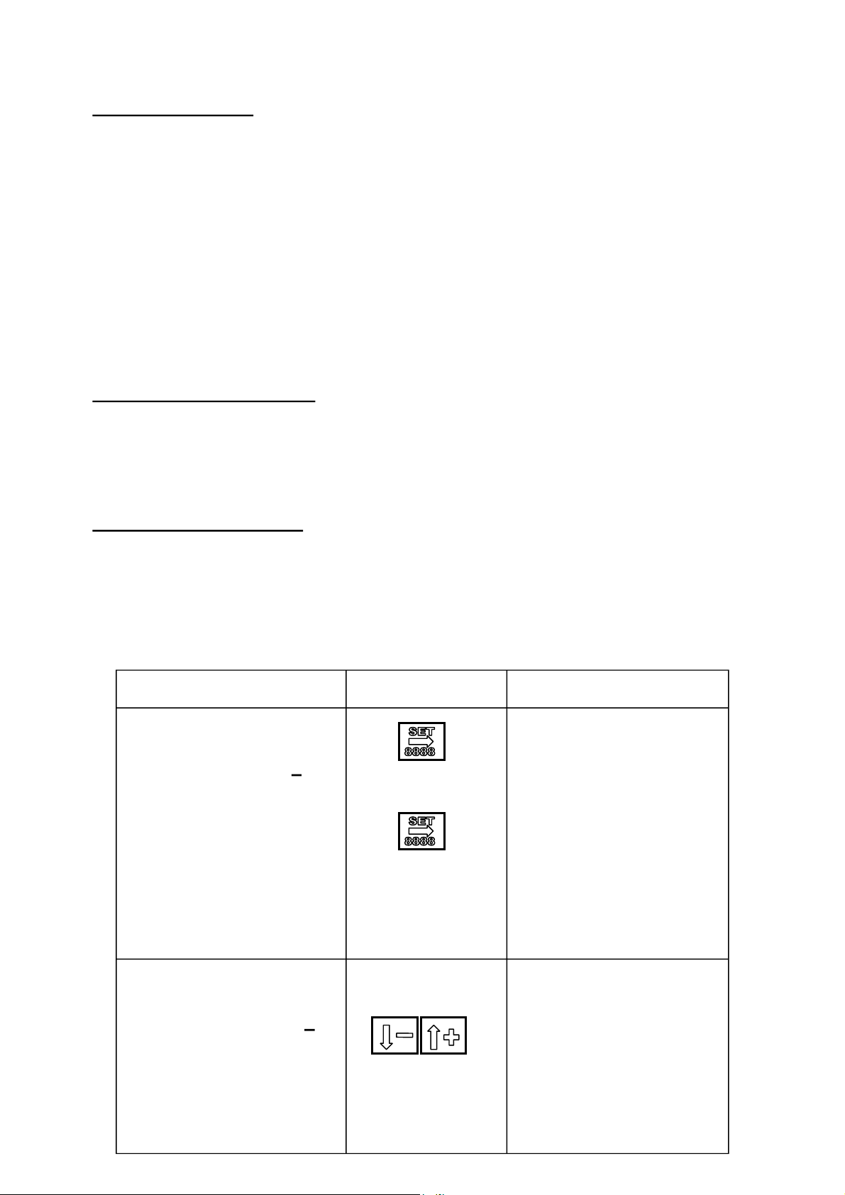
DISPLAY INDICATION.
WRAP CYCLE 0 :
20 0
BALES : 1 324
DESCRIPTION.
To enter programming mode,
push and hold the SET button
for 1 second. The highest
value in the program number
will now flash, meaning that
it may now be changed. As
the number is to be changed
from 20 to 25 turntable
revolutions the number 2 is
not required changed
therefore push “ SET” again
to make the lowest number
value flash. (eg. “0” )
WRAP CYCLE 0 : 25 0
BALES : 1 324
Pushing MENU UP will
increase the number value
between 0 and 9. Similarly
MENU DOWN will reduce
the number value between 9
and 0. In this case push
MENU UP 5 times to change
the number from 0 to 5. Now
the required turntable
revolutions will read 25.
Page 8
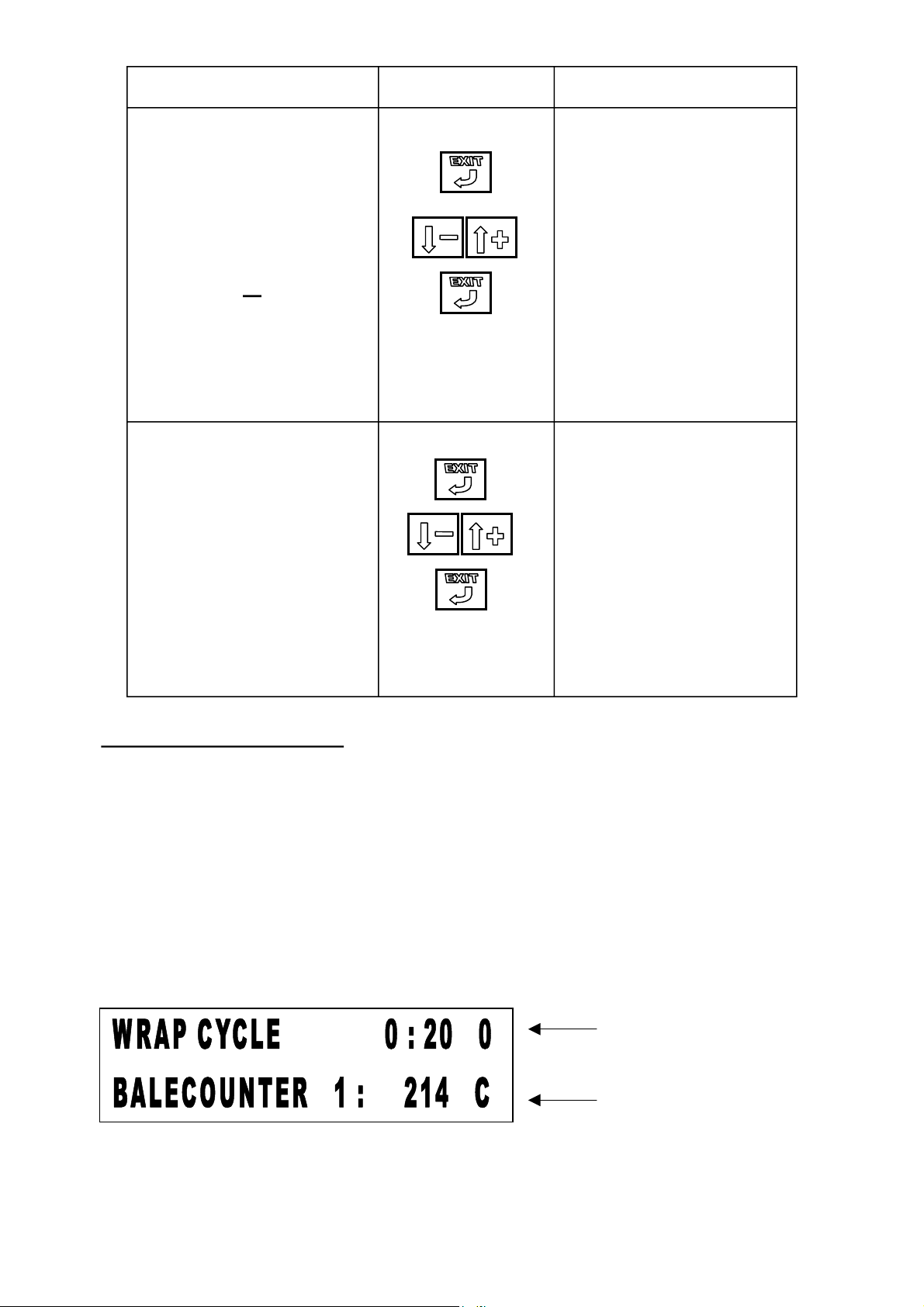
DISPLAY INDICATION.
WRAP CYCLE 0 : 25 0
BALES : 1 324
WRAP CYCLE 0 : 25 0
BALES : 2 125
DESCRIPTION.
To exit programming of
required turntable
revolutions, push the EXIT
button. The bale counter
number ( in this case counter
number 1 ), will flash and
the counter number is now
changeable. The unit
contains 9 individual
counters and 1 counter for
the sum of bales. The MENU
UP or DOWN key is used to
change the number. If the
same counter is to be used
push EXIT again.
It is shown that the counter
chosen, is counter number 2.
This counter contains a
quantity of 125 bales, stored
in the memory. If it is
required to continue the bale
counting from this quantity
and onwards, push EXIT to
return to operative mode, or
ZERO the counter on the
MENU up or DOWN key
and then EXIT to return to
operative.
A TYPICAL WRAP CYCLE .
When work begins the machine is normally transported with the LOADING ARM parked in the
vertical position. The computer registers the lifting of the loading arm as the loading of a bale.
Therefore the display will show that a bale is now located on the table. Therefore the system
will commence wrapping around an empty table, if the AUTO switch is activated when the
loading is down. Therefore it is important that the loading arm is lowered using the joystick and the first bale in the first work cycle is loaded manually only.
Provided the table remains in the loading position ( C position on display ), the system allows
the full up and down movement of the loading arm, however if the system states there is a bale
on the table, movement in the upwards direction will be stopped on the load arm sensor and
lifting the loading arm further is only possible on the 2
nd
attempt.
Bale on table.
Table in Load position.
Page 9

Manual 1080A & 580A TANCO CONTROLLERS Page9 of 28
table
stop
oading positio
activate the positio
g switc
to b
g the
p
DISPLAY.
WRAP CYCLE:
COUNTER 1
A= Offload position.
d=
Between Load and offload
C= Load position.
b= Between Offload and load position
Loss of orientation may occur if the controller suffers power loss during a
wrap cycle and the power loss occurs less than 3-4 revolutions before the
cycle is completed. If there are 2 or more fast speed revolutions left of the cycle, the system
will automatically regain the orientation.
In case of loss of orientation, less than 3-4 revolutions before the end of the wrap cycle, the
will then
Turntable into the offload position and manually offload the bale. Now tip the table to horizontal
Position. The system now shows the correct position (A) on the display and will now seek load
osition ( C ) on the next auto start command.
in L
ERROR MESSAGES ON THE DISPLAY
10 : 20 0
235 d
270 degrees.
n. Now
b
c
90 degrees
nin
.
A
d
h
rin
The machine will in all cases monitor the status of the moving machine parts. Should the
expected position or status of a sensor or device not comply with the safety requirements
specified in the software program, the system will stop the machine cycle at the point where an
error has occurred or when the operator requests an illegal or hazardous command. It will then
via the display announce the reason for the command refusal. When restarting the machine the
system will memorize the point where the cycle was interrupted and continue from the point
where it stopped.
EXAMPLE:
A bale has been wrapped in the manual mode. The operator stops the wrapping cycle with the
turntable away from the offload position. Now if an offload command then is given, the system
will via the display announce that this is an illegal command, writing TABLE NOT IN
OFFLOADING POSITION..”
In order to bring the machine into the correct status the operator must then using the manual
TABLE position command to bring the system back to the logical sequence state.
Similarly if a manual wrap cycle is requested and the table is not horizontally positioned, the
display will write that the table is not lowered to the horizontal position.
LOADING A SECOND BALE ONTO THE LOAD ARM WHILE WRAPPING
.
When loading a bale onto the turntable, and an auto start command is given, the load arm will
automatically return to STANDBY position and the wrapping cycle will automatically begin if
the setup defines this. See SETUP, (
AUTO LOAD BALE WITH LOAD-ARM: YES / NO).
During an auto cycle the operator has permanent manual access to operate the load arm within
limits defined in the program. When the operator approaches the 2nd bale and the load arm is
Page 10
lowered to standby position to collect the 2nd bale, the load arm sensor is activated. When
lifting the bale and the loading arm reaches the STANDBY position., the loading arm sensor
will deactivate the load arm lifting function, preventing collision with the turntable.
After the bale in process is completed an AUTO command will tip off the bale and when the
table again is horizontal, yet an AUTO command will load the new bale from the loading arm
onto the table, again provided the system is defined to (
ARM: YES)
AUTO LOAD BALE WITH LOAD-
VERY IMPORTANT.
It is not recommended that the loading arm is operated during a table tipping down
operation, as there is speed priority on the loading arm causing all other functions to go ½
speed. This may cause the table not to return completely to horizontal position after the off
loaded of the bale.
TROUBLE SHOOTING
.
The system HARDWARE TEST PROGRAM is an operator accessible test facility. Combined
with the display messages, it makes trouble shooting a less complicated matter. It contains the
following:
1. Build in voltmeter that currently is monitoring the battery supply voltage from the tractor
battery.
The voltmeter will simultaneously display:
A. The instantaneous battery voltage (on load and off load)
B. The most resent voltage ( lowest voltage ) caused by activating the hydraulics.
2. SENSOR STATUS.
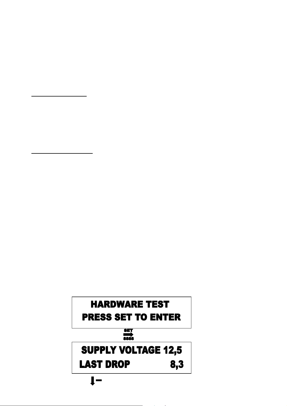
This program enables the operator to test the individual sensors or sensor inputs and is found in
the hardware test program. An active sensor will produce a “1” indication where an inactive
sensor will produce a “0” statement. The display also states the terminal number of the sensors.
Use the MENU – button to locate the below display.
DEPRESS
DEPRESS SEVERAL TIMES TO FIND THE DISPLAY
Page 11
Manual 1080A & 580A TANCO CONTROLLERS Page11 of 28
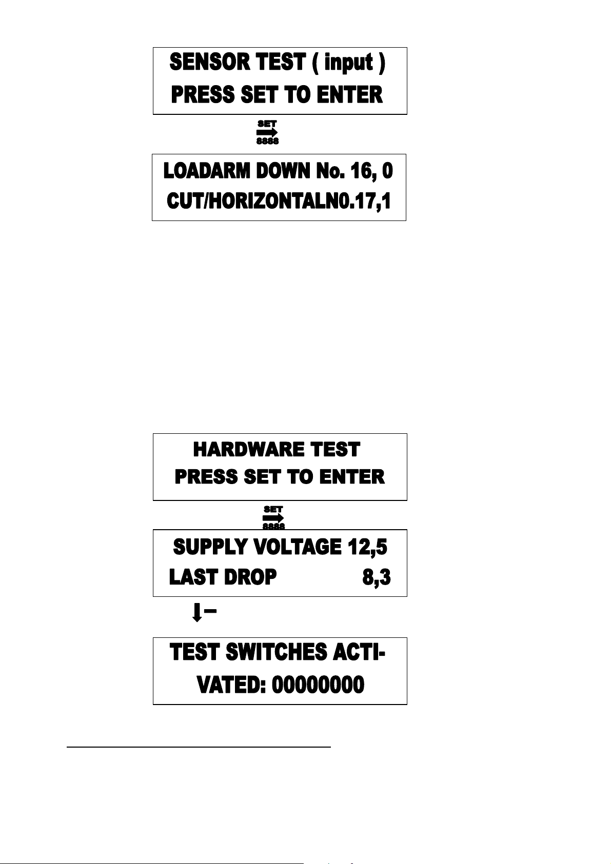
3. TESTING THE CONTROL PANEL PUSH BUTTONS.
When the display below is shown, an activation of the function select buttons will cause the
display to write which button is pushed. The menu and programming buttons maintains their
original purpose and the only button which will show a status change are the set, stop and“ reset
/ extra film layer buttons”.
4. TESTING THE OPERATION SWITCHES.
When the display below is shown, an activation of the operation switches and Start switch will
cause the display to write the status change of the function switches activated.
Use the MENU – button to locate the below display.
DEPRESS
DEPRESS SEVERAL TIMES TO FIND THE DISPLAY
5.RELAY OUTPUT STATUS ( amp pin output.) :
The relay output status: Indicates which hydraulic valves should be active when any operation is
commanded. The operator / serviceman will from this information able to determine whether
there’s a hydraulic or electrical defect. The status of the output is shown as a “1” for active and
a “0” for inactive. The status of the output is shown as the pin number in the AMP connector
and the terminal number in the termination box.
Page 12
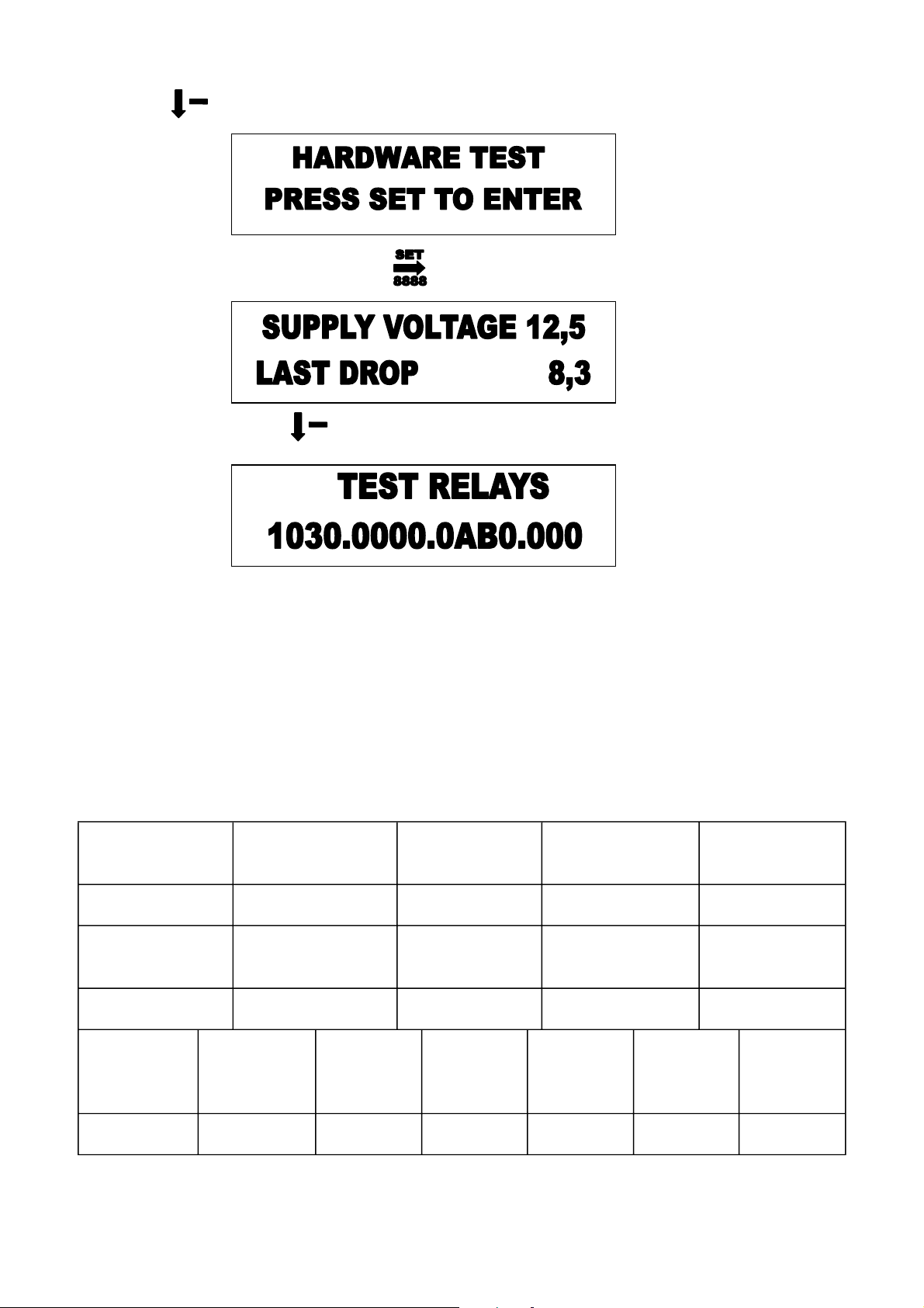
Depress the key several times until the display below is shown.
DEPRESS
DEPRESS SEVERAL TIMES TO FIND THE DISPLAY
When testing a function e.g. Table rotate, a number of outputs are activated simultaneously as other devices
usually are required activated at the same time such as the beacon and slow speed during the start of the
wrapping cycle. In the above example the loading arm down function is active. The output no 1 is the Two
speed valve ( high speed ), 3
rd
. output is the load arm down function, A ( terminal output No.10 ) is the beacon
and B (No. 11 ) is the JD. Output terminal.
Below it is shown which relays, the AMP pin numbers and terminal numbers are related
to.
Amp pin no1.
and term. no.1
Amp pin no.2 and
term. no.2
Amp pin no.3
and term. no.3
Amp pin no.4 and
term. no.4
Amp pin no.5 and
term. no.15
Two Speed valve Load arm down Load arm up Table forward Table reverse
Amp pin no 6,
16and term. no 6.
Amp pin no7,
17and term. no 7.
Amp pin no.8
and term. no.8
Amp pin no.9 and
term. no.9
Amp pin no.10
and term. no.10
Cutter open Cutter close Off load Tip to horizontal JD valve
Amp pin
no.11 and
term no11
Amp pin
no.12 and
term no.12
Amp pin
no.13 and
term. no. 13
Amp pin
no.14 and
term no.14
Amp pin
no.15 and
term no.15
Amp pin
no.16 and
with no.6
Amp pin
no.17 and
with no.7
Rotor lamp close grab Open grab wrist up wrist down Cut close Cut open
Page 13

Manual 1080A & 580A TANCO CONTROLLERS Page13 of 28
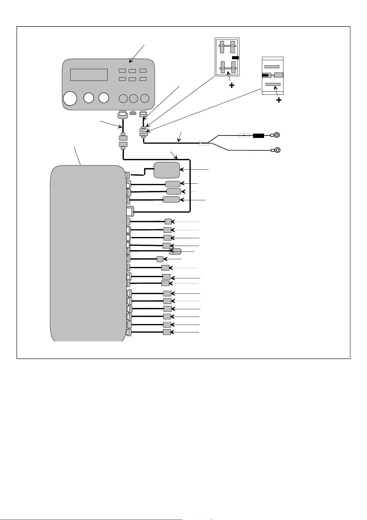
WIRING / TERMINATION / AMP PIN AND FUNCTION TABLE.
Wire and AMP number Terminal number Input & output function
1 1 Table slow/fast
2 2 Load arm down
3 3 Load arm up
4 4 Table forward
5 5 Table reverse
6&16 6 Cutter close
7&17 7 Cutter open
8 8 Tip up
9 9 Tip down
10 10 JD valve
11 11 Beacon
12 12 Close grab
13 13 Open grab
14 14 Elbow up
15 15 Elbow down
16&6 6 Cutter open
17&7 7 Cutter close
18 Ground
19 16 Infra-red sensor signal
20 17 Tip/cut sensor
21 18 Rotate tip position sensor
22 Ground Ground
23 19 Load-arm sensor
24 20
12 volt for Infra-red
receiver
Page 14
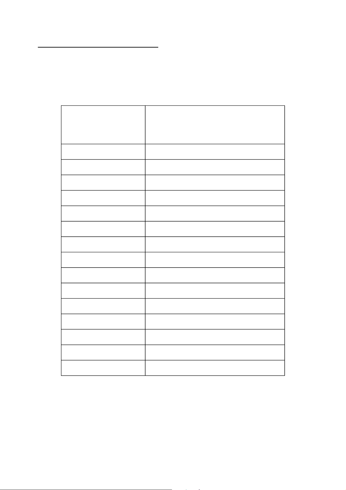
TESTING INDIVIDUAL FUNCTIONS
When testing a function for example turntable rotate, a number of outputs are activated
simultaneously. Also other devices are usually required activated at the same time such as the
beacon, JD and the speed valve for all functions except when wrapping slow at the start of the
wrapping and when the loading arm is raised or lowered during the wrapping cycle.
.
FUNCTIONS
ACTIVATED ON
CONTROL PANEL.
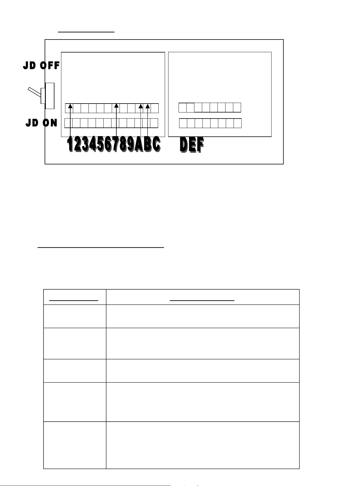
turn table fast forward ( terminal 1000.0000.0AB0.0000 )
load arm down ( terminal 1200.0000.0AB0.0000 )
load arm up ( terminal 1030.0000.0AB0.0000 )
turn table slow forward ( terminal 0004.0000.0AB0.0000 )
turn table slow reverse ( terminal 0000.5000.0AB0.0000 )
cutter close ( terminal 1000.0600.0AB0.0000 )
cutter open ( terminal 1000.0070.0AB0.0000 )
tip up ( terminal 1000.0008.0AB0.0000 )
tip down ( terminal 1000.0000.9AB0.0000 )
DISPLAYSHOWS ACTIVATED
TERMINALS
( terminal 1234.5678.9ABC.DEF )
JD/ general valve ( terminal 0000.0000.0X00.0000 )
rotor lamp ( terminal 0000.0000.00X0.0000 )
close grab ( terminal 1000.0000.0ABC.000 )
open grab ( terminal 1000.0000.0AB0.D00 )
wrist up ( terminal 1000.0000.0AB0.0E0 )
wrist down ( terminal 1000.0000.0AB0.00F )
Page 15
Manual 1080A & 580A
TERMINATIONS
6 Cutter close
5
4 Table forward
3 Load arm up
2 Load arm down
Table reverse
TANCO CONTROLLERS Page15 of 28
A JD valve
9 Tip horizontal
8 Offload
7 Cutter open
C Close grab
B Beacon
Load arm sensor
F Wrist down
E Wrist up
D Open grab
12 volt
IR input
Count sensor
Tip/cut sensor
The cutter open function requires that terminals 1,7,A AND B, present 12-volt on their
respective outputs when the function is active. Note that the A terminal is the JD function with
an inverted output, meaning that the terminal when inactive presents 12 volt on the terminal and
is ground when active.
THE SENSORS AND THEIR PURPOSES
In the user level the sensor setup section is located, here a defect sensor may be disengaged
which otherwise would make it impossible work continue.
SENSOR NAME
Load arm sensor
Determines when it is safe to load the bale onto the table and
SENSOR FUNCTION
commence the wrapping cycle.
turn table sensor,
(load and offload
positioning )
Determines the correct position of the turntable for loading and
offloading. It also counts the number of applied turntable
revolutions and monitors the speed of the wrapping cycle.
Film cut sensor
Governs the correct angular position of the table for the cutting
the film when offloading the bale.
Infrared sensor. Wireless operation of the machine. Typical operating distance
is 30-meter or more. The rotor-lamp time delay engages
automatically when receiving signals from the transmitter and
is only active when using this facility
Important. !
The sensors installed on the machine, should under all normal
circumstances always be engaged to ensure the safe operation
of the machine. The sensor engage / disengage facility is only
to be used in case of a sensor defect, enabling the continuous
operation.
Page 16
BACK/UP MODE
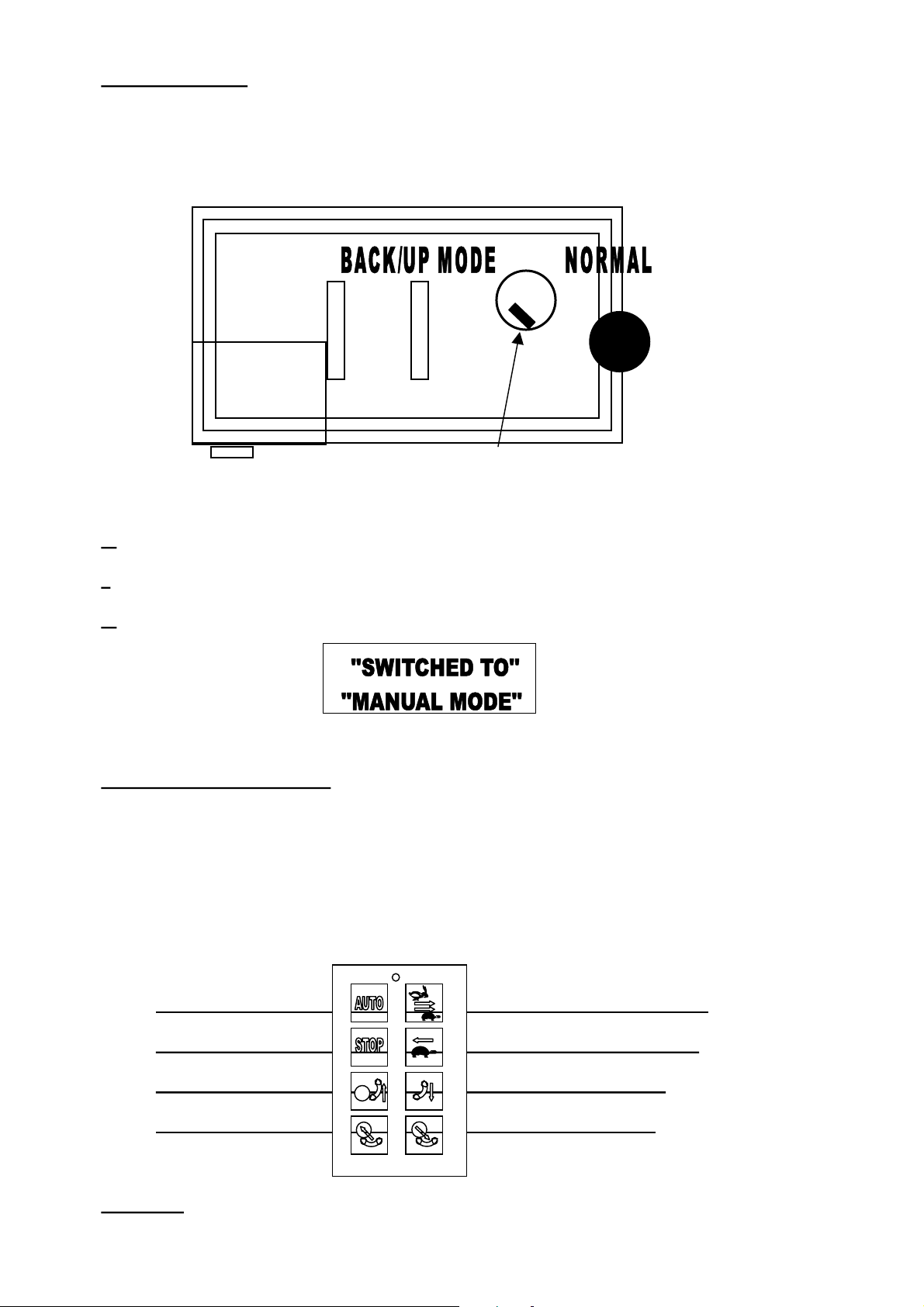
In the event of break down of the controlling circuitry, it is possible to operate the system in
backup mode, bypassing the actual controller, enabling the continuing work.
Computer rear view.
RUBBER CAP.
Back/up switch
1:
Disconnect the power
2:
Remove the rubber cap
3:
Switch from right to left position
The display will now show
THE INFRA-RED SYSTEM
The operational radius of the system is typically 30 to 60 meters, depending on whether
conditions and the state and type of battery used. Worst situations are early morning sunshine
and at sundown, where 20 meters can be expected.
Further! Tractors may be equipped with UV filtered windscreens also reducing the radius
of the system
provided the processor is working
Auto start Forward, slow start.
Cycle stop
Offload bale Tip horizontal.
Load arm down Load arm up.
Warning!
to those, when using the AUTO command on the actual controller panel.
The AUTO function on the handset, will start the machine with equal conditions
Table reverse slow.
Page 17
Manual 1080A & 580A TANCO CONTROLLERS Page17 of 28
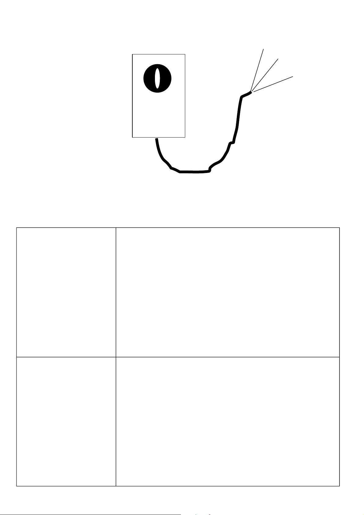
RECIEVER. 1
wire no 1 = 0 volt ( ground)
wire no 2= 12 volt
3 YELLOW
2
wire no 3= signal.
( see drawing of termination box )
DISPLAY ERROR MESSAGES. DISPLAY MESSAGE EXPLANATION.
The load provided by the hydraulic circuit has caused the supply
voltage to drop to a level below the acceptable limit. ( 8 volt.)
VOLTAGEDROP
TO:xx.xV
(any message plus )
TIMEOUT!
1. The tractor generator may be defect.
2. The tractor engine Rpm may be too low for the generator to
charge the battery.
3. The supply cable termination onto the battery may be poor or
dirty.
4. The batter may be defect.
Check terminations and go to the hardware test program to
inspect the battery supply voltage in unloaded condition and
loaded condition.
Indicates that an associated hydraulic function has not been
activated on the controller command. A timeout message means
that a sensor has not received an expected signal within a defined
period.
1. The valve may be defect or hanging.
2. The relay output may be defect.
3. The Hydraulic connector may have fallen off.
4. The cable may be broken.
5. The hydraulic connector may be defect.
6. The sensor is defect, test sensor using test program.
Page 18

Test that the output supply is available on the associated
terminals, Amp pins and hydraulic connector.
NO ROTATE
PULSES
LOAD ARM
NOT DOWN
OTHER MESSAGES MAY
APPEAR AND SHOULD BE
TREATED AS THE ABOVE
ILLUSTRATED
Check that the turntable is rotating, if it does check the sensor
and it’s wiring, if ok, use the same procedure as with timeout
message.
As above.
OVERALL VIEW OF DISPLAYS, VARIABLES AND FACILITIES
OPERATOR LEVEL
ENGLISH. ENGLISH
DISPLAY EXPLANATION. DISPLAY
.
USER SECTION ONLY
Programmable user cycle. Counter 3 are
the bale counter in use at present.( 580A)
Programmable user cycle. Counter 3 are
the bale counter in use at present.(
1080A)
The speed of the turntable is here
monitored at any instant. Should the
speed fall below or increase above the
limits, audio and visual alarm will sound.
The system contains a total of 10 bale
counters, which the operator is free to
choose from. The individual counters are
reset able.
The operator setup level provides the
operator with the possibility to make
minor changes to the machine cycle.
WRAP CYCLE: 0-16 /
BALECOUNTER 3: 345 X
WRAP CYCLE: 0-20 /
BALECOUNTER 3: 345 X
ACTUAL RPM: 22
(ALARM LIMIT: 20-35)
BALE COUNTERS.
Press SET to enter.
SETUP
PRESS SET TO ENTER.
HARDWARE TEST. HARDWARE TEST.
Press SET to enter. Press SET to enter.
OPERATOR LEVEL END. OPERATOR LEVEL END.
Page 19

Manual 1080A & 580A TANCO CONTROLLERS Page19 of 28
SERVICE LEVEL SERVICE LEVEL
Secret entry code for the service level.
Should not be available to the user.
THE DISPLAY MUST BE SHOWING
WRAPCYCLE IN ORDER TO GATN
ENTRY.
ENTERING THE SETUP WELCOME TO SETUP
LANGUAGE CHOISE, The system
program contains instruction sets in 5 LANGUAGE:ENGLISH
different languages.
Setting up the machine model.
All timers and variables specified by
TANCO are stored in a FUNCTION
TABEL. The variables are automatically
transferred onto the standard table when the
machine type is defined to the controller.
The values are changeab1e in the standard
table. Changing machine type will reenter
the FUNCTION TABEL onto the standard
table.
SERVICE CODE: 600
PUSH SET, MENU +,EXIT
SIMULTANEOUSLY.
TYPE:1080A
SQUARE BALE WRAPPER
LOAD DEFAULT VALUES
(RPM, TIME..)NOW: NO
The operator may choose a timer table
suitable to the hydraulic flow delivered by
the tractor or stationary pump. The HYDRAULIC FLOW:
turntable speed displayed during the
operation determines which table should be
used.
Here the alarm limits minimum and
maximum RPM of the turntable are
specified. The audio and visual alarm will
be activated if the speed falls below or is
above these limits.( 580A)
Here the alarm limits minimum and
maximum RPM of the turntable are
specified. The audio and visual alarm will
be activated if the speed falls below or is
above these limits.( 1080A)
The system may be programmed to control WRAPPING COUNTER
various models of the Tanco machines. CLOCKWISE: YES
Working hours, is a timer counter, which
may be used by the operator to monitor the
amount of active, wrapping time performed
this day? This counter may be zeroed.
Machine total is a counter that registers the
total amount of hours the machine has been
working. The counter is not reset able. Both
counters are active when hydraulic power is
applied.
WORKING HRS.:XXXXX.X
MACHINE TOT.:XXXXX.X
HIGH (H)
RPM ALARM LIMIT
LOW: 16 HIGH:31
RPM ALARM LIMIT
LOW: 16 HIGH:26
Page 20

SERVICE LEVEL SERVICE LEVEL
When the display shows this message, the
audio alarm may be switched on/off and the
display contrast may be varied. The display
contrast is also always adjustable directly
on the menu up and down buttons.
maximum contrast is 100 and minimum is
0. The system will always when switched
on pre-adjust to 50% in order to avoid “
empty display.”
Switching the display backlight on/off DISPLAY LIGHT: ON
In case of defect sensor it may be TABLE HORIZONTAL SENSOR
disengaged enabling continues operation. INSTALLED: NO
The film cutter will be activated upon CUT NOW SENSOR
signal from this sensor. INSTALLED: YES
AUDIO & DISPLAY.
Press SET to enter.
AUDIO ALARM: ON
DISPLAY CONTRAST: 100
For systems without load position sensor, 2
turntable magnets are required for position
determination.
Defines if the machine is equipped with a ROTATE LOAD POSITION SENSOR
load position senor. INSTALLED: NO
In order to achieve automatic loading of the LOAD ARM UP/DOWN SENSOR
bale a load arm sensor is required installed. INSTALLED : YES
THE BELOW PARAMETERS ARE
DISPLAYED IN THE CYCLE
SEQUENCE EXCATLY AS THE
MACHINE PERFORMES THE
OPERATIONS.
The amount of time the warning beacon is
active before the hydraulic circuits becomes WARNING BEACON TIME
activated. The beacon timer is only active
when the IR transmitter facility is used
A YES statement will when a bale is
located on the load arm with the load arm
in the standby position upon a AUTO start
command cause the bale to be loaded onto
the table and start the wrap cycle
MAGNETS FOR ROTATE.TIP-
POS.sensor:2
SEQUENCE-SETUP NEXT!
BEFORE START(H): 2.0
AUTO LOAD BALE WITH
LOAD-ARM: NO
The length of time, which the grab
hydraulics is active during the grab bale
sequence.
The lengths of time that the grab hydraulics RAISE GRAP SECTION
is active during the lift grab action. DURATION ( L ) : 3.0
CLOSE GRAP
DURATION( L ):3.0
Page 21

Manual 1080A & 580A TANCO CONTROLLERS Page21 of 28
SERVICE LEVEL SERVICE LEVEL
The amount of time the load arm hydraulics
is to active in the upward movement during RAISE LOADARM
loading. The time is counted from the DURATION (H):5.0
release of the load arm sensor.
The amount of time the grab hydraulics is
to active when positioning the bale on the
turntable.
When the load arm is raised, it will in an
automatic loading cycle pause for the
specified period before returning to standby DELAY (H) : 2.0
position ( sensor level )
The time which the load arm hydraulics is LOWER LOAD ARM
active when lowering DURATION (H) : 0.0
The amount of time the grab hydraulics is
to active when bringing the grab to pickup
position.
A NO statement will here cause the
machine to commence the wrap cycle
automatically when the bale is positioned
on the turntable and the load arm has
returned to the standby position.
The maximum amount of time allowed
without missing rotate pulses, before the
system will stop and announce an error.
RELEASE BALE
DURATION( H ): 4.0
LOAD ARM UP TO DOWN
LOWER GRAP SECTION
DURATION ( H ): 4.0
WAIT FOR START SIGNAL
AFTER LOAD: YES
TABLE PULSE INTERVAL
MAX(s):15.0
If the system does not receive film sensor
signals within this amount of seconds the FILM PULSE INTERVAL
system will stop the cycle and announce the MAX:5.0
error.
This variable eliminates the possibility of
false impulse counting during the turntable
start at the beginning of a cycle.
Slow speed during the wrap cycle ROTATE SLOW DURATION
beginning in seconds. WRAP START (s): 2.0
This value determines the quantity of
turntable revolutions required on the bale
before the film holders releases the film.
The speed of the wrapping is in slow mode
while the holders open and close.
The length of time, which the hydraulics is
active during the film release operation or
the length of time, which the spring
arrangement in the electric cutter is
tensioned.
TABLESTART, SKIP PULSE
DURATION (H): 0.8
REVOLUTIONS UNTIL
FILM RELEASE (H): 2
RELEASE FILM ( OPEN )
DURATION ( H ) : 2.5
The amount of revolutions until the electric
cutter is engaged. ( Not applicable for
hydraulic cutter facility.)
REV. UNTIL ENGAGE
ELECTRIC CUTTER: 9
Page 22

SERVICE LEVEL SERVICE LEVEL
The length of time, which the electric cutter
is to be active during the cutting cycle to
approach the spring release device.
Determines the distance the turntable is
permitted to maintain full speed into the ROTATE FAST, START
final revolution before switching to slow FINAL REV.(s): 0.7
speed.
When the turntable has switched to slow
speed, the slow speed will run for this
period.
If the value here is larger than 0 seconds,
the turntable speed will go from slow speed
to stop and stop for this amount of time
before it restarts in slow speed and
continues to the turntable offload position.
If the answer is NO, the system will
automatically offload the bale when the
cycle is complete. A YES means that the
system awaits an operator START
command for the offloading.
ENGAGE ( CLOSE )
ELECTRIC CUTTER ( H ): 5.5
ROTATE SLOW DURATION
FINAL REV.(s): 0.0
STOP TABLE DURATION
FINAL REV. (s): 0.0
WAIT FOR STARTSIGNAL
BEFORE TIP:YES
The amount of time the slow valve is to
remain active after all functions has
deactivated at cycle completion and
turntable stop. This can help reduce
hydraulic jamming due to backpressure.
A NO statement will allow the turntable to
drift away from its sensor position when the
final signal for offloading position has been AUTO-TIP:NO
received.
If a horizontal table sensor is installed, this
time determines the table position during
the offload cycle for cutting the film.
The length of time the cutter hydraulics is
to be active to cut the film during the
offload cycle or the length of time, which
the electrical cutter is to be active during
the cutting action.
The length of time the table tips hydraulics
is to be active during the offload sequence
after the film is cut..
DELAY DURATION AFTER
TABLE STOP( H ):0.0
CHECK TIP-POSITION BEFORE
IF NO CUT SENSOR:
TIP UP UNTIL CUT (H): 2.0
FILM CUT
DURATION (H): 1.5
TIP UP AFTER CUT
DURATION(H): 2.0
After the table is tipped to the outmost
upright position, it pause for this amount of TIP UPTO TIP
time before it returns to the horizontal DOWN DELAY ( H ) : 0.3
position.
Page 23

Manual 1080A & 580A TANCO CONTROLLERS Page23 of 28
SERVICE LEVEL SERVICE LEVEL
The hydraulics will remain active for this
ADDITIONAL time during the lowering
cycle. The tip up to cutter sensor time is
measured by the system and reused on the
lowering cycle ensuring that the table is
lowered as much as possible.
Typically for the trailed versions the
turntable must automatically return to the
loading position after the bale has been TO SENSOR : YES.
offloaded.
Only applicable on machines with load ROTATE 90 DEGREES TO
position sensor. FORWARD ON TIME : NO
ROTATE 90 DEGREES TO FORWARD
ROTATE 90 DEGREES TO
REVERSE TO SENSOR : NO.
ROTATE 90 DEGREES TO
FORWARD ON TIME : NO
TIP DOWN
DURATION (H):3.5
REVERSE TIME:
This variable can be used in case of defect
load position sensor where it then may be
disengaged and the table may then be set to
return to the position on time. ALSO used
as a film tension release function where the DURATION (H) : 0.0
turntable first turns past the loading
position and then return to the sensor
position.
SERVICE LEVEL END SERVICE LEVEL END
Check physical position, related hydraulics
circuit, sensors, wiring or relay outputs.
Check physical position, related hydraulics circuit, sensors,
wiring or relay outputs.
Check physical position, related hydraulics circuit, sensors,
wiring or relay outputs.
Check physical position, related hydraulics circuit, sensors,
wiring or relay outputs.
Check physical position, related hydraulics circuit, sensors,
wiring or relay outputs.
Check physical position, related hydraulics circuit, sensors,
wiring or relay outputs.
ROTATE 90 DEGREES AFTER TIP
ERROR MESSAGES.
TABLE NOT HORIZONT.
LOADARM NOT DOWN
TABLE NOT IN LOAD POSITION
TABLE NOT IN OFFLOAD POSITION
NO FILM PULSES
NO ROTATE PULSES
PRM LIMITS
MACHINE TOTAL RESET FUNCTION
CODE NUMBER 070.
TOTAL RESET CONTROLLER
( BAL=0 ETC.) NO /YES
Page 24
SERVICE LEVEL SERVICE LEVEL
ENTERING THE REPEAT CYCLE
(DEMO PURPOSE ONLY). THE
DISPLAY MUST BE SHOWING WRAP
CYCLE IN ORDER TO ENTER THE
MODE.
Service level facility only. A yes answer
will cause the machine to repeat all
functions without the instruction of the
operator. The repeat mode can only be
annulled by:
1.Changing the statement to NO.
2.Disconnect the power to the system
ENTERING THE BALECOUNTER
PROGRAMMES
Bales total. As below but a reset able
function. Machine total displays the total
quantity of bales made on the machine in
total. This is not a reset able function.
CODE NUMBER 400. PUSH SET,
MENU+ ,EXIT SIMULTANEOUSLY.
** REPEAT WRAP CYCLE ** WHEN
FINISHED: NO
BALES TOTAL: XXXXX
MACHINE TOTAL: XXXXX
Each counter display contains 3 counters.
Each counter display contains 3 counters
Each counter display contains 3 counters
USER ACCESABLE SETUP LEVEL USER ACCESABLE SETUP LEVEL
Entering the user setup level. PRESS SET TO ENTER.
Defines the loading position. (3-point
linkage or trailed machine.)
Entering the sensor setup level.
The film cutter will be activated upon CUT NOW SENSOR
signal from this sensor. INSTALLED: YES
COUNTER: 1:XXXX
2:XXXX 3:XXXX
COUNTER: 4:XXXX
5:XXXX 6:XXXX
COUNTER: 7:XXXX
8:XXXX 9:XXXX
VELCOME TO SETUP!
V
ROTATE 90 DEGREES AFTER TIP.
SENSOR SETUP.
PRESS SET TO ENTER.
Defines if there is a load position sensor ROTATE LOAD-POISITION
installed. SENSOR INCLUDED:NO
Page 25

Manual 1080A & 580A TANCO CONTROLLERS Page25 of 28
In order to achieve automatic loading of
the bale a load arm sensor is required
installed.
Entering the hardware test program.
Displays the instantaneous battery supply
loaded and off load. The last drop is the
lowest voltage supply measured during
current surge when activating the
hydraulics.
Entering the sensor / digital input test
facility.
20:0 MEANS TERMINAL OR PIN NUMBER
10 , 0 MEANS INACTIVE. WHEN ACTIVE
THE STATUS CHANGES TO 20 : 1
LOAD ARM UP/DOWN
SENSOR INCLUDED : YES
HARDWARE TEST
PRESS SET TO ENTER.
SUPPLY VOLTAGE:xx.xV
LAST DROP: xx.xV
SENSOR (input) TEST.
PRESS SET TO ENTER
LOAD ARM DOWN,No: 16:0
CUT /HORIZONTAL, NO.17:0
ROTATE ( TIP).NO.18:0
INFRA RED REC.NO.19:0
Enables the testing of each push button TEST KEYS PRESSED:
on the control panel. XXX.XXX
Enables the testing of each function TEST SWITCHES
switch on the control panel. ACTIVATED:XXXX.XXXX.XX
Enables the testing of each relay output
function for the hydraulics on the
controller
Enables to test the Ir receiver and TEST. IR REMOTE CONTROL:
transmitter functions. 00 00 00 00
TEST RELAYS, 0=OF
XXXXX.XXXXX.XXXXX (12)
Page 26
(
)
(
)
(
)
(WD)
(
)
(WU)
(
)
(OG)
(
)
(
)
(TU)
(
)
(CC)
(
)
(
)
(
)
()(LU)
(
)
(
)
(
)
(
)
(
)
(
)
(
)
(
)
()(
p
)
(
)
()(OC)
(-)
(TD)
(
p )
(
)
Tanco 1080
(
010-5-0091)
monitor
116-7-0033
010-5-0085
MOM MOM MOM
OFF OFF
MOM MOM MOM
OFF
116-7-0513
(116-7-0032
116-7-0512
(JD)
)
(RO)
(CUT)
(LDD)
(CG)
116-7-0353
116-7-0015
RR
(FR
LD
FS
IR RECIEVER
(003-1-0600
(110-0-4000
110-0-4000
110-0-2500
116-0-0080
116-0-0080
116-0-0080
116-0-0080
o
116-0 0080
116-0-0080
116-0-0080
116-0-0080
116-0-0080
)
16-0-0080
1
116-0-0080
116-0-
00
116-0-0080
)
)
tional
o
)
( not terminated
not terminated
tional with IR
80
)
Page 27

Manual 1080A & 580A TANCO CONTROLLERS Page27 of 28
Wire and
AMP
number
Terminal
number
Input & output
function
RDS function and
wire colors are
stated where
required
1 1 Table slow/fast Table slow/fast
2 2 Load arm down Load arm down
3 3 Load arm up Load arm up
4 4 Table forward Table forward
5 5 Table reverse Table reverse
Termination
changes to be
made in the
termination box
if replacing a
PRE 2000 square
bale controller
with a 2000
controller.
6&16 6 Cutter close Cutter close
7&17 7 Cutter open Cutter open
8 8 Tip up Tip up
9 9 Tip down Tip down
10 10 JD valve JD valve
11 11 Beacon Beacon
12 12 Close grab
13 13 Open grab
White/blue. Spare
wire
Red/black. Spare
wire
14 14 Elbow up Turquise. Ground
15 15 Elbow down Yellow/red. Ground
Terminate in
CG 1080 only
Terminate in
OG 1080 only
Terminate in
RG 1080 only
Terminate in
LG 1080 only
Terminate with
black. All
machine
versions with
16&6 6 Cutter open
Yellow /green
Ground
electric cutter
Terminate with
red. All
17&7 7 Cutter close Blue/black. Ground
machine
versions with
electric cutter
Page 28

Termination
changes to be
Wire and
AMP
number
18 Ground Ground Remain
Terminal
number
Input & output
function
RDS function and
wire colors are
stated where
required
made in the
termination box
if replacing a
PRE 2000 square
bale controller
with a 2000
controller.
19 16
20 17 Tip/cut sensor Tip/cut sensor
21 18
22 Ground Ground used as additional
23 19 Load-arm sensor Load-arm sensor
24 20
25 Ground terminate with 18 Ground
Infra-red sensor
signal
Rotate tip
position sensor
12 volt for Infra-red
receiver
Spare ground
or 22
Orange/blue
Ground
Rotate tip position
sensor
Safety loop, may be
ground wire
Red /blue. Spare
wire
Not used with
system
replacement
 Loading...