


Innovation in Agricultural Machinery
handbook
1400 Autowrap
OPERATOR’S
1400/V.02-10-ENG

Tanco Autowrap - 1400
Operator’s Manual
1
Chapter Contents Page
1 Warning Signs / Stickers 2
2 Introduction 3
3 Technical Specications 5
4 Safety Precautions 6
5 Bale Wrapping 10
6 Machine Setup 14
7 Controller Information 26
8 Operational Features 38
9 Electro-Hydraulics 46
10 Troubleshooting 56
11 Maintenance 61
12 Guarantee 64
13 Declaration of Conformity 66
Table of Contents
- Section 1: Operator’s Manual -

Tanco Autowrap - 1400
Operator’s Manual
2
Read Operators Manual
Prior to using machine
Danger from rotating
Prestretcher
Application of Film
to Prestretcher
70% Prestretch on gears
Don not open or remove
Safety Guards while the machine
is connected to the tractor
Danger from oil splashes
Danger keep hands
clear of sharp blades
Danger stay at a safe distance
whilst machine is in operation
Ensure all nuts & bolts have
been tightened prior to
operating the machine
Ensure machine do not exceed
30 R.P.M.
1. Warning Sings / Stickers

Tanco Autowrap - 1400
Operator’s Manual
3
2. Introduction
Chassis
Wrapping Arm Motor
Dispenser
Drive Roller
Idler Roller
Parking Stand
Lower Linkage Bracket
Emergency Stop Arm
Squeeze Arm
Wrapping Arm
Drawbar
Film Carrier
Film Cutter
Bale Guide

Tanco Autowrap - 1400
Operator’s Manual
4
2. Introduction
Tanco Autowrap Ltd congratulates you on your choice of the TANCO AUTOWRAP 1400 bale wrapping
machine. We are certain you will be satised with the machine, and that you will have the pleasure of your
investment for many years.
The TANCO AUTOWRAP 1400 is an ecient, high capacity bale wrapping machine. Its low centre of
gravity and unique split table design ensures that power consumption is kept to a minimum without
compromising output; this is a patented system.
This machine is hydraulically driven by the tractor’s hydraulic system and is controlled from the tractor
cab by an automatic control unit. The machine is trailed directly behind the tractor for transport and oset
to the right for working in the eld. It loads the bale on the wrapping table in the same direction as it is
discharged from the baler. The wrapped bale can be either dropped conventionally to the ground or with
the tting of an optional ‘End Tip Ramp’ the bale can be dropped on its end.
TANCO AUTOWRAP 1400 is designed to wrap bales of grass, hay or straw, with nominal diameter of
1.1 - 1.5m, and weights up to (1400kg). The machine was developed and has been improved since it’s
beginning in 2008, and is now a very reliable and safe machine with high security built in.
This manual is meant to explain how TANCO AUTOWRAP 1400 is setup, attached to tractor, used and how
it works, and shall together with the spare part's list be a reference for maintenance and troubleshooting.
So take good care of this book; it is a part of the machine.
Read carefully through this manual, and especially the safety instructions, before starting the machine.
Follow the instructions thoroughly, if problems should occur, check the troubleshooting guide to try
to establish the problem. Ask your dealer for advice before you attempt anything that may make the
problem worse.

Tanco Autowrap - 1400
Operator’s Manual
5
Technical Specications 1400 Autowrap
Height 2710mm
Width 2660mm
Length (min.) 3940mm
Weight 1250 kg
Wrapping Arm Speed (Recommended) 30 R.P.M
Wrapping Arm Speed (max) 35 R.P.M.
Maximum Bale Diameter 1500mm
Maximum Bale Weight 1400 kg
Pre-Stretchers 750mm
Hydraulic Connection 1pcs Single Working + Free Return
Oil Pressure 180 bar
Oil Amount (Max / Min) 60 lts/min / 30 lts/min)
Maximum Counter Pressure 10 bar
Electrical Connection 12 V DC
NB: Tanco Autowrap Ltd. reserves the right to modify the
construction and/or technical specications without warning
and without rights to changes on already delivered products
3. Technical Specications

Tanco Autowrap - 1400
Operator’s Manual
6
4. Safety Precautions
Tanco Autowrap Ltd does not take responsibility for damages that may occur to machine, persons or
other equipment, because of the machine NOT being used as described in this manual, or because of the
safety precautions NOT being followed.
Emergency Stop
The Tanco Autowrap 1400 is equipped with a so-called emergency stop on the wrapping arm. This device
stops all functions momentarily, but is per denition not an emergency stop, because it does not shut
down the inputs. But it has the same function, so we have decided to call it an emergency stop in this
manual.
Safety Equipment
Before using the machine, make sure that all guards and covers are securely tted. The machine must not
be operated if a function does not work as described later in this manual.
Become Familiar with the Operations of the Machine
If you are unsure how to operate the machine properly, either use of or maintenance to your Tanco
Autowrap, please contact your Tanco Autowrap dealer.
Adjustments / Maintenance
Turn o the tractor and discharge the oil pressure before performing any adjustment or maintenance on
the machine. Remember that a well maintained machine is a safe machine.

Tanco Autowrap - 1400
Operator’s Manual
7
IMPORTANT!
Always make sure nobody is in the hazard area of the wrapping arm when the machine is in-use.
The machine must not be operated by persons who do not know enough about how to safely operate
the machine, or by persons under the age of 16 years.
Dangerous Areas
Tanco Autowrap Ltd. has given the safety to the operator the highest priority, but it is still impossible to
secure oneself of every danger area on the machine. Therefore we have highlighted below some of the
dangers that can occur when using the 1400 Tanco Autowrap Bale Wrapper.
Impact of the Wrapping Arm
During the wrapping process the arm rotates with a speed of 30-35 revolutions per minute around the
bale. On the arm is mounted a Film dispenser unit with a plastic roll. The speed on this can give a person serious injuries if one enters the working area of the wrapping arm. To reduce this danger we have
mounted an emergency stop device on the wrapping arm; this stops all movement when something
comes in the way of it. It is very important that this protection always works and that it should not
under any circumstances be disconnected.
Squeeze Danger Between the Main Frame & Wrapping Arm
As explained earlier, we have a wrapping arm with a Dispenser and a plastic roll. During every revolution the wrapping arm passes the main frame. Here there may occur a squeeze danger if a person
stands to close to the main frame when the wrapping arm passes. The distance between the main
frame and the wrapping arm is not large enough to give place for a person. Between the pre-stretcher
and the bottom frame there can also be a squeeze danger.
4. Safety Precautions
Tanco Autowrap - 1400
Operator’s Manual
8
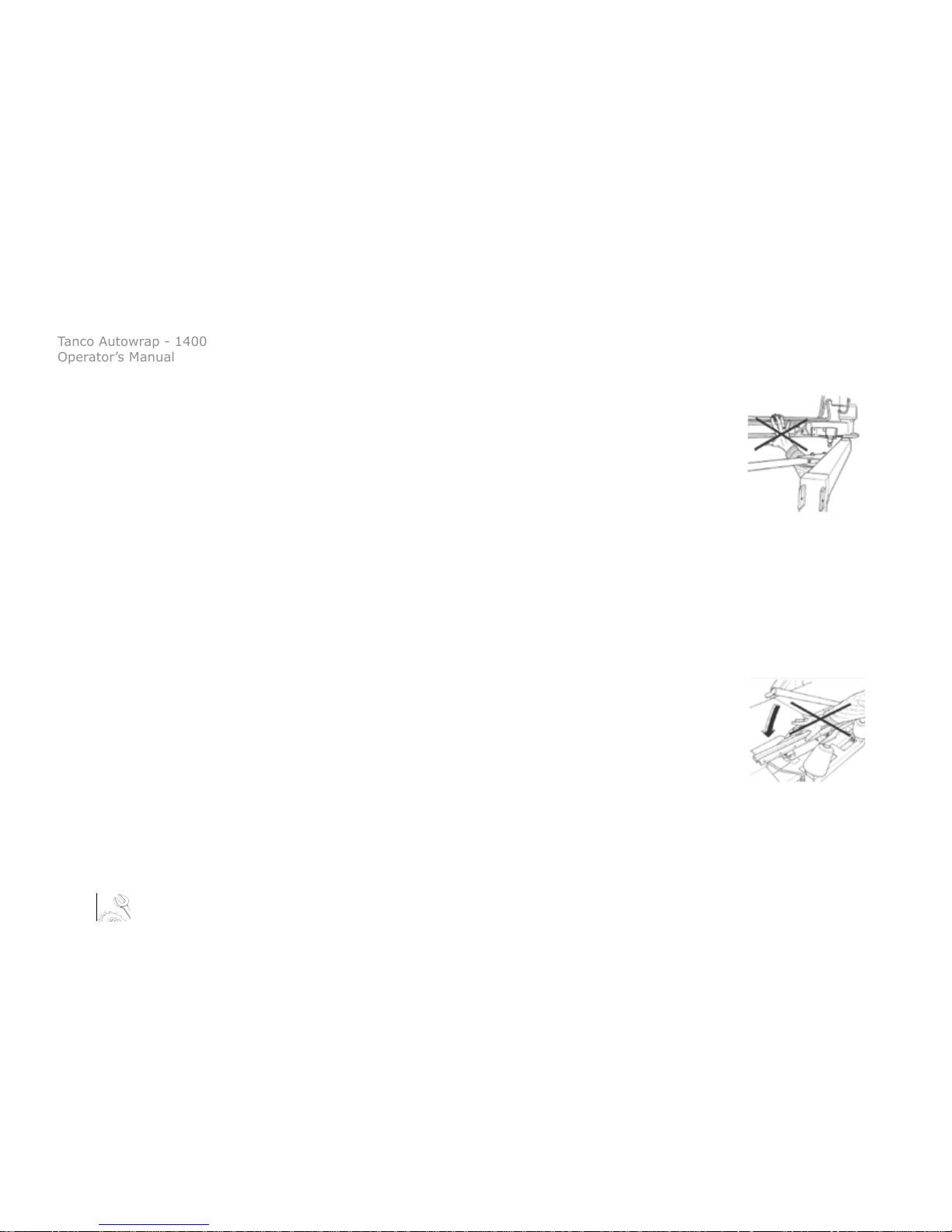
4. Safety Precautions
Fig. 1
Fig. 2
Squeeze Danger Between the Stationary Arm & Wrapping Arm
During the main wrapping process the wrapping arm moves around a stationary arm. Every
time the wrapping arm passes the stationary arm there is a squeeze danger that can be
dangerous for the ngers. The distance between the stationary and the wrapping arm is
between 25-40 mm. (See Fig. 2).
Impact of Bale Squeeze Arm
During the bale loading process the bale squeeze arm moves both vertically and horizontally, beware of
the danger and keep clear of this area whilst the machine is running.
Impact Danger when Machine is being changed from Transport to Working Position at the Drawbar
When the machine is being changed from transport to the working position it rotates out to the right
and when it is being put back into transport it rotates back to the left, beware of the danger and keep
clear of this area whilst the machine is running; especially if the squeeze arm is in the open position.
Squeeze Danger Caused by Plastic Automation
At the end of the wrapping process the plastic is cut and held tight until the start of the next
wrapping process. When the cutter arm moves down to lock the plastic, there can occur a
squeeze danger between the cutter arm and the cutter holder. The cutter blade that cuts the
plastic is very sharp; ensure to keep hands away from the cutter. (See Fig.2).

Tanco Autowrap - 1400
Operator’s Manual
9
4. Safety Precautions
Connecting heavy working implements often has an overall negative eect on the tractor’s driving
and braking capacity.
Transporting
When transporting on a public road there are certain safety measures that must be taken:
1. Ensure the machine is in the transport position.
2. Ensure the squeeze arm is fully closed.
3. Ensure that the wrapping arm is not parked overhanging the sides of the machine.
4. Ensure that the lights are connected and functioning correctly
5. It is recommended that the lm rolls be taken o the dispensers for road transport and put on
the lm carriers on the drawbar. This reduces stress on the machine and reduces the danger of the
rolls being accidently falling o on the public road.
6. The machine is wide (2660mm) even in transport position, be aware of this especially on narrow
roads.

Tanco Autowrap - 1400
Operator’s Manual
10
5. Bale Wrapping
Bale Wrapping Principles
The advantages of round bale silage are many, and include fewer feed units, a exible harvesting system,
large capacity and the possibility of selling feed units.
In principle, the same fermentation processes occur whether the fodder is placed in a silo or pressed into
bales and packed in plastic, i.e. lactic acid fermentation in anaerobic conditions. The oxygen in the bale
must be exhausted before fermentation begins.
The grass should be dried to approximately 30-40% solid content. The solid content can be determined
by twisting the grass by hand. If drops of liquid are forced out of the grass, the solid content is less than
25%. Low solid content (wet grass) can lead to increased butyric acid fermentation if preservatives are
not added to the grass. If the solid content is too high, (over 50%), normal fermentation will not take
place and there will be enough oxygen in the bale to produce mould fungus.
The Baler
It is vital that the baler produces compact, well-formed bales, as misshapen bales can be dicult to wrap.
Wrapping will also often take longer, thereby increasing the amount of plastic used.
Dicult Bales
When a misshapen bale is wrapped, it will have a tendency to move outwards or inwards on the roller. If
the bale begins to move outwards, the machine must be lifted slightly at the rear edge to get the bale to
rest against the support roller on the main frame. It can therefore be useful to use a hydraulic top link to
make this adjustment easier. (See Chapter 5; ‘Hitch Height’).

Tanco Autowrap - 1400
Operator’s Manual
11
5. Bale Wrapping
If the bale to be wrapped is conical you must ensure that the sharp end is pointed at the tractor. It
will then be easier to get the bale to lie correctly during packing. It is easy for such a bale to “turn”
forward in the direction in which it is pointing, and therefore lie against the support rollers. If the
bale is lying on a slope it must be picked up from the lower side. A hydraulic top link will again be
advantageous.
Types of Plastic
A good type of plastic with good adhesive properties, and which is recommended for bale
wrapping, must be used. The thickness of the plastic foil should be at least 25 µ. (25/1,000 mm). In
order that the plastic tightens suciently around the bale, it is stretched before being wrapped,
so it is somewhat thinner when it is put on the bale. With short-term storage (up to eight weeks) it
is recommended that bales have a minimum of four layers of plastic at the thinnest points, with at
least 52-53% overlap.
For long-term storage, or when the grass is wet when it is wrapped, the bale should have 90-100 µ
plastic (six layers) and the same amount of overlap. If thinner plastic is used, more layers should be
applied. If it is very hot the plastic will be stretched further, and more layers should be applied. It is
better to have slightly too much than too little plastic on the bale.
From experience, light colored plastic produces slightly lower temperatures within the bale, and
tends to improve feed quality.

Tanco Autowrap - 1400
Operator’s Manual
12
Storage Location
Care should be taken in nding a suitable location for the storage of bales. The storage location
should preferably be prepared before the bales are laid out. An elevation close to well-drained roads is
recommended. If the wrapped bales are simply placed on stubble there is a danger of the plastic being
pierced. A tarpaulin or a thin layer of sand should therefore be laid where the bales are to be stored over
the winter.
Bales should be stored in the shade as far as possible. This reduces the danger of air leakage in the bales.
A bale which is stored in sunlight and which therefore undergoes greater swings in temperature “pumps
in” a great deal of air in comparison to a bale stored in the shade. According to “Teknik for Lantbruket”
[Technology for Agriculture] in Sweden, a bale stored in the shade has only 40% of the air leakage of a
bale which is stored in sunlight.
Stacking / Protection
If bales are hard and well formed, they can be stacked vertically, but loose and misshapen bales with low
solid content should not be stacked higher than one layer, as this could easily cause deformity and the
danger of runo will be increased.
Bales can also be stored on their sides. The layer of plastic is thicker here, providing greater protection
against piercing.
Bales should be covered with a tarpaulin or a ne-mesh net to protect against birds and small rodents.
If the plastic is pierced, it must be sealed with weatherproof, hard-wearing tape, preferably under the
outermost layer of plastic. Ensure that the hole is adequately sealed.
5. Bale Wrapping

Tanco Autowrap - 1400
Operator’s Manual
13
For Best Wrapping Results...
1. Harvest the grass early.
2. Ensure the grass is dried out to 30-40% solid content. If there is a danger of rain, bale and wrap the
grass anyway.
3. Take care not to mix any earth in with the grass.
4. Use a baler that produces even, rm bales. Bales 1.2mtrs in width and with a diameter of 1.2-1.5mtrs are
preferred sizes.
5. Wrap the bales as soon after baling as possible; never more than two hours afterwards.
6. Use a good plastic type, applying six layers of plastic. This removes the need to use preservatives.
7. Store bales in the shade to reduce the danger of air leakage.
5. Bale Wrapping

Tanco Autowrap - 1400
Operator’s Manual
14
6. Machine Setup
Mounting of the Machine
Be careful! There is a danger of being crushed when working implements are tted and connected.
Carry out the tting procedures slowly and carefully, and use separate and approved lifting equipment
to make the work easier. Note the section on safety precautions and pay attention to the various safety
decals displayed on dierent parts of the bale wrapper.
Attaching to the Tractor
The 1400 can be either connected to the tractor lower links using Linkage Attachment or by removing
this it can be attached to the tractor hitch using the Hitch Eye.
If the lower link bracket is used the Hitch Eye should be attached in the lowest position; this will allow
greater movement.
If attached to the tractor hitch it is recommended that the machine is attached to the Clevis Hitch rather
than the Pick-Up Hitch. This gives more clearance between the Drawbar and the tractor’s back wheels.
The Drawbar does not run directly behind the tractor. In transport the Drawbar runs nearer the left wheel
so the minimum turning circle to the left is reduced. In the working position this is the case for turning
to the right. When the machine is attached to the tractor the Drawbar Leg must be folded up to the
Drawbar by removing the Drawbar Pin; swing the Drawbar Leg upwards and t the Drawbar Leg Pin to
Position B. (See Fig. 3 Overleaf).

Tanco Autowrap - 1400
Operator’s Manual
15
Drawbar Leg (Stored Position)
Drawbar Leg (Operating Position)
Drawbar Leg Pin
Drawbar Leg Pin Position B
Hitch Eye
Hitch Eye Fixing Bolts
Lower Linkage Attachment
Lower Linkage Pin
Fig. 3
When attached to the tractor the machine should sit level, at this the squeeze arm will have 10cm
approximate clearance with the ground when in the fully lowered position. Set linkage height to achieve
this.
Adjust the linkage stabilizers to limit the lateral movement.
If attached to the hitch change the hitch eye mounting position to set the correct height.
Ensure the Hitch Eye Fixing Bolts are securely tightened.
6. Machine Setup
Tanco Autowrap - 1400
Operator’s Manual
16
1400 Control Box
The control unit consists of the emergency stop button, a control cable, a
fuse and a battery cable. The control unit should be attached to a suitable
place in the tractor cab using the suction pad provided.
The Remote Control Unit is not Shock Proof, make sure that is fastened to a
soft pad that secures a non-vibratting foundation.
Electrical Connection
The electric supply for the machine’s remote control and electro-hydraulic
components must come directly from the tractors’ 12 volt battery.
The electric wires from the battery must have an area measurement of min.
2,5 mm2. Connection to other contacts on the tractor can cause risk of
malfunction and is not recommended.
Note:
Brown leader goes to the Battery’s Possitive Pole
Blue leader goes to the Battery’s Negative Pole
6. Machine Setup

Tanco Autowrap - 1400
Operator’s Manual
17
Hydraulic Connection
The hydraulic hoses between machine and tractor are equipped with 1/2” ISO Male Quick-Couplers.
Ensure the oil pressure has been discharged before you connect the oil hoses using the tractor’s
hydraulic lever.
To make sure that the bale wrapper works properly, the tractors’ oil pressure has to be at least 180 bar.
The oil ow should be 15 - 25 liters per minute. The return pressure on the return must be as low as
possible, and not exceed 10 bar. This should be measured with a gauge. It is recommended to use one
single-working hydraulic outlet and arrange a free return circuit to the oil tank.
If you are unsure of what oil pressure the tractor gives, or what oil pressure the bale wrapper receives,
please contact your machinery dealer. Generally all tractors have got some counter-pressure in their
hydraulic return systems. Some tractors have more than others.
Note:
The Hose with the Red Cap shall be connected to pressure ‘P’ and Hose with Blue Cap to the return ‘T’.
6. Machine Setup

Tanco Autowrap - 1400
Operator’s Manual
18
Open & Closed Center Hydraulics
The 1400 hydraulic system can be set up for tractors with Open or Closed Center Hydraulics.
Open Centre Hydraulics
Most tractors have a hydraulic system that gives a continuous output which ows through the valve on the
machine and back to tank when no function is operating (Open center).
Note:
The TANCO AUTOWRAP 1400 is set-up for open centre on leaving the factory.
Close Centre Hydraulics
Some tractors (John Deere) have a hydraulic system that require the valve on the
machine to allow no ow when no function is operating (Closed Center).
The hydraulic valve can easily be congured to operate in this way.
Simply push and twist the Manual Override on the Master Valve. (See Fig. 4)
Push & twist to lock for Closed Centre
Fig. 4
6. Machine Setup

Tanco Autowrap - 1400
Operator’s Manual
19
LS Hydraulics
Many modern tractors have a “Load Sensing” (LS) Hydraulic System. This is most ecient as the pump
remains on standby, pumping no oil until it gets a signal from the machine. It is possible to run this
machine on a load sensing tractor with the standard valve.
Congure the valve for open centers and if possible adjust the ow from the tractor to give ~30 lts/
min. This however means that the tractor is constantly pumping and you do not get the benet of the
eciency of your load-sensing pump.
Tanco Autowrap strongly recommend that if you are running the machine on tractor with LS Hydraulics
you t the optional Load-Sensing Block (see Hydraulic Circuit). With this block tted a Load sensing
signal is transmitted in the form of hydraulic pressure via a hose for the LS Port on the LS Entry Block to
the LS Connection on the tractor.
Note:
The LS Entry Block can be congured also to run on any other hydraulic system, open or closed center.
6. Machine Setup

Tanco Autowrap - 1400
Operator’s Manual
20
Check List:
Before using the machine it is recommended to follow this check list:
1. Make it a habit to discharge the oil-pressure before connection or disconnection of the hydraulic
hoses. (By operating the hydraulic control lever inside the tractor). (Use the tractors hydraulic control
lever).
2. Return-oil should be led directly to tank. Beware that if the counter pressure is too high, the security
valve on the main block will release some oil. (See Chapter 9).
3. Hose with BLUE CAP = RETURN OIL.
4. Hose with RED CAP = PRESSURE.
5. Tie up loose hoses and Connection Cables so that no squeeze damages occur.
6. Remove the locking bolt that holds the wrapping arm to the frame during transport.
7. Start the tractor and try out the functions. A bale is not required for this test.
8. Check all connections, hoses and couplings. If there is any oil-leakage, it should be rectied
immediately.
6. Machine Setup

Tanco Autowrap - 1400
Operator’s Manual
21
If any problems should occur, it is most likely that the failure is in the quick-couplers on the tractors
pressure and return-connections.
Make sure that both the male and female-couplers opens properly for the oil ow, check these carefully.
The best thing to do is to exchange the quick-coupling on the return side and arrange a “free return”.
Your Tanco Autowrap Bale Wrapper has been tested in practical operation in approximately 2 hours at
the factory.
6. Machine Setup

Tanco Autowrap - 1400
Operator’s Manual
22
Emergency Stop (See Fig. 5)
This machine is equipped with a safety guards on the Wrapping Arms,
and its operation must be tested before work itself is started.
The Emergency Stop is to prevent the Wrapping Arm from damaging
people and objects, when the machine is started and during the
wrapping process.
When the Safety Arm that activates a small electric switch, which gives a signal to the
Control Box to start the Emergency Stop.
When testing this function, start the Wrapping Arm, hold out an arm or any obstacle.
The wrapping arm shall now stop before it hits the arm. Great care must be taken
when testing this function. To restart the machine the obstacle must be removed
and the arm must be returned to its original position. The Auto Switch on the control
box must be activated again. The wrapping may start again.
IMPORTANT!
GIVEN THE VELOCITY AND MOMENTUM OF THE ARM IT IS IMPOSSIBLE TO STOP THE WRAP ARM
IMMEDIATELY. THE EMERGENCY STOP ARM IS PROVIDED TO HELP REDUCE THE RISK OF SERIOUS INJURY
AND GREAT CARE MUST BE TAKEN WHEN OPERATING THIS MACHINE.
Electronic Switch
Safety Arm
Wrapping Arm
Film Dispenser
Fig. 5
6. Machine Setup

Tanco Autowrap - 1400
Operator’s Manual
23
Mounting of Plastic Film (See Fig. 6 & 7)
When loading a plastic roll, rst ensure the Top Cone is pushed up to the latched
position, then push back the Dispenser Insert until held in position by the
Bottom Latch.
Place the Roll on the Bottom Cone and release the Top Latch.
BEWARE OF FINGERS!
Pull the lm between the rollers on the Dispenser Insert in the direction of the
arrow, as shown below. (See also the sticker on the dispenser).
Release the Bottom Latch and allow the rollers to lie against the roll of lm.
Pull the lm from the roll and tie it to the bale.
Top Latch
Bottom Latch
Dispenser Insert
Bottom Cone
Top Cone
Fig. 6
Fig. 7
6. Machine Setup

Tanco Autowrap - 1400
Operator’s Manual
24
Adjusting the Height of the Dispenser
The standard lm dispenser is designed for 750mm lm.
The plastic lm should hit at the middle of the bale wrapped (Fig. 8), and therefore it can be necessary to
adjust the height of the pre-stretcher (See Fig. 9).
Height Adjustment
Fig. 8
Fig. 9
6. Machine Setup

Tanco Autowrap - 1400
Operator’s Manual
25
Gear Bolt
Pos. 1 Pos. 2
Tanco Dual Stretch Dispenser
All Tanco Autowrap machines are supplied with a patented dual stretch gear
system. This system enables a quick change of stretch levels on the Film
Dispenser.
If the Gear Bolt is tted in Position 1 (See Fig. 10), the top set of gears provide
the stretch @ 70%. By removing the Gear Bolt from Position 1 and tting it
in Position 2, the bottom set of gears become the stretch gears giving 32%
(for prestretched lm) or optionally 55% (for use in hotter climates or with
square bales).
Fig. 10
Inner Gear Outer Gear % Stretch
60 Tooth 35 Tooth 70%
58 Tooth 37 Tooth 55%
54 Tooth 41 Tooth 32%
Tanco Dispenser Gear Combinations
6. Machine Setup

Tanco Autowrap - 1400
Operator’s Manual
26
7. Controller Information
Introduction
The Tanco Autowrap Bale Wrap Controller enables the operator to monitor and control the operation
of the bale wrapper at any stage of the wrapping cycle. The controller is designed for models: 1400 and
1814 table type wrappers.
There are 2 operating modes – Automatic and Manual. The Automatic Mode permits ‘one-touch
wrapping’ to ease the workload on the operator. The controller is fully programmable to optimise
wrapping performance. Bale counts are automatically logged in any one of 10 selectable memory stores,
in addition to a grand total memory store.
IMPORTANT SAFETY INFORMATION!
Please read and understand the instructions for using this controller before operating the machine.
This controller is tted with a push-button type On/O Emergency Stop switch. Always ensure the
controller is switched OFF via this switch before attempting any adjustment or maintenance to the
machine.
Please follow ALL other safety instructions given in the manufacturers’ Operator’s Manual for this
machine.
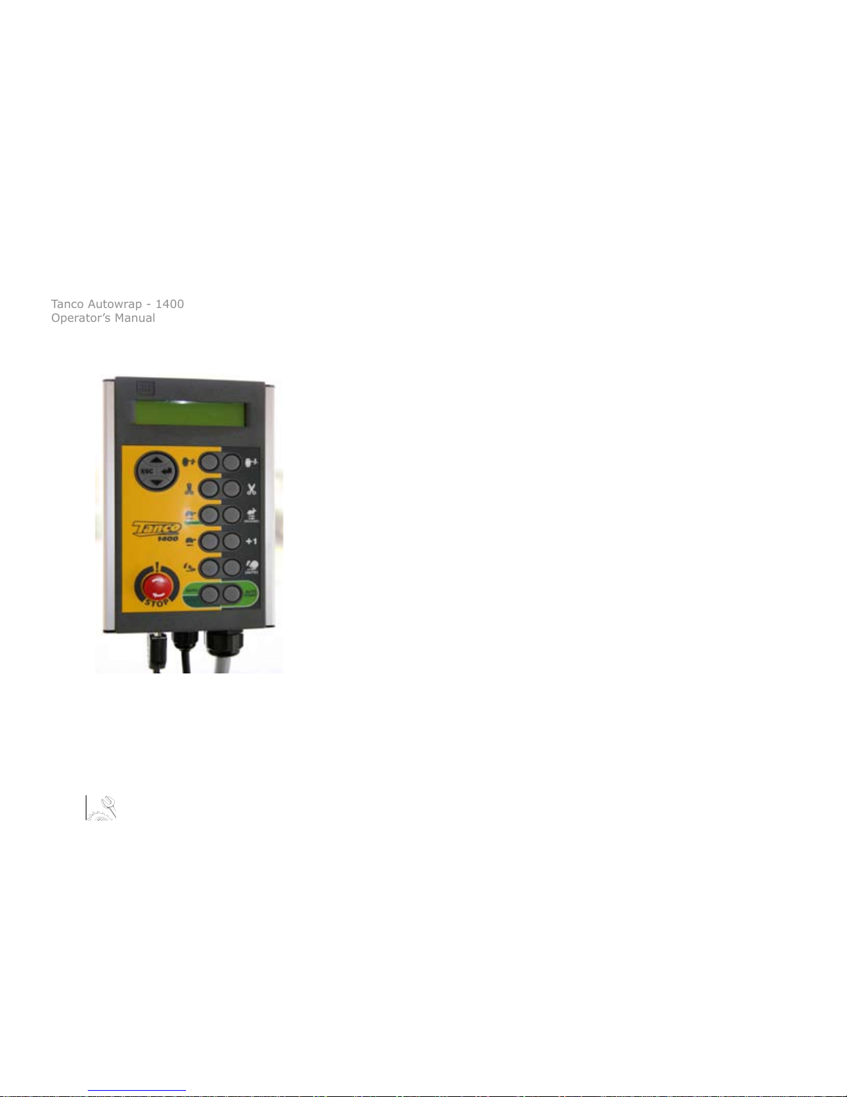
Controller Main Operating Functions & Display
The principal instrument features and operating functions of the Controller are shown in Fig. 11 overleaf.

Tanco Autowrap - 1400
Operator’s Manual
27
Display; Shows in normal working mode:
- Current No. of Wraps
- Target No. of Wraps
- Wrapping Speed (R.P.M)
- Bale Total (10 Separate Stores)
- Grand Total No. of Bales
- Mode: M (Manual) / A (Automatic)
R1 - Move Drawbar to Working Position
R2 - Release Film Grip
R3 - Fast Wrap / Resume Wrap (After Manually Pausing)
R4 - Adds 1 Wrap to Current or Next Bale
R5 - Bale O-load
In ‘M’ (mode): Tips Bale
In ‘A’ (mode): Starts Auto O-load O-loads Bale, lowers front to load position &
returns rear roller to working position
R6 - Start Automatic Wrapping Cycle; press STOP
switch to stop cycle
4-Way Menu Switch:
- Set No. of Wraps
- Change / Reset Bale Sub-Total
- Access Operator Setup Menu
- Access Technician Setup Menu
L1 - Move Drawbar to Transport Position
L2 - Cut & Grip Film
L3 - Slow Forward to Park Position /
Controlled Stop during Wrapping
L4 - Reverse Wrap Arm
L5 - Bale Loading
In ‘M’ (mode): Returns rear roller to working position
In ‘A’ (mode): Starts Auto Load - Squeezes Bale, Loads
Bale & returns rear roller to working position
Power On/O / Emergency Stop
L6 - Select Operating Mode: ‘M’ or ‘A’
Fig. 11
7. Controller Information

Tanco Autowrap - 1400
Operator’s Manual
28
In ‘M’ mode: Load Up
In ‘A’ mode: Starts Auto Load (Auto Hand Cont. : ON)
In ‘M’ mode: Squeeze In
In ‘M’ mode: Squeeze Out
In ‘A’ mode: Starts Auto Wrap (Auto Hand Cont. : ON)
In ‘M’ mode: Load Down
In ‘A’ mode: Starts Auto O-load (Auto Hand Cont. : ON)
Operation
Operation in Automatic mode
The automatic sequence is made up of three sections: Loading, Wrapping and O-loading.
The controller comes initially set so one press of a button automatically loads the bale, a second press
runs the complete wrapping cycle and a third press automatically o-loads the bale.
It is possible to set the controller so one button press runs the complete cycle, see ‘Changing Default
Automatic Sequence’.
As initially set three buttons on the controller are used to start each section of the sequence, see points,
3, 5, and 7 below.
Fig. 12
7. Controller Information

Tanco Autowrap - 1400
Operator’s Manual
29
Operation
Operation in Automatic mode
The automatic sequence is made up of three sections: Loading, Wrapping and O-loading.
The controller comes initially set so one press of a button automatically loads the bale, a second press
runs the complete wrapping cycle and a third press automatically o-loads the bale.
It is possible to set the controller so one button press runs the complete cycle, see ‘Changing Default
Automatic Sequence’.
As initially set three buttons on the controller are used to start each section of the sequence, see points,
3, 5, and 7 below.
1. ‘A’ on the display indicates that the controller is set in Automatic mode. If not press (L6) to select.
2. The automatic starts with the wrap arm in the park position, that is with the wrap arm magnet parked
under the sensor, the load arm down and squeeze arm in the fully open position.
3. Press (L5) to start the Auto Load sequence as follows:
- The squeeze arm comes in for a set time, bringing it in under the bale.
- The load arm raises for a set time, lifting the bale on to the table.
- The squeeze arm opens fully to a sensor.
4. If the wrapping arm is not parked in the Park Position then the controller will give an error message
‘DISPENSER POSN’ and it will not start loading. Correct the arm position and repeat.
7. Controller Information

Tanco Autowrap - 1400
Operator’s Manual
30
5. Press (R6) to commence the Automatic Wrapping Cycle as follows:
- The wrap arm will start in slow speed and ramp up to full speed.
- The Cut and Starts open twice to release the plastic.
- On the last turn the wrap arm ramps down to slow speed.
- The Cut and Starts open.
- The wrap arm stops.
- The Cut and Start closes.
- The wrap arm reverses to the park position.
6. The squeeze arm must be in the fully out position for auto wrapping to start, if it is not the controller will
give an error message ‘SQUEEZE OUT’ and not start wrapping. Correct the squeeze arm position and repeat.
7. Press (R5) to start the Auto O-Load
8. If the wrapping arm is not stopped in the park position then the controller will give an error message
‘DISPENSER POSN’ and IT will not start Auto O-load. Correct the arm position and repeat.
Changing Default Automatic Sequence
In the default automatic sequence the controller waits for a start signal before wrapping and again before
o-loading. It is possible to change this:
In the Operator Setup if Autostart Wrap setting is changed from O to On, then wrapping will automatically
start when the load sequence has nished. Likewise if Auto O-Load is change to On then the bale will
automatically be o-loaded when the wrapping sequence has nished. Great care should be taken when
auto o-loading especially in hilly conditions. In the interest of safety if the above settings are set to On, the
controller will prompt you to conrm the On setting if the controller is switched o and on again.
7. Controller Information

Tanco Autowrap - 1400
Operator’s Manual
31
Manually Interrupting an Automatic Wrapping Cycle
Press (L3) to bring the wrapper to a controlled stop. Pressing (R3) will resume the auto-wrap cycle from
where it stopped.
For safety reasons; if it is necessary to work on the machine (e.g. in the event of a lm break or the lm
running out), then it is strongly recommended that you then switch the controller o via the red stop
button and disengage the machine power source. Pressing the (R3) switch after switching the controller
back on will resume the auto-wrap cycle from where it stopped.
Unless it is an emergency situation, do not bring the machine to a stop by pressing the red stop button
as this will impose unnecessary strain on the machine.
Manual Options in Automatic Mode
With the controller in Automatic Mode, the following manual functions are possible;
- Slow Wrap (not during the wrapping sequence)
If (L3) is held down the arm will stop when it comes to the park position, releasing and pressing again
will move the arm to the next park position.
Press (R3) to resume the normal fast wrap.
- Reverse Wrap Arm (only enabled outside of the wrapping sequence)
Press (L4) to shift the wrap arm backwards to the desired position. As with the slow wrap if this button is
held down the arm will stop at the park position.
- Load Arm Up (on Hand Held Controller)
Pressing the Upwards arrow on the Hand Held Controller raises the Load Arm.
7. Controller Information

Tanco Autowrap - 1400
Operator’s Manual
32
- Load Arm Down (on Hand Held Controller)
Pressing the Downwards button on the Hand Held Controller lowers the Load Arm.
- Squeeze Arm In (on Hand Held Controller)
Pressing the button with both arrows facing one another closes the Load Arm in.
- Squeeze Arm Out (on Hand Held Controller)
Pressing the button with both arrows facing away from one another opens the Load Arm.
- Add 1 Wrap
Each time you press (R4) an additional wrap will be put on the current bale if the wrapping sequence is
in progress, or onto the next bale if the automatic cycle has not yet been started. You can add as many
wraps as required.
Operation in Manual Mode
‘M’ on the display indicates that the controller is set in manual mode. If not, press (L6) to select.
In Manual Mode you have total control of every stage of the wrapping cycle. The software logic
determines which manual functions can be activated at any point in the wrapping cycle. Should the
operator incorrectly select a function at a certain stage during the wrapping cycle, then that operation
will not be performed.
7. Controller Information

Tanco Autowrap - 1400
Operator’s Manual
33
The Display Menu
The Display menu is divided into 3 sections. At the top level are the settings used during the daily work
with the machine – i.e. Store totals and No. of Wraps.
The Operator Setup section enables the operator to perform adjustments to the machine operation –
e.g. time duration and time delay settings during the automatic cycle.
The ‘Technician Setup’ menu is not normally accessible to the operator without a PIN access code.
‘Technician Setup’ is not covered by this manual.
Use the 4-way switch to navigate the menu. Each menu screen indicates which keys to press to make the
settings. The instrument will default back to the main operating display after 30 seconds if no other key
is pressed.
Default Display
(Note: See Programming Factors on 36 & 37)
7. Controller Information

Tanco Autowrap - 1400
Operator’s Manual
34
NOTE: There are additional sequences selectable in the Operator Setup menu but not shown in the table.
These sequences are for wrapper models to which this manual does not apply.
Please refer to the Operator Setup Menu for further explanation of the Operator Setup functions given in
the table above.
Selecting a Store Total
There are 10 individual memory registers labeled ‘Store A’ to ‘Store J’ for bale totals. Each time a bale cycle
is completed, the currently selected store total and the grand total increments by 1.
The currently selected store is displayed on one of the two screens selectable in the normal operating
mode.
The default setting is Store A. To select a particular store, navigate the display menu using the 4-way
switch.
Press the Up/Down arrow keys to select the store, then press the ENTER key to conrm the selection.
7. Controller Information

Tanco Autowrap - 1400
Operator’s Manual
35
Resetting a Store Total to Zero
Stores A to J can be individually reset to zero at any time. The Grand Total store cannot be reset. First
select the store to be zeroed, and then navigate the display menu as shown below.
Press the ENTER key to reset.
Setting the Number of Wraps
The default number of wraps is 16. You can set the target number from 0 to 99 by navigating the display
menu as shown below.
7. Controller Information

Tanco Autowrap - 1400
Operator’s Manual
36
Menu No. Operator Level Default Units Notes
N/A Target No. of Wraps 16
4.01 Contrast 6
4.02 Film Break OFF Switches On or O - Film Break Sensor
4.41 Remote Type IR Optional Extra Remote Control
4.4 Auto Hand Cont. O Always Set to O
4.47 Autostart Wrap O Switches On or O Automatic Wrapping Start.
4.03 Auto O -Load O Switches On or O Automatic O-loading.
4.07 Squeeze In 3.0 Seconds Squeeze Arm in Time
4.08 Load Up 4.0 Seconds Load Up Time
4.09 Squeeze Out 2.0 Squeeze Arm Out Time
4.45 Pause to Release 1.0 Seconds Pause at when Load Up before Squeeze Release
4.46 Tip to Load Down 1.0 Seconds Time from Tip to Front Down
4.23 Wraps to Release *3 Pulses No. of Wraps to First Film Release.
4.24 Release 2 *8 Pulses No of Wraps to Second Film Release
4.25 Release Delay 0.0 Seconds Delay from Passing Sensor to Cutter Opening
4.44 Del. to C&S Open *0.2 Seconds Time from Slow to Cutter Open
4.26 Delay To Slow *0.3 Seconds Time from Passing Sensor to Going Slow
4.27 Delay To Stop 0.2 Seconds Time Past Sensor
4.49 Arm adjust 0.5 Seconds Time Load Arm Raises for Ground Clearance
4.5 In line O Switches On or O In line Sensor Operation
4.35 Language English
1400 Programmable Factors - Operator Level
7. Controller Information

Tanco Autowrap - 1400
Operator’s Manual
37
Menu No. Technician Level Default Units Notes
5.01 Sequence 1400
5.39 Slow Arm PWM *33 %PWM Sets Wrapping Slow Speed
5.4 Fast Arm PWM *49 %PWM Sets Wrapping Max. Speed
5.41 Rev Arm PWM *30 %PWM Sets Reverse Speed
5.51 1-D Fast Speed *49 %PWM Sets Speed with 1 Plastic
5.15 Slow Start Time *2 Seconds Slow Time Duration at Start
5.16 C&S Open Time 0.3 Seconds Cutter Opening Time
5.17 C&S Close time 1 0.3 Seconds Cutter Closing Time During Wrapping
5.18 C&S Close time 2 2.0 Seconds Cutter Closing Time at End of Wrapping
5.53 1-D Rolls Stop 1.0 Seconds Table Rollers Intermittent Stop Time for 1 Film Wrapping
5.58 1-D Rolls Rot. 1.3 Seconds Table Rollers Intermittent Rotation Time for 1 Film Wrapping
5.48 Tip Return Delay *0 Seconds Delay from Tip to Tip Return
5.5 Load Arm Down 3.0 Seconds Load Arm Down Time
5.49 Tip Return Time *2 Seconds Tip Return Time
5.57 Door Open 5.0 Seconds Minimum Time Accepted for Bailer Door Opening.
5.25 RPM Alarm *35 Seconds Maximum Wrapping Arm Speed
5.28 Set Default Sets Controller Back to its’ Default Settings
1400 Programmable Factors - Technician Level (Pin 1,2,3,4)
Operator Setup Menu
The default settings for the machine are developed by Tanco for optimal operation of the machine.
However, the operator can change certain parameters in the ‘Operator Setup’ menu to take account of
operational conditions.
7. Controller Information

Tanco Autowrap - 1400
Operator’s Manual
38
8. Operational Features
Transport & Working Positions
Working in the eld the 1400 is o-set to the right had side of the tractor, for road transport the draw bar
is moved in so the machine runs directly behind the tractor.
Changing from Working to Transport Position (See Fig. 13)
- Swing Drawbar in fully.
- Raise the Load Frame Fully Up.
- Rotate Wrap Arm in slow speed too so it is
running in line with the centre of the machine,
it is recommended for safety that the rolls of
lm be removed from the dispensers and placed
on the carriers on the drawbar.
- Rotate the Squeeze Arm to its’ inner position
taking care that the not strike the parked
wrap arm.
To move from transport to working position carry
out the above in reverse order.
Note: If Wrap Arm Reverse button (L4) is held
down the wrap arm will reverse to the park
position and stop automatically in the correct
position.
Fig. 13
Table Load Frame
Squeeze Arm
Wrapping Arm
Drawbar

Tanco Autowrap - 1400
Operator’s Manual
39
Setting the Speed of the Wrapping Arm
The wrapping arm speed is controlled by a proportional hydraulic valve. When running in automatic
mode the arm starts at slow speed, then ramps to full speed and on the last revolution ramps down to
slow and stop. The machine is set as standard to run at approximately 30 RPM.
Adjustment of arm speed is done in the Technician Level of the controller and it is therefore
recommended that it be altered by an experienced technician. Menu No.5.4 Fast Arm PWM, sets the
maximum arm speed. Note the setting valve here is not the actual RPM but the proportion the valve is
open. A setting of 50 equates to 30 RPM approximately. Note setting changes should only be made in
increments of 1 as the maximum allowable speed is 32 RPM.
Slow speed and ramping up and down settings are also done in the technician Level of the controller.
NOTE: Max. allowed wrapping arm speed is 32 revolutions per minute.
REMEMBER!
Increased speed of tractor engine does not increase the wrapping speed, it only increases the oil ow
into the system, this may increase the temperature in the hydraulic system.
8. Operational Features

Tanco Autowrap - 1400
Operator’s Manual
40
3 Operational Principles
The controller allows for varying degrees of operator intervention in the control of the machine. It is
possible to set the controller so one press of a button will run a full automatic sequence from loading
to wrapping and unloading. When operating in less than ideal conditions for example when wrapping
badly shaped bales or if wrapping in hilly areas it is advisable to break the sequence into the three
sections;
Loading
Wrapping
Unloading
See below the correct way to preform these tasks;
- Loading
Set the machine into the loading position: (See Fig. 14)
• Move the Drawbar to the full out position.
• Lower the Load Frame to the ground.
• Open the Squeeze Arm fully.
• Ensure the Wrapping Arm is in the park position; ie the Wrap Arm Magnet is positioned under the
Sensor, (See Fig. 16)
Note: The controller will not allow loading if the wrap arm is not in this position.
• Drive up to bale, keeping the Bale Guide close to the end of the bale, commence loading when Load
Frame cross tube is in contact with the bale (See Fig. 15).
8. Operational Features

Tanco Autowrap - 1400
Operator’s Manual
41
Wrap Arm Magnet
Sensor
Wrapping Arm
Squeeze Arm
Bale Guide
Load Frame
Fig. 14
Fig. 15
Fig. 16
8. Operational Features

Tanco Autowrap - 1400
Operator’s Manual
42
- Wrapping
The Squeeze Arm must be in the full out position for wrapping to commence. Make sure that the bale is
sitting correctly on the table before starting wrapping. Pressing (R6) starts the automatic wrapping cycle.
Adjusting the Overlap
The 1400 is tted as standard with the 2 x 2 x 50% lm overlap system when using 2 rolls of 750 lm.
This is achieved by means of the gear ratio of the drive, ensure that the correct number of lm layers are
applied to the bale after a specic number of revolutions of the wrap arm. The number of turns required
to wrap a bale depends on bale size .
To calculate the number of turns required:
Count the number of turns to just cover the bale, add 1 to this. This applies two layers, multiply by 2 for 4
layers, 3 for 6 layers and so on.
The table below give an indication of the number of wraps to achieve the desired number of
layers on dierent size bales.
Best practice suggests a minimum of 6 layers and more on high dry matter and stemmy material.
Bale Diameter 4 Layers 6 Layers
120cm 16 wraps 24 wraps
150cm 20 wraps 30 wraps
8. Operational Features

Tanco Autowrap - 1400
Operator’s Manual
43
- Unloading
In ‘A’ (Auto Mode) the machine will run through a full automatic wrapping sequence. One round before
the required number of revolutions is obtained; the speed of the wrapping arm is reduced and the cutter
opens. The wrapping arm passes the open cutter and stops. The cutter closes and the wrapping arm
reverses to the park position. (See Section 7 for making alterations to controller settings).
The Bale is now ready to be Unloaded this can be done in one of two ways; Standard O-loading or End
Tipping
Standard O-loading
The rear roller drops down to o-load the bale. Beware of the danger of the bales rolling when working
in hilly conditions, always o load the bale across the hill. The controller allows a number of methods of
triggering o-loading:
If Auto O-Load is set to ON (Operator Setup) then the bale will be automatically o-loaded at the end of
wrapping. If Auto O-Load is set to OFF, then press (R5) must be pressed to start o-loading.
8. Operational Features

Tanco Autowrap - 1400
Operator’s Manual
44
End Tipping
The 1400 can be tted with an optional bale End Tipping attachment (See Fig. 17) which turns the bale
on to its end as it is being o-loaded (see Fig. 18 & 19). It is attached to the Table Tip Frame with bolts and
rubber buers and can be adjusted to ensure that wheel is clear of the ground during transport.
End Tip Main Frame
Wheel
Cone Roller
Table Tip Frame
Rubber Buffers
Fig. 17
8. Operational Features

Tanco Autowrap - 1400
Operator’s Manual
45
To avoid damage to the bale the 1400 should be stationary when End Tipping.
The operation of the end tip attachment is heavily dependant upon the terrain and the bale shape. The
mounting height of the wheel is adjustable to improve operation with dierent bale sizes and operating
conditions.
Fig. 18
Fig. 19
8. Operational Features

Tanco Autowrap - 1400
Operator’s Manual
46
9. Electro-Hydraulics
Electro-Hydraulics
Note: There are 3 basics, which must ALWAYS be followed if the machine is to function correctly
Free Return; Max 10 bar
(Direct to Tank)
Working Pressure; 185 bar
Voltage; 12 V
(Straight from Battery)
Tanco Autowrap - 1400
Operator’s Manual
47
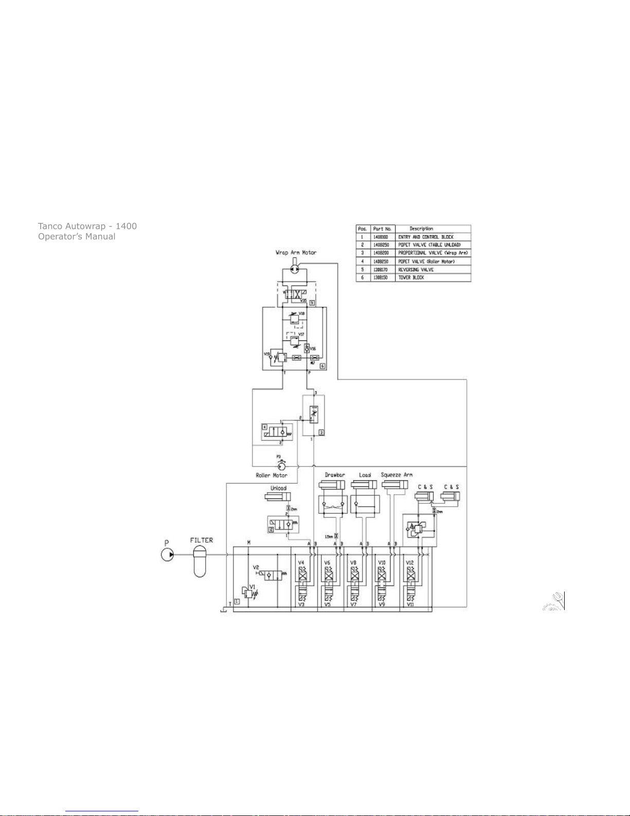
1400 Hydraulic Circuit
9. Electro-Hydraulics

Tanco Autowrap - 1400
Operator’s Manual
48
9. Electro-Hydraulics

Tanco Autowrap - 1400
Operator’s Manual
49
Solenoid Generic Function Cable Number AMP Pin 1400 Function
1 OP6 18 24 C&S Open
2 OP7 15 6 C&S Close
3 OP1 14 7 Roller Speed
4 OP2 3 14 Master Valve
5 OP4 31 16 Forward Rotate
6 OP3 6 18 Arm Speed (Prop.)
7 OP13 30 10 Squeeze In
8 OP14 11 15 Drawbar Out
9 OP8 24 22 Load Arm Up
10 OP9 27 2 Squeeze Out
11 OP16 1 19 Tip O
12 OP15 5 12 Tip Return
13 OP11 16 11 Reversing
14 OP10 26 3 Drawbar In
15 OP5 4 13 Load Arm Down
16 OP12 25 4 12 volts
1400 Junction Box Wiring
9. Electro-Hydraulics

Tanco Autowrap - 1400
Operator’s Manual
50
Solenoid Generic Function Cable Number AMP Pin 1400 Function
N/A IP1 12 9 Rotate Sensor
N/A IP2 2 20 Not Used
N/A IP3 20 31 Emergency Stop
N/A IP4 19 30 Not Used
N/A IP5 22 33 Squeeze Out
N/A IP6 13 8 Film Break 1
N/A IP8 29 5 Not Used
N/A IP9 28 1 Film Break 2
N/A AnIP5 8 26 Not Used
N/A AnIP6 7 25 Not Used
N/A 0v 35 35
N/A 0v 34 34
N/A 0v 33 23
N/A 0v 9 27
N/A An0v 21 32
5v Supply 23 28
1400 Junction Box Wiring (contd.)
9. Electro-Hydraulics

Tanco Autowrap - 1400
Operator’s Manual
51
Description of Hydraulics
The Control Valve (See Fig. 20) uses a ‘Master Valve system;
so to operate any function the master valve plus the service valve
for that function is powered. For troubleshooting purposes it is useful
to note on the control valve that, energizing a solenoid on top of the
valve gives pressure out the bottom port of that section on
valve and vice versa.
Open & Closed Center Hydraulics
The 1400 hydraulic system can be set up for tractors with
Open or Closed Center Hydraulics.
Open Centre Hydraulics
Most tractors have a hydraulic system that gives a continuous
output which ows through the valve on the machine and back
to tank when no function is operating (Open center).
Note:
The TANCO AUTOWRAP 1400 is set-up for open centre on leaving the factory.
Close Centre Hydraulics
Some tractors (John Deere) have a hydraulic system that require the valve on the machine to allow no ow when
no function is operating (Closed Center). The hydraulic valve can easily be congured to operate in this way.
Tower Valve
Arm Control Valve
Roller Stop Valve
Control Valve
Junction Box
Oil Filer
Fig. 20
9. Electro-Hydraulics

Tanco Autowrap - 1400
Operator’s Manual
52
Valve Functions
Valves 1 to 15 (See Fig. 21) are 12 V Electrical Solenoid Valves, their functions are as follows;
Valve 1 (Cutter Open) & Valve 2 (Cutter Close)
These valves open and close the lm cutter. To prevent the Cutter creeping open, there is a load holding
valve on top of the cutter section of the control valve. There is a 2mm speed control orice in the bottom
port of the cutter section.
1
2
10
7
15812
9
14
5
3
13
6
18
17
16
18
Fig. 21
9. Electro-Hydraulics

Tanco Autowrap - 1400
Operator’s Manual
53
Valve 3 - Roller Stop
This valve is normally closed; it is pulsed open and closed to give half speed on the table rollers when the
lm break sensor detects that one lm has broken.
Valve 4 - Master Valve
This valve is powered for every function.
Valve 5 - Arm Rotate
This valve powers the wrap arm and table rollers. Valve 6 is always operated with this valve.
Valve 6 - Wrap Arm Speed
This valve controls the speed of the wrap arm, it gets a varying PWM (Pulse Wave Modulation) signal from
the controller to vary the speed. Its’ settings are adjustable in the Technician Setup in the controller.
Valve 7 - Squeeze In
This valve powers squeeze arm in.
Valve 8 - Drawbar Out
This valve moves the drawbar out to the working position.
Valve 9 - Load Up
This valve raises the load arm.
Valve 10 - Squeeze Out
This valve opens the squeeze arm.
9. Electro-Hydraulics

Tanco Autowrap - 1400
Operator’s Manual
54
Valve 11- Tip Down
This poppet valve mounted on the tip port of the Control Valve lowers the rear roller frame for tipping o
bale.
Valve 12 - Tip Return
This valve raises rear roller frame after tipping.
Valve 13 - Reversing Valve
This vale mounted on the Tower Valve to reverse the direction of the wrap arm. It is always operated with
valves 5 and 6.
Valve 14 - Drawbar In
This moves the drawbar in to the transport position.
Valve 15- Load Arm Down
This valve lowers the load arm.
Valves 16,17,18 are on the Tower Block, their functions are as follows;
Valve 16 (VBS) Brake Valve.
This is a pilot operated (8:! Ratio) Load Holding Valve, it regulates the oil ow on the outlet side of the wrap
arm motor. It makes the arm run smoother and holds it in place when parked.
9. Electro-Hydraulics

Tanco Autowrap - 1400
Operator’s Manual
55
Valve 17 - (VMP) Cross Line Relief Valve Forward
This valve limits the max. torque of the wrapping arm. If the inlet pressure exceeds the set value, it relieves
the oil across to the outlet side of the motor. It is adjusted so that the pull force on the far end of the arm is
approximately 35 KG. If it is set too high acceleration at the beginning of wrapping will be very sharp.
Valve 18 - (VMT) Cross Line Relief Valve Reverse
This valve ensures a gradual stop for the wrap arm by limiting the pressure on the outlet side of the motor.
If the pressure exceeds the set value, it relieves the oil across to the inlet side of the motor.
Valve 19 - Main Relief Valve
The hydraulic system is equipped with a safety relief valve, which is preset to 185 bar. If this pressure is
exceeded it opens and allow the oil from the pressure port to the tank port of control valve
IMPORTANT:
Valves 16 to 19 have been carefully set in the factory. Incorrect adjustment of these may cause damage to
the machine. Always ensure that trained personnel only adjust the settings of these valves.
Pressure Test Point
There is a pressure test point on the inlet end of the Control Block.
9. Electro-Hydraulics

Tanco Autowrap - 1400
Operator’s Manual
56
Check Points Prior to Troubleshooting
There are some general check points that have to be examined rst if something is wrong with the
machine. There are three basic assumptions that have to be fullled for the machine to function properly;
1. The oil pressure from tractor should be 180 bar.
2. The return ow of oil has to be as free as possible, max. 10 bar counter pressure.
3. Enough electric power to all functions.
Oil Pressure
To check the oil pressure into the machine is high enough, a gauge may be placed in line on the feed hose
or there is a standard test point on the end of the Control Valve.
Oil Flow
The amount of oil that the tractor delivers should be minimum 20 liters/minute for satisfactory operation
of the machine, but it is recommended that it is 30 liters/minute.
Note: (Max. allowed oil amount is 60 liters/minute). Ensure that oil level in tractor’s hydraulic system is
correct and tractor’s oil lter is changed regularly.
Return Pressure
The return pressure can be too high. With high return pressure the machine’s functions will get less power.
High return pressure means also that you need more power to operate the valves.
Max. allowed pressure is 10 bar, we recommend “free return” directly to the tank.
10. Troubleshooting

Tanco Autowrap - 1400
Operator’s Manual
57
Electric Power
It is important to check that all functions receive enough electric power. If not, some, or all functions may
fail. The controller displays a voltage reading.
Battery Voltage
If the voltage falls below 10 V the valves will not be able to open.
Electrical Connection
The electric supply for the machine’s remote control and electro-hydraulic components must come directly
from the tractors’ 12 volt battery.
The electric wires from the battery must have an area measurement of min. 2,5 mm2. Connection to other
contacts on the tractor can cause risk of malfunction and is not recommended.
Note:
Brown leader goes to the Battery’s Positive Pole
Blue leader goes to the Battery’s Negative Pole
- Check that the connection between battery cable and control is ok.
- Check that the connection between controller unit and machine is ok.
- Check that fuse on the battery Cable is ok.
10. Troubleshooting

Tanco Autowrap - 1400
Operator’s Manual
58
Procedure of Troubleshooting
If the machine fails to operate correctly it must be determined if the problem is Hydraulic, Mechanical or
Electrical.
Solenoid Valves
When checking if the Solenoid valves are receiving electric power, you do this in the following way:
1. Unscrew the nut that holds the solenoid.
2. The solenoid is easy to move without electric power.
3. Push the current function on the remote control. If the solenoid gets power, it will be dicult to move,
it “sticks”. This is the best and easiest way to check if the solenoid valve is receiving electric power. Another
way is to hold a screwdriver up to the magnet. If it “sticks”, the solenoid is receiving electric power.
The power supply to the valve can also be measured with a voltmeter, but then the contact must be
connected to the solenoid, so it is using power. To have reliable functions, the voltage should not be lower
than 11,5 volts, even if the solenoid valve usually works with a little lower voltage.
If the electric supply is in order and one of the functions fails, the reason can be dirt that tightens or
prevents the sliding shaft (spool) from moving.
Try to manoeuvre the function manually, by pressing the point of a screwdriver into the end of the valve
housing. At the same time the corresponding switch on the control unit has to be operated to get electric
power to the master valve. If the function is working again after this, the dirt may have been pushed out in
the oil system and the machine can be operated normally again.
Take care so that the machines moving parts, do not cause damage to persons or objects.
10. Troubleshooting

Tanco Autowrap - 1400
Operator’s Manual
59
The Machine Does not Function
- Even if the gauge shows enough pressure and there is no reaction in the machine. The reason could be
that one, (or both), of the quick-couplers does not open for the oil, in this situation you should change the
quick-couplers.
- The counter pressure may be too high.
Max. allowed counter pressure is 10 bar.
Make sure that the open / closed valve is correctly positioned.
Note: Disturbances of this type, a, b or c, are most likely in the rst days that the machine is in use.
The Cutter will not Hold the Film
Is the cutter closing fully, if not increase the Cutter Close Duration 2.
If the cutter is creeping open, there may be dirt in the load holding, open and close the cutter a number
of times to try to clear this. If the problem develops over time then it may be due to seal wear in the cutter
arms.
The Wrapping Arm will not Rotate
- Check error messages on the controller,’ SQUEEZE OUT’, squeeze arm must be in the fully out position for
wrapping to start. ‘SAFETY’ if the safety arm has tripped.
- Check by hand if wrapping when parked that the wrap arm is held rmly in place; if it can be easily
moved, check chain drive, drive keys and drive motor.
10. Troubleshooting

Tanco Autowrap - 1400
Operator’s Manual
60
- Check if the arm is attempting to drive but is under pressure, unscrew adjustment on Valve 16 - Brake
Valve on Tower Block. If this does not solve problem return valve to original position.
-Check if the hydraulics are under pressure and the arm is not moving then there may be a problem with
the electrical supply to the control valve, this is best dealt with by an experienced technician.
The Hand Controller will not Operate the Lift Arm
In the Operator Setup, the Remote Type (Menu no.4.41) may be set to RF, if so, change to IR.
Please contact your dealer if you are in any doubt regarding the above.
10. Troubleshooting

Tanco Autowrap - 1400
Operator’s Manual
61
11. Maintenance
Periodic Maintenance
Bearings
All ball-bearings are packed with grease, and do not need any more maintenance.
Pre-Stretchers
If the machine is in daily use, the Gears under the plastic cover on the dispenser should be greased when
needed.
Cutters / Film Holders
The cutter / lm holder is pre-adjusted from the factory and does not need further adjustments. When
replacing spare parts, it is necessary to adjust it. The springs for the U-shaped slot shall be adjusted so that
they are almost completely squeezed together when the cutter-arm is all down.
Cleaning
The machine should be cleaned and oiled regularly and at the end of the wrapping season.
When using high pressure washing apparatus, care must be taken with the electrical installation.
Also make sure that water is not sprayed directly into the bearings, etc. Keep the control box protected
from rain and water. If necessary use compressed air to dry electrical components.
Hydraulic Cylinders
Make sure that all hydraulic cylinders are closed when storing the machine.
Quick Couplers
Ensure that the quick couplers are kept clean and apply the dust caps after use.

Tanco Autowrap - 1400
Operator’s Manual
62
Storage
The machine should be parked on a dry place during the closed season.
Oil Filter
The oil lter must be changed once a year.
Lubrication (See Fig. 22)
The table below outlines the recommended lubrication requirements for components on the 1400;
* Chain & Sprockets
Note: We recommend that you change the oil in the Tower & Table motors every 500hrs.
11. Maintenance
No. Component Type Intervals
1 Drawbar Ram Grease 50hrs
2 Table Up Ram Grease 10hrs
3 Table Tip Ram Grease 10hrs
4 Squeeze Arm Grease 10hrs
5 Cut & Tie Ram Grease 10hrs
6 Wrap Arm Drive* Oil 50hrs
7 Table Roller Drive* Oil 50hrs
8 Dispenser Gears Oil 50hrs

Tanco Autowrap - 1400
Operator’s Manual
63
1. Drawbar Ram
2. Table Up Ram
3. Table Tip Ram
4. Squeeze Arm Ram
5. Cut & Tie Ram
6. Wrap Arm Drive
7. Table Roller Drive
8. Dispenser Gears
Fig. 22
11. Maintenance

Tanco Autowrap - 1400
Operator’s Manual
64
GUARANTEE
Subject to hereunder provided, the sellers undertake to correct either by repair or at their election by
replacement any defect of material or workmanship which occurs in any of its goods within twelve months
after delivery of such goods to rst user, with the exception of contractors or commercial users when
warranty period is six months.
In respect of Autowraps the warranty period is for 12 months or 8000 bales, whichever occurs rst.
The term goods when used in this document means the article or articles described in invoices as sold by
the sellers but dose not include equipment or proprietary parts or accessories not manufactured by the
sellers. The sellers, however, undertake to pass on so far as they legally can to the rst user the benet of
any warranty given to the sellers by the suppliers of such equipment, parts or accessories.
This understanding shall not apply to:(a) Any goods that have been sold by the rst user.
(b) Any goods which have been injured by unfair wear and tear, neglect or improper use.
(c) Any goods the identication marks of which have been altered or removed.
(d) Any goods that have not received the basic normal maintenance such as tightening of bolts, nuts,
tines, hose connections and ttings and normal lubrication with the recommended lubricant.
(e) The use of any product on tractors exceeding the recommended horsepower.
(f) Any goods that have been altered or repaired other that on instruction or with the written
approval of the seller or to which any part not manufactured or having written approval by the sellers have
been xed.
(g) Any second-hand goods or parts thereof.
12. Guarantee

Tanco Autowrap - 1400
Operator’s Manual
65
Any allegedly defective part or parts returned to the seller must be sent carriage paid. No claim for repair
or replacement will be entertained unless upon discovery of the alleged defect written notication is sent
to the Sellers giving, at the same time, the name of the Buyer from whom the goods were purchased and
the date of purchase, together with the full details of the alleged defect and the circumstances involved,
also the serial number of the machine etc.
The sellers shall be under no liability to their Buyers and rst or subsequent users of their goods or to any
other person or persons for loss or damage howsoever arising in respect of either personal injuries or for
arising out of, or in any other way connected with or arising from the manufactures sale, handling, repair,
maintenance, replacement or use of its goods or the failure or malfunction of any of its goods.
Representation and/or warranties made by any persons (including Buyers and employees and other representatives of the Seller) which are inconsistent or conicting with these conditions are not binding upon
the sellers unless given in writing and signed by a director of sales.
CLAIMS
If you wish to make a claim under the guarantee:
1: Immediately, stop using the machine.
2: Consult with your Tanco dealer (supplier). He/She can download a warranty claim form on-line. This
should be lled out and e-mailed to distributor and forwarded to relevant contact person in Tanco. Please
ensure all relevant information is included on this form
3: Consult with your Tanco dealer (supplier) and have them forward your claim and the damaged item to
Tanco.
12. Guarantee

Tanco Autowrap - 1400
Operator’s Manual
66
EC DECLARATION OF CONFORMITY
ACCORDING TO DIRECTIVES 8 9/392/336 /EEC AS AMENDED
Manufacturer:
Tanco Autowrap Ltd
Bagenalstown
Co. Carlow
IRELAND
CERTIFIES THAT THE FOLLOWING PRODUCT:
TANCO AUTOWRAP
MODEL: 1400EH
SERIAL NO:
To which this declaration relates, corresponds to the essential requirements of the Directive 89/392/336/
EEC as amended.
To conform to these essential health and safety requirements, the provisions of the following harmonized
standards were particularly considered:
EN 292-1,2, EN 294, EN 1152, prEN 703, prEN 811, prENl553, prEN 982.
DATE 14.02.09
Signed:
Con Hourihane, Technical Manager
13. Declaration of Conformity

Tanco Autowrap - 1400
Spare Parts Manual
1
1400 Spare Parts List
We recommend that when you require spare parts you use only original parts.
When ordering spare parts please follow the following steps;
1. Identify the part you require using the detailed drawings.
2. Once you have identied the part you require reference the item numbder relating to the part on the
item list where you will nd the part number and description of the part you require. You will be require
to give the complete part no and decription when ordering your part(s).
3. When ordering you must give the Serial Number and Model Number of the machine.
4. All orders must go through your local Tanco Dealer, and must be either faxed or e-mailed to Tanco
Autowrap.

Tanco Autowrap - 1400
Spare Parts Manual
2
Chapter Contents Page
1 Chassis Assembly 3
2 Cut & Tie Assembly 17
3 Table Assembly 25
4 Tower Assembly 43
5 Dispenser Assembly 57
6 Controller Mounting Assembly 63
Table of Contents
- Section 2: Spare Parts Manual -

Tanco Autowrap - 1400
Spare Parts Manual
3
1. Chassis Assembly
1.1 Control Valve Mouting
1.2 Wheels & Mudguards
1.3 Chassis Bale Guide
1.4 Drawbar
1.5 Swivel Hitch
1.6 Cut & Tie / Ram Mountings
Tanco Autowrap - 1400
Spare Parts Manual
4
1
2
2A
3
4
5
6
3A
3B
3C
4A
4B
4A
4B
4C
4D
4E
4F
5A
5A
5C
5B
7A
7B
7C
6A
6B
6C
7
8
8A
8B
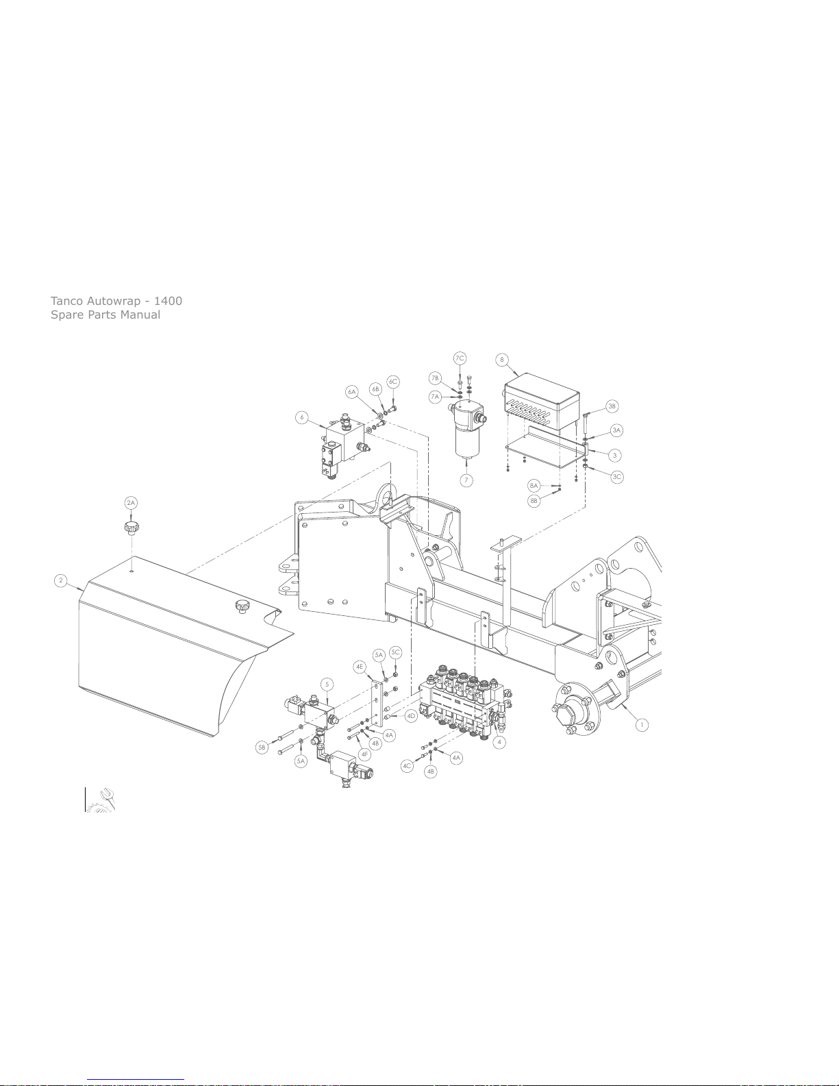
1. Chassis Assembly
1.1 Control Valve Mouting
1.2 Wheels & Mudguards
1.3 Chassis Bale Guide
1.4 Drawbar
1.5 Swivel Hitch
1.6 Cut & Tie / Ram Mountings

Tanco Autowrap - 1400
Spare Parts Manual
5
Item No. Part No. Description Qty
1 1401100 Chassis 1
2 1401060 Valve Cover 1
2A 34251456 Handwheel (50 x 10) 2
3 1401050 Junction Box Mounting Bracket 1
3A Z10-02-08 8mm Flat Washer 2
3B Z26-048B M8 x 65mm Hex Bolt 1
3C Z23-08 8mm Locknut 1
4 1408100 Control Valve 1
4A Z10-02-06 6mm Flat Washer 4
4B Z12-02-06 6mm Spring Washer 4
4C Z26-020S M6 x 20mm Hex Set 2
4D 1403044 Valve Spacer 2
4E 1401066 Valve Mounting Bracket 1
4F Z26-026B M6 x 50mm Hex Bolt 2
5 1408210 Proportional Valve 1
5A Z10-02-08 8mm Flat Washer 4
5B Z26-048B M8 x 65mm Hex Bolt 2
5C Z23-08 8mm Locknut 2
Item No. Part No. Description Qty
6 1308180 Tower Block 1
6A Z10-02-10 10mm Flat Washer 2
6B Z12-02-10 10mm Spring Washer 2
6C Z26-0611S M10 x 25mm Hex Set 2
7 1308070 Oil Pressure Filter 1
7A Z10-02-08 8mm Flat Washer 2
7B Z12-02-08 8mm Spring Washer 2
7C Z26-039S M8 x 20mm Hex Set 2
8 1409100 RDS Control Kit (Junction Box) 1
8A Z10-02-04 4mm Flat Washer 2
8B Z23-04 4mm Locknut 2
1.1 Control Valve Mounting

Tanco Autowrap - 1400
Spare Parts Manual
6
1
2
3
4
5
4A
4B
4C
4D
2B
6
6B
6C
6A
3A
3C
3B
3A
2A
1. Chassis Assembly
1.1 Control Valve Mouting
1.2 Wheels & Mudguards
1.3 Chassis Bale Guide
1.4 Drawbar
1.5 Swivel Hitch
1.6 Cut & Tie / Ram Mountings

Tanco Autowrap - 1400
Spare Parts Manual
7
Item No Part No Description Qty
1 1401100 Chassis 1
2 1402100 Mud Guard Mounting Bracket (Right) 1
2A Z10-02-12 12mm Flat Washer 4
2B Z26-084S M12 x 40mm Hex Set 2
2C Z23-12 12mm Locknut 2
3 1401250 Plastic Mudguard 1
3A Z10-02-08 8mm Flat Washer 8
3B Z23-08 8mm Locknut 4
4 Z04-032 Stub Axle 1
4A M22AWNA M16 Wheel Nut 5
4B Z10-02-12 12mm Flat Washer 2
4C Z26-0901B M12 x 80mm Hex Bolt 1
4D Z23-12 12mm Locknut 1
5 Z04-04-1070 5 Stud Road Wheel 1
Item No Part No Description Qty
6 Z05-32 Lighting Set 1
6A Z04-621 100 x 45 Reector 1
6B Z10-02-05 5mm Flat Washer 2
6C Z23-05 5mm Locknut 2
1.2 Wheels & Mudguards

Tanco Autowrap - 1400
Spare Parts Manual
8
1
2
2A
2A
2B
2C
1. Chassis Assembly
1.1 Control Valve Mouting
1.2 Wheels & Mudguards
1.3 Chassis Bale Guide
1.4 Drawbar
1.5 Swivel Hitch
1.6 Cut & Tie / Ram Mountings

Tanco Autowrap - 1400
Spare Parts Manual
9
1.3 Chassis Bale Guide
Item No Part No Description Qty
1 1401100 Chassis 1
2 1401070 Bale Guide 1
2A Z10-02-10 12mm Flat Washer 8
2B Z26-084S M12 x 40mm Hex Set 4
2C Z23-12 12mm Hex Set 4

Tanco Autowrap - 1400
Spare Parts Manual
10
1
2
2B
3
3A
3B
3B
3C
3D
4
4A
4B
5
5A
5B
5C
5D
6
6A
6A
6B
6C
6D
7
7A
7C
7B
7D
7E
7
7A
7B
1. Chassis Assembly
1.1 Control Valve Mouting
1.2 Wheels & Mudguards
1.3 Chassis Bale Guide
1.4 Drawbar
1.5 Swivel Hitch
1.6 Cut & Tie / Ram Mountings

Tanco Autowrap - 1400
Spare Parts Manual
11
1.4 Drawbar
Item No Part No Description Qty
1 1401100 Chassis 1
2 1401500 Drawbar 1
2A 34060800 M8 x 1.25 Grease Nipple 1
2B 1404056 DX Bush (40mm Bore x 50mm) 2
3 1408015 Film Roll Holder 3
3A Z32-085 External Tube Cap 6
3B Z10-02-12 M12 Flat Washer 12
3C Z26-038B M12 x 35mm Hex Bolt 6
3D Z23-12 M12 Locknut 6
4 1401075 Drawbar Leg 1
4A Z03-04-74 Link Pin 2
4B Z03-22-03 1/4" Linch Pin 2
5 1401600 Hitch Eye 1
5A 1403005 Bolt Plate 1
5B Z10-02-20 M20 Flat Washer 2
5C Z12-02-20 M20 Spring Washer 2
5D Z26-165B M20 x 70mmHex Bolt 2
Item No Part No Description Qty
6 1408166 Drawbar Ram 1
6A 1401716 Ram Mounting Pin 2
6B Z10-02-10 M10 Flat Washer 4
6C Z26-063S M10 x 35mm Hex Set 2
6D Z23-10 M10 Locknut 2
7 34260117M 22mm Pipe Clamp (Pair) 1
7A 34260117 Pipe Clamp Top Plate 1
7B Z26-042B M8 x 45mm Hex Bolt 1
8 1401713 Drawbar Pivot Pin 1
8A Z26-063S M10 x 35mm Hex Set 1
8B Z10-02-10 M10 Flat Washer 2
8C Z23-10 M10 Locknut 1
8D 1403033 Countersunk Pin Cap 1
8E Z13-5-10X25 M10 x 25mm CSK Allen Set 1

Tanco Autowrap - 1400
Spare Parts Manual
12
1. Chassis Assembly
1.1 Control Valve Mouting
1.2 Wheels & Mudguards
1.3 Chassis Bale Guide
1.4 Drawbar
1.5 Swivel Hitch
1.6 Cut & Tie / Ram Mountings
1
2
3
3A
3B
4
4A
4B
4C

Tanco Autowrap - 1400
Spare Parts Manual
13
1.5 Swivel Hitch
Item No Part No Description Qty
1 1401500 Drawbar 1
2 1401100 Swivel Hitch 1
2A Z03-22-06 7/16" Dia Linch Pin 2
3 34105716 3pt Pont Linkage Pin 2
3A Z12-02-25 25mm Flat Washer 2
3B 1401109 3pt Pont Linkage Nut 2
4 1401074 Swivel Collar 1
4A Z10-02-10 M10 Flat Washer 2

Tanco Autowrap - 1400
Spare Parts Manual
14
2
2A
2B
1
2A
2C
3
3A
3C
3A
3B
4
4A
4B
4C
4D
1A
1B
1C
5
5A
5B
5C
5D
2
1. Chassis Assembly
1.1 Control Valve Mouting
1.2 Wheels & Mudguards
1.3 Chassis Bale Guide
1.4 Drawbar
1.5 Swivel Hitch
1.6 Cut & Tie / Ram Mountings

Tanco Autowrap - 1400
Spare Parts Manual
15
Item No Part No Description Qty
1 1401100 Chassis 1
1A Z01-24-2618 18mm Pipe Clamp (Pair) 7
1B Z01-24-27 Pipe Clamp Top Plate 7
1C Z26-042B M8 x 35mm Hex Bolt 7
2 1406100 Professional Cut & Tie 2
2A Z11-02-101 8mm Mudwasher 8
2B Z26-063S M10x 35mm Hex Set 4
2C Z23-10 10mm Locknut 4
3 1401086 Cut & Tie Mounting Bracket 2
3A Z10-02-12 12mm Flat Washer 8
3B Z26-085S M12 x 45mm Hex Set 4
3C Z23-12 12mm Locknut 4
4 1408169 Unloading Damper Ram 1
4A 1401720 Ram Mounting Pin 1
4B Z10-02-10 10mm Flat Washer 1
4C Z26-063S M10 x 35mm Hex Set 1
4D Z23-08 10mm Locknut 1
Item No Part No Description Qty
5 1408167 Table Loading Ram 1
5A 1401710 Ram Mounting Pin 1
5B Z10-02-10 10mm Flat Washer 1
5C Z26-063S M10 x 35mm Hex Set 1
5D Z23-08 10mm Locknut 1
1.6 Cut & Tie / Ram Mountings

Tanco Autowrap - 1400
Spare Parts Manual
16

Tanco Autowrap - 1400
Spare Parts Manual
17
2. Professional Cut & Tie Assembly
2.1 Cut & Tie Base Asseembly
2.2 Cut & Tie Pressure Arm Assembly
2.3 Cut & Tie Top Arm Assembly

Tanco Autowrap - 1400
Spare Parts Manual
18
2. Professional Cut & Tie Assembly
2.1 Cut & Tie Base Assembly
2.2 Cut & Tie Pressure Arm Assembly
2.3 Cut & Tie Top Arm Assembly
1
1A
1A
1C
1D
1E
1B
2
2A
2B
2C
2C
3
3A
3B
3C
3D
3E
3F

Tanco Autowrap - 1400
Spare Parts Manual
19
Item No Part No Description Qty
1 1406060 Cut & Tie Base 1
1A 1406080 Cut & Tie Pin (Long) 2
1B 1406035 Ram Spacer 1
1C Z11-02-081 8mm Mud Washer 2
1D Z12-02-08 8mm Spring Washer 2
1E Z26-039S M8 x 20mm Hex Set 2
2 1308151 Cut & Tie Ram 1
2A 34060800 M8 x 1.25 Grease Nipple 2
2B 34105631 Ram Mounting Pin 1
2C Z28-525 M25 External Circlip 2
3 34920525 Cut & Tie Casting 1
3A Z11-02-081 8mm Mud Washer 2
3B Z26-045S M8 x 50mm Hex Set 1
3C Z18-08 8mm Plain Hex Nut 1
3D Z11-02-081 8mm Mud Washer 2
3E Z26-041S M8 x 30mm Hex Set 2
3F Z23-08 8mm Hex Nut 2
2.1 Cut & Tie Base Assembly

Tanco Autowrap - 1400
Spare Parts Manual
20
2. Professional Cut & Tie Assembly
2.1 Cut & Tie Base Assembly
2.2 Cut & Tie Pressure Arm Assembly
2.3 Cut & Tie Top Arm Assembly
1
2
2A
1B
2C
1D
1A
1C
2B
1E
1F
1G

Tanco Autowrap - 1400
Spare Parts Manual
21
2.2 Cut & Tie Pressure Arm Assembly
Item No Part No Description Qty
1 1406112 Cut & Tie Lift Arm 1
1A 34060800 M8 x 1.25 Grease Nipple 2
1B 1406074 Cut & Tie Balde 1
1C Z03-25-05 Pop Rivet 5
1D 1406075 Film Gathering Bar 1
1E Z10-02-06 6mm Flat Washer 2
1F Z12-02-06 6mm Spring Washer 2
1G Z26-020S M6 x 20mm Hex Set 2
2 1406101 Pressure Plate 1
2A 1406706 Rubber Strip 1
2B Z03-25-05 Pop Rivet 5
2C 1406078 Pressure Spring 1
2D Z23-10 10mm Locknut 2

Tanco Autowrap - 1400
Spare Parts Manual
22
2. Professional Cut & Tie Assembly
2.1 Cut & Tie Base Assembly
2.2 Cut & Tie Pressure Arm Assembly
2.3 Cut & Tie Top Arm Assembly
1
2
3
1A
1B
1C
1D
1E
1F
3A
4
4A
4B
4C
1G
1H
1I
2A
2B
2C
2D
2A

Tanco Autowrap - 1400
Spare Parts Manual
23
2.2 Cut & Tie Top Arm Assembly
Item No Part No Description Qty
1 1406113 Pull Down Arm 1
1A 1406077 Knurled Roller 1
1B 1406085 Cut & Tie Pin (Short) 1
1C 1406080 Cut & Tie Pin (Long) 1
1D Z11-02-081 8mm Mud Washer 2
1E Z12-02-08 8mm Spring Washer 2
1F Z26-039S M8 x 20mm Hex Set 2
1G Z10-02-10 10mm Flat Washer 1
1H Z12-02-10 10mm Spring Washer 1
1I Z26-0611S M10 x 25mm Hex Set 1
2 1406065 Top Arm 1
2A Z10-02-08 8mm Flat Washer 2
2B Z12-02-08 8mm Spring Washer 2
2C Z18-08 8mm Plain Hex Nut 1
2D Z26-041S M8 x 30mm Hex Set 1
3 1406102 Connecting Arm 1
3A 34060800 M8 x 1.25 Grease Nipple 2
Item No Part No Description Qty
4 1406068 Film Roller 1
4A Z18-08 8mm Plain Hex Nut 2
4B Z12-02-08 8mm Spring Washer 2
4C Z13-5-08X35 M8 x 35mm CSK AH Set 2

Tanco Autowrap - 1400
Spare Parts Manual
24

Tanco Autowrap - 1400
Spare Parts Manual
25
3. Table Assermbly
3.1 Chain Drive
3.2 Roller / Bearing Covers
3.3 Front Belt Guides
3.4 Rear Belt Guides
3.5 Bale Rollers
3.6 Table Pins (1)
3.7 Table Pins (2)
3.8 Loading Arm

Tanco Autowrap - 1400
Spare Parts Manual
26
1
2
4
4A
4C
4B
2D
2F
2E
5
2A
2B
2G
2H
1A
1B
1C
6
2C
6A
3
3A
3B
6B
6C
3. Table Assermbly
3.1 Chain Drive
3.2 Roller / Bearing Covers
3.3 Front Belt Guides
3.4 Rear Belt Guides
3.5 Bale Rollers
3.6 Table Pins (1)
3.7 Table Pins (2)
3.8 Loading Arm

Tanco Autowrap - 1400
Spare Parts Manual
27
3.1 Chain Drive
Item No Part No Description
Qty1 1403300 Table - Load Frame 1
1A Z01-24-2618 18mm Pipe
Clamp (Pair) 1
1B Z01-24-27 Pipe Clamp Top Plate 1
1C Z26-042B M8 x 35mm Hex Bolt 1
2 1508800 Roller
Drive Motor (BRS400 NC25) 1
2A Z10-02-12 M12
Flat Washer 2
2B Z26-084S M12 x
Item No Part No Description Qty
1 1403300 Table - Load Frame 1
1A Z01-24-2618 18mm Pipe Clamp (Pair) 1
1B Z01-24-27 Pipe Clamp Top Plate 1
1C Z26-042B M8 x 35mm Hex Bolt 1
2 1508800 Roller Drive Motor (BRS400 NC25) 1
2A Z10-02-12 M12 Flat Washer 2
2B Z26-084S M12 x 40mm Hex Set 1
2C Z26-088S M12 x 40mm Hex Set 1
2D 1502098 11 Tooth 3/4” Sprocket 1
2E 34270111 8mm x 7mm x 30mm Key Steel 1
2F Z28-008 M8 x 10mm Grub Screw 1
2G Z12-02-12 M12 Spring Washer 2
2H Z23-12 M12 Locknut 2
3 1403056 Chain Tensioning Bracket 1
3A Z26-067S M10 x 60mm Hex Set 1
3B Z18-10 10mm Plain Hex Nut 2
Item No Part No Description Qty
4 1403100 Drive Roller 1
4A 1403041 29 Tooth 3/4" Sprocket 1
4B 1403045 10mm x 8mm x 40mm Key Steel 1
4C Z28-008 M8 x 10mm Grub Screw 2
5 34810834 3/4" Chain (33 3/4" Long) 1
6 1403350 Sprocket & Chain Guard 1
6A Z11-02-081 8mm Mud Washer 2
6B Z12-02-08 8mm Spring Washer 2
6C Z26-041S M8 x 30mm Hex Set 2

Tanco Autowrap - 1400
Spare Parts Manual
28
1
2
3
4
5
1A
1B
1A
1C
4A
4B
4C
5A
4A
4B
4C
3. Table Assermbly
3.1 Chain Drive
3.2 Roller / Bearing Covers
3.3 Front Belt Guides
3.4 Rear Belt Guides
3.5 Bale Rollers
3.6 Table Pins (1)
3.7 Table Pins (2)
3.8 Loading Arm

Tanco Autowrap - 1400
Spare Parts Manual
29
Item No Part No Description Qty
1 1403450 Table - Unload Frame 1
1A Z10-02-10 M10 Flat Washer 4
1B Z26-065S M10 x 45mm Hex Set 2
1C Z23-10 M10 Locknut 2
2 1403108 Idler Roller 1
3 Z05-02-ILS 3265 X 200 (VEB) Strip Belt 4
4 1403125 Roller / Bearing Guard 1
4A Z11-02-081 M8 Mudwasher 2
4B M12-02-08 M8 Spring Washer 2
4C Z26-039S M8 X 20mm Hex Set 2
5 1403013 Bearing Cover Mounting Bracket 1
5A 1804101 Bearing - SA207 (w/ Cam Lock & Housing) 1
3.2 Roller / Bearing Covers

Tanco Autowrap - 1400
Spare Parts Manual
30
3. Table Assermbly
3.1 Chain Drive
3.2 Roller / Bearing Covers
3.3 Front Belt Guides
3.4 Rear Belt Guides
3.5 Bale Rollers
3.6 Table Pins (1)
3.7 Table Pins (2)
3.8 Loading Arm
1
2
3
4
3B
3A
3A
3C
5
5A
5A
5D
5C
5B

Tanco Autowrap - 1400
Spare Parts Manual
31
3.3 Front Belt Guides
Item No Part No Description Qty
1 1403300 Table - Load Frame 1
2 1403100 Drive Roller 1
3 1403561 Belt Guide Top Prole 1
3A Z10-02-10 M10 Flat Washer 4
3B Z26-063S M10 x 35mm Hex Set 2
3C Z23-10 M10 Locknut 2
4 1403562 Belt Guide Bottom Prole 2
5 Z26-068B M10 x 70mm Hex Bolt 8
5A Z10-02-10 M10 Flat Washer 16
5B 1403565 Belt Guide Inner Roller (Short) 8
5C 1403566 Belt Guide Outer Roller (Short) 8
5D Z23-10 M10 Locknut 8

Tanco Autowrap - 1400
Spare Parts Manual
32
3. Table Assermbly
3.1 Chain Drive
3.2 Roller / Bearing Covers
3.3 Front Belt Guides
3.4 Rear Belt Guides
3.5 Bale Rollers
3.6 Table Pins (1)
3.7 Table Pins (2)
3.8 Loading Arm
1
2
3
4
3B
3A
3C
3B
3A
3C
5
5A
5C
5B
5A
5D
3A
3A

Tanco Autowrap - 1400
Spare Parts Manual
33
3.4 Rear Belt Guides
Item No Part No Description Qty
1 1403450 Table - Unload Frame 1
2 1403108 Idler Roller 1
3 1403561 Belt Guide Top Prole 1
3A Z10-02-10 M10 Flat Washer 4
3B Z26-063S M10 x 35mm Hex Set 2
3C Z23-10 M10 Locknut 2
4 1403562 Belt Guide Bottom Prole 2
5 Z26-072B M10 x 110mm Hex Bolt 8
5A Z10-02-10 M10 Flat Washer 16
5B 1403563 Belt Guide Inner Roller (Long) 8
5C 1403564 Belt Guide Outer Roller (Long) 8
5D Z23-10 M10 Locknut 8
 Loading...