

Page 1

TSW-210
POWER SWEEPER ATTACHMENT
OWNER’S MANUAL
FOR USE ON TANAKA STRAIGHT SHAFT GRASS TRIMMERS
Page 2
OWNER’S MANUAL
TABLE OF CONTENTS
Foreword . . . . . . . . . . . . . . . . . . . . . . .2 Assembly Instructions . . . . . . . . . . . . .4-5
Safety Symbols . . . . . . . . . . . . . . . . . . .2 Operating Instructions . . . . . . . . . . . . . .6
Product Description . . . . . . . . . . . . . . . .2 Maintenance . . . . . . . . . . . . . . . . . . . . .7
Safety Instructions . . . . . . . . . . . . . . .3-4
FOREWORD
This Owner’s/Operator’s Manual is designed to familiarize the operator with the various features and
component parts of the equipment and to assist with the assembly, operation and maintenance of the
product.
It is essential that any operator of this product reads and understands the contents of this manual
before using the product.
Important safety instructions will be identified by the following safety symbol:
Failure to comply with the instructions in this manual may result in serious injury or death.
For additional assistance, contact any local authorized Tanaka dealer or contact Tanaka USA at 1-888-482-
6252.
MANUAL SAFETY SYMBOLS
Throughout this manual and on the product itself, you will find safety alerts and helpful information
messages preceded by symbols or key words. The following is an explanation of those symbols and key
words and what they mean to you.
This symbol accompanied by the words WARNING and DANGER calls attention to an act or
condition that can lead to serious personal injury to the operator or bystanders.
11
1
11
22
2
22
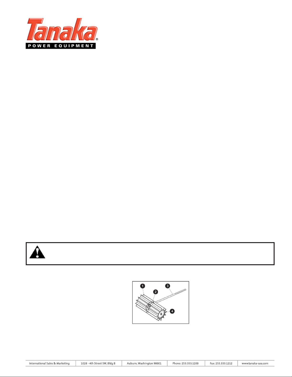
PRODUCT DESCRIPTION
1. Sweeper Belt
2. Gearcase
3. Outer Tube (Shown for reference only)
4. Sweeper Drum
- 2 -
44
4
44
Page 3

SAFETY INSTRUCTIONS
PRODUCT SAFETY
1. Read and understand this Owner’s/Operator’s Manual
before using this product. Be thoroughly familiar with the
proper use of this equipment.
2. Make sure the product is correctly assembled and
installed prior to use.
3. Never allow children to operate the product. Never
allow adults to operate the unit without first reading the
Owner’s/Operator’s Manual.
4. Never operate this product without proper guards or
other protective safety devices in place.
OWNER’S MANUAL
5. Before each use, inspect the product. Replace damaged parts. Make sure all fasteners are in place and
tightened securely.
6. If running problems or excessive vibration occur, stop immediately and inspect the unit for the cause. If
the cause cannot be determined, or is beyond your ability to correct, return the product to your servicing
dealer for repair.
7. Do not use this product for any job except that for which it is intended.
OPERATOR SAFETY
1. Never operate this product when you are tired, ill, or while under the influence of alcohol, drugs or
medication.
2. Always wear eye protection that complies with ANSI (American National Standards Institute) Z87-1.
3. Wear hearing protection.
4. Always wear heavy, long pants, boots and gloves. Do not wear loose clothing, jewelry, short pants,
sandals or go barefoot. Secure hair so it is above shoulder length.
5. To reduce risk of injury associated with inhalation of dust wear a face filter mask in dusty conditions.
6. Always operate with both hands firmly gripping the product.
7. Keep clear of the rotating belts and paddles at all times.
8. Never raise a moving attachment above waist level.
9. Do not put hands or feet near or under rotating parts. Keep clear at all times.
10. To reduce risk of injury associated with contact with a rotating part, stop engine before installing or
removing attachments.
- 3 -
Page 4

OWNER’S MANUAL
SAFETY INSTRUCTIONS
AWARENESS OF WORK ENVIRONMENT
1. Inspect your work area before you begin. Remove objects such as broken glass, nails, wire and rocks
which can become dangerous projectiles if thrown. Remove string, rope or similar materials which can
become entangled in the rotating drum.
2. Maintain a firm footing and balance while operating the product. Do not overreach.
3. Keep children, bystanders and animals outside a 50ft. (15m) radius surrounding the area of operation.
4. Use the product only in daylight or adequate artificial lighting.
5. Avoid prolonged operation in very hot or very cold conditions.
6. If contact is made with a hard object, stop the engine and inspect the sweepers and drums for damage.
ASSEMBLY INSTRUCTIONS
- 4 -
33
3
33
Page 5

OWNER’S MANUAL
INSTALLING THE GEARBOX SWEEPING ATTACHMENT
1. Make sure all the components are included in the box. The box should contain:
a. Gearbox (1)
b. Drum Assemblies (2)
c. Drum Axle (2)
d. Clevis Pin (2)
e. Hitch Pin (2)
f. Cotter Pin (2)
g. Shaft Protector (2)
h. Gearcase Spacer (1)
2. Slide the rubber sleeve drive shaft protector onto the drive shaft pipe housing. This sleeve will protect the
drive shaft pipe from repeated contact with the rubber paddles. The protector can be slid up the drive shaft pipe
housing during installation, but should be slid down to rest on top of the gear case before use.
3. Insert the end of the drive shaft housing into the gearcase and push it until it bottoms. The drive shaft tube
should go into the gearcase about 1 - 1.5 inches. If the drive shaft housing stops before bottoming, rotate it
until you feel the inner drive shaft splines engage the gearcase. Then push the drive shaft all of the way in.
4. All Tanaka trimmers use a locator screw to properly position the gear case, (in addition to the pinch bolt which
tightens the gear case to the shaft). Some trimmer models do not have the locator screw and hole in the correct
place for mounting the sweeper gear case. In this instance, an additional hole will need to be drilled. Insert the
shaft pipe all the way into the sweeper gear case, and mark the center of the locator bolt hole. Remove the drive
shaft pipe, and use the existing gear case hole to ensure you have the new hole properly centered (to ensure the
gear case is straight). Using a 6mm (3/8”) drill bit, drill the new locator hole in the drive shaft pipe.
5. Use a 4mm hex (Allen) wrench to tighten the gearcase positioning screw first, then the gearcase clamp screw.
6. Push one of the drum axles onto either of the two gearcase output shafts. If necessary, rotate the drum axle
until the clevis pin hole in the axle aligns with the matching hole in the gearcase output shafts.
7. Use a clevis pin and hitch pin to secure the drum axle to the shaft.
8. Slide the recessed end of a sweeper drum assembly over the installed axle, and then push the drum down the
axle until the cotter pin hole in the axle extends above the drum surface.
Important Note: The two drum assemblies are identical, but each drum must be
installed with the recessed end facing toward the gearcase.
9. Use a cotter pin to secure the drum assembly on the axle. The cotter pin is designed to fit tightly against the
outboard end of the drum, so you may need to compress the drum face slightly during installation. Spread the
ends of the cotter pin to secure.
10. Repeat steps 7 - 10 to install the remaining axle and drum assembly.
- 5 -
Page 6

OWNER’S MANUAL
OPERATING INSTRUCTIONS
BREAK-IN
The Power Sweeper operates best when the fins quickly slide or skim the surface being swept. New or
replacement sweeper belts will tend to grip or drag on hard surfaces, and should be fully broken in prior to
actual operation. Break in is accomplished by operating the product at full throttle for 3 - 5 minutes in
loose gravel or similar abrasive material.
Important Note: It is tiring and unnecessary to lift or hold the fins from the work surface
during operation.
Warning: Burn Danger. The gearcase will become very hot during normal operation.
OPERATING TECHNIQUES
Operate the product at or near full throttle with the sweeper fins
resting on the work surface.
CLEARING NARROW AREAS
When sweeping narrow areas such as sidewalks, the Power Sweeper can
be used to throw material
directly ahead of the operator.
CLEARING WIDER AREAS
Clearing wider areas may require sweeping at an angle to create
windrows to one side of the path being cleared. Windrows of lighter
materials can be combined into one main row or pile for eventual pick
up, while heavy or bulky material may need to be collected row by row.
CLEARING CORNERS
To pull debris from corners, reverse the sweeper drum rotation by
turning the powerhead over (throttle facing up).
Warning: Use lower throttle settings when reversing the
Sweeper to sweep corners as debris will be thrown
toward the operator in this position. Also be aware that
thrown debris may affect footing.
-6 -
Page 7

OWNER’S MANUAL
MAINTENANCE - 300 HOURS
GEARCASE LUBRICATION
The gearcase should be filled with 60cc (2.0 fl.oz.) of Mobil SHC634 Synthetic Gear Oil. A maximum of 75 80cc can be used, but never exceed 80cc. Operation with excessive oil level will result in high operating
temperatures. Do not overfill.
REPLACING THE GEARCASE OIL
Warning: Burn Danger. The gearcase will be extremely hot after use.
1. Disconnect the spark plug wire at the engine.
2. Remove the left hand drum and axle assembly (as viewed from the operating position). Wipe the
sideplate clean and remove four screws (it is not necessary to remove the gearcase from the outer tube).
3. Turn gearcase side plate to break the seal and lift the plate from the
gearcase.
Note: It may be necessary to use a heat gun to softenthe sealer
material.
4. Turn the gearcase to the left hand side and allow all used gearcase
oil to drain into a small container.
5. Place the gearcase on the right hand side and support so the outer
tube is parallel to the ground. Refill the gearcase with 60cc (2.0 fl.oz.)
of Mobil SHC634 Synthetic Gear Oil to the bottom of the chamfer on
the output gear. The correct oil depth is 5/8 inch (15.5mm). Do not
over fill.
6. Inspect the sideplate for damage and clean off all remaining liquid
gasket material with brake cleaner or acetone. Coat the outer sealing
flange of the sideplate with Loctite Ultragrey silicon sealant or
Threebond No. 1104 Liquid gasket.
7. Replace the cover and install the four sideplate screws. Tighten securely.
8. Reinstall the drum and axle assembly per the Assembly Instructions on page 4. Fill to this
level
- 7 -
Page 8

OWNER’S MANUAL
For more information on this product including a complete illustrated parts list,
go to www.tanaka-usa.com
 Loading...