

Page 1

Model Number:
IllustrIllustr
Illustr
IllustrIllustr
aa
ted Pted P
a
ted P
aa
ted Pted P
arar
ar
arar
ts Mants Man
ts Man
ts Mants Man
ualual
ual
ualual
THT-2100
HEDGETRIMMER
P/N 27123
Rev 002
Date 10-15-07
Nikko Tanaka Engineering U.S.A.,Ltd.• 1028 4th Street SW, Bldg B • Auburn, WA 98001 • Phone: (253) 333-1200 • Fax: (253) 333-1212
www.tanakapowerequipment.com custsvc@nikko-tanaka-usa.com
Page 2
PARTS INFORMATION
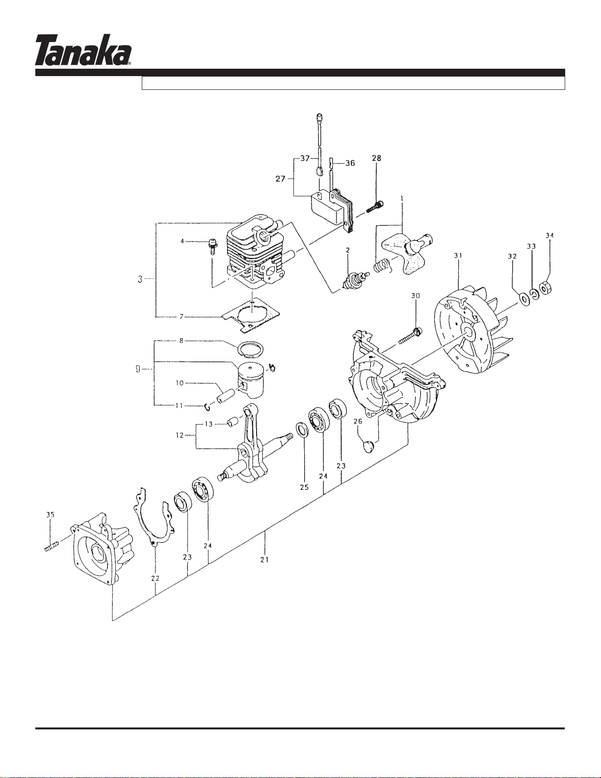
ENGINE / CYLINDER, PISTON, CRANKSHAFT • FIGURE 1
THT-2100
www.tanakapowerequipment.com
Page 1
custsvc@nikko-tanaka-usa.com
Page 3

PARTS INFORMATION
THT-2100
ENGINE / CYLINDER, PISTON, CRANKSHAFT • FIGURE 1
ITEM PART NUMBER DESCRI PTION QTY COMMENTS
1-1 1570650091 CAP,SPARK PLUG ASS'Y 1
1-2 01804075200 PLUG,SPARK 1
1-3 0010650090 SET,CYLINDER 1 Includes cylinder gasket
1-4 99416050201 SCREW,5X20/WS 2
1-7 0170650020 GASKET, CYLINDER 1
1-8 04100601210 RING,PISTON 1
1-9 0300650090 SET,PISTON 1 Includes rings, and circlips
1-10 03706500200 PIN,PISTON 1
1-11 03901620200 CIRCLIP,PISTON PIN 2
1-12 04606500801 CRANKSHAFT 1
1-13 99962081225 BEARING,NEEDLE,F-810 1
1-21 0720650090 CRANKCASE ASS'Y 1 Crankcase assy includes bearings, seals
1-22 09006500200 GASKET,CRANKCASE 1 and gasket.
1-23 99966122206 SEAL,OIL,#TC12227 2
1-24 99961600100 BEARING,BALL,#6001 2
1-25 33000200210 SHIM,12.2X19X.10 V Shims are "as needed" to obtain
1-25 33000200220 SHIM,12.2X19X.15 V correct side clearance
1-25 33000200230 SHIM,12.2X19X.20 V
1-25 33000200240 SHIM,12.2X19X.30 V
1-26 59900601200 CUSHION 1
1-27 1672153280 COIL,IGNITION 1
1-28 99416040226 SCREW,W S,4X22 2
1-30 99414050301 SCREW,5X30/S 3
1-31 1552152380 ROTOR, MAGNETO 1
1-32 99201080011 WASHER,8 1
1-33 99210080012 WASHER,S,8 1
1-34 99101080011 NUT,8 1
1-35 10002100200 BOLT,STUD,6X22 2
1-36 25006500200 TUBE,INSULATOR 1
1-37 1780650080 CORD,STOP COMPLETE 1
www.tanakapowerequipment.com
Page 2
custsvc@nikko-tanaka-usa.com
Page 4
PARTS INFORMATION
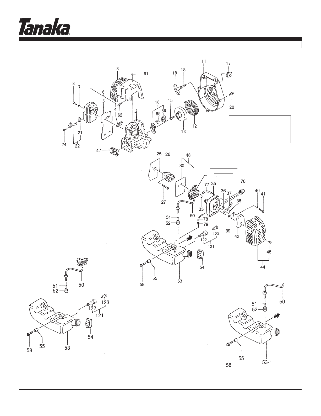
ENGINE, MUFFLER, AIR CLEANER, FUEL SYSTEM • FIGURE 2
THT-2100
Recoil Starter Assy
Use #762.06500.90
Includes items #11-#19
CARBURETOR
SEE FIG-3
www.tanakapowerequipment.com
Page 3
custsvc@nikko-tanaka-usa.com
Page 5

PARTS INFORMATION
THT-2100
ENGINE, MUFFLER, AIR CLEANER, FUEL SYSTEM • FIGURE 2
ITEM PART NUMBER DESCRI PTION QTY COMMENTS
2-3 7380650020 PROTECTOR,MUFFLER 1
2-4 73706500200 GASKET,MUFFLER 1
2-5 13306500200 SHIELD,HEAT 1
2-6 7040651C90 MUFFLER,SET 1
2-7 99201050011 WASHER,5 2
2-8 99051050503 BOLT,HEX,5X50 2
2-11 1120650080 CASE,FAN 1
2-12 78006097200 SPRING,RECOIL 1
2-13 77406097200 PULLEY,STARTER 1
2-15 8390201020 SCREW,SET 1
2-16 79806500900 PULLEY,STARTER,ASS'Y 1
2-17 2030604A202 GROMMET 1
2-18 78306097200 ROPE,STARTER 1
2-19 78506410200 HANDLE,STARTER 1
2-20 99415040162 SCREW,PS,4X16 3
2-21 75106500200 GASKET,MUFFLER 1
2-22 7210650090 PIPE, TAIL 1
2-24 99434040081 SCREW,4X8/S 2
2-25 40306500200 GASKET,INTAKE 1
2-26 4040650090 SET,CARB INSULATOR 1 Includes carburetor gasket
2-27 99416050252 SCREW,5X25WS 2
2-30 40206500200 GASKET,CARBURETOR 1
2-33 99967015000 O-RING,P15 1
2-35 4230650081 BODY,CLEANER 1
2-36 47006500200 COLLAR 2
2-37 5280650T20 LEVER,CHOKE 1
2-38 99204080030 WASHER,8 1
2-39 47601700200 BOARD,BLOW OVER CHECK 1
2-40 99210050012 WASHER,S,5 2
2-41 99011050602 SCREW,5X60 2
2-43 4460650020 ELEMENT,CLEANER 1
2-44 4520650091 COVER, CLEANER W/BOLT 1
2-45 3800637C200 BOLT,CLEANER COVER 1
2-47 2770634F900 CLUTCH,ASS'Y 1
www.tanakapowerequipment.com
Page 4
custsvc@nikko-tanaka-usa.com
Page 6

PARTS INFORMATION
THT-2100
ENGINE, MUFFLER, AIR CLEANER, FUEL SYSTEM • FIGURE 2
ITEM PART NUMBER DESCRI PTION QTY COMMENTS
2-50 2230650090 PIPE,FUEL,ASS'Y 1
2-51 68000731201 CLIP 6.3 1
2-52 6750404280 FILTER,FUEL 1
2-53 5910650000 TANK.FUEL 1 Before S/N T245720
2-53 5910661321 TANK.FUEL S/N T245721 to U244200
2-53 5910651A21 TANK,FUEL 1 S/N U244201 and after
2-54 5950650A90 TANK CAP 1 Before S/N T245720
2-54 5950656B90 CAP,FUEL BLA CK,NON VENT 1 S/N T245271 and after
2-55 65900801200 COLLAR 2
2-58 99463050185 BOLT,HEX 5X18PS 2
2-61 99072045164 SCREW,TAPPING,4.5X16 1
2-62 99425040128 BOLT,PS,4X12 2
2-65 79006097200 SPRING,STARTER PAW L 1
2-66 7880650020 PAWL,STARTER 1
2-70 44225143800 PUMP,PRIMING A SS'Y 1 S/N U244201 and after
2-77 70002504080 PIPE,FUEL,2.5X4X80 1 S/N U244201 and after
2-78 7000250406 PIPE,FUEL,2.5X4X65 1 S/N U244201 and after
2-79 53432710200 GROMMET,FUEL PIPE 1 S/N U244201 and after
2-121 56400661190 VENT,AIR ASS'Y 1
2-122 5650441020 PIPE,AIR VENT 1
2-123 5640098190 AIR VENT VALVE ASSY 1
www.tanakapowerequipment.com
Page 5
custsvc@nikko-tanaka-usa.com
Page 7

PARTS INFORMATION
THT-2100
CARBURETOR • FIGURE 3
A small retainer (560-02170-
20), has been added to this
model after serial # A099801
to prevent the barrel end of the
throttle wire from coming
detached from the carburetor.
ITEM PART NUMBER DESCRIPTION QTY COMMENTS
3-0 4550650090 CARBURETOR,SET 1 Before S/N U244200 3-0 4550651A90 CARBURETOR 1 S/N U244201 and after 3-1 54825140200 SCREW,THROTTLE SET 1 3-5 53925120200 SWIVEL 1 * Contained in Carb Repair Kit 3-7 48925100200 RING,STOP 1 P/N 650-25124-900 (Not available individually) 3-10 55025100200 O-RING 1 3-11 5992000W35 JET, MAIN,#35 1 Before S/N U244200 3-11 599200BW34 JET,MAIN,LONG,#34.5 1 S/N U244201 and after 3-13 ~ ~ ~ *GASKET,PUMP 1 3-14 ~ ~ ~ *DIAPHRAGM, PUMP 1 3-17 ~ ~ ~ *SCREEN,INLET 1 3-18 5752518280 BODY,PUMP 1 Before S/N U244200 3-18 5752514780 BODY,PUMP AS S'Y 1 S/N U244201 and after 3-19 ~ ~ ~ *GASKET,DIAPHRAGM 1 Before S/N U244200 3-19 ~ ~ ~ *GASKET,DIAPHRAGM 1 S/N U244201 and after 3-20 ~ ~ ~ *DIAPHRAGM,METERING 1 3-21 47625004200 COVER,DIAPHRAGM 1 3-22 54825101200 SCREW,SET 4
www.tanakapowerequipment.com
Page 6
custsvc@nikko-tanaka-usa.com
Page 8

PARTS INFORMATION
sn A302051 and after
THT-2100
GEAR CASE, CUTTER BLADES • FIGURE 4
www.tanakapowerequipment.com
Page 7
custsvc@nikko-tanaka-usa.com
Page 9

PARTS INFORMATION
THT-2100
GEAR CASE, CUTTER BLADES • FIGURE 4
ITEM PART NUMBER DESCRIPTION QTY COMMENTS
4-1 3003317A80 CASE,GEAR 1
4-2 99350015002 RING,STOP,C-15 EX 1
4-3 99961600200 BEARING,BALL,#6002 1
4-4 99961600202 BEARING,BALL,#6002Z 1
4-5 2883318080 DRUM,CLUTCH 1
4-6 30533160200 SHAFT,GEAR 1
4-7 07533160200 PLATE,GUIDE 1
4-8 1013316022 ROD,CAM 2
4-9 3073318020 GEAR,2 1
4-10 30333160200 GASKET,GEARCASE 1
4-11 6303316020 COVER,GEAR CASE 1
4-12 1223316021 GUIDE,CUTTER 625MM 1 ~A302050
4-12 1223317820 GUIDE,CUTTER 1 A302051~
4-13 1363316020 PLATE,PROTECTION 1 S278771~
4-14 99052060165 BOLT,HEX,6X16 2 ~A302050
4-14 99052060255 BOLT,HEX FLUSH,6X25 2 A302051~
4-15 CB-21A BLADE,CUTTER,THT-210/2100 2
4-16 08533160200 SEAL,GREASE A 2
4-17 12933202201 WASHER,7 4
4-18 1243320221 BOLT,CUTTER FIXING,A 4 ~A302050
4-18 1243228720 BOLT,FIXING,A,M6 4 A302051~
4-19 1233317A20 NUT,CUTTER FIXING 4 Y004401 thru A302050
4-19 40927 NUT,FLANGE,6 3 A302051~
4-21 99461040104 BOLT,HEX,4X10,S 8 ~A302050
4-21 99461040124 BOLT,HEX,4X12,S 6 A302051~
4-22 30032250801 FITTING,GREASE 2
4-23 99051060143 BOLT,HEX,6X14 2
4-30 4623329520 PLATE,SUPPORT 1 A302051~
4-31 8713260020 WASHER SPECIAL A 1 A302051~
4-32 99187060001 NUT 3 A302051~
4-60 3013316021 GEAR CASE B 1 A302051~
4-67 19805015800 CLAMP,CORD 1
4-69 13833160200 COVER,CUTTER,22" 1 ~S278770
4-69 1383316820 COVER,CUTTER,22" 1 S278771~
4-71 99210060012 WASHER,S,6 2
4-72 99440060011 NUT,SPRING 6 2
4-81 99201060011 WASHER,6 3 S278771~
4-82 99461040104 BOLT,HEX,4X10,S 2 A302051~
www.tanakapowerequipment.com
Page 8
custsvc@nikko-tanaka-usa.com
Page 10

PARTS INFORMATION
HANDLE, THROTTLE LEVER • FIGURE 5
THT-2100
ITEM PART NUMBER DESCRIPTION QTY COMMENTS
5-26 1703317A80 SWITCH,STOP 1
5-27 2581165020 BUTTON,STOP 1
5-28 99011030101 SCREW,3X10 1
5-29 2303315020 LEVER,THROTTLE 1
5-30 23133150200 LEVER,SAFETY 1
5-31 23233150200 SPRING,THROTTLE LEVER 1
5-35 7653212020 CAP 1
5-36 99311040182 SCREW,TAPPING 4x18 7
5-47 8850651C80 W IRE,THROTTLE 1
5-48 9253253020 DECAL,STOP BUTTON 1
5-50 99414050451 SCREW,5X45/S 1
5-51 99178050010 NUT,LOCK 5 1
5-53 99414060181 SCREW,6X18/S 1
5-55 99200050011 W ASHER,SMALL,5 1
5-61 2103316021 HANDLE 1
5-64 99210050062 W ASHER,S,5 2
5-63 99201050061 W ASHER,5 2
5-65 99051050403 BOLT,HEX,5X40 2
5-73 1640701400 TUBE, PROTECTION 140L 1
5-82 65900801200 COLLAR 2
5-83 05033150010 HANDLE ASS'Y 1 Includes both left and right handles
www.tanakapowerequipment.com
Page 9
custsvc@nikko-tanaka-usa.com
Page 11

PARTS INFORMATION
THT-2100
DECALS • FIGURE 6
ITEM PART NUMBER DESCRI PTION QTY COMMENTS
6-1 95037900200 DECAL,PRO-FORCE A 1
6-2 9060651C20 DECAL,THT-2100 1
6-5 95137900200 DECAL,PRO-FORCE 1
6-8 91106500200 DECAL,SRS 1
6-17 9203246620 DECAL,CAUTION 1
6-27 9083316021 DECAL,CAUTION 1
www.tanakapowerequipment.com
Page 10
custsvc@nikko-tanaka-usa.com
Page 12

TECHNICAL SERVICE BULLETIN NUMBER PI 3118
June 2001
Date:
Model & Serial:
All units produced after serial number W100101.
Reason:
When these units are fitted with the aluminum safety shield, some experience
Models THT-2100, 2120, 2510 and HTD-2526PF, 2522PF require 3 washers.
Models THT-2520, 2540 and HTS-2530PF and HTD-2530PF require 2 washers
Part Number Changes:
Old Part # New Part # Description Remarks
992-01060-011 Washer
THT-2100/THT-2120/THT-2510/THT-2520/THT-2540/HTD-2522PF/HTD-2526PF/HTD-
2530PF/HTS-2530PF.
loosening of the blade jam nuts. A flat washer has been added between the nut
and the aluminum shield to help prevent the nut from becoming loose.
Nikko Tanaka Engineering U.S.A. ,Ltd.• 1028 4
th
Street SW, Bldg B • Auburn, WA 98001 • Phone: (253) 333-1200 • Fax: (253) 333-1212
Page 13

TECHNICAL SERVICE BULLETIN NUMBER PI 3119
January, 2002
Date:
Model & Serial:
All units after
Reason:
All future production of hedgetrimmer models will utilize a blade-retaining nut
When adjusting blade-fastening hardware, thread the bolt (18) through the
Part Number Changes:
Old Part # New Part # Description Remarks
123-33202-200 123-3317A-20 Lock Nut Reference #19
All THT, HTD, HTS, TPH hedgetrimmer models.
serial number Y004401
that is of the locking variety. These nuts are oblong on one side to prevent
loosening during use, but can be removed and re-installed without losing their
locking ability.
blades and guide bar from the bottom, to a point where the flat washer (17), is
still able to rotate, (usually to seat, and then backed off between ¼ and ½
revolution). Then install the lock nuts on the topside, tightening them while
holding the bolt in place. Tighten all nuts, and then re-check for adjustment prior
to operation. A lubricating agent, such as WD-40 should also be used to prevent
sap build-up and premature wear.
Nikko Tanaka Engineering U.S.A. ,Ltd.• 1028 4
th
Street SW, Bldg B • Auburn, WA 98001 • Phone: (253) 333-1200 • Fax: (253) 333-1212
Page 14

TECHNICAL SERVICE BULLETIN NUMBER PI 3129
December 2004
Date:
Model & Serial:
A302051 and later
Reason: Configuration standardization of hardware, converting blade hardware from US
Comments:
Part Number Changes:
THT-2100
Standard thread to Metric thread. An additional support plate is also being added
to this product to strengthen the cutter guide.
Please verify serial number on unit prior to ordering replacement blade hardware
and add the support plate on older serial numbers. The support plate qualifies
for warranty reimbursement at .25 hours and normal parts rate.
Description Old parts # New parts #
Cutter guide 625.5L M6 (#12) 122-33160-21 122-33178-20
Cutter fixing bolt A 124-33202-21 124-32287-20
Flange nut M6 (#19) 123-3317A-20 991-82060-001
Hex hole flush bolt 6x255 (#14) 990-52060-165 990-52060-255
Protection plate 390L (#13) 136-33160-20
Keep same pcs & reuse some
Washer 6 (#33) 992-01060-011
Hex hole bolt 4x10S (#82) 994-61040-104
Hex hole bolt 4x12S (#21) 994-61040-104 994-61040-124
Special washer B 2.0 (#31) 871-32600-200
Gear case B (#60) 301-33160-21
Support plate (#30) 462-33295-20
Nut 6 UPS-P (#32) 991-87060-001
Front handle 210-33160-21 210-33160-22
for protection plate
Nikko Tanaka Engineering U.S.A. ,Ltd.• 1028 4
th
Street SW, Bldg B • Auburn, WA 98001 • Phone: (253) 333-1200 • Fax: (253) 333-1212
 Loading...