

Page 1

Model Numbers:
Owner’Owner’
Owner’
Owner’Owner’
s Mans Man
s Man
s Mans Man
ualual
ual
ualual
AST-7000AST-7000
AST-7000
AST-7000AST-7000
AA
UTUT
A
AA
UT
UTUT
O-STO-ST
O-ST
O-STO-ST
ARAR
T TRIMMERT TRIMMER
AR
T TRIMMER
ARAR
T TRIMMERT TRIMMER
Date 04-19-01
ISM, Inc. • 1028 4th Street SW • Auburn, WA 98001 • Phone: (253) 333-1200 • Fax: (253) 333-1212
www.tanakapowerequipment.com custsvc@tanaka-ism.com
Supplier To The Outdoor Power Equipment Industry
Page 2
AST-7000
Owner’s Manual
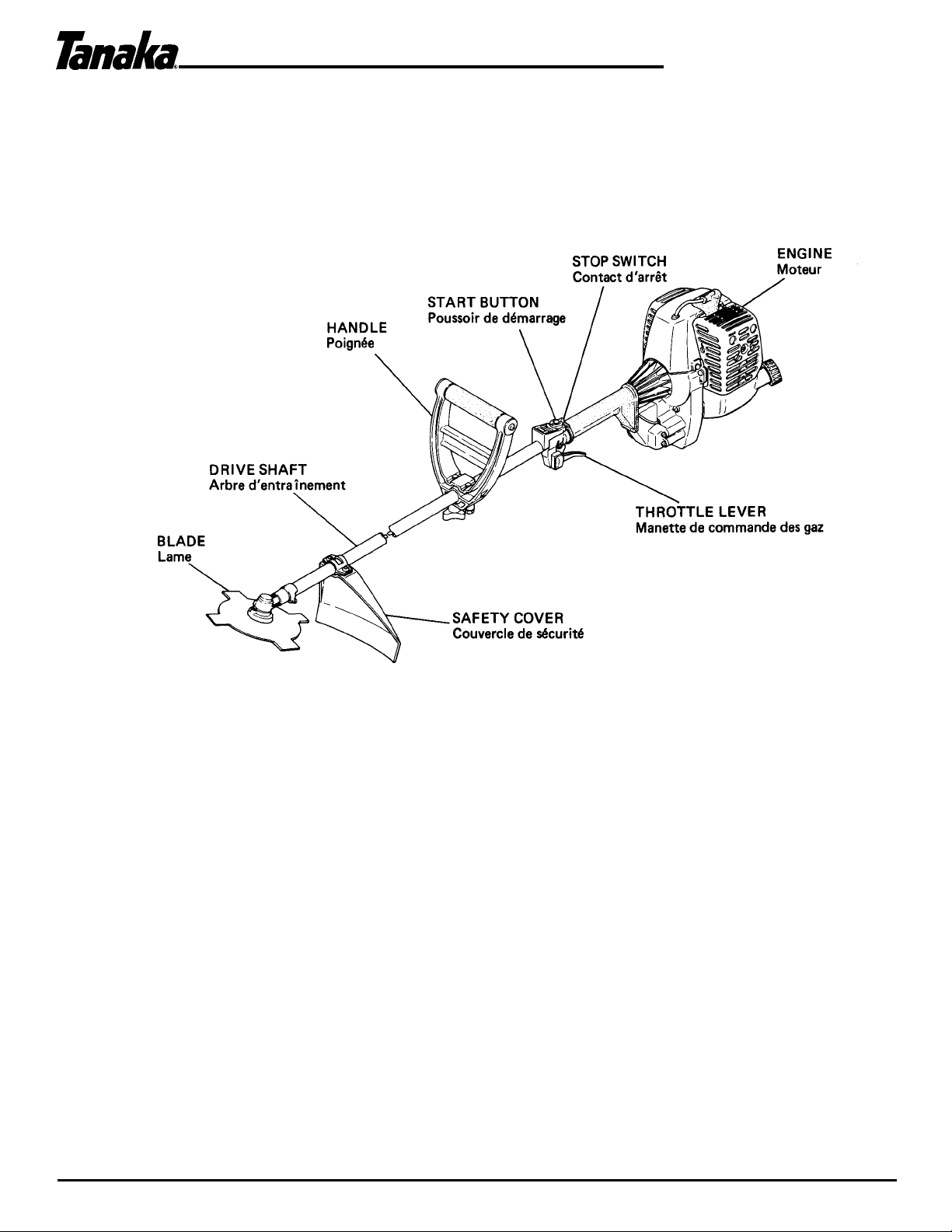
Major Parts
Since this manual covers several models, there may be some difference between pictures and your unit.
www.tanakapowerequipment.com 1 custsvc@tanaka-ism.com
Page 3

AST-7000
Owner’s Manual
GENERAL INSTRUCTIONS FOR SAFETY OPERATION
All the TANAKA products are delivered with an Owner's manual. Please read it carefully to get acquainted with the
operation of your unit. For further details, inquire at your nearest dealer.
Before Operation
• Protect head (eyes and ears), feet and hands with safety hat, ear cover, goggles, safety shoes and protective
clothes.
• Dress properly, do not wear loose clothing or jewelry that could become caught in moving parts of the unit.
• Never let a child or inexperienced person operate the machine.
• Be sure to check bolts and other fasteners to see if any of them have become loose or are missing.
Cutting Blade
• The cutter blade is very sharp. Take care not to touch it carelessly.
• To assemble the blade correctly, read the instructions in this manual thoroughly.
• As the cutter fixing bolt is left threaded, special care is required to fix the blade firmly.
Fuel
• Fuel for this engine requires a mix of regular gasoline and Tanaka brand 2 cycle, oil. Never operate the engine
with unmixed or straight gasoline.
• Never remove the tank cap or refuel the tank while the engine is running. Always shut off the engine and allow it
to cool before refueling.
• Never smoke when handling fuel or operating your equipment, or maintaining your equipment.
• Never allow fire or flame near the fuel or equipment.
• WARNING! Gasoline is an extremely flammable fuel. Use extreme caution when handling gasoline or fuel mix.
• Fuel should be stored in a dry and cool place.
During Operation
• The unit should be operated in a well ventilated area.
• Keep children away. Onlookers should be kept at a safe distance from the work area, at least 25 feet (7-8
meters). Keep all parts of your body and clothing away from the blade when starting or running the engine.
• While cutting, hold the machine firmly with both hands with thumb firmly locked around front handle, and stand
with feet well-balanced and your body balanced.
• The operator must obey the local regulations of cutting area.
• Never carry the unit with the engine running.
• When making a repair or adjustment, the unit must be stopped and the fuel completely drained.
• When operating in a dry area, the operator is advised always to carry a fire extinguisher.
• The unit must not be used without the safety guard.
For Long-term Storage
• Drain all fuel from the carburetor, fuel tank and fuel lines.
• Repair any damage which has resulted from use.
• Clean the unit with a clean rag, or the use of a high pressure air hose.
• Put a few drops of engine oil into the cylinder through the spark plug hole, and spin the engine over several times
to distribute the oil. Then replace the plug in the plug hole.
• Cover the unit and store it in a dry area.
CAUTION: The steel blade rotates counter-clockwise therefore it is important to operate the blade from right to left
which eliminates the risk of injury.
CAUTION: If the blade should strike a solid object, stop the engine immediately and check for damage. Do not use a
blade which has been damaged in any way.
www.tanakapowerequipment.com 2 custsvc@tanaka-ism.com
Page 4

AST-7000
Owner’s Manual
I. IMPORTANT SAFETY INSTRUCTIONS
1. Do not depress the "Start Button" while recharging the battery. This will result in damage to the
battery charger. The battery charger must be disconnected from the unit before starting.
2. Do not attempt to charge the AST-7000 battery with other than the Tanaka charger. Do not attempt to
charge other batteries with the Tanaka charger. The charger and the AST-7000 battery have specific
voltage requirements and are designed only to work together.
3. The charger is designed for standard household electrical power (AC 120V). Do not attempt to use any
other voltage.
4. Do not expose the charger to rain or snow.
5. Do not store the AST-7000 or charger where temperatures will meet or exceed 122° F(62°C).
6. Do not short circuit or in any way alter the charging system as this will result in damage to the battery
and/or the unit.
7. Do not store or operate near open flames as this may cause the battery to burst and/or release toxic
material.
II. ASSEMBLING PROCEDURES
1. Drive shaft to engine (Fig. 1)
1. Loosen shaft tightening bolt (1) and location bolt (2).
2. Insert the throttle wire (4) through the hole in the bottom of
the shaft grip and connect the electrical coupling (3).
3. Push the drive shaft into the hole in the clutch case until the
shaft grip is against the clutch case.
NOTE: If the shaft does not slide so that the grip is against the
clutch case, turn the drive shaft slightly in order to match the
splined end of the drive shaft with the splined clutch drum inside of
the clutch case.
4. Tighten the location bolt (2) and the shaft tightening bolt (1 ).
2. Throttle control (Fig. 2)
1. Remove throttle lever screw (1) and slide the throttle lever assembly
away from the shaft grip temporarily. Connect the throttle wire in
the hole of the throttle lever.
2. Locate throttle lever in its original position by squeezing the trigger,
then slide the throttle lever assembly back against the shaft grip
then retighten the throttle lever screw (1 ).
3. Installation of handle (Fig. 3)
1. Secure the handle to the shaft as shown in Figure 3. Adjust the
handle according to your height, etc.
Note: Keep both triangular marks of handle and handle bracket on the
same side. Tighten the mark side (Hex. bolt) first, then, handle knob.
www.tanakapowerequipment.com 3 custsvc@tanaka-ism.com
Page 5

4. Installation of safety guard (Fig. 4 & 5)
1. Secure the safety guard to the shaft as shown in Figure 4.
NOTE: The safety guard must be installed 5" from the top of the gear case as shown in figure 5. If this is not
done the safety guard may be damaged by the nylon line and the guard may not protect the operator against any
flying debris.
AST-7000
Owner’s Manual
5. Installation of cutting attachments (Fig. 6 & 7)
1. Insert the allen-head wrench into the hole on the top of the gear case to lock the output shaft. Then install the
nylon head as shown in Figure 6 or the blade as shown in Figure 7.
NOTE: The blade fixing bolt (1) and the cutting head adapter bolt (2) are left-handed thread.
III. OPERATING PROCEDURES
1. Fuel (Fig. 8)
1. For proper lubrication, this engine must operate on a mixture of
gasoline and Tanaka brand 2-cycle engine oil. Tanaka 2 cycle oil has
been formulated to insure maximum engine performance and,
increased engine life. The gasoline must be mixed according to the
instructions on the oil bottle. If Tanaka oil isn't available, mix 50 parts
of regular gasoline to 1 part of quality 2 cycle mix.
CAUTION: Do not use gasoline containing alcohol or gasohol as this
may result in engine failures.
www.tanakapowerequipment.com 4 custsvc@tanaka-ism.com
Page 6

AST-7000
(III. Operating Procedures cont.)
2. Starting Procedure
The AST-7000 battery is not fully charged at the factory. It is necessary to charge it fully
before operation. Please follow "Charging Procedures". See Item 5.
1. Depress the priming bulb (3) several times until fuel flows through the bulb
into the carburetor. Depress the fuel injection button (4) once which transfers
fuel from the carburetor to the combustion chamber.
(See Fig. 9)
NOTE: When the engine is warm it is not necessary to depress the priming
bulb or the fuel injection button when starting. If this is done, the engine may
become flooded and hard to start.
2. Turn the switch to the "On" (1 position and depress the start button (2) until
the engine starts. Warm the engine by running at idle speed for 2 to 3
minutes. (See Fig. 10)
CAUTION: Do not depress the "Start Button" for more than 10
seconds continuously, as this may cause premature power drainage
of the batteries.
3. If the engine does not start:
1. If the engine starts but does not continue to run, repeat steps 1 and 2.
2. If the engine does not f ire, squeeze the throttle lever (3), push the lock button
(4), then repeat step 2.
(See Fig. 11 )
CAUTION: With the throttle lock engaged the engine will run at a high
enough RPM to turn the cutting attachment.
3. If the starter does not make any noise, repeat the charging procedures. See Item
5.
4. To start the AST-7000 with the recoil starter follow starting procedure number 1 .
and turn the switch to the "On" position then pull the recoil starter handle briskly.
(See Fig. 12)
4. Stopping the Engine
1. Decrease the engine speed by releasing the throttle lever then turn the On/Off
switch to the Off position.
(See Fig. 10)
5. Battery Charging Procedures
The AST-7000 has a self-charging system, however, it may require charging if the unit is
stored and the battery output becomes low.
1. Plug the battery charger (2) into a household electrical outlet (1 20v Only) and
connect the electrical coupling (3) to the coupling on the top of the throttle lever
assembly. (See Fig. 13)
CAUTION:
! Do not leave the charge plugged in for more than 24 hours.
! Do not charge battery when temperature is below 32°F (0°C) or
above 113° (45°C). If this is done the battery may not accept a full
charge.
Owner’s Manual
NOTE: When completely discharged the battery will take approximately 15 hours to charge.
www.tanakapowerequipment.com 5 custsvc@tanaka-ism.com
Page 7

AST-7000
(III. Operating Procedures cont.)
6. Carburetor adjustment: (Fig. 14 & 15)
The carburetor has been preset at the factory and probably won't require adjusting. It is
recommended that any carburetor adjustments or engine adjustments be done by your
local TANAKA service dealer. If an adjustment is necessary, follow these below
procedures:
1. Start the engine and allow it to warm up for 5 minutes.
2. Release the throttle lever and allow it to run at idle speed.
3. With the engine idling, turn the idle limiter (I ) clockwise or counterclockwise to
achieve the maximum engine RPM. Then turn the idle limiter counterclockwise
one notch.
(See Fig. 14)
NOTE: Counterclockwise rotation richens the mixture and clockwise
rotation makes the mixture leaner.
4. Next with the engine at wide open throttle turn the "H Screw" (1) clockwise or
counterclockwise to achieve the maximum engine speed. Then turn the "H
Screw" counterclockwise 1/4 turn. Now, the H screw should be set between 1
-1 /4 and 1 -3/4 turned counterclockwise from lightly seated position. (See Fig.
15)
5. Appropriate idle speed is the position where blade does not turn or engine does
not stall. When the idle speed is too low or too high, adjust it with idle screw
(2). (See Fig. 15)
CAUTION:
! Lean carburetor settings can cause serious engine damage.
! Do not attempt to adjust the screw inside of the idle limiter.
Owner’s Manual
IV. MAINTENANCE
1. Periodical check
1. Clean air cleaner element (1) with soap and water and dry before reuse. (Fig.
16)
2. Scrape off the carbon from the spark plug gap. (Standard gap is 0.6 mm or
0.023 in.). (Fig. 17)
3. Clean the cylinder exhaust port and muffler. Remove grass or dust that has
entered in the cylinder cover or fan case cover. (It may cause trouble such as
overheating.)
4. Inspect carefully for any fuel or oil leaks.
5. Check all nuts, bolts, screws, etc., making sure they are tightened.
6. The clutch shoes will wear after a long period of use, they should be checked
occasionally.
7. Lubricate Gear Case every 50 hours of use.
www.tanakapowerequipment.com 6 custsvc@tanaka-ism.com
Page 8

AST-7000
(IV. Maintenance cont.)
2. Blade
1. When replacing blade, purchase one recommended by TANAKA, with a
25.4 mm (one inch) fitting hole.
2. When installing saw blade, always face the stamped side up. In the case
of a 4 tooth blade, it can be used on either side.
3. Use correct blade for the type of work.
4. When replacing blade, use appropriate tools.
5. When cutting edges become dull, re-sharpen or file as shown in figure.
Incorrect sharpening may cause excessive vibration.
3. Storage (For more details, refer to General Instructions in page 2.)
1. Completely drain fuel out of tank and run engine until it stops.
2. Clean the unit carefully and keep it from moisture.
3. In the case of transport or storage, switch off the engine.
4. When transporting in a vehicle, keep blade covered with blade cover.
Owner’s Manual
V. Specifications
www.tanakapowerequipment.com 7 custsvc@tanaka-ism.com
 Loading...