

Page 1
PROFESSIONAL CUTTING HEADS
5” SEMI-AUTO PACKAGED CUTTING HEAD
ITEM NUMBER: 746451
Owner’s Manual
(#27976 - Page 1)
Safety Instructions
1.) *Warning! Read this owners manual as well as the
owners manual supplied with your grass trimmer. Be sure to
follow all warnings and safety instructions. Failure to do so
can result in serious injury to the operator and/or bystanders.
2.) Wear eye protection that complies with ANSI Z87-1 std.
3.) Do not operate power equipment when you are tired, ill,
or under the influence of alcohol, drugs, or medication.
4.) Always wear heavy long pants, boots, and gloves. Do not
wear loose clothing, short pants, sandals, or go bare foot. Secure
hair so it is above shoulder level.
5.) Inspect unit before each use. Replace parts that may be
cracked, chipped, or damaged in any way . Make sure the cutting
head is properly installed and securely fastened. Be sure tthe
cutting attachment shield is properly attached in the position
recommended by the manufacturer.
6.) Clear the work area before each use. Remove all objects
such as rocks, broken glass, nails, wire, or string which can be
thrown or become entangled in the cutting head. Clear the area
of children, bystanders, and pets in a 50 foot (15m) radius. It is
recommended that bystanders wear eye protection. If you are
approached, stop the engine and cutting attachment immediately .
Installation
The following instructions are based on mounting the head to
T anaka units. Other brands of product may be similar , however
be sure to check the unit’s owner’s manual for proper procedures.
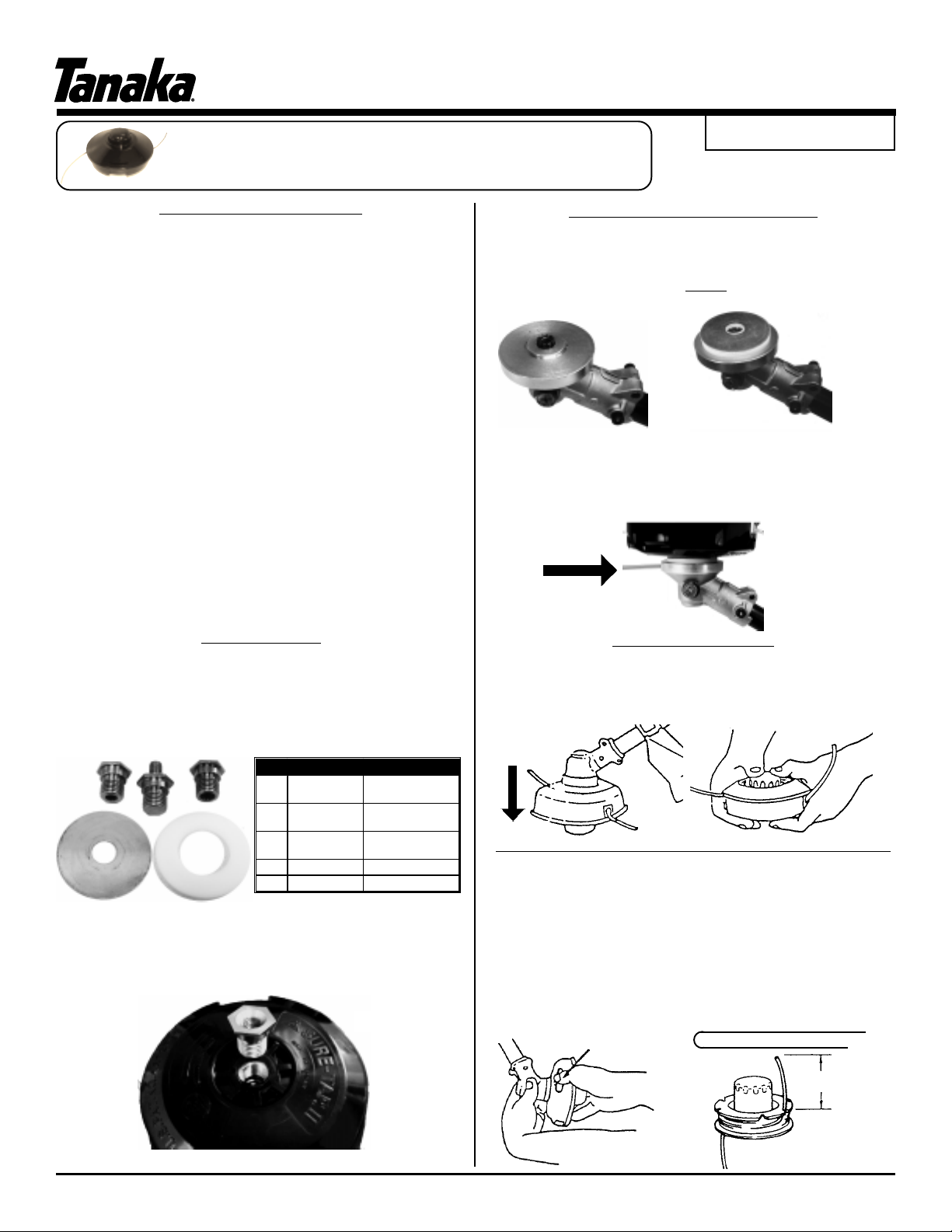
The package comes standard with the following mounting
components:
1-1
1-4
The head comes standard with a 10mm x 1.25 LHF adapter (Ref.
1-3 in chart above). T o change the adapter , loosen /remove (with
a 19mm wrench or socket) by turning counter-clockwise (Ref. 2).
1-2
1-5
1-3
Ref.# Pa rt No. Description
1-1 365-3383E-200
1-2 356-33830-200
1-3 356-3383B-200
1-4 29729 Mounting Washer
1-5 17W20004 Mounting Spacer
Adapter Nut
(8mm x 1.25 LHF )
Adapter Bolt
(8mm x 1.25 LHM)
Adapter Nut
(10mm x 1.25 LHF )
Ref. 2
Installation (continued)
Many gear cases utilize a separate piece or cover which includes
a mounting shoulder which is used to hold and center cutting
blades as shown in Ref. 3. On T anaka units, for the 5” Semi-Auto
head to be held flush and tight, BOTH the mounting spacer (first)
and washer (second) must be used as shown in Ref. 4.
Ref. 3
Ref. 4
Once the spacers and head have been attached, rotate the
cover to the front of the gear case until you can insert a long /
small diameter metal object (such as a small screwdriver or hex
wrench included with all T anaka units) into the locking hole as
shown in Ref. 5. Tighten the cutting head by turning it counterclockwise.
Ref. 5
Extending Line
When nylon line becomes shorter, reduce engine speed
and tap the cutting head on the ground as shown in Ref. 6.
T o extend nylon line by hand, push in on the bottom of the head
(after engine has been stopped) and rotate as shown in Ref. 7.
Ref. 6
Ref. 7
Disassembly / Nylon Line Installation
Press in on the two locking slots of the inner housing as shown in
Ref. 8. Pull inner housing from the outer housing and
remove spring and spool from the outer housing. Fold the
line in half (the head will hold up to 25’ of .095” dia. line.) so
that one end is approx. 3 inches longer than the other.
Insert the folded end in to the slot of the center partition of
the spool and wind the nylon line in the direction marked
“Wind Cord”. Leave approx 3 inches of line on each end
and lock in to the appropriate slots on the spool as shown
in Ref. 9
3” / 10cm
Ref. 8
ISM, Inc. • 1028 4th St. SW • Auburn, WA 98001 • Phone: (253) 333-1200 • Fax: (253) 333-1212 • www.tanakapowerequipment.com
Ref. 9
-Parts breakdown on back-
Page 2
PROFESSIONAL CUTTING HEADS
5” SEMI-AUTOMATIC CUTTING HEAD
ITEM NUMBER: 746451
Owner’s Manual
(#27976 - Page 2)
Cutting Head Assembly
Place the spool into the inner housing. Pass both line
ends through the eyelets and remove the lines from the
locking slots of spool as shown in Ref. 10. Place the
return spring into the spool, then place the outer housing on
the inner housing and assemble firmly by pushing the two
locking slots with thumbs as shown in Ref. 1 1. Adjust nylon
line to desired length by pushing in on the tap button and
turning the spool.
Ref. 1 1Ref. 10
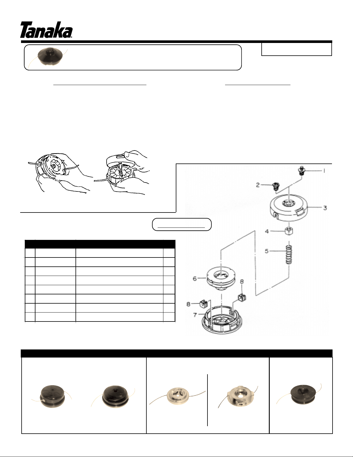
Parts List
Re f Par t Nu mb er Par t Descrip tio n Qty
1 356-33830-200 Adapter, 8mm x 1.25mm LH Male 1
2 356-3383B-20 0 Ad apter, 1 0m m x 1. 25 m m LH F em a l e 1
3 786-338 30-20 0 Body, Nylon Cord 1
4 315-338 30-20 0 Nut, Sp ecial 1
5 793-338 30-20 0 Spri ng, Reel 1
6 787-338 30-20 0 Reel, Nylo n Cord 1
7 789-338 30-20 0 Cap, Body 1
8 788-338 30-20 0 Eyelet 2
Troubleshooting
Problem: Nylon line is not feeding.
Possible Causes:
1.) Nylon line is almost used up.
2.) The lines have been deformed .
3.) The lines have become intertwined.
Solutions:
1.) Disassemble the cutting head.
2.) Remove nylon line from the spool and rewind.
3.) Replace the nylon line if the line is almost gone or deformed.
4.) Reassemble the cutting head.
TANAKA OFFERS OTHER HIGH QU ALITY CUTTING HEADS
FULL Y AUTOMA TIC
The Original
BRAIN
Order # 746251
Std. Line Diameter: .095”
Line Capacity: 30ft. / 9.1m
ISM, Inc. • 1028 4th St. SW • Auburn, WA 98001 • Phone: (253) 333-1200 • Fax: (253) 333-1212 • www.tanakapowerequipment.com
®
The BRAIN
2000
Order # 746751
Std. Line Diameter: .095”
Line Capacity: 20 ft./ 6.7m
®
HEAVY-DUTY COMMERCIAL
Aluminum Fixed
Line
Order # 746280
Std. Line Diameter: .130”
Line Capacity: N/A
Aluminum Manual
Feed
Order # 746290
Std. Line Diameter: .105”
Line Capacity: 15ft / 4.5m
Manual Feed
Order # 746551
Std. Line Diameter: .095”
Line Capacity: 25ft / 7.6 m
 Loading...