

TAMUZ SPARROW HAWK LSM 124W, SPARROW HAWK LSM 127W, SPARROW HAWK LSM 132W, SPARROW HAWK LSM 137W, SPARROW HAWK LSM 142W Operation Manual
...
Operation Manual
SPARROW HAWK series
LSM 124W - LSM 127W
LSM 132W - LSM 137W - LSM 142W - LSM 147W
LSM 152W - LSM 157W - LSM 165W - LSM 182W
TAMUZ LCD Video Monitors
D-24558 Henstedt-Ulzburg ~ Fon & Fax: ..49 - (0)700 - TAMUZLCD [82 689 523]

All rights reserved. No part of this work may be reproduced or duplicated or spread or processed
under use of electronic systems, in any form (print, photocopy, microfilm or other proceedings),
without written permission of the right owner.
Alle Rechte vorbehalten. Kein Teil dieses Werkes darf in irgendeiner Form (Druck, Fotokopie, Mikrofilm
oder anderen Verfahren) ohne schriftliche Genehmigung des Rechteinhabers reproduziert oder unter
Verwendung elektronischer Systeme verarbeitet, vervielfältigt oder verbreitet werden.
Concept, Publishing and Production: E.L.B.E medi@, Henstedt-Ulzburg
Printed in Germany
I. Issue LSM SPARROWHAWK Digital Broadcast Monitor
valid for Firmware Release 5.062 and above
© 2006-2007 Copyright by:
TAMUZ - LCD Video Monitors
a division of
TAMUZ Broadcast GmbH
Fon & Fax: +49 - (0)700 TAMUZLCD [82 689 523]
eMail: info@tamuz.tv
www.tamuz.tv
Rights reserved to change specifications and design without notice
Technische und farbliche Änderungen vorbehalten
© 02.07 TAMUZ - LCD Video Monitors LSM Digital Broadcast Monitor Page - 2 -

SPARROWHAWK Digital Broadcast Monitor
Table of Content
Introduction........................................................................5
LCD Video Monitor.........................................................5
SPARROWHAWK series Models........................................6
Differences in the series.................................................7
SPARROWHAWK Features.........................................7
ISO Product Quality........................................................8
Pixel Errors..................................................................8
Class of Usability.........................................................8
Class of Reflections.....................................................8
Wide Screen Format.......................................................9
Sampling the Video.................................................9
General Safety Instructions..............................................10
Limitation of the product..............................................10
Duty of care of the user................................................10
Safety symbols.............................................................10
Basic Safety Instructions..............................................11
Service and Maintenance..........................................11
Observe environmental protection prescriptions......11
Recycling......................................................................12
Recognition of the copyrights......................................12
Guarantee agreement:.....................................................13
Guarantee period......................................................13
Guarantee exceptions...............................................13
Guarantee Certification.............................................13
Warranty Card..................................................................14
Transport of the equipment.............................................15
Transportation..............................................................15
Weight.......................................................................15
Packing.........................................................................15
Return dispatch.........................................................15
Damages in transit....................................................15
Conformity Declaration....................................................16
Technical Data.................................................................17
System Hardware SPARROWHAWK series.................17
System Features SPARROWHAWK series...................18
Installation........................................................................19
First putting into Operation..........................................19
Mounting in 19“ Racks..............................................19
Mounting at VESA systems.......................................19
Ventilation.....................................................................19
Cleaning.......................................................................20
External Control Units...................................................20
Switching the Monitor on.............................................21
Power Save Mode.....................................................22
Suspend Mode......................................................22
Power Down Mode................................................22
Power Save Wake Up............................................22
Connections of the Monitor.............................................23
The Monitor Screen......................................................23
DC Voltage...................................................................24
Power Supply............................................................24
AC Voltage....................................................................24
Video Inputs at Version LSM 1xxW...........................25
DVI Inputs..................................................................25
Optional Input CCVS.............................................25
Signal Format............................................................25
Video Inputs at Version LSM 1xxW HD.....................26
DVI Inputs..................................................................26
Optional Input CCVS.............................................26
Signal Format........................................................26
HDTV Input................................................................27
VGA Input..................................................................28
Ethernet IP Interface.....................................................28
GPI/O Interface.............................................................29
Service Interface...........................................................30
Probe Interface.............................................................30
Operation.........................................................................31
Operation Elements at the SPARROWHAWK series....31
POWER Switch..........................................................31
Operation Buttons.....................................................31
Aspect Ratio Switch...............................................32
Size Switch............................................................34
R/G/B Switch..........................................................35
TALLY Indicator............................................................36
Option IR-Remote Controller........................................37
OSD Menu Operation......................................................38
OSD Menu....................................................................38
Main Menu ......................................................................39
Inputs Menu..............................................................40
Submenu Format for HDSDI inputs.......................41
Submenu HD Output..........................................42
Submenu HD Output - Testpattern....................42
Submenu HD Output – Rate Select.......................43
Submenu HD Output – Mode Search....................44
Submenu Format for SDI inputs............................45
Submenu WSS...................................................45
Submenu Format for CCVS inputs........................46
Submenu WSS...................................................46
Submenu Format for VGA inputs..........................47
Scaling Menu.........................................................48
Submenu Scan Mode............................................49
Submenu Mirror.....................................................50
Submenu Signal for HDSDI inputs........................52
Submenu P-I for interlaced HD-SDI Signals.......52
Submenu P-I for progressive HD-SDI Signals....54
Submenu Signal for SDI inputs.............................55
Submenu P-I interlaced for SD-SDI Signals.......55
Submenu Display..................................................58
Submenu Zoom.....................................................59
Submenu Reset.....................................................60
Image Menu..............................................................61
Submenu Gamma.................................................62
Submenu Color Temperature................................63
Submenu Color Adjustments................................65
Submenu B/W.......................................................66
Submenu Negative................................................67
Submenu R/G/B.....................................................68
Submenu Aperture................................................70
Keyboard Menu.........................................................71
© 02.07 TAMUZ - LCD Video Monitors LSM Digital Broadcast Monitor Page - 3 -

SPARROWHAWK Digital Broadcast Monitor
Submenu Keyboard...............................................72
System Menu............................................................73
Submenu Power On..............................................74
Submenu Search...................................................75
Submenu Processing............................................76
Submenu Language..............................................77
Submenu OSD.......................................................78
Submenu Wall.......................................................79
Submenu RGB Adjust............................................80
Submenu Auto Color.............................................81
Submenu Probe Setup.......................................82
Submenu Calibrate............................................83
Submenu Brightness..........................................84
Submenu Measure.............................................85
Submenu Backlight...............................................86
Submenu Anti Sticking..........................................87
How to minimize the effect?...............................87
Service Menu...................................................................89
Submenu Info........................................................90
Submenu MTBFs...................................................91
Submenu Setup.....................................................92
Submenu No Signal..............................................93
Submenu Temperatures........................................94
Submenu Aux1 Configuration...............................95
Submenu Aux2 Configuration...............................96
Submenu Aux3 Configuration...............................97
Submenu Backlight...............................................98
Submenu Firmware...............................................99
Individual Adjustments and Setups...............................100
Aspect Ratio Setup.....................................................100
Setup Instructions.......................................................100
Setup VGA Signals..............................................100
Setup HDTV Signals............................................101
Setup SDI Signals...................................................101
Setup CCVS Signals............................................102
Reset the Monitor.......................................................102
Special Formats..........................................................103
Setup BARCO VIVALDI........................................103
Setup SONY BVE.................................................104
Interfacing the BVE 2000..................................104
Disturbed BVE Images ....................................105
Modification at the BVE 2000...........................105
Block Diagrams..............................................................106
Blockdiagramm TFT Panels................................106
SPARROWHAWK LSM 1xxW...........................107
Alignment of LCD Monitors............................................108
Advantage of the TAMUZ AAC Technology............109
Color Alignment......................................................110
Quantization the video signal..............................111
How to align a TAMUZ monitor..................................112
Environment............................................................112
Alignment Setup......................................................112
Getting starting the Alignment................................112
Password for Alignment.......................................113
The Color Alignment Procedure.............................113
Starting Color Calibration.................................115
Starting Brightness Alignment..........................116
Starting Manual Measurement.........................117
Service Section .............................................................118
Changing a faulty Fuse..............................................118
1. Step: Open the Monitor...................................118
2. Step: Exchange the Fuse................................118
3. Step: Reassemble the Monitor........................118
Was kann an einem LCD Monitor repariert werden?.....119
Bemerkungen:.........................................................123
Genereller Service:..............................................123
Reset (Wiederherstellen der Fabrikeinstellungen):
.............................................................................123
Defekte Hintergrundbeleuchtung:.......................123
Defekter Controller:..............................................123
Neues Display:.....................................................123
Frequently Asked Questions..........................................124
Safety Notice..................................................................125
Remarques de sécurité..................................................126
Indicaciones de seguridad............................................127
Instruções de segurança...............................................128
Norme di sicurezza........................................................129
Sikkerhedsanvisninger...................................................130
Säkerhetsinformationer..................................................131
Turvallisuusohjeet..........................................................132
Sikkerhetsanvisninger....................................................133
Öryggisleiðbeiningar......................................................134
Veiligheidsvoorschriften.................................................135
© 02.07 TAMUZ - LCD Video Monitors LSM Digital Broadcast Monitor Page - 4 -

Introduction SPARROWHAWK
Introduction
LCD Video Monitor
The TAMUZ SPARROWHAWK series is a LCD monitor series with active TFT displays, designed as
a wall mountable or desktop unit for various video applications in studio or field production environment. It covers wide horizontal and vertical viewing angles at it best.
The wide screen displays allows full screen presentation of standard 16:9 videos (with no black areas
on top and bottom or left and right). In the user setup of the LSM xxxW HD version any other format is
individual adjustable.
The operation of the system was formed simply and user friendly. The SPARROWHAWK series monitors offers as basic version with DVI inputs as model LSM 1xxWW and a fully equipped version with
input ports for serial digital Standard-Definition and High-Definition video as model LSM 1xxWW HD.
All I/O ports are placed at the rear of the monitor, even the AC power connector for the integrated power supply. The SPARROWHAWK series monitors are equipped with a port for calibration probes.
Therefore the unique AAC (Automatic Alignment and Calibration) is a standard feature within the
SPARROWHAWK monitor series. Added option may be an Ethernet port for communication with external remote systems.
© 02.07 TAMUZ - LCD Video Monitors LSM Digital Broadcast Monitor Page - 5 -

SPARROWHAWK series Models SPARROWHAWK
SPARROWHAWK series Models
The SPARROWHAWK series signal processor contains a set of micro computer controlled DSP's
and scalers with native serial capability. Various models are available within the SPARROWHAWK
series.
Model / Interface Type Freq-V Hz Aspect Ratio
Screen
Resolutions
Input 1 Input 2 Input 3 Input 4
LSM 124W 50 - 60 16 : 10 1920 x 1200 DVI-D N/A N/A VGA
LSM 124W HD 50 - 60 16 : 10 1920 x 1200 DVI-D SD/HD-SDI SD/HD-SDI VGA
LSM 127W 50 - 60 16 : 10 1920 x 1200 DVI-D N/A N/A VGA
LSM 127W HD 50 - 60 16 : 10 1920 x 1200 DVI-D SD/HD-SDI SD/HD-SDI VGA
LSM 132W 50 - 60 16 : 9 1366x768 DVI-D N/A N/A VGA
LSM 132W HD 50 - 60 16 : 9 1366x768 DVI-D SD/HD-SDI SD/HD-SDI VGA
LSM 137W 50 - 60 16 : 9 1920x1080 DVI-D N/A N/A VGA
LSM 137W HD 50 - 60 16 : 9 1920x1080 DVI-D SD/HD-SDI SD/HD-SDI VGA
LSM 142W 50 - 60 16 : 9 1920x1080 DVI-D N/A N/A VGA
LSM 142W HD 50 - 60 16 : 9 1920x1080 DVI-D SD/HD-SDI SD/HD-SDI VGA
LSM 147W 50 - 60 16 : 9 1920x1080 DVI-D N/A N/A VGA
LSM 147W HD 50 - 60 16 : 9 1920x1080 DVI-D SD/HD-SDI SD/HD-SDI VGA
LSM 152W 50 - 60 16 : 9 1920x1080 DVI-D N/A N/A VGA
LSM 152W HD 50 - 60 16 : 9 1920x1080 DVI-D SD/HD-SDI SD/HD-SDI VGA
LSM 157W 50 - 60 16 : 9 1920x1080 DVI-D N/A N/A VGA
LSM 157W HD 50 - 60 16 : 9 1920x1080 DVI-D SD/HD-SDI SD/HD-SDI VGA
LSM 165W 50 - 60 16 : 9 1920x1080 DVI-D N/A N/A VGA
LSM 165W HD 50 - 60 16 : 9 1920x1080 DVI-D SD/HD-SDI SD/HD-SDI VGA
LSM 182W 50 - 60 16 : 9 1920x1080 DVI-D N/A N/A VGA
LSM 182W HD 50 - 60 16 : 9 1920x1080 DVI-D SD/HD-SDI SD/HD-SDI VGA
© 02.07 TAMUZ - LCD Video Monitors LSM Digital Broadcast Monitor Page - 6 -

SPARROWHAWK series Models SPARROWHAWK
Differences in the series
To include various custom features, multiple I/O modules are integrated to debut the SPARROWHAWK series. All types based on the unique Eagle or Falcon broadcast interface from TAMUZ.
SPARROWHAWK Features
The SPARROWHAWK series is equipped with a selected wide screen TFT panel from LG-Philips,
CMO, Sharp or Samsung production line. These panel types are state-of-the-art high resolution panels
which are available for the broadcast application at the market.
The LSM 1xxWW type has digital video signal (DVI) inputs for graphic sources as standard. The LSM
1xxWW HD type has universal SD/HD serial digital video signal (SD/HD-SDI) inputs with selected output as standard. All units have additionally a analog graphic signal (VGA) input as standard. Optionally
a composite inputs is available.
All SPARROWHAWK series monitors may be equipped with an IP addressable interface port to allow remote communication from a PC network, see MRC software. Additionally a standard GPI/O port
for closed contact remote is equipped. The monitors are DC voltage powered by an internal power
supply. The housing is made of black powder coated aluminium.
© 02.07 TAMUZ - LCD Video Monitors LSM Digital Broadcast Monitor Page - 7 -
SPARROWHAWK series Models SPARROWHAWK
ISO Product Quality
For the production of TAMUZ SPARROWHAWK series video monitors LCD panels are used which
complies with the standard ISO 13406-2, error-class 1 or 2, only. This ISO standard 13406-2 defines
the scales for ergonomic and picture quality.
The LCD panel manufactures itself (like AU, CMO, LG-Philips, NEC, Samsung, Sharp or Toshiba) don't
guarantees absolute any errorlessness and don't guarantees that the LCD panels are free of sticking
effects.
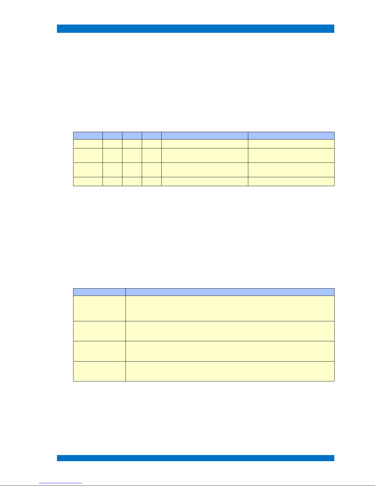
Pixel Errors
Following limited values which may not exceed are valid.
ISO 13406-2 Typ 1 Typ 2 Typ 3 max. Distance connected Defects
Class I 0 0 0
Class II 2 2 5 1 defect pixel within a circle of 5 mm
maximum 2 defective sub-pixel beside
each other
Class III 5 15 50 2 defect pixels within a circle of 5 mm
maximum 2 defective sub-pixel beside
each other
Class IV 50 150 500
Error-type #1 describes errors by a complete bright (white) pixel, error-type #2 describes errors by a
complete dark (black) pixel, error-type #3 describes errors by defective sub-pixels of the colors red,
green and blue, which are completely bright or dark.
A single LCD pixel is built by a set of three sub-pixels, one of red, green and blue.
Error class I contains highly selected panels with no pixel error anyway. Panels within this class are rare and very high priced. Panels from the error class II are the most common selection for high quality
industry applications. The error class III defines the mass production selection for IT applications. TFT
panels related to the error class IV are not useful for a LCD monitor at all.
Class of Usability
Next the standard ISO 13406-2 defines the classification of usability of LCD screens.
Usability Classification Description
Class 1 This permits several users to view the entire display area at the same time. This applies for intended
viewing distance (between 40 to 60 cm, depending on the size and resolution of the monitor) and for
a viewing angle within an 80° cone in front of the screen without any restriction of visual efficiency, in
such a way that brightness, contrast and color is maintained
Class 2 Permits a single user to view the entire area of the display. This applies for intended viewing distance
(between 40 to 60 cm, depending on the size and resolution of the monitor) from every position in
front of the screen, in such a way that brightness, contrast and color is maintained.
Class 3 Permits a single user to view the entire area of the display. This applies for intended viewing distance
(between 40 to 60 cm, depending on the size and resolution of the monitor) from one fixed position
in front of the screen, in such a way that brightness, contrast and color is maintained.
Class 4 Permits a single user to view the center area of the display. This applies for intended viewing
distance (between 40 to 60 cm, depending on the size and resolution of the monitor) from one fixed
position in front of the screen, in such a way that brightness, contrast and color is maintained.
All of the TAMUZ SPARROWHAWK series monitors comply with class 1.
Class of Reflections
The reflection characteristics of an LCD Screen are of particular importance in very bright ambient
conditions or in an environment with multiple light sources. The ISO standard provides for three quality classes.
© 02.07 TAMUZ - LCD Video Monitors LSM Digital Broadcast Monitor Page - 8 -

SPARROWHAWK series Models SPARROWHAWK
Reflection Classification Description
Class 1 General office conditions without special requirements as to workspace lighting.
Class 2 Appropriate for most office conditions, with few exceptions.
Class 3 Appropriate for office environments, with controlled luminance conditions.
All of TAMUZ SPARROWHAWK series monitors comply with class 1.
All of TAMUZ SPARROWHAWK series monitors are equipped with a anti-reflective anti-glare filter
made of glass.
Wide Screen Format
All the TAMUZ SPARROWHAWK series are LCD monitors equipped with wide screen active TFT displays, developed to display 16:9 wide screen videos with a full screen image without any loss.
Their native screen aspect ratio is 16:9 or similar, so real full screen 4:3 video sources fills the monitor
screen with black areas at left and right, if the monitor is switched to 4:3 mode.
Note: If you use the SPARROWHAWK series monitor in a real full screen mode for 16:9
sources, the aspect ratio of the displayed image is correct!
Some sources don't produce a real 16:9 signal.
The TAMUZ SPARROWHAWK series is able to handle different type of signals, see table below.
Format horizontal
Resolution
vertical
Resolution
Pixel Style Input Source Äquivalent
16 : 9 1920 1080 square DVI-D full wide screen - full resolution W-UXGA
16 : 9 1920 1080 square HD-SDI full wide screen - full resolution HDTV 1080 format
16 : 9 1280 720 square HD-SDI full wide screen - full resolution HDTV 720 format
4 : 3 720 576 rectangle SDI standard video – full resolution SD 625 format
16 : 9 720 576 rectangle SDI wide screen video – full resolution SD 625 format
4 : 3 720 480 rectangle SDI standard video – full resolution SD 525 format
16 : 9 720 480 rectangle SDI wide screen video – full resolution SD 525 format
Sampling the Video
TAMUZ develops special interfaces, labeled EAGLE and FALCON, to process the video to be displayed on a LCD Screen.
The EAGLE or FALCON interface operates within the SPARROWHAWK series is mainly a scaling
mode. This is necessary to do, because there is a difference between the incoming SD or HD video signal formats and the panel resolutions.
The pixel-to-pixel mode takes place, only when the native resolution of the TFT fits to the video resolution. Each incoming pixel information will be transferred to its corresponding geometrical position at
the display. This happens with computer signals from the DVI-D port and with High-Definition digital signals from the HD-SDI port too.
Most of the common SMPTE 274M and 296M HD formats are supported.
© 02.07 TAMUZ - LCD Video Monitors LSM Digital Broadcast Monitor Page - 9 -

General Safety Instructions SPARROWHAWK
General Safety Instructions
Limitation of the product
The LCD technology itself and some LCD panels built-in the TAMUZ SPARROWHAWK LSM 1xxW
series have limitations which the user have to understand and accept.
The user must accept that it is necessary
to avoid condensation of water within the SPARROWHAWK series. It may result in
improper operation or disconnection of electrodes.
not to exceed the absolute maximum rating value. (input voltage variation, environmental
temperature and so on) Otherwise the monitor may be damaged.
to avoid image sticking. If the monitor keeps displaying the same pattern for a long period
of time without any movement, the image may be „sticked“ to the screen. It is
recommended to use the „anti-sticking“ screen saver. See chapter Submenu Anti-Sticking
to handle the monitor carefully in order not to be stressed. The monitor is equipped with
sensitive glass plates, light bulbs and electronics.
to add ultra-violet ray filters for outdoor operation.
Duty of care of the user
The SPARROWHAWK LSM 1xxW series was designed and built under the harmonized norms to be
adhered as well as further technical specifications. It corresponds to the state of the art and ensures a
maximum amount of safety.
However, this safety can only be reached, if all safety measures are taken in the operational practice.
It is the duty of the SPARROWHAWK LSM 1xxW series user, to plan these measures and check
their explanation.
The user must guarantee that
the SPARROWHAWK series is only used as agreed (cf. chapter product specification)
the SPARROWHAWK series is operated only in faultless, working condition and
particularly the safety facilities are checked for their function efficiency regularly
the SPARROWHAWK series operator's manual always be placed in a complete and
legible condition for disposal
only sufficiently qualified and authorized staff operates, maintains and repairs the
SPARROWHAWK series
staff is instructed to meet work safety and environmental protection regulation and knows
the operator's manual as well as there particularly contained safety instructions
all appropriate safety and warning notes not being removed and remaining legible at the
SPARROWHAWK series
Constructive changes at the SPARROWHAWK series may be carried out only after written permission by the manufacturer!
Safety symbols
The following safety symbols are applied in this operator's manual. These symbols shall primarily draw
the attention of the reader to the text of the accompanying safety note.
This symbol points out that there are dangers for life and health
of persons.
© 02.07 TAMUZ - LCD Video Monitors LSM Digital Broadcast Monitor Page - 10 -

General Safety Instructions SPARROWHAWK
This symbol indicates information which contributes for a better
understanding of the function of the equipment.
This symbol points out that there are dangers for material and
environment or the equipment himself.
Warning about dangerous electrical voltages to or within the
equipment.
Basic Safety Instructions
The SPARROWHAWK series only may be used by persons who are trained, authorized and has
knowledge of the operator's manual.
Before every production, check the SPARROWHAWK series for visible damages and make sure that
it is operated in faultless condition! Report noticed deficiencies to the supervisor immediately or schedule to restore by qualified persons.
Service and Maintenance
Adhere to the specified inspection and maintenance intervals in the operator's manual!
Before maintenance and repair work it must be guaranteed that all parts of the
SPARROWHAWK series have cooled down on space temperature!
Smear-, cool- or cleaning-fluids, endangering the environment, must be disposed duly!
Repair work on the electrical power supply of the SPARROWHAWK series system must
be done by a trained electric qualified employee!
Damaged lines or cables have to be immediately replaced!
Released bolted joints must be checked for solid seat before putting into operation after maintenance
or repair work and it must be guaranteed, that removed system-unit cover parts or filters were re-installed!
Observe environmental protection prescriptions
The legal duties for waste avoidance and proper utilization for elimination must be adhered at all work
stations, also including the SPARROWHAWK.
During repair, installation and maintenance work, be aware of water endangering substances such as;
Lubricating greases and oil
Hydraulics oils
Coolant
solvent containing cleaning liquids
don't load the floor or reach into the sewage system!
Note: The valid environmental protection prescriptions must be observed.
These water endangering substances must be kept, transported, caught and disposed in suitable containers!
© 02.07 TAMUZ - LCD Video Monitors LSM Digital Broadcast Monitor Page - 11 -

General Safety Instructions SPARROWHAWK
Recycling
If SPARROWHAWK series monitor no longer operates or is un-repairable, please do not dispose the
monitor in the trash.
Please return the monitor to your local dealer or TAMUZ directly, we will grant the correct and suitable
recycling of the old monitor.
Note: Don't waste unused, old or broken monitors. Follow your local environmental protection
prescriptions.
Recognition of the copyrights
The user of the SPARROWHAWK series appreciates, that in the SPARROWHAWK series contains
software programs as well as this documentation is subject to the copyright laws as well as copyright
propriety and other protection rights and does not purchase this with the acquisition or the use of the
SPARROWHAWK series system by any time. The user obtains rather merely the right for the exclusive use of the SPARROWHAWK series.
In the SPARROWHAWK series contained software as well as the accompanying documentation may
not be changed, enlarged or adapted to other systems or translated into other languages, without written permission of the author. With the installation and use of the SPARROWHAWK series the user
recognizes these license and use conditions.
Note: The SPARROWHAWK series system contains copyright protected software and
documentation's.
© 02.07 TAMUZ - LCD Video Monitors LSM Digital Broadcast Monitor Page - 12 -

Guarantee agreement: SPARROWHAWK
Guarantee agreement:
In the SPARROWHAWK LSM 1xxW series system contains software and the instructions are left to
the user as they are. This means, the author of the software or the instructions doesn't assume any liability for the suitability of the software or the documentation to any special purpose. He particularly
isn't liable for damages or sequential damages which indirectly deliberately or unintentionally arise
f
rom the use of the SPARROWHAWK LSM 1xxW series or the documentation directly.
The SPARROWHAWK LSM 1xxW series system and the documentation can be changed and enlar-
ged without previous announcement at any time. Rights for updates free of charge does not apply.
Guarantee period
TAMUZ - LCD Video Monitors, the manufacturer of the SPARROWHAWK LSM 1xxW series grants a
guarantee period of 24 months on the faultless function of the system and its components.
Guarantee exceptions
Claims for defects shall not exist in cases of
natural wear and tear and damages, defects, reduced output, and changes of condition or
operation of our product due to extraneous cause (for example impact, blows, agitation,
water, fire), improper storage, treatment or erection, unusual climatic conditions, special
conditions at receipt or operational conditions at the location of use, or force majeure;
defects due to construction and material deficiencies, as far as the customer has specified
the construction or the material.
Image Sticking on the LCD-Panel, which is caused by permanent pictures as well as Gap
Mura on the LCD-Panel.
Guarantee Certification
Please, send in the full guarantee certification upon receipt of the product to the manufacturer or
suppliers within 21 working days. The manufacturer or supplier only then can grant possible rights to
claim under guarantee in full size and transmitting current information about software updates and indications for expansions or for the operation of the equipment to you.
Note: Only if the guarantee card of the SPARROWHAWK LSM 1xxW series monitor has
been returned intime to the manufacturer or supplier, rights to claim under guarantee can be
asserted against the manufacturer or supplier.
© 02.07 TAMUZ - LCD Video Monitors LSM Digital Broadcast Monitor Page - 13 -

Warranty Card SPARROWHAWK
Warranty Card
To come in the position to reclaim your warranty rights, send in this warranty card within 21 days to
the manufacturer (TAMUZ - LCD Video Monitors, Germany) or your local dealer. Check the web site
www tamuz.tv, www tamuz.de or www tamuz.us for the correct address.
Garantie Registrierungskarte - Warranty Registration Card
Model:
TAMUZ LSM
Type:
Seriennummer: Serial Number:
Dieses Gerät wurde gekauft bei: - The Unit was purchased from:
Händler:
Ort.
Land:
Dealer:
City:
Country:
Verkaufsdatum: Purchase Date:
Dieses Gerät wurde gekauft von: - The Unit was purchased by:
Kunde: Customer:
Ansprechpartner: Contact Person:
Firma: Company:
Strasse: Street:
PLZ: Zip Code:
Ort: City:
Land: Country:
Telefon: Phone:
Telefax: Fax:
Email: Email:
Dieses Gerät wird eingesetzt im: - This Unit will be used at:
Regieraum: Control Room:
Schaltraum: Distribution:
Studio: Studio:
Ü-Wagen: OB-Truck:
Kopieranlage: VTR-Dubbing:
Schnittplatz: Editing:
Sprecher-Raum: Off-Room:
Andere: Other:
Unser Bestreben ist es, unsere Produkte kundengerecht zu entwickeln und fertigen. Wir sind Ihnen dankbar, wenn Sie sich
Zeit für Anregungen oder Kommentare nehmen:
Our mutual interest is, to design and manufacture practical products. We appreciate you taking the time to note your
information and comments you may have.
© 02.07 TAMUZ - LCD Video Monitors LSM Digital Broadcast Monitor Page - 14 -

Transport of the equipment SPARROWHAWK
Transport of the equipment
Transportation
The SPARROWHAWK LSM 1xxW series is a sensitive electronic product and should be transported
with all caution. Throwing the equipment or hard pushes during the transport must be avoided.
Weight
The SPARROWHAWK LSM 1xxW series weights inclusive of the accessories and his packing more
then 10 kg and should be carried under consideration of the accident prevention measures or transported with help of corresponding aids therefore by two persons.
Note: Observe the accident prevention prescriptions at the transport of the
SPARROWHAWK LSM 1xxW series to the avoidance of persons and damages to
property.
Packing
The SPARROWHAWK LSM 1xxW series is delivered in a special transport carton. It recommends it-
self to keep this carton and the accompanying packaging. So in the case of a later necessary transport and dispatch the equipment can be packed and protect against damages as delivered to you.
Return dispatch
At a return dispatch without original packing to the supplier or manufacturer the liability is excluded.
Don't forget to ask for a RMA (return material authorization) number before you send any material
back to the manufacturer. Check for a RMA the web-site www.tamuz.tv, www.tamuz.de or www.tamuz.us.
Damages in transit
Check the contents of the received transport carton with the delivery note or the invoice on completeness and inform your supplier if you have missing parts upon receipt of the product. Please contact
within 5 working days. If you receive a delivery on which the transport carton or the contents is damaged, proceed after the known guidelines of the cargo shipper, (which as a rule is enclosed with the
delivering papers). Perhaps stricter terms must be taken into account.
Note: Check before using the SPARROWHAWK LSM 1xxW series whether damages in
transit have been happened and arrange a repair of these damages if necessary.
© 02.07 TAMUZ - LCD Video Monitors LSM Digital Broadcast Monitor Page - 15 -

Conformity Declaration SPARROWHAWK
Conformity Declaration
to EMV/EMC guideline (89/336/EC)
to low-voltage guideline (73/23/EC chapter 10)
The manufacturer:
TAMUZ - LCD Video Monitors
Tiedenkamp 16
D-24558 Henstedt-Ulzburg
declares hereby, that the product:
Product name: LCD Video Monitor
Model number: SPARROWHAWK LSM 1xxW series
Year of construction: 2005
corresponds to the regulations of the guidelines described above:
The following harmonized norms were used:
EN 55011 ISM Equipment, Group 1, Class A
EN 55022 Conducted Emissions, Class B
EN 50081-2 Generic standard interference transmission, industry area
EN 50082-2 Generic standard interference immunity, industry area
prEN55103-1 EMV product family norm for Audio-, Video and audio-visual facilities
as well as for studio light control facilities for the professional usage,
-Part 1: Limiting values and measurement procedure for disturbing
emissions
prEN55103-2 EMV product family norm for Audio-, Video and audio-visual facilities
as well as for studio light control facilities for the professional usage,
-Part 2: Requirements on the interference immunity
EN 61000-3-2 Power Factor Harmonic Correction
EN 61000-3-3 Flicker & Voltage Fluctuation Limits
EN 61000-4-2 Electrostatic Discharge Immunity
EN 61000-4-3 Radiated Electromagnetic Fields
EN 61000-4-4 Fast Transients-Burst Immunity
EN 61000-4-5 Input Surge Immunity
EM 61000-4-6 Conducted RFI
EN 61000-4-11 Voltage Dips
The following national or international norms (or parts/clauses from this) and specifications were used:
DIN EN 6099 Verbindungsmaterial für Niederspannungsstromkreise für Haushalt
und ähnliche Zwecke; Teil 1: Allgemeine Anforderungen
IEC 127-6 Geräteschutzsicherungen
Henstedt-Ulzburg, 08.10.2005
CEO / President
© 02.07 TAMUZ - LCD Video Monitors LSM Digital Broadcast Monitor Page - 16 -

Technical Data SPARROWHAWK
Technical Data
System Hardware SPARROWHAWK series
The hardware of the Video Monitor consists of the following components which are installed in an elegant and emission shielded full metal system-unit cover of high quality:
Item LSM 124W LSM 127W LSM 132W LSM 137W LSM 142W
System Frame LSM 124W LSM 127W LSM 132W LSM 137W LSM 142W
Dimensions 550 x 375 x 95 642 x 338 x 110 765 x 460 x 130 890 x 530 x 130 1015 x 611 x 130
Weight 10 kg 11 kg 17 kg 35 kg 39 kg
Mounting VESA 100 VESA 100 VESA 100 VESA 100 VESA 100
Display Size 24“ active matrix 27“ active matrix 32“W active matrix 37“W active matrix 42“ active matrix
Display Type
LTA240M2
*
1
LTA270M1 *
1
LTA320M1 *
1
V370H01 *
1
V420H01 *
1
Display Technology amorphous silicon amorphous silicon amorphous silicon amorphous silicon amorphous silicon
Resolution 1920 x 1200 1920 x 1200 1366 x 768 1920 x 1080 1920 x 1080
Dot Format RGB, square RGB, square RGB, square RGB, square RGB, square
Display Aspect Ratio 16 : 10 16 : 10 16 : 9 16 : 9 16 : 9
Color Format 24 bit full color 24 bit full color 24 bit full color 24 bit full color 24 bit full color
Luminance >300 cd/m
2
>400 cd/m
2
>400 cd/m
2
>700 cd/m
2
>400 cd/m
2
Contrast >600 : 1 >600 : 1 >600 : 1 >800 : 1 >600 : 1
Viewing Angle ±85° H, ±85° V ±85° H, ±85° V ±85° H, ±85° V ±85° H, ±85° V ±85° H, ±85° V
Viewing Direction 06:00 h 06:00 h 06:00 h 06:00 h 06:00 h
Display Classification ISO 13406-2 ISO 13406-2 ISO 13406-2 ISO 13406-2 ISO 13406-2
Pixel Error Class class 2 class 2 class 2 class 2 class 2
*1= or similar alternative, *2= optional feature
Item LSM 147W LSM 152W LSM 157W LSM 165W LSM 182W
System Frame LSM 147W LSM 152W LSM 157W LSM 165W LSM 182W
Dimension 1140 x 692 x 130 1252 x 748 x 140 1344 x 782 x 140 1622 x 922 x 150 1972 x 1180 x 150
Weight 40 kg 46 kg 49 kg 61 kg 77 kg
Mounting VESA 100/200 VESA 100/200 VESA 100/200 VESA 100/200 VESA 100/200
Display Size 47“ active matrix 52“ active matrix 57“W active matrix 65“W active matrix 82“ active matrix
Display Type
V470H02
*
1
V520H01 *
1
LTI570HS *
1
LK645D3 *
1
LTI820M01 *
1
Display Technology amorphous silicon amorphous silicon amorphous silicon amorphous silicon amorphous silicon
Resolution 1600 x 1200 640 x 480 1366 x 768 1920 x 1200 1920 x 1080
Dot Format RGB, square RGB, square RGB, square RGB, square RGB, square
Display Aspect Ratio 16 : 9 16 : 9 16 : 9 16 : 9 16 : 9
Color Format 24 bit full color 24 bit full color 24 bit full color 24 bit full color 24 bit full color
Luminance >400 cd/m
2
>400 cd/m
2
>400 cd/m
2
>400 cd/m
2
>600 cd/m
2
Contrast >700 : 1 >700 : 1 >1000 : 1 >1000 : 1 >1200 : 1
Viewing Angle ±85° H, ±85° V ±85° H, ±85° V ±85° H, ±85° V ±85° H, ±85° V ±85° H, ±85° V
Viewing Direction 06:00 h 06:00 h 06:00 h 06:00 h 06:00 h
Display Classification ISO 13406-2 ISO 13406-2 ISO 13406-2 ISO 13406-2 ISO 13406-2
Pixel Error Class class 2 class 2 class 2 class 2 class 2
© 02.07 TAMUZ - LCD Video Monitors LSM Digital Broadcast Monitor Page - 17 -

Technical Data SPARROWHAWK
System Features SPARROWHAWK series
The video monitor SPARROWHAWK series is designed and equipped for the following requests,
tasks and applications :
Item LSM 124W LSM 127W LSM 132W LSM 137W LSM 142W LSM 147W LSM 152W LSM 157W LSM 165W LSM 182W
Application Digital Broadcast Control Monitor, MultiSync Computer Monitor
Graphic Format WUXGA WUXGA WXGA HDTV HDTV HDTV HDTV HDTV HDTV HDTV
Graphic I/O SubD-HD15
Video Format SD or SD/HD-SDI, auto detection
Video Level 800 mVpp ±10% digital
Video I/O BNC 75 Ohm terminated
Signal Format SD 1x SDI
Signal Format HD 1x SD/HD-SDI
analog Video Format analog composite, PAL, NTSC, SECAM *
2
analog Video Level 1 Vpp
analog Video I/O BNC 75 Ohm active looped or terminated *
2
Power Requirements
DC 24 V ±20% @
XLR-5M
AC 100 - 240 V ±15% @ IEC320 3pin
Power Consumption
68 90 180 200 230 250 280 320 680 710
Line Voltage 85 – 264 V AC, 50-60 Hz, short circuit proofed
Mains Input I/O IEC320 3pin
Operation
Temperature
0°C to +50°C at max. 80% humidity
Storage Temperature -30°C to +60°C at max. 95% humidity
*1= or similar alternative, *2= optional feature
© 02.07 TAMUZ - LCD Video Monitors LSM Digital Broadcast Monitor Page - 18 -

Installation SPARROWHAWK
Installation
First putting into Operation
The video monitor SPARROWHAWK series has an especially designed system-unit cover. It contains all components of the monitor and it is installed operational. Modification is not usually required
by the user.
Take the monitor SPARROWHAWK from the packing and check it for possible damages in transit.
Please, Indications of damage, please refer to transportation documents.
Mounting in 19“ Racks
The smaller sized SPARROWHAWK series (LSM 124W and LSM 127W) are prepared for mounting
in standard 19“ or 23“ racks.
Therefore mount the optional brackets on the left and right side of the monitor.
The bigger sized SPARROWHAWK series is not prepared for mounting in a standard 19“ rack. These monitors are recommended for VESA mounting at walls, ceilings or customized systems.
Note: Use the optional brackets to mount the monitor in a 19“ rack only.
Check the packaging for the optional brackets and keep them in a safe place for future usage.
Mounting at VESA systems
Starting with the type LSM 124W from the SPARROWHAWK series the monitors are equipped with a
set of VESA compatible treads at the rear.
On the rear side are treads for mounting some VESA 75/100/200 standard systems.
Ventilation
Depending on the type of installation, the equipment is a self ventilated device which has air ventilation
openings at the rear. Regarding of the size, the smaller models have no integrated fans. The larger
models, starting with the LSM 132W, are equipped with a slow running fan producing a continuous
stream of cooling air.
Note: When required check the chassis for faultiness and clean them regularly.
© 02.07 TAMUZ - LCD Video Monitors LSM Digital Broadcast Monitor Page - 19 -

Installation SPARROWHAWK
Cleaning
Remember the LCD screen itself is a sensitive device, Avoid scratching it. This device may be cleaned
with usual household glass cleaning fluids only. Avoid scrapers and rub on screen surface.
Note: When required check the device for faultiness regularly and clean it with a gentle glass
cleaner and soft cotton cloths. No acids or solvent may be used for cleaning.
External Control Units
External control units aren't necessary for the normal use of the monitor.
Note:ThemodelLSM xxxW is a digital display and didn't need any external control. It always
displays the incoming input signal at it best.
In case of special modes or for service an optional IR remote controller (EAGLE WHISTLE)is
available and necessary to obtain access to the OSD menu. This feature is available for all SPAR-
ROWHAWK LSM 1xxWW monitors as an option.
Please ask your service department or dealer if necessary.
© 02.07 TAMUZ - LCD Video Monitors LSM Digital Broadcast Monitor Page - 20 -

Installation SPARROWHAWK
Switching the Monitor on
Guarantee the connection with the external mains power at the rear ICE connector indicated as AC input at the adapted power supply.
Prove if the DC plug is connected to the DC inlet.
For switching the display of the monitor SPARROWHAWK LSM 1xxW series on: press the accompanying switch POWER at the rear.
The monitor starts test routines automatically and then represents the video on display.
The LED in the POWER switch illuminates, additionally the LEDs at the input selection illuminates in
the last selected setup; here SDI input A.
Note: The video monitor SPARROWHAWK LSM 1xxW series is equipped with an internal
universal power supply to work under any power circumstances.
During the test routines the TAMUZ logo appears shortly on the screen after clearing the memory.
Thereafter the monitor shows the signal from the selected input source (refer to the manual chapter
Operation / Input Switch). If the source at this input port doesn't feed a signal into the monitor, an error
message appears on the screen.
Check the cable connections or the feeding source itself.
© 02.07 TAMUZ - LCD Video Monitors LSM Digital Broadcast Monitor Page - 21 -

Installation SPARROWHAWK
Power Save Mode
After a period of waiting (to refer the period length see chapter OSD menu / DPMS) for an incoming signal the monitor automatically switches to the POWER SAVE mode in two steps.
Suspend Mode
The first step of saving power is the SUSPEND mode. After a default five seconds period of waiting for
an incoming signal, the micro processor switches the backlight down to a minimum brightness value.
The screen becomes darker.
Power Down Mode
The second step of saving power is the POWER DOWN mode. Waiting for another fifteen seconds
(default period), the micro processor switches the backlight off and stops processing for video signals. The screen becomes black and the power indicator LED at the front is still illuminated.
Power Save Wake Up
When the POWER SAVE mode is activated, a wake up will happen automatically when the internal micro processor recognize a video signal at the selected input.
The monitor comes back on and the incoming signal will be shown on the screen.
© 02.07 TAMUZ - LCD Video Monitors LSM Digital Broadcast Monitor Page - 22 -

Connections of the Monitor SPARROWHAWK
Connections of the Monitor
The Monitor Screen
The video monitor SPARROWHAWK LSM 1xxW series contains a single, individual working, screen.
The following instructions and steps apply to the screen.
All input connectors are placed at the rear.
Depending on the model, connections various. See above model SPARROWHAWK LSM 1xxW HD.
Model SPARROWHAWK LSM 1xxW is equipped with graphic inputs and remote ports only.
Model SPARROWHAWK LSM 1xxW is equipped with DVI input only.
© 02.07 TAMUZ - LCD Video Monitors LSM Digital Broadcast Monitor Page - 23 -

Connections of the Monitor SPARROWHAWK
DC Voltage
The DC voltage to operate the SPARROWHAWK LSM 124W / LSM 127W video monitors will be
supplied by an external Power Supply. The connection happens with a XLR 5pin port at the rear.
The pin-out of the XLR5M port is shown in following table:
Pin Function
1Ground
2NC
3NC
4NC
5 + 12 V DC
Power Supply
Interconnect the mains output using a reliable cord with the IEC port of the external Power Supply.
The pin-out of the IEC port is shown in following table:
Pin Function
1 (N) Neutral
2 (P) Phase
3 (GND) Ground
AC Voltage
The voltage to operate the SPARROWHAWK LSM 132W ./. LSM 182W video monitors will be supplied by an internal Power Supply. Interconnect the mains output using a reliable cord with the IEC port
of the internal Power Supply.
The pin-out of the IEC port is shown in following table:
Pin Function
1 (N) Neutral
2 (P) Phase
3 (GND) Ground
Note: Warning about dangerous electrical voltages to or within the equipment. Take care to
use the correct power cord depending to your local electricity safety system.
© 02.07 TAMUZ - LCD Video Monitors LSM Digital Broadcast Monitor Page - 24 -

Connections of the Monitor SPARROWHAWK
Video Inputs at Version LSM 1xxW
The version LSM 1xxW of the SPARROWHAWK series was designed for digital graphic signals (DVI)
and VGA graphic signals in any common or uncommon resolution. Optionally analog composite video
signals for the formats PAL, SECAM or NTSC can be equipped.
Connect your video source using standard 75 Ohm BNC cables to the input ports at the rear of the
monitor. The inputs are internally 75 Ohm terminated. There is no need for an external standard 75
ohm terminating resistor.
DVI Inputs
Depending on the version of the device the allocation of the ports varies. The respectively DVI jack is
described as input.
The allocation of the ports is shown in following table:
Model / Interface
Type
Series Format Input 1 Input 2 Input 3 Input 4 Input 5 Input 6
LSM 1xxW SPARROWHAWK Graphics CCVS CCVS DVI --- --- VGA
Connect your DVI graphic source using standard DVI-D cables to the input ports at the rear of the monitor.
This port accepts all common or uncommon analog graphic signals regarding his MultiFormat MultiSync capability. For supported formats check the chapter VGA Formats in the service section.
Optional Input CCVS
As an option of the LSM 1xxW of the SPARROWHAWK series a pair of BNC ports is defined as
CCVS input, left as input 1 and right as input 2. This option has been equipped when ordered.
Signal Format
The video monitors LSM 1xxW of the SPARROWHAWK series are designed as a MultiFormat and
MultiSync monitors to be used with signals in the format PAL/SECAM 625/50 or NTSC 525/60, regardless if analog or digital version.
As standard the integrated signal processor recognizes the video format automatically and adapts itself to this correspondingly. The picture aspect ratios should be adapted by adjusting H and V size to
the video screen size if necessary (service available under service conditions only).
Usually the wide screen monitor type shows a full screen picture every time feeding 16:9 images. In
case of a 4:3 aspect ratio image, select the 4:3 mode using the OSD menu.
© 02.07 TAMUZ - LCD Video Monitors LSM Digital Broadcast Monitor Page - 25 -

Connections of the Monitor SPARROWHAWK
Video Inputs at Version LSM 1xxW HD
The version LSM 1xxW HD of the SPARROWHAWK series was designed for serial digital component
(SDI) signals and serial digital High-Definition (HD-SDI) signals in the formats 1080i, 1035i, 24/25sf
and 720p, or VGA graphic signals.
Connect your video source using standard 75 Ohm BNC cables to the input ports at the rear of the
monitor. The inputs are internally 75 Ohm terminated. There is no need for an external standard 75
ohm terminating resistor. Connect your VGA graphic source using standard Sub-HD15 cables to the
input ports at the rear of the monitor.
DVI Inputs
Depending on the version of the device the allocation of the ports varies. The respectively DVI jack is
described as input.
The allocation of the ports is shown in following table:
Model / Interface
Type
Name Format Input 1 Input 2 Input 3 Input 4 Input 5 Input 6
LSM 1xxW HD SPARROWHAWK HD Graphics / HD CCVS CCVS DVI HDSDI HDSDI VGA
Connect your DVI graphic source using standard DVI-D cables to the input ports at the rear of the monitor.
This port accepts all common or uncommon analog graphic signals regarding his MultiFormat MultiSync capability. For supported formats check the chapter VGA Formats in the service section.
Optional Input CCVS
As an option of the LSM 1xxW HD of the SPARROWHAWK series a pair of BNC ports is defined as
CCVS input, left as input 1 and right as input 2. This option has been equipped when ordered.
Signal Format
The video monitor SPARROWHAWK LSM 1xxW HD series are designed as a MultiFormat and MultiSync monitor to be used with signals in the format SD and HD, regardless of the format.
As standard the integrated signal processor recognizes the video format automatically and adapts itself to this correspondingly. The picture aspect ratios should be adapted by adjusting H and V size to
the video screen size if necessary (service available under service conditions only).
Usually the wide screen monitor type shows a full screen picture every time feeding 16:9 images. In
case of a 4:3 aspect ratio image, select the 4:3 mode using the OSD menu step GEOMETRY.
For faster operation the button 16:9 / 4:3 opens the menu step directly.
© 02.07 TAMUZ - LCD Video Monitors LSM Digital Broadcast Monitor Page - 26 -

Connections of the Monitor SPARROWHAWK
HDTV Input
At the LSM 1xxW HD of the SPARROWHAWK series the digital input ports are configured as HDTV
inputs for 4:2:2 1.5 Gbit/s signals. They did not accept DualLink 4.2:2 signals.
S
elect the HDSDI source in the INPUT menu to show the HDTV signal on screen.
Most of the common HDTV formats are supported by the internal HD interface, see table below. The
input signal format for HD is is the common SMPTE 274M HD-SDI stream with 1,5 Gbit/s data rate.
The signal will be detected automatically.
Format Samples per line Active lines Frame rate Scanning format supported
2kp @ 24 2048 1080 24 Progressive YES
2kp @ 23,98 2048 1080 23.98 Progressive YES
2ksf @ 24 2048 1080 24 Progressive segmented frames YES
2ksf @ 23,98 2048 1080 23.98 Progressive segmented frames YES
1080p@60 1920 1080 60 Progressive YES
1080p@59,94 1920 1080 59.94 Progressive YES
1080p@50 1920 1080 50 Progressive YES
1080i@60 1920 1080 60 2:1 interlace YES
1080i@59,94 1920 1080 59.94 2:1 interlace YES
1080i@50 1920 1080 50 2:1 interlace YES
1080p@30 1920 1080 30 Progressiv YES
1080p@29,97 1920 1080 29.97 Progressiv YES
1080p@25 1920 1080 25 Progressiv YES
1080p@24 1920 1080 24 Progressiv YES
1080p@23,98 1920 1080 23.98 Progressiv YES
1080p@30sf 1920 1080 30 Progressive segmented frames YES
1080p@29,97sf 1920 1080 29.97 Progressive segmented frames YES
1080p@25sf 1920 1080 25 Progressive segmented frames YES
1080p@24sf 1920 1080 24 Progressive segmented frames YES
1080p@23,98sf 1920 1080 23.98 Progressive segmented frames YES
720p@60 1280 720 60 Progressive YES
720p@59,94 1280 720 59.94 Progressive YES
720p@50 1280 720 50 Progressive YES
720p@30 1280 720 30 Progressive YES
720p@29,97 1280 720 29.97 Progressive YES
720p@25 1280 720 25 Progressive YES
720p@24 1280 720 24 Progressive YES
720p@23,98 1280 720 23.98 Progressive YES
576i@50 720 576 50 2:1 interlace YES
480i@60 720 480 59.94 2:1 interlace YES
The list of currently supported formats may be changed without notice.
© 02.07 TAMUZ - LCD Video Monitors LSM Digital Broadcast Monitor Page - 27 -

Connections of the Monitor SPARROWHAWK
VGA Input
As standard the LSM 1xxW HD of the SPARROWHAWK series is equipped with an analog graphic signal port, known as VGA port.
Connect your VGA graphic source using standard Sub-HD15 cables to the input ports at the rear of
the monitor.
This port accepts all common or uncommon analog graphic signals regarding his MultiFormat MultiSync capability. For supported formats check the chapter VGA Formats in the service section.
Ethernet IP Interface
As added option TAMUZ SPARROWHAWK series models may have an Ethernet IP port built-in at
the rear. SPARROWHAWK series monitors equipped with this IP addressable interface port allows
to communicates via a PC network, see MRC software.
The pin-out of the Ethernet RJ45 port is shown in following table:
The image above shows the RJ45 port. There are two standards used for Ethernet cabling, TIA-568A
and TIA-568B. Both are usable for a network to control the TAMUZ monitors.
Pin Function Color Code 568A Color Code 568B
1 Clear to send
2 Date send ready
3 Receive Data
4 Ground
5 Ground
6 Transmit Data
7 Data Termina Ready
8 Request to send
The IP port is standard at all SPARROWHAWK LSM 1xxW series monitors.
© 02.07 TAMUZ - LCD Video Monitors LSM Digital Broadcast Monitor Page - 28 -

Connections of the Monitor SPARROWHAWK
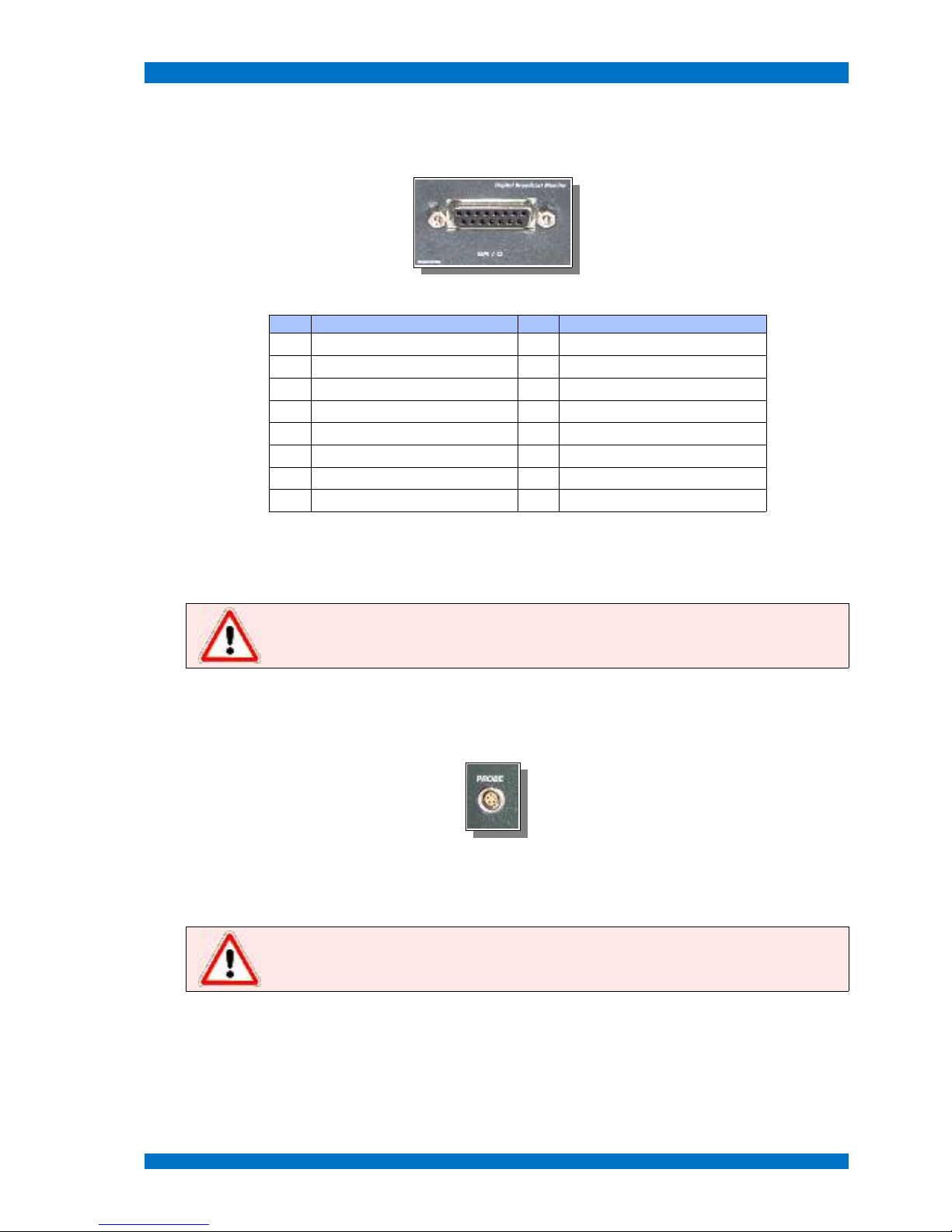
GPI/O Interface
For some special application a so-called GPI/O interface is helpful to control the monitor by external
events or get an information from or to external devices, like tally. Built-in at all SPARROWHAWK
LSM 1xxW series monitors.
The pin-out of the GPI/O port is shown in following table:
Pin Function Pin Function
1 GPI Tally Green, closed contact + 9 GPO Input SDI 1 active, +5 V
2 GPI Tally Red, closed contact + 10 Ground (GND)
3 GPI 16:9 / 4:3, closed contact + 11 Not Connected
4 GPI Input SDI 1, closed contact + 12 Not Connected
5 GPI Input SDI 2, closed contact + 13 Not Connected
6 GPI Input SDI 3, closed contact + 14 Not Connected
7 GPO Input SDI 1 active, +5 V 15 Not Connected
8 GPO Input SDI 2 active, +5 V
The GPI/O feature is standard at all SPARROWHAWK LSM 1xxW series monitors.
© 02.07 TAMUZ - LCD Video Monitors LSM Digital Broadcast Monitor Page - 29 -
Connections of the Monitor SPARROWHAWK
Service Interface
For some special application a so-called service interface is helpful to control or maintain the monitor
firmware by external devices, like a PC system.
This service interface is built-in the GPI/O port. The pin-out is shown in following table:
Pin Function Pin Function
1 GPI Tally Green, closed contact + 9 GPO Input SDI 1 active, +5 V
2 GPI Tally Red, closed contact + 10 Ground (GND)
3 GPI 16:9 / 4:3, closed contact + 11 Not Connected
4 GPI Input SDI 1, closed contact + 12 Not Connected
5 GPI Input SDI 2, closed contact + 13 RS 232 +
6 GPI Input SDI 3, closed contact + 14 RS 232 -
7 GPO Input SDI 1 active, +5 V 15 Ground
8 GPO Input SDI 2 active, +5 V
This port is available for the SPARROWHAWK LSM 1xxW series monitor (factory built-in at order).
This service interface can be used by service technicians to update the firmware. A special adapter
cable is necessary to connect to a PC RS232.
Note: Do not connect other equipment then the recommended RS232 adapter to this port.
The monitor and the connected device may become destroyed.
Probe Interface
All TAMUZ SPARROWHAWK series models have a probe port built-in at the front for alignment
applications. This port communicates with a color probe, like the TAMUZ AAC probe PM5639-T.
This port is standard at the SPARROWHAWK LSM 1xxW series monitors.
This service interface can be used by service technicians to align the monitor in colormetry and brightness.
Note: Do not connect other equipment then the recommended color analyzer probe to this
port. The monitor and the connected device may become destroyed.
© 02.07 TAMUZ - LCD Video Monitors LSM Digital Broadcast Monitor Page - 30 -

Operation SPARROWHAWK
Operation
The operation for all models in the SPARROWHAWK series is easy and intuitive to operate. The
main features are controlled by OSD menu. Individual setups or service features are available with the
optional IR-remote EAGLE WHISTLE.
Hereafter the manual operation for each model of the SPARROWHAWK series.
Operation Elements at the SPARROWHAWK series
There are no buttons, switches or adjustment controls at the front or rear at the monitor SPARROWHAWK LSM 1xxW.
POWER Switch
Use the switch POWER to put the SPARROWHAWK monitor into operation.
The power LED at the front indicates DC POWER ON and that the device is ready to be used.
Operation Buttons
There are no operational buttons at the front of the monitor. To operate and control the model SPARROWHAWK LSM 1xxW HD use the optional IR-remote. Button MENU (Speaker symbol) on the IR-re-
mote opens the OSD menu to select features or adjust the screen.
To navigate the menu use the UP and DOWN buttons, to select or activate a menu step use the
PLUS button. To adjust a value use the PLUS and MINUS button. To close the menu use the MENU
button.
Note: The SPARROWHAWK series is equipped with an IR remote control receiver. Therefore
use the recommended EAGLE Whistle remote controller.
© 02.07 TAMUZ - LCD Video Monitors LSM Digital Broadcast Monitor Page - 31 -

Operation SPARROWHAWK
Aspect Ratio Switch
Corresponding to the operation keys at a normal monitor use the IR-remote keys to operate the
SPARROWHAWK series monitors. Using the button UP when the main menu is not active, you may
toggle between the 16:9 wide screen and 4:3 mode of the SPARROWHAWK series monitors.
If the button 16:9 / 4:3 is pushed once, the monitors aspect ratio can be select between the 16:9 or
4:3 mode (see image below). The aspect ratio will be set to the corresponding values.
wide screen monitor in 16:9 mode, 720p signal at input standard monitor in 16:9 mode, 720p signal at input
wide screen monitor in full screen mode, 720p signal at input standard monitor in full screen mode, 720p signal at input
wide screen monitor in 4:3 mode, 720p signal at input standard monitor in 4:3 mode, 720p signal at input
© 02.07 TAMUZ - LCD Video Monitors LSM Digital Broadcast Monitor Page - 32 -

Operation SPARROWHAWK
wide screen monitor in 16:9 mode, 1080i signal at input standard monitor in 16:9 mode, 1080i signal at input
wide screen monitor in 1:1 mode, 1080i signal at input standard monitor in 1:1 mode, 1080i signal at input
wide screen monitor in 4:3 mode, 576i signal at input standard monitor in 4:3 mode, 576i signal at input
wide screen monitor in 16:9 mode, 576i signal at input standard monitor in 16:9 mode, 576i signal at input
© 02.07 TAMUZ - LCD Video Monitors LSM Digital Broadcast Monitor Page - 33 -

Operation SPARROWHAWK
wide screen monitor in 1:1 mode, 576i signal at input standard monitor in 1:1 mode, 576i signal at input
Anamorphic signals will be shown in the correct aspect ratio. Under 16:9 conditions standard 4:3 signals are shown in a horizontal stretched mode.
As default the active video area will be shown. The interface of the monitor SPARROWHAWK series
is capable to show the full video signal, in case of PAL formats up to 625 TV lines or in case of NTSC
formats up to 525 TV lines. Therefore you must adjust the setup for scanning TV lines in the menu
step GEOMETRY - SETTINGS - INPUT - LINES. The aspect ratio in a suitable way must corrected is after this.
Note: The 16:9 and 4:3 aspect ratio formats are selectable as default. If another aspect ratio
or anamorphic conversion is necessary, refer the service section of this manual to adjust your
individual setup.
Size Switch
Corresponding to the operation keys at a normal monitor use the IR-remote keys to operate the
SPARROWHAWK series monitors. Using the button DOWN when the main menu is not active, you
may toggle between different size modes of the SPARROWHAWK series monitors.
If the SIZE button is pushed once, the displayed size of the image can be selected between the UN-
DERSCAN – NORMAL – OVERSCAN - ZOOM mode (see image below). The aspect ratio will be set to
the corresponding values.
standard monitor in NORMAL mode, 576i signal at input standard monitor in UNDERSCAN mode, 576i signal at input
© 02.07 TAMUZ - LCD Video Monitors LSM Digital Broadcast Monitor Page - 34 -

Operation SPARROWHAWK
standard monitor in OVERSCAN mode, 576i signal at input standard monitor in ZOOM mode, 576i signal at input
The interface of the monitor SPARROWHAWK series is capable to adjust the displayed portion of
the video signal, in case of PAL formats up to 625 TV lines or in case of NTSC formats up to 525 TV lines or in case of 720p formats up to TV lines or in case of 1080i/p formats up to 1150 TV lines.
In NORMAL mode the full active area will be displayed.
In UNDERSCAN mode the total video signal, even the sync area, will be displayed.
In OVERSCAN mode the video will be cropped to 95% of the active area.
In ZOOM mode the video will be stretched or squeezed to an individual size. See ZOOM setup menu
for selected values. Default is zoom factor 2.00.
Note: In UNDERSCAN mode even the sync area will be displayed. This makes a H/V shift or
delay mode obsolete.
R/G/B Switch
Corresponding to the operation keys at a normal monitor use the IR-remote keys to operate the
SPARROWHAWK series monitors. Using the button DOWN when the main menu is not active, you
may toggle between the single color modes of the SPARROWHAWK series monitors.
If the PLUS button is pushed once, the displayed color of the image can be selected between the
NORMAL – RED – GREEN - BLUE mode (see image below).
standard monitor in NORMAL color mode, 576i signal at input standard monitor in RED color mode, 576i signal at input
© 02.07 TAMUZ - LCD Video Monitors LSM Digital Broadcast Monitor Page - 35 -

Operation SPARROWHAWK
standard monitor in GREEN color mode, 576i signal at input standard monitor in BLUE color mode, 576i signal at input
Using the R/G/B switch of the monitor SPARROWHAWK series the single color channels will be displayed separately. This helps to adjust contrast and brightness.
In NORMAL mode the image will be displayed in full color.
In RED mode the image will be displayed in red color only.
In GREEN mode the image will be displayed in green color only.
In BLUE mode the image will be displayed in blue color only.
Note: Only when the NORMAL mode is selected the image will be displayed in full color.
TALLY Indicator
The monitor SPARROWHAWK LSM 1xxW isn't equipped with a tally light.
If tally function is needed, ask your dealer for modification or support.
© 02.07 TAMUZ - LCD Video Monitors LSM Digital Broadcast Monitor Page - 36 -

Operation SPARROWHAWK
Option IR-Remote Controller
For individual setups or service purposes an optional IR remote controller (EAGLE WHISTLE)is
available.
The new model of the remote controller looks a little different.
The user may navigate the OSD menu with the keys on the controller. Open the OSD menu with the
key MENU. (the key with the speaker symbol at the new style remote) Toggle up or down in the menu
with the keys P+ and P-. Open a menu step or adjust a value with the keys V+ and V-.
Any key stroke will quit by the integrated LED.
Using the key POWER the monitor will activate the Power Save Mode.
© 02.07 TAMUZ - LCD Video Monitors LSM Digital Broadcast Monitor Page - 37 -

OSD Menu Operation SPARROWHAWK
OSD Menu Operation
For individual setups or service purposes the SPARROWHAWK LSM 1xxW series contains an OSD
menu. To get access to the menu you need to push the MENU button or to have the optional IR remote controller (EAGLE WHISTLE).
The user may navigate the OSD menu with the keys on the controller. Open the OSD menu with the
key MENU. Toggle the menu up or down using the UP (P+)andDOWN (P-) keys. Open a menu step
or adjust a value with the PLUS (V+) and MINUS (V-) keys.
OSD Menu
There are two important menus to operate or configure the SPARROWHAWK LSM 1xxW series interface. The MAIN MENU and the SYSTEM MENU.
The MAIN MENU contains all relevant items to operate the SPARROWHAWK LSM 1xxW series moni-
tor.
The SYSTEM MENU contains all relevant items to configure the SPARROWHAWK LSM 1xxW series
monitor.
© 02.07 TAMUZ - LCD Video Monitors LSM Digital Broadcast Monitor Page - 38 -

Main Menu SPARROWHAWK
Main Menu
Press the MENU key (Speaker symbol) at the IR-remote controller once to open the OSD menu. The
MAIN MENU appears on screen.
With most of the OSD menu steps a help window opens and describes the selected menu step. Use
the UP and DOWN keys (P+ and P- at the EAGLE WHISTLE) to select the next step. Open a menu
step or adjust a value using the PLUS and MINUS keys (V+ and V- at the EAGLE WHISTLE). Close
and save the menu or value step by step with the MENU key.
The MAIN MENU shows following operational steps:
TAMUZ LCD
Help
INPUTS
2
choose the input signal out of the sources input 1 and input 2
SCALING
2
Adjust the geometry of the input image
IMAGE
2
adjust the brightness, contrast, color and more
KEYBOARD
2
program an individual function for the menu operation keys
SYSTEM
2
change language, OSD adjustments and more
Close and save this menu step by pushing the MENU key once.
The five main steps have individual sub menus, see following description.
© 02.07 TAMUZ - LCD Video Monitors LSM Digital Broadcast Monitor Page - 39 -

Main Menu SPARROWHAWK
Inputs Menu
Select the INPUTS MENU from the MAIN MENU with the UP and DOWN keys and open the menu step
with the PLUS (V+) key.
T
he INPUT MENU shows following operational steps:
TAMUZ LCD INPUTS
Help
INPUTS
2
CCVS 1
selects the input CCVS 1 as source for the screen
SCALING
2
CCVS 2
selects the input CCVS 2 as source for the screen
IMAGE
2
Y/C
selects the input Y/C as source for the screen
KEYBOARD
2
CAV
selects the input CAV as source for the screen
SYSTEM
2
SDI 1
selects the input SDI 1 as source for the screen
SDI 2
selects the input SDI 1 as source for the screen
HD SDI 1
selects the input HDSDI 1 as source for the screen
HD SDI 2
selects the input HDSDI 2 as source for the screen
VGA 1
selects the input VGA 1 as source for the screen
VGA 2
selects the input VGA 2 as source for the screen
DVI
selects the input DVI as source for the screen
Format
2
opens the sub menu FORMAT
Note: Some inputs may be hidden in the list when the monitor is not equipped with these
inputs.
Close and save this menu step by pushing the MENU key once.
© 02.07 TAMUZ - LCD Video Monitors LSM Digital Broadcast Monitor Page - 40 -

Main Menu SPARROWHAWK
Submenu Format for HDSDI inputs
Select the FORMAT MENU from the INPUT MENU with the UP and DOWN keys and open the menu step
with the PLUS (V+) key.
The FORMAT MENU shows following operational steps when input HDSDI is selected:
INPUTS Format
Help
CCVS 1
HD Output Loop defines the HDSDI signal which will be displayed
CCVS 2
Format 1080i 29.97 displays the recognized video standard
Y/C
Standard SMPTE 274M displays the selected video standard
CAV
Clock 74,17 MHz displays the selected clock
SDI 1
Pattern SMPTE displays the selected internal test pattern
SDI 2
CRC off
selects CRC between ON or OFF
(when OFF, CRC didn't take place. The monitor
displays the image always.)
HD SDI 1
Rate Select Auto selects if the clock rate is fixed or AUTO
HD SDI 2
Mode Search Normal selects if the processing search SLOW or NORMAL
VGA 1
Sync Error 4 displays the detected Sync Errors
VGA 2
CRC Error 0 displays the detected CRC Errors
DVI
Sync 255 displays the detected sync level
Format
2
Note: Only black colored features in this menu can be selected or modified. Grey colored
items are hidden, white colored items displays values only.
Close and save this menu step by pushing the MENU key once.
© 02.07 TAMUZ - LCD Video Monitors LSM Digital Broadcast Monitor Page - 41 -

Main Menu SPARROWHAWK
S
ubmenu HD Output
Select the HD OUTPUT MENU from the INPUTS - FORMAT MENU with the UP and DOWN keys and open the
menu step with the PLUS (V+) key.
The HD OUTPUT MENU shows following operational steps:
Format HD Output
Help
HD Output Loop Loop The input signal will be displayed on the screen and
send to the output connector
Format 1080i 29.97 Testpattern An internal generated test pattern will be displayed and
send to the output connector.
(opens the sub menu Format and Pattern)
Standard SMPTE 274M Selftest The input signal will be displayed on the screen, the
internal generator send it's pattern to the output
connector. In this mode the synchronisation is detected
from the internal generator.
(opens the sub menu Format and Pattern)
Clock 74,17 MHz
Pattern SMPTE
CRC off
Rate Select Auto
Mode Search Normal
Sync Error 4
CRC Error 0
Sync 255
The internal pattern generator helps to adjust the monitor. Remember to switch back to LOOP as the
default operation mode.
Note: The SELFTEST mode synchronization for the displayed image will be taken from the
internal generator. This must not be the correct sync for the incoming signal. The image on
screen may flash to blue when the format is not related to the external signal.
Close and save this menu step by pushing the MENU key once.
Submenu HD Output - Testpattern
Select the TEST PATTERN MENU from the INPUTS – FORMAT – HD OUTPUT MENU with the UP and DOWN
keys and open the menu step with the PLUS (V+) key.
The TEST PATTERN MENU shows following operational steps to select a video format:
Format Format
Help
HD Output Testpattern 720p 60 HD format 720p @ 60 Hz
Format 1080i 29.97 720p 59.94 HD format 720p @ 59.94 Hz
Standard SMPTE 274M 720p 50 HD format 720p @ 50 Hz
Clock 74,17 MHz PAL 25 SD format 576i @ 50 Hz
Pattern SMPTE NTSC 29.97 SD format 480i @ 29.97 Hz
CRC off
1080sF 24 HD format 1080sF @ 24 Hz
Rate Select Auto 1080sF 23.97 HD format 1080sF @ 23.97 Hz
Mode Search Normal 1080i 30 HD format 1080i @ 30 Hz
Sync Error 4 1080i 29.97 HD format 1080i @ 29.97 Hz
CRC Error 0 1080i 25 HD format 1080i @ 25 Hz
Sync 255 1080p 30 HD format 1080p @ 30 Hz
© 02.07 TAMUZ - LCD Video Monitors LSM Digital Broadcast Monitor Page - 42 -

Main Menu SPARROWHAWK
Format Format
Help
1080p 29.97 HD format 1080p @ 29.97 Hz
1080p 25 HD format 1080p @ 25 Hz
1080p 24 HD format 1080p @ 24 Hz
1080p 23.97 HD format 1080p @ 23.97 Hz
The internal pattern generator operates independently from any incoming signal. So the format and
vertical frequency may be different to the external formats.
The TEST PATTERN MENU shows following operational steps to select a test pattern:
Format Pattern
Help
HD Output Testpattern SMPTE Color Bars corresponding to SMPTE
Format 1080i 29.97 SMPTE 100% Color Bars SMPTE with 100% white
Standard SMPTE 274M SMPTE +I Color Bars SMPTE with +I field
Clock 74,17 MHz SMPTE -I+Q Color Bars SMPTE with -I+Q field
Pattern SMPTE Pathological Pathological test pattern
CRC off
Color Bars Color Bar test pattern
Rate Select Auto
Mode Search Normal
Sync Error 4
CRC Error 0
Sync 255
The internal pattern generator operates related to the selected format. So the patterns may be different
within the individual formats.
Note: The internal pattern generator helps to adjust the monitor without the need of an
external test pattern.
Close and save this menu step by pushing the MENU key once.
Submenu HD Output – Rate Select
Select the RATE SELECT MENU from the INPUTS – FORMAT – HD OUTPUT MENU with the UP and DOWN
keys and open the menu step with the PLUS (V+) key.
The RATE SELECT MENU shows following operational steps to select a video format:
Format Format
Help
HD Output Testpattern Auto detects the clock rate automatically
Format 1080i 29.97 74.25 MHz set the clock rate fixed to 74.25 MHz (HD format)
Standard SMPTE 274M 74.17 MHz set the clock rate fixed to 74.17 MHz (HD format)
Clock 74,17 MHz 27 MHz set the clock rate fixed to 27 MHz (SD format)
Pattern SMPTE
CRC off
Rate Select Auto
Mode Search Normal
Sync Error 4
CRC Error 0
Sync 255
© 02.07 TAMUZ - LCD Video Monitors LSM Digital Broadcast Monitor Page - 43 -

Main Menu SPARROWHAWK
T
he default mode for clock rate is AUTO, so the interface detects the clock rate from the input signal
automatically. If it's set to a fixed frequency, this clock rate may not correspond to the incoming signal
and the screen will be dark.
Note: The Rate Select mode works similar like an external sync switch. Only in AUTO mode
the clock rate will be taken from the incoming signal.
Close and save this menu step by pushing the MENU key once.
Submenu HD Output – Mode Search
Select the MODE SEARCH MENU from the INPUTS – FORMAT – HD OUTPUT MENU with the UP and DOWN
keys and open the menu step with the PLUS (V+) key.
The MODE SEARCH MENU shows following operational steps to select a video format:
Format Format
Help
HD Output Testpattern Normal detects the incoming format automatically within a
normal reacting speed
Format 1080i 29.97 Slow detects the incoming format automatically within a slow
reacting speed, so glitches will be ignored
Standard SMPTE 274M
Clock 74,17 MHz
Pattern SMPTE
CRC off
Rate Select Auto
Mode Search Normal
Sync Error 4
CRC Error 0
Sync 255
The default mode for mode search is NORMAL, so the interface detects the input signal automatically
under normal reacting speeds. When set to SLOW, reacting time is longer and glitches within the signal will be ignored.
Note: In case of disturbed or corrupted incoming signals set the MODE SEARCH to SLOW.
Close and save this menu step by pushing the MENU key once.
© 02.07 TAMUZ - LCD Video Monitors LSM Digital Broadcast Monitor Page - 44 -

Main Menu SPARROWHAWK
Submenu Format for SDI inputs
Select the FORMAT MENU from the INPUT MENU with the UP and DOWN keys and open the menu step
with the PLUS (V+) key.
The FORMAT MENU shows following operational steps when input SDI is selected:
INPUTS Format
Help
CCVS 1
WSS
enables the WSS feature
CCVS 2
Y/C
CAV
SDI 1
SDI 2
HD SDI 1
HD SDI 2
VGA 1
VGA 2
DVI
Format
2
Note: In some cases the video signal contains a WSS (wide screen signal) information within
his ancillary data and switches the monitor automatically to the correct aspect ratio. This
mode is available for SDI and CCVS signals only.
Close and save this menu step by pushing the MENU key once.
Submenu WSS
Select the WSS MENU from the INPUTS - FORMAT MENU when SDI or CCVS input is selected with the UP
and DOWN keys and open the menu step with the PLUS (V+) key.
The WSS MENU shows following operational steps:
Format
Help
WSS
WSS detects wide screen signals automatically from the
WSS data within the signal
Only when the displayed signal contains the wide screen signal pulse in his ancillary date and the
WSS feature is enabled the aspect ratio follows the signal.
Note: In some cases the video signal contains a WSS (wide screen signal) information within
his ancillary data and switches the monitor automatically to the correct aspect ratio. This
mode is available for SDI and CCVS signals only.
Close and save this menu step by pushing the MENU key once.
© 02.07 TAMUZ - LCD Video Monitors LSM Digital Broadcast Monitor Page - 45 -
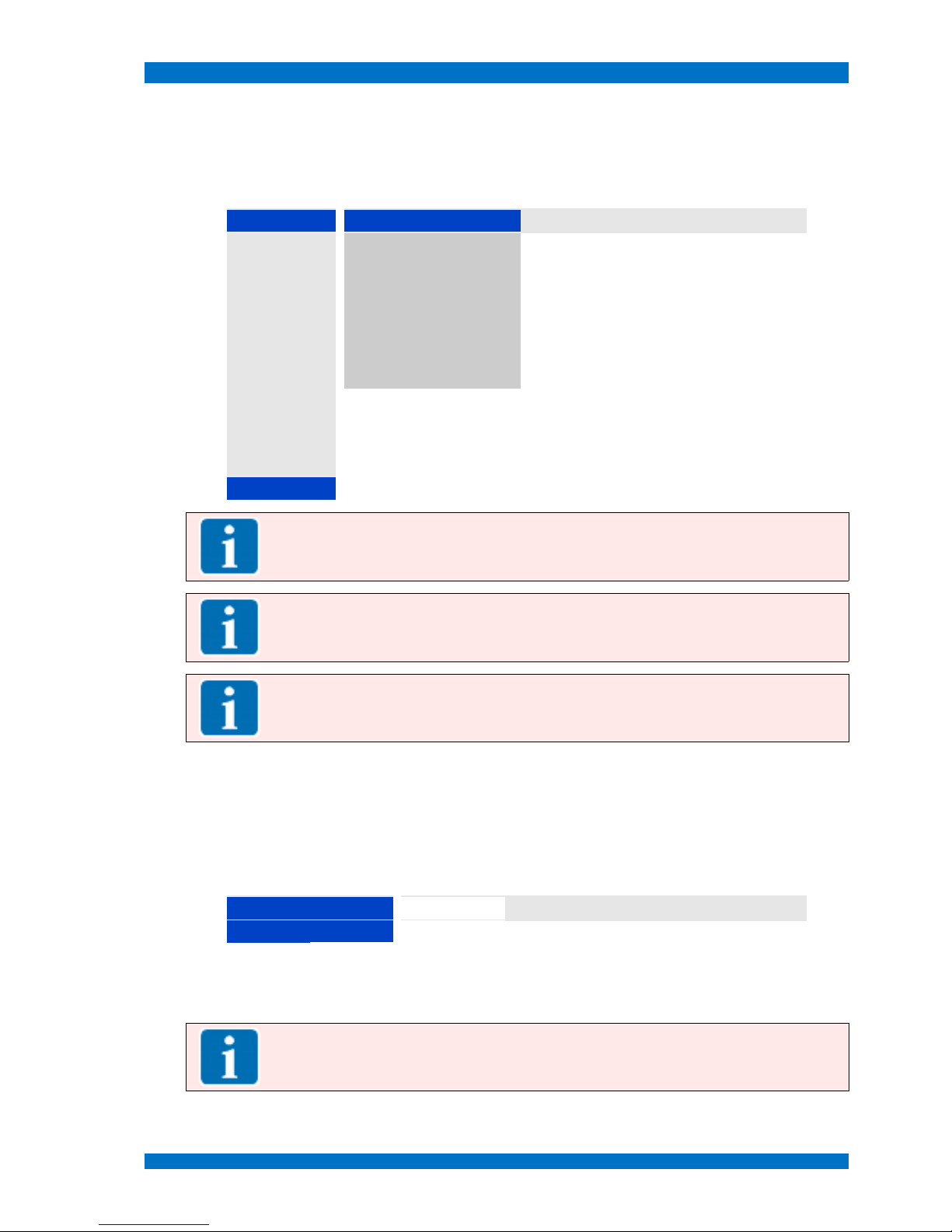
Main Menu SPARROWHAWK
Submenu Format for CCVS inputs
Select the FORMAT MENU from the INPUT MENU with the UP and DOWN keys and open the menu step
with the PLUS (V+) key.
The FORMAT MENU shows following operational steps when input CCVS 1 or CCVS 2 is selected:
INPUTS Format
Help
CCVS 1
AUTO
enables the auto-detection of the video standard
CCVS 2
NTSC
shows or enables the standard NTSC
Y/C
PAL
shows or enables the standard PAL
CAV
SECAM
shows or enables the standard SECAM
SDI 1
CAV Format: RGB
selects the RGB color space for the CAV input
SDI 2
CAV Format: YUV
selects the YUV color space for the CAV input
HD SDI 1
WSS
enables the WSS feature
HD SDI 2
VGA 1
VGA 2
DVI
Format
2
Note: Best format mode to operate the monitor is AUTO. When AUTO is enabled, the
incoming signal will be automatically recognized and the monitor automatically configured to
display the correct format.
Note: Component Analog Video (CAV) can be feed as RGB or YUV related color space. Select
the corresponding color space to display component video correctly.
Note: In some cases the video signal contains a WSS (wide screen signal) information within
his ancillary data and switches the monitor automatically to the correct aspect ratio. This
mode is available for SDI and CCVS signals only.
Close and save this menu step by pushing the MENU key once.
Submenu WSS
Select the WSS MENU from the INPUTS - FORMAT MENU when SDI or CCVS input is selected with the UP
and DOWN keys and open the menu step with the PLUS (V+) key.
The WSS MENU shows following operational steps:
Format
Help
WSS
WSS detects wide screen signals automatically from the
WSS data within the signal
Only when the displayed signal contains the wide screen signal pulse in his ancillary date and the
WSS feature is enabled the aspect ratio follows the signal.
Note: In some cases the video signal contains a WSS (wide screen signal) information within
his ancillary data and switches the monitor automatically to the correct aspect ratio. This
mode is available for SDI and CCVS signals only.
Close and save this menu step by pushing the MENU key once.
© 02.07 TAMUZ - LCD Video Monitors LSM Digital Broadcast Monitor Page - 46 -

Main Menu SPARROWHAWK
Submenu Format for VGA inputs
Select the FORMAT MENU from the INPUT MENU with the UP and DOWN keys and open the menu step
with the PLUS (V+) key.
The FORMAT MENU shows following operational steps when input VGA 1 or VGA 2 is selected:
INPUTS Format
Help
CCVS 1
Auto Sync Detect
enables the auto-detection of the video standard
CCVS 2
HV Sync
enables the mode separated H and V sync
Y/C
Composite Sync
enables the mode composite sync
CAV
Sync on Green
enables the mode sync on green
SDI 1
C-Sync Filter
Off
enables the composite sync filter
SDI 2
Edge
1st
selects the edge to trigger the sync
HD SDI 1
Coast lines
7
selects how many lines to detect for sync
HD SDI 2
SoG Level
-170 mV
selects the value of the sync on green level
VGA 1
H-Clamp
8
selects how many frames to detect a new sync
VGA 2
DVI
Format
2
Note: Best format mode to operate the monitor is AUTO. When AUTO is enabled, the
incoming signal will be automatically recognized and the monitor automatically configured to
display the correct format.
Note: In case of SoG signals the selections Edge, SoG Level and H-Clamp helps to adjust the
monitor to uncommon signals to display the graphic video correctly.
Close and save this menu step by pushing the MENU key once.
© 02.07 TAMUZ - LCD Video Monitors LSM Digital Broadcast Monitor Page - 47 -

Main Menu SPARROWHAWK
Scaling Menu
Select the INPUT MENU from the MAIN MENU with the UP and DOWN keys and open the menu step with
the PLUS (V+) key.
The INPUT MENU shows following operational steps:
TAMUZ LCD SCALING
Help
INPUTS
2
4 : 3
selects the aspect ratio 4:3
SCALING
2
16 : 9
selects the aspect ratio 16:9
IMAGE
2
14 : 9
selects the aspect ratio 14:9
KEYBOARD
2
1 : 1
selects the aspect ratio 1:1, no pixel interpolation
SYSTEM
2
2 : 1
selects the aspect ratio 2:1, doubles the pixel
Full Screen
selects the aspect ratio full screen
Scan Mode
2
opens the sub menu SCAN MODE
Mirror Off opens the sub menu MIRROR
Signal
2
opens the sub menu SIGNAL
Display
2
opens the sub menu DISPLAY
Zoom
2
opens the sub menu ZOOM
Reset
888
resets all custom settings back to default
Note: Some of the sub menus may be different regarding to the selected video input.
Close and save this menu step by pushing the MENU key once.
© 02.07 TAMUZ - LCD Video Monitors LSM Digital Broadcast Monitor Page - 48 -

Main Menu SPARROWHAWK
Submenu Scan Mode
Select the SCAN MODE MENU from the SCALING MENU with the UP and DOWN keys and open the menu
step with the PLUS (V+) key.
The SCAN MODE MENU shows following operational steps:
SCALING Scan Mode
Help
4 : 3
Underscan
selects the Underscan mode (shows all lines)
16 : 9
Normal
selects the Normal mode (active area)
14 : 9
Overscan
selects the Overscan mode (-10%)
1 : 1
Zoom
selects the Zoom mode (user definable)
2 : 1
Full Screen
Scan Mode
2
Mirror Off
Signal
2
Display
2
Zoom
2
Reset
8
Note: The NORMAL mode shows the active area of any kind of video signal on the screen. In
the UNDERSCAN mode all lines, even the sync area, of the signals becomes visible.
Close and save this menu step by pushing the MENU key once.
© 02.07 TAMUZ - LCD Video Monitors LSM Digital Broadcast Monitor Page - 49 -

Main Menu SPARROWHAWK
Submenu Mirror
Select the MIRROR MENU from the SCALING MENU with the UP and DOWN keys and open the menu step
with the PLUS (V+) key.
This feature may be helpful to turn the displayed image when the monitor is used in tele-prompter situation or head-over.
standard monitor in NORMAL color mode, 576i signal at input standard monitor in H mirror mode, 576i signal at input
standard monitor in V mirror mode, 576i signal at input standard monitor in H+V mirror mode, 576i signal at input
The MIRROR MENU shows following operational steps:
SCALING Mirror
Help
4 : 3
Off selects the Mirror mode OFF (no mirroring)
16 : 9
H selects the Mirror mode horizontally
14 : 9
V selects the Mirror mode vertically
1 : 1
H+V selects the Mirror mode horizontally and vertically
2 : 1
Full Screen
Scan Mode
2
Mirror Off
Signal
2
Display
2
Zoom
2
Reset
8
© 02.07 TAMUZ - LCD Video Monitors LSM Digital Broadcast Monitor Page - 50 -

Main Menu SPARROWHAWK
Note: The MIRROR mode depends to the capability of the specific LCD panel. With some
LCD panels not all functions may be available.
Close and save this menu step by pushing the MENU key once.
© 02.07 TAMUZ - LCD Video Monitors LSM Digital Broadcast Monitor Page - 51 -

Main Menu SPARROWHAWK
Submenu Signal for HDSDI inputs
Select the SIGNAL MENU from the SCALING MENU with the UP and DOWN keys and open the menu step
with the PLUS (V+) key.
The SIGNAL MENU shows following operational steps when HDSDI input is selected:
SCALING Signal
Help
4 : 3
x-Position 0 Adjust the horizontal image position on the screen.
Note: Selecting this menu step with the PLUS (V+) or
MINUS (V-) key for an individual setting. The value is limited
to the maximal TV line width.
16 : 9
y-Position -16 Adjust the vertical image position on the screen.
Note: Selecting this menu step with the PLUS (V+) or
MINUS (V-) key for an individual setting. The value is limited
to the maximal TV frame width.
14 : 9
Pixel 1920 Adjust how many pixels becomes sampled horizontally.
Note: Selecting this menu step with the PLUS (V+) or
MINUS (V-) key for an individual setting. The value is limited
to the maximal TV line width, regarding to the TV standard
(best for PAL is 940 samples).
1 : 1
Lines 1080i Adjust how many lines becomes sampled horizontally.
Note: Selecting this menu step with the PLUS (V+) or
MINUS (V-) key for an individual setting. The value is limited
to the maximal TV frame lines, regarding to the TV standard
(best for PAL is 576 lines).
2 : 1
P-I iFilm Selects the mode for interpolation of interlaced signals.
iSport = best for fast moving footage
iFilm = best for slow moving footage
p = for progressive footage only
sf = good for interlaced footage
Full Screen
Scan Mode
2
Mirror Off
Signal
2
Display
2
Zoom
2
Reset
8
Note: The processing mode effects the vertical resolution of interlaced footage. Select
carefully the best processing mode by toggling through the modes.
Note: The monitor stores and remembers the selected de-interlacer mode for the specific
signal and select this mode when the signal is detected next time.
Close and save this menu step by pushing the MENU key once.
Submenu P-I for interlaced HD-SDI Signals
Select the P-I MENU from the SIGNAL MENU with the UP and DOWN keys and enable the menu step
with the PLUS (V+) key.
Note: The iSport mode is the factory default setup for interlaced HD signals
© 02.07 TAMUZ - LCD Video Monitors LSM Digital Broadcast Monitor Page - 52 -

Main Menu SPARROWHAWK
T
he P-I MENU for interlaced HD-SDI signals shows following operational steps:
SIGNAL P-I
Help
x-Position 0 iSport fast de-interlacing, each field builds a frame
y-Position -16 iFilm high-end de-interlacing, 4 fields builds a frame
Pixel 1920 p progressive mode, odd and even builds a frame
Lines 1080i sF segmented frame, odd + even are melted to a frame
P-I iSport
Note: The P-I feature allows to find the best de-interlacing mode for different video formats
and sources. Please use the P mode for film related footage only.
Close and save this menu step by pushing the MENU key once.
This feature may be helpful to adjust the processing of de-interlacing regarding to the type of footage.
Still picture of an ODD field from a 1080i signal, shows 540 lines of
content only
De-interlacer in iSport mode. In each odd and even field all the lines are
doubled to build a frame. Fast processing with half vertical resolution in
each displayed frame. Good for fast moving images.
De-interlacer in iFilm mode. The odd and even field of a frame build a
frame, processed with adaptive de-interlacing filter, covering four fields.
Slower processing with full vertical resolution in each displayed frame.
De-interlacer in sF mode. A compromise mode, melting the odd and
even field to be a frame. Shows jaggies when parts of the image moves.
Medium processing with full vertical resolution in each displayed frame.
Note: Using the iSport mode, the displayed images may have flicker at horizontal edges,
cause the content is only in one of the two fields (odd or even) visible.
Note: Using the iFilm mode, the processing needs more time regarding the four field adaptive
de-interlacing. The displayed images may be later as in the other processing modes.
Note: Using the sF mode, the displayed images may have jaggies at vertical edges, cause
the content may be moved to a new geometrical position.
© 02.07 TAMUZ - LCD Video Monitors LSM Digital Broadcast Monitor Page - 53 -

Main Menu SPARROWHAWK
S
ubmenu P-I for progressive HD-SDI Signals
Select the P-I MENU from the SIGNAL MENU with the UP and DOWN keys and enable the menu step
with the PLUS (V+) key.
Note: The p mode is the factory default setup for progressive HD signals
The P-I MENU for progressive HD-SDI signals shows following operational steps:
SIGNAL P-I
Help
x-Position 0 p progressive mode, odd and even builds a frame
y-Position -16 iFilm high-end de-interlacing, 4 fields builds a frame
Pixel 1920
Lines 1080i
P-I iSport
Note: The P-I feature allows to find the best de-interlacing mode for different video formats
and sources. Please use the P mode for film related footage only.
Close and save this menu step by pushing the MENU key once.
This feature may be helpful to adjust the processing of de-interlacing regarding to the type of footage.
De-interlacer in p mode. Progressive signals will be not de-interlaced
and displayed in the original 1080 line resolution. Fast processing with
full vertical resolution in each displayed frame.
De-interlacer in iFilm mode. The odd and even field of a frame build a
frame, processed with adaptive de-interlacing filter, covering four fields.
Slower processing with full vertical resolution in each displayed frame.
Note: Using the p mode when feeding original P footage to the monitor. This will be selected
automatically when a P-signal is detected.
Note: Using the iFilm mode, the processing needs more time regarding the four field adaptive
de-interlacing. The displayed images may be later as in the other processing modes.
© 02.07 TAMUZ - LCD Video Monitors LSM Digital Broadcast Monitor Page - 54 -

Main Menu SPARROWHAWK
Submenu Signal for SDI inputs
Select the SIGNAL MENU from the SCALING MENU with the UP and DOWN keys and open the menu step
with the PLUS (V+) key.
The SIGNAL MENU shows following operational steps when SDI input is selected:
SCALING Signal
Help
4 : 3
x-Position 0 Adjust the horizontal image position on the screen.
Note: Selecting this menu step with the PLUS (V+) or
MINUS (V-) key for an individual setting. The value is limited
to the maximal TV line width.
16 : 9
y-Position -16 Adjust the vertical image position on the screen.
Note: Selecting this menu step with the PLUS (V+) or
MINUS (V-) key for an individual setting. The value is limited
to the maximal TV frame width.
14 : 9
Pixel 1920 Adjust how many pixels becomes sampled horizontally.
Note: Selecting this menu step with the PLUS (V+) or
MINUS (V-) key for an individual setting. The value is limited
to the maximal TV line width, regarding to the TV standard
(best for PAL is 940 samples).
1 : 1
Lines 1080i Adjust how many lines becomes sampled horizontally.
Note: Selecting this menu step with the PLUS (V+) or
MINUS (V-) key for an individual setting. The value is limited
to the maximal TV frame lines, regarding to the TV standard
(best for PAL is 576 lines).
2 : 1
P-I iFilm Selects the mode for interpolation of interlaced signals.
iSport = best for fast moving footage
iFilm = best for slow moving footage
p = for progressive footage only
sf = good for interlaced footage
Full Screen
Scan Mode
2
Mirror Off
Signal
2
Display
2
Zoom
2
Reset
8
Note: The processing mode effects the vertical resolution of interlaced footage. Select
carefully the best processing mode by toggling through the modes.
Note: The monitor stores and remembers the selected de-interlacer mode for the specific
signal and select this mode when the signal is detected next time.
Close and save this menu step by pushing the MENU key once.
Submenu P-I interlaced for SD-SDI Signals
Select the P-I MENU from the SIGNAL MENU with the UP and DOWN keys and enable the menu step
with the PLUS (V+) key.
Note: The iFilm mode is the factory default setup for interlaced SD signals
© 02.07 TAMUZ - LCD Video Monitors LSM Digital Broadcast Monitor Page - 55 -

Main Menu SPARROWHAWK
T
he P-I MENU for interlaced SD-SDI signals shows following operational steps:
SIGNAL P-I
Help
x-Position 0 iSport fast de-interlacing, each field builds a frame
y-Position -16 iFilm high-end de-interlacing, 4 fields builds a frame
Pixel 720 p progressive mode, odd and even builds a frame
Lines 576i sF segmented frame, odd + even are melted to a frame
P-I iSport
Note: The P-I feature allows to find the best de-interlacing mode for different video formats
and sources. Please use the P mode for film related footage only.
Close and save this menu step by pushing the MENU key once.
This feature may be helpful to adjust the processing of de-interlacing regarding to the type of footage.
Still picture of an ODD field from a 576i / 480i signal, shows 283 / 240
lines of content only
De-interlacer in iSport mode. In each odd and even field all the lines are
doubled to build a frame. Fast processing with half vertical resolution in
each displayed frame. Good for fast moving images.
De-interlacer in iFilm mode. The odd and even field of a frame build a
frame, processed with adaptive de-interlacing filter, covering four fields.
Slower processing with full vertical resolution in each displayed frame.
De-interlacer in sF mode. A compromise mode, melting the odd and
even field to be a frame. Shows jaggies when parts of the image moves.
Medium processing with full vertical resolution in each displayed frame.
Note: Using the iSport mode, the displayed images may have flicker at horizontal edges,
cause the content is only in one of the two fields (odd or even) visible.
Note: Using the iFilm mode, the processing needs more time regarding the four field adaptive
de-interlacing. The displayed images may be later as in the other processing modes.
Note: Using the sF mode, the displayed images may have jaggies at vertical edges, cause
the content may be moved to a new geometrical position.
© 02.07 TAMUZ - LCD Video Monitors LSM Digital Broadcast Monitor Page - 56 -

Main Menu SPARROWHAWK
Note: Using the p mode for interlaced signals is not the best idea. The de-interlacing is
disabled and the displayed images shows movement artefacts.
© 02.07 TAMUZ - LCD Video Monitors LSM Digital Broadcast Monitor Page - 57 -

Main Menu SPARROWHAWK
Submenu Display
Select the DISPLAY MENU from the SCALING MENU with the UP and DOWN keys and open the menu step
with the PLUS (V+) key.
The DISPLAY MENU shows following operational steps:
SCALING Display
Help
4 : 3
x-Position 0 Adjust the horizontal position on the screen.
Note: Selecting this menu step with the PLUS (V+) or
MINUS (V-) key for an individual setting. The value is limited
to the native panel resolution.
16 : 9
y-Position 0 Adjust the vertical position on the screen.
Note: Selecting this menu step with the PLUS (V+) or
MINUS (V-) key for an individual setting. The value is limited
to the native panel resolution.
14 : 9
Pixel 1280 Adjust the horizontal size for the active area of the LCD panel.
Note: Selecting this menu step with the PLUS (V+) or
MINUS (V-) key for an individual setting. The value is limited
to the native panel resolution.
1 : 1
Lines 768 Adjust the vertical size for the active area of the LCD panel.
Note: Selecting this menu step with the PLUS (V+) or
MINUS (V-) key for an individual setting. The value is limited
to the native panel resolution.
2 : 1
Full Screen
Scan Mode
2
Mirror Off
Signal
2
Display
2
Zoom
2
Reset
8
Note: Modifying the pixel and lines of the display may effect the used area of the display.
Close and save this menu step by pushing the MENU key once.
© 02.07 TAMUZ - LCD Video Monitors LSM Digital Broadcast Monitor Page - 58 -

Main Menu SPARROWHAWK
Submenu Zoom
Select the ZOOM MENU from the SCALING MENU with the UP and DOWN keys and open the menu step
with the PLUS (V+) key.
The ZOOM MENU shows following operational steps:
SCALING Zoom Setup
Help
4 : 3
x-Factor 2.00 Adjust the horizontal ZOOM factor to magnify the image on
screen.
Note: Selecting this menu step with the PLUS (V+) or
MINUS (V-) key for an individual setting. Values between 0 to
100 are possible.
16 : 9
y-Factor 2.00 Adjust the vertical ZOOM factor to magnify the image on
screen.
Note: Selecting this menu step with the PLUS (V+) or
MINUS (V-) key for an individual setting. Values between 0 to
100 are possible.
14 : 9
x-Position 0 Adjust the horizontal position on the screen.
Note: Selecting this menu step with the PLUS (V+) or
MINUS (V-) key for an individual setting. The value is limited
to the native panel resolution.
1 : 1
y-Position 0 Adjust the vertical position on the screen.
Note: Selecting this menu step with the PLUS (V+) or
MINUS (V-) key for an individual setting. The value is limited
to the native panel resolution.
2 : 1
Full Screen
Scan Mode
2
Mirror Off
Signal
2
Display
2
Zoom
2
Reset
8
Note: To enable the Zoom, use the menu SCAN MODE and enable this feature there.
Close and save this menu step by pushing the MENU key once.
© 02.07 TAMUZ - LCD Video Monitors LSM Digital Broadcast Monitor Page - 59 -

Main Menu SPARROWHAWK
Submenu Reset
Select the RESET MENU from the SCALING MENU with the UP and DOWN keys and open the menu step
with the PLUS (V+) key.
The RESET MENU shows following operational steps:
SCALING
Help
4 : 3
16 : 9
14 : 9
1 : 1
2 : 1
Full Screen
Scan Mode
2
Mirror Off
Signal
2
Display
2
Zoom
2
Reset
8
resets all scaling functions back to default, activate with PLUS
Note: RESET sets all setups from the SCALING menu back to the default values.
Close and save this menu step by pushing the MENU key once.
© 02.07 TAMUZ - LCD Video Monitors LSM Digital Broadcast Monitor Page - 60 -

Main Menu SPARROWHAWK
Image Menu
Select the IMAGE MENU from the MAIN MENU with the UP and DOWN keys and open the menu step with
the PLUS (V+) key.
T
he IMAGE MENU shows following operational steps:
TAMUZ LCD IMAGE
Help
INPUTS
2
Brightness 0 Adjust the BRIGHTNESS value of the screen.
Note: Selecting this menu step with the PLUS (V+)
or MINUS (V-) key for an individual setting. Values
between -128 to +128 are possible.
SCALING
2
Contrast 0 Adjust the CONTRAST value of the screen.
Note: Selecting this menu step with the PLUS (V+)
or MINUS (V-) key for an individual setting. Values
between -128 to +128 are possible.
IMAGE
2
Saturation 0 Adjust the SATURATION value of the screen.
Note: Selecting this menu step with the PLUS (V+)
or MINUS (V-) key for an individual setting. Values
between -128 to +128 are possible.
KEYBOARD
2
Backlight 15 Shows the BACKLIGHT value of the screen.
Note: The setup must be done in the color
adjustment menu.
SYSTEM
2
Gamma
2
opens the GAMMA setup menu
Color Temp. 6504 toggle for the right COLOR TEMPERATURE
Color adjust
2
opens the COLOR ADJUST setup menu
B/W
selects the B/W feature
Negative
selects the NEGATIVE feature
R/G/B
2
opens the R/G/B setup menu
Freeze
selects the FREEZE feature
Aperture
2
opens the APERTURE setup menu
Note: Some of the sub menus may be different from the selected video input.
Close and save this menu step by pushing the MENU key once.
© 02.07 TAMUZ - LCD Video Monitors LSM Digital Broadcast Monitor Page - 61 -

Main Menu SPARROWHAWK
Submenu Gamma
Select the GAMMA MENU from the IMAGE MENU with the UP and DOWN keys and open the menu step
with the PLUS (V+) key.
The SCAN GAMMA MENU shows following operational steps:
IMAGE Gamma
Help
Brightness 0 Off
disables the GAMMA correction
Contrast 0 1.8
selects the 1.8 gamma correction factor
Saturation 0 2.2
selects the 2.2 gamma correction factor
Backlight 15
Gamma
2
Color Temp. 6504
Color adjust
2
B/W
Negative
R/G/B
2
Freeze
Aperture
2
Note: When GAMMA is set to OFF mode, the display uses the no gamma correction factor to
adjust the displayed image. The monitor uses the default correction of the specific LCD panel.
Close and save this menu step by pushing the MENU key once.
© 02.07 TAMUZ - LCD Video Monitors LSM Digital Broadcast Monitor Page - 62 -

Main Menu SPARROWHAWK
Submenu Color Temperature
Select the COLOR TEMPERATURE MENU from the IMAGE MENU with the UP and DOWN keys and open the
menu step with the PLUS (V+) key.
The COLOR TEMPERATURE MENU shows following operational steps:
IMAGE Color Temperature
Help
Brightness 0 user selects the user setup (opens the color adjust menu)
Contrast 0 3200 selects the color temperature 3200 K
Saturation 0 3300 selects the color temperature 3200 K
Backlight 15 3400 selects the color temperature 3400 K
Gamma
2
3500 selects the color temperature 3500 K
Color Temp. 6504 3600 selects the color temperature 3600 K
Color adjust
2
3700 selects the color temperature 3700 K
B/W
3800 selects the color temperature 3800 K
Negative
3900 selects the color temperature 3900 K
R/G/B
2
4000 selects the color temperature 4000 K
Freeze
4100 selects the color temperature 4100 K
Aperture
2
4200 selects the color temperature 4200 K
4300 selects the color temperature 4300 K
4400 selects the color temperature 4400 K
4500 selects the color temperature 4500 K
4600 selects the color temperature 4600 K
4700 selects the color temperature 4700 K
4800 selects the color temperature 4800 K
4900 selects the color temperature 4900 K
5000 selects the color temperature 5000 K
5100 selects the color temperature 5100 K
5200 selects the color temperature 5200 K
5300 selects the color temperature 5300 K
5400 selects the color temperature 5400 K
5500 selects the color temperature 5500 K
5600 selects the color temperature 5600 K
5700 selects the color temperature 5700 K
5800 selects the color temperature 5800 K
5900 selects the color temperature 5900 K
6000 selects the color temperature 6000 K
6100 selects the color temperature 6100 K
6200 selects the color temperature 6200 K
6300 selects the color temperature 6300 K
6400 selects the color temperature 6400 K
6500 selects the color temperature 6500 K
6504 selects the color temperature 6504 K (D65)
6600 selects the color temperature 6600 K
6700 selects the color temperature 6700 K
6800 selects the color temperature 6800 K
6900 selects the color temperature 6900 K
© 02.07 TAMUZ - LCD Video Monitors LSM Digital Broadcast Monitor Page - 63 -

Main Menu SPARROWHAWK
7000 selects the color temperature 7000 K
7100 selects the color temperature 7100 K
7200 selects the color temperature 7200 K
7300 selects the color temperature 7300 K
7400 selects the color temperature 7400 K
7500 selects the color temperature 7500 K
7600 selects the color temperature 7600 K
7700 selects the color temperature 7700 K
7800 selects the color temperature 7800 K
7900 selects the color temperature 7900 K
8000 selects the color temperature 8000 K
8100 selects the color temperature 8100 K
8200 selects the color temperature 8200 K
8300 selects the color temperature 8300 K
8400 selects the color temperature 8400 K
8500 selects the color temperature 8500 K
8600 selects the color temperature 8600 K
8700 selects the color temperature 8700 K
8800 selects the color temperature 8800 K
8900 selects the color temperature 8900 K
9000 selects the color temperature 9000 K
9100 selects the color temperature 9100 K
9200 selects the color temperature 9200 K
9300 selects the color temperature 9300 K
9400 selects the color temperature 9400 K
9500 selects the color temperature 9500 K
standard monitor in NORMAL D65 color mode, 576i signal at input standard monitor in 3200 K color mode, 576i signal at input
In COLOR TEMPERATUR 3200 K mode the image will be displayed in individual aligned color temperature.
Note: Only when COLOR TEMPERATURE is set to USER mode, the menu for manual
adjustments is enabled. Default color temperature is D65.
Close and save this menu step by pushing the MENU key once.
© 02.07 TAMUZ - LCD Video Monitors LSM Digital Broadcast Monitor Page - 64 -

Main Menu SPARROWHAWK
Submenu Color Adjustments
Select the COLOR ADJUSTMENTS MENU from the IMAGE MENU with the UP and DOWN keys and open the
menu step with the PLUS (V+) key.
The COLOR ADJUSTMENTS MENU shows following operational steps:
IMAGE Color Adjust
Help
Brightness 0 White R 0 adjust the white color value within the R channel
Contrast 0 White G 0 adjust the white color value within the G channel
Saturation 0 White B 0 adjust the white color value within the B channel
Backlight 15 Grey R 0 adjust the grey color value within the R channel
Gamma
2
Grey G 0 adjust the grey color value within the G channel
Color Temp. 6504 Grey B 0 adjust the grey color value within the B channel
Color adjust
2
Black R 0 adjust the black color value within the R channel
B/W
Black G 0 adjust the black color value within the G channel
Negative
Black B 0 adjust the black color value within the B channel
R/G/B
2
Freeze
Aperture
2
Only when COLOR is disabled the image will be displayed in full color.
standard monitor in NORMAL color mode, 576i signal at input standard monitor in COLOR color mode, 576i signal at input
In NORMAL mode the image will be displayed in full color.
In COLOR mode the image will be displayed in individual aligned colors.
Note: Selecting this menu step with the PLUS (V+)orMINUS (V-) key for an individual
setting. Values between -128 to +128 are possible.
Close and save this menu step by pushing the MENU key once.
© 02.07 TAMUZ - LCD Video Monitors LSM Digital Broadcast Monitor Page - 65 -

Main Menu SPARROWHAWK
Submenu B/W
Select the B/W MENU from the IMAGE MENU with the UP and DOWN keys and enable the menu step
with the PLUS (V+) key.
The B/W MENU shows following operational steps:
IMAGE B / W
Help
Brightness 0 B/W
enables the B/W function
Contrast 0
Saturation 0
Backlight 15
Gamma
2
Color Temp. 6504
Color adjust
2
B/W
Negative
R/G/B
2
Freeze
Aperture
2
Only when B/W is disabled the image will be displayed in full color.
standard monitor in NORMAL color mode, 576i signal at input standard monitor in B/W color mode, 576i signal at input
In NORMAL mode the image will be displayed in full color.
In B/W mode the image will be displayed in black/white colors.
Note: The B/W feature is not available for SDI inputs, It disables the color and displays a
monochrome image only.
Close and save this menu step by pushing the MENU key once.
© 02.07 TAMUZ - LCD Video Monitors LSM Digital Broadcast Monitor Page - 66 -

Main Menu SPARROWHAWK
Submenu Negative
Select the NEGATIVE MENU from the IMAGE MENU with the UP and DOWN keys and open the menu
step with the PLUS (V+) key.
The NEGATIVE MENU shows following operational steps:
IMAGE NEGATIVE
Help
Brightness 0 Negative
enables the negative function
Contrast 0
Saturation 0
Backlight 15
Gamma
2
Color Temp. 6504
Color adjust
2
B/W
Negative
R/G/B
2
Freeze
Aperture
2
Only when NEGATIVE is disabled the image will be displayed in full color.
standard monitor in NORMAL color mode, 576i signal at input standard monitor in NEGATIVE color mode, 576i signal at input
In NORMAL mode the image will be displayed in full color.
In NEGATIVE mode the image will be displayed in inverses colors.
Note: The NEGATIVE feature inverts the color and displays a negative image only.
Close and save this menu step by pushing the MENU key once.
© 02.07 TAMUZ - LCD Video Monitors LSM Digital Broadcast Monitor Page - 67 -

Main Menu SPARROWHAWK
Submenu R/G/B
Select the R/G/B MENU from the IMAGE MENU with the UP and DOWN keys and open the menu step with
the PLUS (V+) key.
The R/G/B MENU shows following operational steps:
IMAGE R / G / B
Help
Brightness 0 R
enables the R channel
Contrast 0 G
enables the G channel
Saturation 0 B
enables the B channel
Backlight 15
Gamma
2
Color Temp. 6504
Color adjust
2
B/W
Negative
R/G/B
2
Freeze
Aperture
2
Only when all three channels are enabled the image will be displayed in full color.
standard monitor in NORMAL color mode, 576i signal at input standard monitor in RED color mode, 576i signal at input
standard monitor in GREEN color mode, 576i signal at input standard monitor in BLUE color mode, 576i signal at input
In NORMAL mode the image will be displayed in full color.
In RED mode the image will be displayed in red color only.
In GREEN mode the image will be displayed in green color only.
© 02.07 TAMUZ - LCD Video Monitors LSM Digital Broadcast Monitor Page - 68 -

Main Menu SPARROWHAWK
I
n BLUE mode the image will be displayed in blue color only.
Note: When all three channels R / G / B are disabled, the screen will show black image.
Note: If the monitor is always dark; the R / G / B function may be activated in all three
channels. To switch back you need to connect a PC and use the MRC program to reset for a
visible image.
C
lose and save this menu step by pushing the MENU key once.
© 02.07 TAMUZ - LCD Video Monitors LSM Digital Broadcast Monitor Page - 69 -

Main Menu SPARROWHAWK
Submenu Aperture
Select the APERTURE MENU from the IMAGE MENU with the UP and DOWN keys and open the menu step
with the PLUS (V+) key.
The APERTURE MENU shows following operational steps:
IMAGE Aperture
Help
Brightness 0 Enhancement 0 enables the enhancement for high frequencies
Contrast 0 Detail min.
selects detail edge detection to minimum
Saturation 0 Detail medium
selects detail edge detection to medium
Backlight 15 Detail max.
selects detail edge detection to maximum
Gamma
2
Color Temp. 6504
Color adjust
2
B/W
Negative
R/G/B
2
Freeze
Aperture
2
Note: Using aperture features the edges within displayed images can be sharpen. Use this
item carefully, otherwise the monitored images looks artificial.
Close and save this menu step by pushing the MENU key once.
© 02.07 TAMUZ - LCD Video Monitors LSM Digital Broadcast Monitor Page - 70 -

Main Menu SPARROWHAWK
Keyboard Menu
Select the KEYBORD MENU from the MAIN MENU with the UP and DOWN keys and open the menu step
with the PLUS (V+) key.
T
he KEYBOARD MENU shows following operational steps:
TAMUZ LCD KEYBOARD
Help
INPUTS
2
Down Default enables and select the function of the button DOWN
SCALING
2
Up Default enables and select the function of the button UP
IMAGE
2
Plus Default enables and select the function of the button PLUS
KEYBOARD
2
Minus Default enables and select the function of the button MINUS
SYSTEM
2
The list for available items within the KEYBOARD MENU see below.
Note: Only when set to DEFAULT, the function named on the front of the SPARROWHAWK
series monitor are active, otherwise your individual programmed functions may occurs.
Close and save this menu step by pushing the MENU key once.
© 02.07 TAMUZ - LCD Video Monitors LSM Digital Broadcast Monitor Page - 71 -

Main Menu SPARROWHAWK
Submenu Keyboard
Select the KEYBOARD FUNCTIONS MENU from the KEYBOARD MENU with the UP and DOWN keys and open
the menu step with the PLUS (V+) key.
The KEYBOARD FUNCTIONS for all four menu keys DOWN – UP – PLUS – MINUS:
KEYBOARD Keyboard
Function
Help
Down Default Default enables the default direct access function for this key
Up Default VGA 1 selects the VGA 1 input as direct access function for this key
Plus Default VGA 2 selects the VGA 2 input as direct access function for this key
Minus Default DVI selects the DVI input as direct access function for this key
CCVS 1 selects the CCVS 1 input as direct access function for this key
CCVS 2 selects the CCVS 2 input as direct access function for this key
Y/C selects the Y/C input as direct access function for this key
RGB / YUV selects the RGB/YUV input as direct access function for this key
SDI 1 selects the SDI 1 input as direct access function for this key
SDI 2 selects the SDI 1 input as direct access function for this key
HDSDI 1 selects the HDSDI 1 input as direct access function for this key
HDSDI 2 selects the HDSDI 1 input as direct access function for this key
Brightness - selects decreasing brightness as direct access function for this key
Brightness + selects increasing brightness as direct access function for this key
Contrast - selects decreasing contrast as direct access function for this key
Contrast + selects increasing contrast as direct access function for this key
Saturation - selects decreasing saturation as direct access function for this key
Saturation + selects increasing saturation as direct access function for this key
4:3 selects the 4:3 aspect ratio as direct access function for this key
16:9 selects the 16:9 aspect ratio as direct access function for this key
Underscan selects the underscan mode as direct access function for this key
Overscan selects the overscan mode as direct access function for this key
B/W selects the black/white mode as direct access function for this key
Freeze selects the freeze mode as direct access function for this key
Note: Only when set to DEFAULT, the function named on the front of the SPARROWHAWK
series monitor are active, otherwise your individual programmed function occurs.
Close and save this menu step by pushing the MENU key once.
© 02.07 TAMUZ - LCD Video Monitors LSM Digital Broadcast Monitor Page - 72 -

Main Menu SPARROWHAWK
System Menu
Select the SYSTEM MENU from the MAIN MENU with the UP and DOWN keys and open the menu step
with the PLUS (V+) key.
T
he SYSTEM MENU shows following operational steps:
TAMUZ LCD SYSTEM
Help
INPUTS
2
Power On
2
selects the input the monitor starts with at power on
SCALING
2
Search
2
selects the inputs the monitor will search for
IMAGE
2
Processing
2
selects which type of processing will be used
KEYBOARD
2
Language
2
selects the language for the OSD menu
SYSTEM
2
OSD
2
opens the OSD setup menu
Wall
2
opens the WALL setup menu
RGB Adjust
2
opens the RGB ADJUSTMENTS setup menu
Auto Color
2
opens the RGB ADJUSTMENTS setup menu
Backlight
2
opens the AUTO COLOR setup menu
Anti Sticking
2
opens the ANTI STICKING setup menu
The list for available items within the KEYBOARD MENU see below.
Note: Some of the sub menus may be hidden for normal operation users. Please ask your
administrator to open the hidden menu section with the correct password.
Close and save this menu step by pushing the MENU key once.
© 02.07 TAMUZ - LCD Video Monitors LSM Digital Broadcast Monitor Page - 73 -

Main Menu SPARROWHAWK
Submenu Power On
Select the POWER ON MENU from the SYSTEMS MENU with the UP and DOWN keys and open the menu
step with the PLUS (V+) key.
The POWER ON MENU shows following operational steps:
SYSTEM Power On
Help
Power On
2
Last
monitor powers up with the last selected input
Search
2
CCVS 1
monitor always powers up with the CCVS 1 input
Processing
2
CCVS 2
monitor always powers up with the CCVS 2 input
Language
2
Y/C
monitor always powers up with the Y/C input
OSD
2
CAV
monitor always powers up with the CAV input
Wall
2
SDI 1
monitor always powers up with the SDI 1 input
RGB Adjust
2
SDI 2
monitor always powers up with the SDI 2 input
Auto Color
2
VGA 1
monitor always powers up with the VGA 1 input
Backlight
2
VGA 2
monitor always powers up with the VGA 2 input
Anti Sticking
2
DVI
monitor always powers up with the DVI input
HDSDI 1
monitor always powers up with the HDSDI input
HDSDI 2
monitor always powers up with the HDSDI input
Note: The SPARROWHAWK series monitors always powers up with the last selected input
source.
Close and save this menu step by pushing the MENU key once.
© 02.07 TAMUZ - LCD Video Monitors LSM Digital Broadcast Monitor Page - 74 -

Main Menu SPARROWHAWK
Submenu Search
Select the SEARCH MENU from the SYSTEMS MENU with the UP and DOWN keys and open the menu
step with the PLUS (V+) key.
The SEARCH MENU shows following operational steps:
SYSTEM Search
Help
Power On
2
CCVS 1
monitor searches for the CCVS 1 input, when valid
Search
2
CCVS 2
monitor searches for the CCVS 2 input, when valid
Processing
2
Y/C
monitor searches for the Y/C input, when valid
Language
2
CAV
monitor searches for the CAV input, when valid
OSD
2
SDI 1
monitor searches for the SDI 1 input, when valid
Wall
2
SDI 2
monitor searches for the SDI 1 input, when valid
RGB Adjust
2
VGA 1
monitor searches for the VGA 1 input, when valid
Auto Color
2
VGA 2
monitor searches for the VGA 1 input, when valid
Backlight
2
DVI
monitor searches for the DVI input, when valid
Anti Sticking
2
HDSDI
monitor searches for the HDSDI input, when valid
Note: The search mode takes place, when the standard input signal is not valid. So the
monitor will search for the next valid input.
Close and save this menu step by pushing the MENU key once.
© 02.07 TAMUZ - LCD Video Monitors LSM Digital Broadcast Monitor Page - 75 -

Main Menu SPARROWHAWK
Submenu Processing
Select the PROCESSING MENU from the SYSTEMS MENU with the UP and DOWN keys and open the menu
step with the PLUS (V+) key.
The PROCESSING MENU shows following operational steps:
SYSTEM Processing
Help
Power On
2
Interlace
The monitor interface operates in the interlace mode.
Here every field, odd and even, will be interpolated
into a single progressive frame separately using a
adaptive comb filter technology.
Search
2
Progressive
The monitor interface operates in the progressive
mode. Here every frame will be processed as a
progressive frame using a adaptive comb filter
technology. This mode allows full vertical resolution.
Processing
2
Asynchron
Enables the asynchronous mode.
When active, the monitor interface operates in
asynchronous mode. The image will be displayed
with the default TFT panel refresh rate and is not
synchronized to the incoming video.
Language
2
Full Colors
Sets the monitor to full color mode operation. All 16
million colors will be visible.
OSD
2
64 Colors
Sets the monitor to 64 color mode operation. The
visible colors are limited to 64 value's.
Wall
2
8 Colors
Sets the monitor to 8 color mode operation. The
visible colors are limited to 8 value's.
RGB Adjust
2
Auto Color
2
Backlight
2
Anti Sticking
2
Note: The progressive mode is best for slow moving footage or film based footage. It allows
full vertical resolution for interlaced formats.
Note: In some applications it may be the best to select the Asynchron mode. This helps to
provide image sticking effects during long time presentation of pattern images, f.e. in a control
room where transmission lines will be supervised.
Close and save this menu step by pushing the MENU key once.
© 02.07 TAMUZ - LCD Video Monitors LSM Digital Broadcast Monitor Page - 76 -

Main Menu SPARROWHAWK
Submenu Language
Select the LANGUAGE MENU from the SYSTEMS MENU with the UP and DOWN keys and open the menu
step with the PLUS (V+) key.
The LANGUAGE MENU shows following operational steps:
SYSTEM Language
Help
Power On
2
Deutsch
sets the monitor OSD to German language
Search
2
English
sets the monitor OSD to English language
Processing
2
French
sets the monitor OSD to French language
Language
2
Spanish
sets the monitor OSD to Spanish language
OSD
2
Italian
sets the monitor OSD to Italian language
Wall
2
RGB Adjust
2
Auto Color
2
Backlight
2
Anti Sticking
2
Note: The language menu selects the OSD language itself, and other value formats as well.
Close and save this menu step by pushing the MENU key once.
© 02.07 TAMUZ - LCD Video Monitors LSM Digital Broadcast Monitor Page - 77 -

Main Menu SPARROWHAWK
Submenu OSD
Select the OSD MENU from the SYSTEMS MENU with the UP and DOWN keys and open the menu step
with the PLUS (V+) key.
The OSD MENU shows following operational steps:
SYSTEM OSD
Help
Power On
2
Cascade
enables the cascade mode for the OSD menu
Search
2
Transparency 20 Adjust the TRANSPARENCY value of the OSD.
Note: Selecting this menu step with the PLUS (V+)
or MINUS (V-) key for an individual setting. Values
between 0 to 80 are possible.
Processing
2
Help
enables the help mode for the OSD menu
Language
2
OSD Time Never sets the OSD time out to your individual value
OSD
2
x-Position -200 Adjust the OSD menu x-position on the screen.
Wall
2
y-Position 20 Adjust the OSD menu y-position on the screen.
RGB Adjust
2
Auto Color
2
Backlight
2
Anti Sticking
2
Note: Within the OSD menu not every item displays a help text to describes that selected
item.
Close and save this menu step by pushing the MENU key once.
© 02.07 TAMUZ - LCD Video Monitors LSM Digital Broadcast Monitor Page - 78 -

Main Menu SPARROWHAWK
Submenu Wall
Select the WALL MENU from the SYSTEMS MENU with the UP and DOWN keys and open the menu step
with the PLUS (V+) key.
Using this feature, big monitor wall is possible to built without using an external image-split processor.
The interface of the SPARROWHAWK series monitors splits and position the inputs signal itself.
The WALL MENU shows following operational steps:
SYSTEM Display Wall
Help
Power On
2
Display Wall
enables the wall mode for this monitor
Search
2
Display No. 1 Sets the position for this monitor within the wall
configuration. Start counting in the upper left.
Processing
2
Displays hor. 2 Sets the number of monitors within horizontal
direction in this wall configuration.
Language
2
Displays vert. 2 Sets the number of monitors within vertical direction
in this wall configuration.
OSD
2
Border hor. 0 Adjusts the overlapping horizontal border area
between the monitors.
Wall
2
Border vert. 0 Adjusts the overlapping vertical border area between
the monitors.
RGB Adjust
2
Auto Color
2
Backlight
2
Anti Sticking
2
Note: When the wall feature is active, the displayed image is only a portion of the input signal.
Close and save this menu step by pushing the MENU key once.
© 02.07 TAMUZ - LCD Video Monitors LSM Digital Broadcast Monitor Page - 79 -

Main Menu SPARROWHAWK
Submenu RGB Adjust
Select the RGB ADJUST MENU from the SYSTEMS MENU with the UP and DOWN keys and open the menu
step with the PLUS (V+) key.
The RGB Adjust MENU shows following operational steps:
SYSTEM RGB Adjust
Help
Power On
2
VGA 1
Selects VGA 1 to be the source input to adjust the
A/D converter for the VGA signal path.
Search
2
VGA 2
Selects VGA 2 to be the source input to adjust the
A/D converter for the VGA signal path.
Processing
2
B/W
enables black and white mode
Language
2
Offset
2
opens the Offset menu (for service purpose only)
OSD
2
Gain
2
opens the Gain menu (for service purpose only)
Wall
2
RGB Adjust
2
Auto Color
2
Backlight
2
Anti Sticking
2
Note: This menu is normally hidden and for service purposes only. Do not use to modify for
your individual use.
Close and save this menu step by pushing the MENU key once.
© 02.07 TAMUZ - LCD Video Monitors LSM Digital Broadcast Monitor Page - 80 -

Main Menu SPARROWHAWK
Submenu Auto Color
Select the AUTO COLOR MENU from the SYSTEMS MENU with the UP and DOWN keys and open the menu
step with the PLUS (V+) key.
The AUTO COLOR MENU shows following operational steps:
SYSTEM Auto Color
Help
Power On
2
Probe Setup
2
opens the menu to select the type of the probe
Search
2
Calibrate
starts the automatically calibration for color
Processing
2
Brightness
starts the automatic calibration for brightness
Language
2
Measure
starts the manual measure mode
OSD
2
Status Idle shows the data activity at the probe port
Wall
2
x0shows the current x-value of the measured light
RGB Adjust
2
y0shows the current y-value of the measured light
Auto Color
2
Y cd/m
2
0 shows the current luma value of the measured light
Backlight
2
Whitepoint x 307 allows the individual setup for the x white point
Anti Sticking
2
Whitepoint y 321 allows the individual setup for the y white point
User Gamma
enables the measured user gamma
Note: This menu is normally hidden and for service purposes only. Do not use to modify for
your individual use. For more details see the service section of this manual.
Note: Only when User Gamma is enabled the measured LUT (look-up-table) effects the
displayed image. If not, the standard default LUT's will be used.
Close and save this menu step by pushing the MENU key once.
© 02.07 TAMUZ - LCD Video Monitors LSM Digital Broadcast Monitor Page - 81 -

Main Menu SPARROWHAWK
S
ubmenu Probe Setup
Select the PROBE SETUP MENU from the AUTO COLOR MENU with the UP and DOWN keys and open the
menu step with the PLUS (V+) key.
The PROBE SETUP MENU shows following operational steps:
Auto Color Probe Setup
Help
Probe Setup
2
TFM6
selects probe type TFM6 (THOMA)
Calibrate
PM5639
selects probe type PM5664 (DK-PTV)
Brightness
Pluto
selects probe type Pluto
Measure
Mode Fine toggles between FINE and COARSE mode
Status Idle Color K 6504 selects the reference color temperature
x 0 Gamma 2.2
enables the recommended TV gamma function
y0Dicom
enables the medical gamma function
Y cd/m
2
0Max Y 80 set the luminance value for the alignment
Whitepoint x 307 Default
8
reset to default setup
Whitepoint y 321
User Gamma
Note: To prepare any alignment use the Probe Setup menu, Select the correct type of probe,
the style of measuring and the values for color temperature, gamma and luminance!
Note: The alignment mode FINE is more precise and needs much more time to measure then
the mode COARSE.
Close and save this menu step by pushing the MENU key once.
© 02.07 TAMUZ - LCD Video Monitors LSM Digital Broadcast Monitor Page - 82 -

Main Menu SPARROWHAWK
S
ubmenu Calibrate
Select the CALIBRATE MENU from the AUTO COLOR MENU with the UP and DOWN keys and open the me-
nu step with the PLUS (V+) key.
The CALIBRATE MENU shows following operational steps:
Auto Color
Help
Probe Setup
2
Calibrate
The color calibration is an automatically process and
starts with some full color patterns to measure the
color space of the specific monitor TFT Panel.
Thereafter a ramp black-to-white will be measured to
write the individual LUT. The whole calibration take
about 4 to 10 minutes.
Brightness
Measure
Status Idle Indicates the measurement activity!
Only when „READY“ is shown, the measurement is
finished and set.
x0
y0
Y cd/m
2
0
Whitepoint x 307
Whitepoint y 321
User Gamma
Note: Any calibration should be done in a dark environment ( ~8 cd/m2) as recommended by
the ITU, SMPTE or EBU recommendations.
Note: The CALIBRATE menu stops immediately when no probe is connected to the monitor
and indicates „ERROR“ in the status field!
The OSD reacts slowly to commands, cause the system is searching for a probe!
Close and save this menu step by pushing the MENU key once.
© 02.07 TAMUZ - LCD Video Monitors LSM Digital Broadcast Monitor Page - 83 -

Main Menu SPARROWHAWK
S
ubmenu Brightness
Select the BRIGHTNESS MENU from the AUTO COLOR MENU with the UP and DOWN keys and open the
menu step with the PLUS (V+) key.
The BRIGHTNESS MENU shows following operational steps:
Auto Color
Help
Probe Setup
2
Calibrate
Brightness
The brightness calibration is an automatically
process and starts with some white patterns to
measure the brightness of the specific monitor TFT
Panel. Thereafter it toggles between lower and higher
brightness values to adjust the setup value. The
brightness calibration may take about 2 to 5 minutes.
Measure
Status Idle Indicates the measurement activity!
Only when „READY“ is shown, the measurement is
finished and set.
x0
y0
Y cd/m
2
0
Whitepoint x 307
Whitepoint y 321
User Gamma
Note: Any calibration should be done in a dark environment ( ~8 cd/m2) as recommended by
the ITU, SMPTE or EBU recommendations.
Note: The BRIGHTNESS menu stops immediately when no probe is connected to the monitor
and indicates „ERROR“ in the status field!
The OSD reacts slowly to commands, cause the system is searching for a probe!
Note: Under some circumstances the expected brightness value isn't available at the
measured monitor, may be to low or to high. In that case the lowest possible value will be
adjusted.
Note: LCD video monitors with a CCFL lamp backlight always reacts with a „post-roll“. That
means, after setting a new value it takes some time to stabilize the backlight electronics for a
constant value. The automatic adjustment works slowly to compensate the „post-roll“ effect.
Close and save this menu step by pushing the MENU key once.
© 02.07 TAMUZ - LCD Video Monitors LSM Digital Broadcast Monitor Page - 84 -

Main Menu SPARROWHAWK
S
ubmenu Measure
Select the MEASURE MENU from the AUTO COLOR MENU with the UP and DOWN keys and open the menu step with the PLUS (V+) key.
The MEASURE MENU shows following operational steps:
Auto Color
Help
Probe Setup
2
315
Calibrate
329
Brightness
90
Measure
The measurement feature opens a new window
showing the currently measured x / y / Y values. The
window will be still visible even when you select a
different menu, f.e. To adjust the brightness manually,
until the measurement feature will be finished.
Status Idle Indicates the measurement activity!
Only when „READY“ is shown, the measurement is
finished and set.
x0
y0
Y cd/m
2
0
Whitepoint x 307
Whitepoint y 321
User Gamma
Note: Any calibration should be done in a dark environment ( ~8 cd/m2) as recommended by
the ITU, SMPTE or EBU recommendations.
Note: The MEASURE menu stops immediately when no probe is connected to the monitor
and indicates „ERROR“ in the status field!
The OSD reacts slowly to commands, cause the system is searching for a probe!
Note: The MEASURE window will be still visible, even when the OSD menu is switched off,
until the measure feature is definitely finished.
Close and save this menu step by pushing the MENU key once.
© 02.07 TAMUZ - LCD Video Monitors LSM Digital Broadcast Monitor Page - 85 -
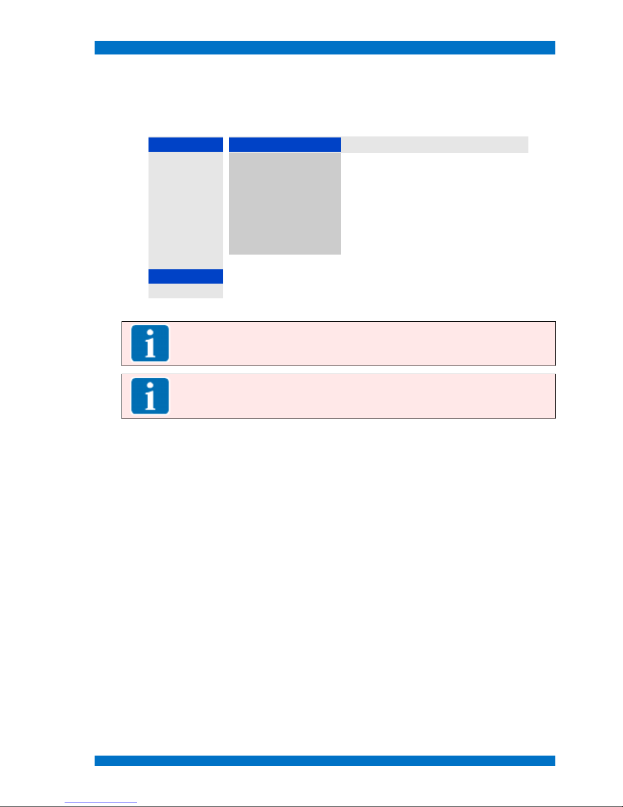
Main Menu SPARROWHAWK
Submenu Backlight
Select the BACKLIGHT MENU from the SYSTEMS MENU with the UP and DOWN keys and open the menu
step with the PLUS (V+) key.
The BACKLIGHT MENU shows following operational steps:
SYSTEM Backlight Setup
Help
Power On
2
Min. brightness 5.10 V defines the maximal voltage for the backlight
Search
2
Max. brightness 0.00 V defines the minimal voltage for the backlight
Processing
2
Steps 127 defines the number steps to control the backlight
Language
2
On/Off Control Pos selects the edge to switch the backlight ON or OFF
OSD
2
DPMS value 0.00 V defines the voltage for the DPMS
Wall
2
Default values
resets all settings back to default values
RGB Adjust
2
Backlight 48 shows the current backlight setting
Auto Color
2
Backlight
2
Anti Sticking
2
Note: This menu is normally hidden and for service purposes only. Do not use to modify for
your individual use. For more details see the service section of this manual.
Note: Adjusting the number of steps (default is 127 steps) for the backlight control, the
backlight dimming becomes more smooth.
Close and save this menu step by pushing the MENU key once.
© 02.07 TAMUZ - LCD Video Monitors LSM Digital Broadcast Monitor Page - 86 -

Main Menu SPARROWHAWK
Submenu Anti Sticking
The apparent „burning-in“ of pictures, the so called image sticking effect, of LCDs is undesirable but
can occur if the display is addressed with the same content over a long time period.
Here you see a monitor with a so called „burned-in“ pattern. A formerly
displayed grid with hard contrast and sharp edges sticks and overlays as a
ghost image to the color bars.
Unlike phosphor-based displays such as CRTs and plasma flat panels, LCD displays do not suffer
from permanent image burn-in resulting from the prolonged display of static images. This is widely understood as one of the key technological advantages of LCDs. However, a temporary retained image
may result in such displays, if a static image is displayed for a long time. This effect is not a degradation in overall life and does not appear in typical usage.
However, image sticking can occur and can be considered undesirable in certain applications where
24/7 display of static images is required. Every panel specification from every LCD manufacturer
usually includes language about "image sticking." As such, we believe the phenomenon is common to
all manufacturers.
How to minimize the effect?
In general, we can't promise that there is NO sticking effect within the TAMUZ LCD monitors.
The visibility of the effect depends on the LCD panel technology and most on the signal content itself.
In case of real video images with mostly continuously animated content the risk of a „burned-in“
image is low.
When static signals are displayed, for example feeds from a MultiViewer System or a graphic workstation, the risk to burn this type of content increases. But don't worry for short time periods. The sticking
effect appears only at longer influence.
If you use the monitor in an application where often static images will be displayed continuously, try to
use the asynchron mode, see menu SYSTEM – PROCESSING. This mode drives the LCD panel in a asynchronous mode, what means that the displayed vertical frequency is not corresponding with the input
video. The monitor operates within his native vertical frequency. F.e. a 50 Hz video becomes transformed in to a 62 Hz signal and formerly smooth moving items of the displayed footage becomes a little
jerky.
To avoid the image sticking and allow 365 days 24 hours operation, TAMUZ SPARROWHAWK series monitors have an user selectable „Anti-Sticking“ feature within their internal firmware. Using the
hidden service OSD menu this feature is accessible and programmable.
© 02.07 TAMUZ - LCD Video Monitors LSM Digital Broadcast Monitor Page - 87 -

Main Menu SPARROWHAWK
S
elect the ANTI STICKING MENU from the SYSTEMS MENU with the UP and DOWN keys and open the me-
nu step with the PLUS (V+) key.
The ANTI STICKING MENU shows following operational steps:
SYSTEM Anti Sticking
Help
Power On
2
Mode Invers defines what pattern will be displayed when enabled
Search
2
Periode Off defines the flashing period between 5s up to 12 h
Processing
2
Duration Off defines the duration of the flashing pattern
Language
2
Off ...
enables the emergency OFF for the Anti Sticking item
OSD
2
Active 0:00:48 shows the duration Anti Sticking take place
Wall
2
Rotation On enables a pixel rotation mode between 5s up to 12 h
RGB Adjust
2
Pixel 2 defines the movement of the pixel rotation
Auto Color
2
Backlight
2
Anti Sticking
2
Note: This menu is normally hidden and for service purposes only. Do not use to modify for
your individual use. For more details see the service section of this manual.
Note: Every customer or user of LCD monitors must be knowledgeable to this information.
Image sticking or burned-in at LCDs isn't subject to the customer service of the manufacturer
and doesn't obtain a claim of guarantee.
Close and save this menu step by pushing the MENU key once.
© 02.07 TAMUZ - LCD Video Monitors LSM Digital Broadcast Monitor Page - 88 -

Service Menu SPARROWHAWK
Service Menu
Opens the SERVICE MENU by pushing the MINUS key when no OSD menu is visible on screen.
When the menu did not open, it is hidden. Please ask your administrator to open the hidden menu
section with the correct password.
Note: This menu is normally hidden and for service purposes only. Don't use to modify for
your individual use. For more details see the service section of this manual.
The SERVICE MENU shows following operational or informational steps:
SERVICE
Help
Info
2
information about the interface and firmware
MTBFs
2
opens the sub menu MAINTENANCE for the backlight
Setup
2
opens the sub menu SETUP
Firmware
2
opens the sub menu FIRMWARE
Note: This menu is normally hidden and for service purposes only. Don't use to modify for
your individual use. For more details see the service section of this manual.
Close and save this menu step by pushing the MENU key once.
© 02.07 TAMUZ - LCD Video Monitors LSM Digital Broadcast Monitor Page - 89 -

Service Menu SPARROWHAWK
Submenu Info
Select the INFO MENU from the SYSTEMS MENU with the UP and DOWN keys and open the menu step
with the PLUS (V+) key.
The INFO MENU shows following operational steps:
SERVICE Info
Help
Info
2
Interface EAGLE shows the version of the monitors interface board
MTBFs
2
Display 0x25B shows the type code of the monitors TFT panel
Setup
2
Firmware 5.060 shows the revision of the firmware
Firmware
2
Date 06.11.06 shows the date of the firmware
Clock 82.05 shows the panel clock frequency.
Panel H 53.14 shows the horizontal frequency.
Panel V 62.50 shows the vertical frequency.
Note: This menu is normally hidden and for service purposes only. Don't use to modify for
your individual use.
Close and save this menu step by pushing the MENU key once.
© 02.07 TAMUZ - LCD Video Monitors LSM Digital Broadcast Monitor Page - 90 -

Service Menu SPARROWHAWK
Submenu MTBFs
Select the MTBFs MENU from the SYSTEMS MENU with the UP and DOWN keys and open the menu step
with the PLUS (V+) key.
The MTBFs MENU shows following operational steps:
SERVICE Info
Help
Info
2
Backlight MTBF 10000 shows the mean time between failure for the
backlight
Note: SPARROWHAWK series monitors will be
equipped with backlight systems which have a MTBF
of minimum 10.000 hours.
MTBFs
2
Backlight reset
resets the counted operation time to zero MTBF value
Setup
2
IR-Access code 0 enables and selects the Infrared Remote access
code. (The default value is 0)
Firmware
2
IR locked
disables the IR remote port
Reset
reset the monitor to factory default settings
Note: This menu is normally hidden and for service purposes only. Don't use to modify for
your individual use.
Close and save this menu step by pushing the MENU key once.
© 02.07 TAMUZ - LCD Video Monitors LSM Digital Broadcast Monitor Page - 91 -

Service Menu SPARROWHAWK
Submenu Setup
Select the SETUP MENU from the SYSTEMS MENU with the UP and DOWN keys and open the menu step
with the PLUS (V+) key.
The SETUP MENU shows following operational steps:
SERVICE Setup
Help
Info
2
No signal
2
opens the sub menu NO SIGNAL
MTBFs
2
Temperatures
2
opens the sub menu TEMPERATURES
Setup
2
Aux1 I/O
2
opens the sub menu AUXILIARY 1
Firmware
2
Aux2 I/O
2
opens the sub menu AUXILIARY 2
Aux3 I/O
2
opens the sub menu AUXILIARY 3
Backlight
2
enables the adjustment for the backlight
Note: This menu is normally hidden and for service purposes only. Don't use to modify for
your individual use.
Close and save this menu step by pushing the MENU key once.
© 02.07 TAMUZ - LCD Video Monitors LSM Digital Broadcast Monitor Page - 92 -

Service Menu SPARROWHAWK
Submenu No Signal
Select the NO SIGNAL MENU from the SYSTEMS MENU with the UP and DOWN keys and open the menu
step with the PLUS (V+) key.
The SPARROWHAWK series monitors are equipped with a dynamic power management system.
Therewith it is possible to suspend the backlight when no signal is available at the input. Setup a time
to wait before the system dims the light down.
A second time window sets the waiting before the system shuts down at no signal.
The NO SIGNAL MENU shows following operational steps:
Setup No Signal
Help
No signal
2
DPMS
2
opens the sub menu DPMS (Dynamic Power
Management System) to select the suspend and
power down times
Temperatures
2
Blue
enables a blue background on screen at no signal
Aux1 I/O
2
Black
enables a black background on screen at no signal
Aux2 I/O
2
User
enables a individual colored background on screen
at no signale
Aux3 I/O
2
Text
enables TEXT messages at no signale
Backlight
2
Note: This menu is normally hidden and for service purposes only. Don't use to modify for
your individual use.
Close and save this menu step by pushing the MENU key once.
© 02.07 TAMUZ - LCD Video Monitors LSM Digital Broadcast Monitor Page - 93 -

Service Menu SPARROWHAWK
Submenu Temperatures
Select the TEMPERATURES MENU from the SYSTEMS MENU with the UP and DOWN keys and open the
menu step with the PLUS (V+) key.
The TEMPERATURES MENU shows following operational steps:
Setup Temperatures
Help
No signal
2
Current Temp. 60 °C shows the current temperature in the electronic
Temperatures
2
lowest -5 °C select the threshold for the lowest temperature
Aux1 I/O
2
highest 65 °C select the threshold for the highest temperature
Aux2 I/O
2
Backlight down
driving down the backlight if the system temperature
reaches one of the limits
Aux3 I/O
2
Backlight
2
Note: This menu is normally hidden and for service purposes only. Don't use to modify for
your individual use.
Close and save this menu step by pushing the MENU key once.
© 02.07 TAMUZ - LCD Video Monitors LSM Digital Broadcast Monitor Page - 94 -

Service Menu SPARROWHAWK
Submenu Aux1 Configuration
Select the AUX1 CONFIG MENU from the SYSTEMS MENU with the UP and DOWN keys and open the menu
step with the PLUS (V+) key.
The AUX1 CONFIG MENU shows following operational steps:
Setup Aux1 Configuration
Help
No signal
2
Input high
2
select the event for the AUX1 GPI/O remote port,
when the trigger pulse is high
Temperatures
2
Input low
2
select the event for the AUX1 GPI/O remote port,
when the trigger pulse is low
Aux1 I/O
2
Temperature 60 °C select the threshold for the temperature to trigger the
AUX1 as an alarm to be used for switching external
devices
Aux2 I/O
2
Aux3 I/O
2
Backlight
2
Note: This menu is normally hidden and for service purposes only. Don't use to modify for
your individual use.
Close and save this menu step by pushing the MENU key once.
© 02.07 TAMUZ - LCD Video Monitors LSM Digital Broadcast Monitor Page - 95 -

Service Menu SPARROWHAWK
Submenu Aux2 Configuration
Select the AUX2 CONFIG MENU from the SYSTEMS MENU with the UP and DOWN keys and open the menu
step with the PLUS (V+) key.
The AUX2 CONFIG MENU shows following operational steps:
Setup Aux2 Configuration
Help
No signal
2
No Function
disables the AUX2 I/O feature
Temperatures
2
Over/Under temp.
enables the AUX2 I/O feature to trigger the AUX2 as
an alarm when the current measured temperature is
over or under the set threshold value. This can be
used for switching external devices
Aux1 I/O
2
On above temp.
enables the AUX2 I/O feature to trigger the AUX2 as
an alarm when the current measured temperature is
above the set threshold value. This can be used for
switching external devices
Aux2 I/O
2
On below temp.
enables the AUX2 I/O feature to trigger the AUX2 as
an alarm when the current measured temperature is
below the set threshold value. This can be used for
switching external devices
Aux3 I/O
2
Temperature 60 °C select the threshold for the temperature to trigger the
AUX1 as an alarm to be used for switching external
devices
Backlight
2
Note: This menu is normally hidden and for service purposes only. Don't use to modify for
your individual use.
Close and save this menu step by pushing the MENU key once.
© 02.07 TAMUZ - LCD Video Monitors LSM Digital Broadcast Monitor Page - 96 -
Service Menu SPARROWHAWK
Submenu Aux3 Configuration
Select the AUX3 CONFIG MENU from the SYSTEMS MENU with the UP and DOWN keys and open the menu
step with the PLUS (V+) key.
The AUX3 CONFIG MENU shows following operational steps:
Setup Aux3 Configuration
Help
No signal
2
0V Temperature -5 °C select the threshold for the temperature to trigger the
AUX3 as an LOW alarm to be used for switching
external devices
Temperatures
2
5V Temperature 65 °C select the threshold for the temperature to trigger the
AUX3 as an HIGH alarm to be used for switching
external devices
Aux1 I/O
2
Aux2 I/O
2
Aux3 I/O
2
Backlight
2
Note: This menu is normally hidden and for service purposes only. Don't use to modify for
your individual use.
Close and save this menu step by pushing the MENU key once.
© 02.07 TAMUZ - LCD Video Monitors LSM Digital Broadcast Monitor Page - 97 -

Service Menu SPARROWHAWK
Submenu Backlight
Select the AUX3 CONFIG MENU from the SYSTEMS MENU with the UP and DOWN keys and open the menu
step with the PLUS (V+) key.
The AUX3 CONFIG MENU shows following operational steps:
Setup Auto Backlight
Help
No signal
2
Auto
enables this feature for automatic operation
Temperatures
2
Min. Brightness 4.00 V select the sensor value for minimum brightness
Aux1 I/O
2
Max. Brightness 0.00 V select the sensor value for maximum brightness
Aux2 I/O
2
Sensor value 1.44 V indicates the current sensor voltage value
Aux3 I/O
2
Backlight 15 indicates the current backlight value
Backlight
2
Note: This menu is normally hidden and for service purposes only. Don't use to modify for
your individual use.
Close and save this menu step by pushing the MENU key once.
© 02.07 TAMUZ - LCD Video Monitors LSM Digital Broadcast Monitor Page - 98 -

Service Menu SPARROWHAWK
Submenu Firmware
Select the FIRMWARE MENU from the SYSTEMS MENU with the UP and DOWN keys and open the menu
step with the PLUS (V+) key.
The FIRMWARE MENU shows following operational steps:
SERVICE Firmware
Help
Info
2
Baudrate 115.2 k shows the the transmission speed for a download via
the serial interface port
MTBFs
2
Download
enables the download of firmware into the EPROM
Setup
2
Transmitted 0 shows the downloaded number of bytes
Firmware
2
Byte Errors 0 shows errors during the firmware download
Status Idle shows the STATUS of the firmware download process
Note: This menu is normally hidden and for service purposes only. Don't use to modify for
your individual use.
Close and save this menu step by pushing the MENU key once.
© 02.07 TAMUZ - LCD Video Monitors LSM Digital Broadcast Monitor Page - 99 -

Individual Adjustments and Setups SPARROWHAWK
Individual Adjustments and Setups
Aspect Ratio Setup
The SPARROWHAWK monitor series is capable for standard computer graphic and TV wide screen
16:9 and normal screen 4:3 aspect ratio images. Therefore the selection is easily done by the switch
FORMAT.
Other wide screen aspect ratios are adjustable to display a full or approximately full screen image.
Video Aspect Ratio Film Aspect Ratio Geometry - Input - Lines Geometry - Input - Samples
4 : 3 1 : 1,33333 576 940
16 : 9 1 : 1,77777 576 940
16 : 8,65 1 : 1,85 554 940
16 : 7,24 1 : 2,21 464 940
16 : 6,80 1 : 2,35 434 940
To adjust an individual aspect ratio, open the menu GEOMETRY - SETTINGS - INPUT with the IR remote
controller and select a new value for the sampled lines. This changes the horizontal to vertical ratio.
Best results will be found, when the displayed image shows a circular parts.
Setup Instructions
The SPARROWHAWK monitor series interface is capable for several input signals. To present the signal at its best use the default setup or re-adjust, see tables below.
Setup VGA Signals
Computer Graphic Signals (called VGA) at the VGA input ports:
Signal Format Aspect Ratio
Pixel Clock /
MHz
Phase X-Position Y-Position Pixel Lines Interlace
MGA 4 : 3 720 350 no
Hercules 4 : 3 720 350
CGA 4 : 3 640 200 no
EGA 4 : 3 640 350 no
VGA 4 : 3 25.16 31 -31 -10 640 480 No
SVGA 4 : 3 39.34 19 -33 -8 800 600 No
W-SVGA 17 : 10 1024 600
XGA 4 : 3 64.65 17 -43 -9 1024 768 No
W-XGA 15 : 9 1280 768
HD 720 16 : 9 1280 720
Mac 4 : 3 1152 870
SXGA 5 : 4 108.05 30 2 -16 1280 1024 No
W-SXGA 16 : 10 1600 1024
UXGA 4 : 3 1600 1200
W-UXGA 16 : 10 1920 1200
HD 1080 16 ; 9 1920 1080
QXGA 4 : 3 2048 1536
© 02.07 TAMUZ - LCD Video Monitors LSM Digital Broadcast Monitor Page - 100 -
 Loading...