

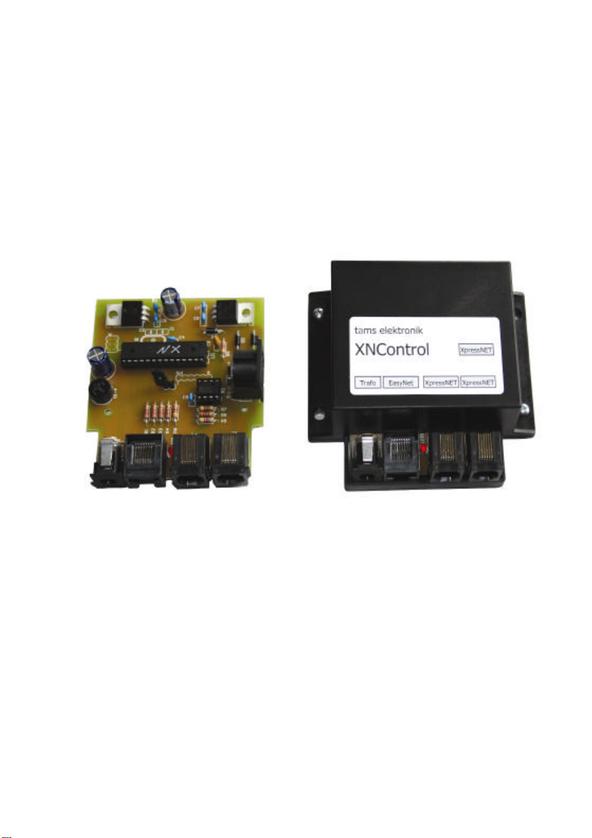
XNControl
XpressNET adapter for
digital control EasyControl
Item no. 40-01305 (kit) / 40-01307 (ready-built device)
Manual
Information and tips:
www . tams-online.de
n
n
n
n
n
n
n
n
n
n
n
Warranty and service:
Tams Elektronik GmbH
Rupsteinstraße 10
D-30625 Hannover
fon: +49 (0)511 / 55 60 60
fax: +49 (0)511 / 55 61 61
e-mail: modellbahn@tams-online.de
© 06/2008 Tams Elektronik GmbH
All rights reserved. No part of this publication
may be reproduced or transmitted in any
form or by any means, electronic or
mechanical, including photocopying, without
prior permission in writing from Tams
Elektronik GmbH.
Subject to technical modification.
n
The asterisks **
n
This manual mentions the following
companies:
n
LENZ** Elektronik GmbH
Hüttenbergstraße 29
n
D-35398 Gießen
n
ROCO
Modelleisenbahn GmbH
Plainbachstraße 4
n
A-5101 Bergheim
n
n
n
n
n

XNControl English
Table of contents
1. What for is XNControl? 3
2. Getting started 3
3. Safety instructions 4
4. Safe and correct soldering 6
5. Assembling the kit 7
6. Connecting the XNControl 11
7. Operation with the XNControl 12
8. Software Update 12
9. Technical specifications 13
10. Manufacturer's note, CE and Warranty 13
1. What for is XNControl?
The XNControl is an adapter to connect up to 16 XpressNET control devices to the digital model
railway controller EasyControl. Examples for XpressNET control devices are:
Lokmaus 2, Lokmaus 3 (not Lokmaus 1) and Multimaus from Roco**
Hand controller from Lenz**
Connecting the XpressNET control devices to the XNControl allows you to use them as hand
control devices in the digital controller EasyControl. The XNControl receives the control and switch
commands sent from the XpressNET control devices via the data bus XpressNET, translates them
into control and switch commands for the databus EasyNet used by the digital system EasyControl
and passes them on to the central unit MasterControl. This sends the commands to the various
decoders (locomotive, function, points or switching decoders) on your layout.
It is impossible to access from XpressNET control device data in the locomotive database of the
MasterControl, to change the data or to program decoders. A PC planed to be integrated into the
digital control EasyControl has to be connected directly to the MasterControl as XpressNet PC
interfaces are not supported by the XNControl.
2. Getting started
How to use this manual
This manual gives step-by-step instructions for safe and correct assembly of the kit and
connecting of the ready-built device, and operation. Before you start, we advise you to read the
whole manual, particularly the chapter on safety instructions and the FAQ chapter. You will then
know where to take care and how to prevent mistakes which take a lot of effort to correct.
Keep this manual safely so that you can solve problems in the future. If you pass the kit or the
ready-built device on to another person, please pass on the manual with it.
Page 3

English XNControl
Intended use
The XNControl has been designed for connection to the digital control EasyControl in concordance
with these instructions. The kit and the ready-built device should not be assembled or fitted by
children under the age of 14. Any other use is inappropriate and invalidates any guarantees.
Reading, understanding and following the instructions in this manual are mandatory for the user.
Checking the package contents
Please make sure that your package contains:
§ one kit, containing the components listed in the parts and one PCB or one XNControl,
§ patch-cable (RJ45) for connecting the XNControl to the MasterControl,
§ one jumper for use with software update
§ one manual.
Required materials
For assembling the kit you need:
§ an electronic soldering iron (max. 30 Watt) with a fine tip,
§ a soldering iron stand,
§ a tip-cleaning sponge,
§ a heat-resistant mat,
§ a small side cutter and wire stripper,
§ a pair of tweezers and long nose pliers,
§ tin solder (0,5 mm. diameter).
For the power supply of the connected XpressNET devices you will need:
§ AC or DC power pack with 12 V and min. 1A current, e.g. AC power pack item-no. 79-10026
from Tams Elektronik (not included in delivery).
3. Safety instructions
Mechanical hazards
Cut wires can have sharp ends and can cause serious injuries. Watch out for sharp edges when
you pick up the PCB.
Visibly damaged parts can cause unpredictable danger. Do not use damaged parts: recycle and
replace them with new ones.
Electrical hazards
§ Touching powered, live components,
§ touching conducting components which are live due to malfunction,
§ short circuits,
§ connecting the circuit to another voltage than specified,
§ impermissibly high humidity,
§ condensation build up
can cause serious injury due to electrical shock. Take the following precautions to prevent this
danger:
§ Never perform wiring on a powered device.
§ Assembling and mounting the kit should only be done in closed, clean, dry rooms. Beware of
humidity.
Page 4

XNControl English
§ Only use low power for this device as described in this manual and only use certified
transformers.
§ Connect transformers and soldering irons only in approved mains sockets installed by an
authorised electrician.
§ Observe cable diameter requirements.
§ After condensation build up, allow a minimum of 2 hours for dispersion.
§ Use only original spare parts if you have to repair the kit or the ready-built device.
Fire risk
Touching flammable material with a hot soldering iron can cause fire, which can result in injury or
death through burns or suffocation. Connect your soldering iron or soldering station only when
actually needed. Always keep the soldering iron away from inflammable materials. Use a suitable
soldering iron stand. Never leave a hot soldering iron or station unattended.
Thermal danger
A hot soldering iron or liquid solder accidentally touching your skin can cause skin burns. As a
precaution:
§ use a heat-resistant mat during soldering,
§ always put the hot soldering iron in the soldering iron stand,
§ point the soldering iron tip carefully when soldering, and
§ remove liquid solder with a thick wet rag or wet sponge from the soldering tip.
Dangerous environments
A working area that is too small or cramped is unsuitable and can cause accidents, fires and
injury. Prevent this by working in a clean, dry room with enough freedom of movement.
Other dangers
Children can cause any of the accidents mentioned above because they are inattentive and not
responsible enough. Children under the age of 14 should not be allowed to work with this kit or the
ready-built device.
Little children can swallow small components with sharp edges, with fatal results! Do not allow
components to reach small children.
In schools, training centres, clubs and workshops, assembly must be supervised by qualified
personnel.
In industrial institutions, health and safety regulations applying to electronic work must be
adhered to.
Page 5

English XNControl
!
4. Safe and correct soldering
Caution:
Incorrect soldering can cause dangers through fires and heat. Avoid these dangers by reading and
following the directions given in the chapter Safety instructions. If you have had training in
soldering you can skip this chapter.
§ Use a small soldering iron with max. 30 Watt. Keep the soldering tip clean so the heat of the
soldering iron is applied to the solder point effectively.
§ Only use electronic tin solder with flux.
§ When soldering electronic circuits never use soldering-water or soldering grease. They contain
acids that can corrode components and copper tracks.
§ Solder quickly: holding the iron on the joints longer than necessary can destroy components
and can damage copper tracks or soldering eyes.
§ Observe correct polarity orientation of semi-conductors, LEDs electrolytic capacitors and
integrated circuits before soldering and ensure that the solder time does not exceed 5
seconds, otherwise components can be damaged.
§ Apply the soldering tip to the soldering spot in such a way that the part and the soldering eye
are heated at the same time. Simultaneously add solder (not too much). As soon as the solder
becomes liquid take it away. Hold the soldering tip at the spot for a few seconds so that the
solder flows into the joint, then remove the soldering iron.
§ Do not move the component for about 5 seconds after soldering.
§ To make a good soldering joint you must use a clean and unoxidised soldering tip. Clean the
soldering tip with a damp piece of cloth, a damp sponge or a piece of silicon cloth.
§ Cut the wires after soldering directly above the PCB solder side with a side cutter.
§ After placing the parts, please double check for correct polarity. Check the PCB tracks for
solder bridges and short circuits created by accident. This would cause faulty operation or, in
the worst case, damage. You can remove excess solder by putting a clean soldering tip on the
spot. The solder will become liquid again and flow from the soldering spot to the soldering tip.
Page 6

XNControl English
5. Assembling the kit
You can skip this part if you have purchased a ready-built device.
Preparation
Put the sorted components in front of you on your workbench. The separate electronic
components have the following special features you should take into account to prevent mistakes
in assembling:
Resistors
Resistors reduce current. Their mounting orientation is of no importance. The value of
resistors for smaller power ratings (under 5 W) is indicated through colour rings. Every
colour stands for another figure. The colour ring in brackets indicates the tolerance of
the resistor which here is of no importance.
Value Colour rings
120 Ω brown - red - brown (gold)
4,7 kΩ yellow - violet - red (gold)
Diodes
Diodes allow the current to pass through in one direction only (forward direction),
simultaneously the voltage is reduced by 0,3 to 0,8 V. Exceeding of the limit voltage always
will damage the diode, and allow current to flow in the reverse direction.
The diode type is printed on the body.
Diodes must be mounted in a given direction. The negative end is marked with a ring.
This is shown in the PCB layout.
Light emitting diodes (LEDs)
When operated in the forward direction the LEDs light. They are available in several
different versions (differing in colour, size, form, luminosity, maximum current, voltage
limits). The longer lead of wired LEDs is always the anode (positive pole).
Capacitors
Among other things capacitors are used for filtering interference voltages or as frequency
determining parts. Ceramic capacitors are not polarized, for that reason their mounting
orientation is of no importance. Normally they are marked with a three-digit number which
indicates the value coded.
Value Number
10 nF 103
100 nF 104
Page 7

English XNControl
Electrolytic capacitors
Electrolytic capacitors are often used to store energy. In contrast to ceramic capacitors
they are polarized. One of the two leads is marked with a minus sign which indicates the
mounting orientation. The value is given on the casing.
Electrolytic capacitors are available with different voltage sustaining capabilities. Using an
electrolytic capacitor with a voltage sustaining capability higher than required is always
possible.
Rectifiers
Rectifiers convert alternating into direct voltage, they have hardly no influence on the
level of the voltage. They have four pins: two for the input voltage (a.c. voltage) and
two for the output voltage (d.c. voltage). The pins for the output voltage are polarized.
The pin connections are printed on the housing. As usual with wired components the
longer connecting pin is the positive pole.
Integrated circuits (ICs)
Depending on the type, ICs fulfil various tasks. They are polarized and therefore have to
be mounted in a certain direction. The most common housing form is the so-called
"DIL"-housing, from which 4, 6, 8, 14, 16, 18 or more "legs" (pins) are arranged along
the long sides. The mounting orientation is shown by a semicircular or circular marking
at the end of the housing, which is also shown on the PCB layout.
ICs are sensitive to damage during soldering (heat, electrostatic charging). For that
reason in the place of the ICs IC sockets are soldered in, in which the ICs are inserted
later. The mounting orientation of the sockets is preset as well. The markings on the
PCB, the socket and the IC must lie on top of each other after mounting.
Micro-Controler
Micro-controller are ICs, which are individually programmed for the particular
application. When leaving the manufacturer´s works their memory is empty. The
programmed controller normally are only available from the manufacturer of the circuit
belonging to it.
Voltage regulators
Voltage regulators are ICs, which convert a variable, non regulated input voltage in a
constant output voltage. They are produced in transistor housings with three connecting
pins for input, output and earth.
With voltage regulators in a SOT-housing (in form of a half cylinder) the mounting
orientation is given by the layout of the connecting pins.
With voltage reuglators in a flat TO-housing the unlabelled metallic rear is marked by a
thick line on the PCB layout.
Page 8

XNControl English
Parts list
Resistors R1, R2, R3, R4, R5 120 Ω
R6, R7, R8, R9 4,7 kΩ
Diodes D1, D2, D3 1N4004
LEDs LED1 3 mm
Capacitors C1, C2 not inserted
C3 10 nF
C4, C5, C6, C7, C8, C9 100 nF
Electrolytic capacitors C10, C11 470µF
Rectifiers D1-4 B80C800
Micro-Controller U1 MEGA 168
ICs U4 SN75176
IC-sockets for U1 28-pin
for U4 8- pin
Voltage regulators U2 7812
U3 7805
Quartz Q1 not inserted
Connecting socket J3 RJ 45 connecting socket
J4 not inserted
J5, J6 RJ 12 connecting socket
X1 5- pin DIN-socket
X2 power-socket
Pin-type strip JP1 2-pin
SV1 not inserted
PCB print
Page 9

English XNControl
!
!
Assembling the kit
Start the assembly with the the resistors and the diodes. First solder the components on the
solder side of the PCB and then cut the excess wires with the side cutter, as short as possible.
Next solder the pin-type strip, the IC-socket, the rectifier and the voltage regulator. If you intend
to mount the circuit into the housing supposed for the enclosure of the XNControl please follow
the instructions in the section "Enclosure of the XNControl".
Continue the assembly with the capacitors and the electrolytic capacitors. Last solder the
connecting socket and the LED.
Caution:
Diodes, IC-sockets, rectifiers, electrolytic capacitors, and LEDs must be placed in the right
direction! If you solder them the wrong way round the affected parts can be damaged when you
connect the power. In the worst case the whole circuit can be damaged. In any case, a wrongly
connected part will not function.
Finally, insert the ICs into the soldered IC-sockets.
Caution:
Do not touch the ICs without first discharging yourself by touching a radiator or other grounded
metal parts. Do not bend the "legs" of the ICs when inserting them into the sockets. Check that
the markings on the PCB, the socket and the IC show to the same direction.
Performing a visual check
Perform a visual check after the assembly of the device and remove faults if necessary:
§ Remove all loose parts, wire ends or drops of solder from the PCB. Remove all sharp wire
ends.
§ Check that solder contacts which are close to each other are not unintentionally connected to
each other. Risk of short circuit!
§ Check that all components are polarised correctly.
When you have remedied all faults, go on to the next part.
Enclosure of the XNControl
There is a housing avalaible for the XNControl (item no. 40-01308). If you intend to use this
housing the electrolytic voltage regulators U2 and U3 have to be bent by 90 degrees. Bend the
connecting wires before soldering in the regulators, as you otherwise might solder them in too
close to the PCB.
Page 10

XNControl English
!
6. Connecting the XNControl
Caution:
If a component gets hot or the LED does
not light disconnect the power pack
immediately from the power supply and
check the assembly. Risk of short circuit!
5
1 2 3 4
Connections of the XNControl
1 Power supply for up to
16 XpressNET devices
2 MasterControl or
BusControl connected in series
(RJ-45 connecting socket)
3 / 4 RJ-12 connecting socket e.g. for Lokmaus 2 and 3 or Multimaus from
5 5- pin DIN-socket e.g. for hand controller from Lenz**
Use an AC or DC powerpack with
12 to 16 Volt and min. 1 A current.
Any Ethernet patch cable (used in Computer
networks) will work for connection.
Roco**
Connecting several XpressNET control devices
You can connect two devices simultaneously with RJ12-connectors and one device with a 5-pin
DIN connector directly. Using a special distributor (additional accessory) allows to connect up to
16 XpressNET control devices.
Connecting several decentralised control devices or adapters
You may connect up to 64 decentralised control devices or adapters to one EasyNet. If you intend
to connect more than one control device you will also need:
§ up two control devices: a distributor BusControl (optional extra). The BusControl is sufficient
to control max. nine control devices. If you intend to connect further devices you need
additional BusControls.
§ up five control devices: an additional AC power pack (optional extra). An additional AC Power
Pack is sufficient to supply eight further control devices. If you intend to connect further
devices you need additional power packs.
Also see the BusControl’s manual.
Page 11

English XNControl
7. Operation with the XNcontrol
Before you can send control and switching commands from a XpressNET device you have to make
the following connections:
§ XNControl – MasterControl
§ XNControl – power supply
§ XpressNET device – XNControl
Enter the control and switching commands according to the instructions for the XpressNET device.
The LED on the XNControl flashes irregularly while receiving data, translating and sending it to the
MasterControl.
Please note: Neither is it possible to enter the MasterControl database from a connected
XpressNET device or to alter data nor to program a decoder from a connected XpressNET device.
8. Software Update
Your XNControl is a state-of-the-art product, which is constantly improved and adapted to
occurring changes. To benefit from this development, you can update the MasterControl to the
newest software version.
Diconnect all external control devices from the EasyNet – including the XNControl you want to
update.
Unsrew the cover from the housing. Then bypass the two pins of the pin-type strip JP1 at the
XNControl (e.g. with the added jumper) and restore the connection from XNControl to the
EasyNet. The LED on the XNControl starts to flash quickly.
Next select the menu point "Software Update" at your MasterControl and confirm your input with
# / ok. Now the LED on the XNControl flashes slower and regularly. The MasterControl will then
display in the second line "...Download..."
Now please connect the MasterControl to your PC and execute the update application.
Please note: Always connect the MasterControl to your PC before executing the update
application. Otherwise your PC might have difficulties detecting the interface.
Follow the instructions of the update application.
Page 12

XNControl English
9. Technical Specifications
Power supply for XpressNET devices: AC or DC power pack 12-16 V / min. 1 A
Power supply for XNControl: AC or DC power pack 12-16 V / min. 1 A
or via EasyNet (for software update only)
Power consumption (without consumer): approx. 100 mA
Interfaces: EasyNet (RJ-45)
XpressNET (RJ-12 und DIN 5-polig)
Protection: IP 00
Ambient temperature while operating: 0 - + 60 °C
Ambient temperature while not operating: -10 bis + 80 °C
Maximum humidity: max. 85 %
Dimensions (including housing) approx. 100 x 90 x 35 mm
Weight of the circuit approx 42,1 g
Weight including housing approx 96,1 g
10. Manufacturer's note, CE and Warranty
Manufacturer's note
The person who builds this kit or brings the circuit into operation is the manufacturer of the
product. If he sells the product to another person he is responsible for passing on all the relevant
papers. Domestic appliances assembled from a kit are deemed industrial products and must
comply with health and safety regulations.
Certification
This product is developed and tested in accordance with the European standards EN 55014-1 and
EN 61000-6-3. This product conforms with the EC- directive 2004/108/EG on electromagnetic
radiation and is therefore CE certified.
To guarantee the electromagnetic tolerance in operation you must take the following precautions:
§ Connect the transformer only to an approved mains socket installed by an authorised
electrician.
§ Make no changes to the original parts and accurately follow the instructions, circuit diagram
and PCB layout included with this manual.
§ Use only original spare parts if you have to repair the kit or the ready-built device.
Conditions of warranty
This product is guaranteed for two years. The warranty includes the correction of faults which can
be proved to be due to material failure or factory flaw. As we have no control over the correct and
proper assembly and mounting we can only guarantee the quality of the components and the
completeness of kits. We guarantee the function of the parts according to the parameters in not
mounted state as well as the adherence to the technical specifications of the circuit when
assembled and connected according to the manual.
Other claims are excluded. By law, we are not responsible for damages or secondary damages in
connection with this product. We retain the right to repair, make improvements, supply spare
parts or return the purchase price.
Page 13

English XNControl
The following invalidate the warranty:
§ using an unsuitable soldering iron, solder containing liquid acids or similar,
§ if the kit is assembled and soldered poorly, or if damage is caused by not following the
instructions in this manual,
§ if the ready-built device has been altered and repair attempts have failed,
§ if arbitrary changes in the circuit are made,
§ if components are removed or swapped, or wiring is added or removed in any other way as
layed down in the original design,
§ if parts other than the originals delivered with this kit are used,
§ if the copper tracks or soldering eyes are damaged,
§ when components are mounted incorrectly, or if the components or the circuit are poled
incorrectly, also subsequent damage resulting from these faults,
§ if damage occurs due to an overload of the device,
§ if connected to a incorrect voltage or current,
§ if damaged by other persons,
§ if damaged by faulty operation or if damaged by careless use or abuse,
§ if damaged by touching components before electrostatic discharging of the hands.
Page 14
 Loading...