

Manual
Locomotive decoders
series 30
plus
LD-G-31
plus
Item 41-03310
Item 41-03312
Item 41-03313
LD-G-33
plus
Item 41-03330
Item 41-03332
Item 41-03333
Item 41-03334
LD-G-34
plus
Item 41-03340
Item 41-03341
Item 41-03342
LD-G-36
plus
Item 41-03360x
Item 41-03362x
Item 41-03363x
Item 41-03364x
tams elektronik
n n n
DCC MM

English Locomotive decoders of the series 30 plus
Contents
1. Getting started............................................................................6
2. Safety instructions.......................................................................9
3. Safe and correct soldering.........................................................12
4. Operation overview...................................................................13
4.1. Modes of operation............................................................13
4.2. Driving of the motor..........................................................15
4.3. Function outputs...............................................................17
4.4. Sound functions................................................................18
4.5. Releasing the functions......................................................20
4.6. Automated processes.........................................................21
4.7. Feedback with RailCom** and RailCom plus **...................23
4.8. Overload protection (except LD-G-31 plus).........................24
4.9. POM-update (except LD-G-36 plus)....................................25
5. Technical specifications..............................................................26
6. Connections..............................................................................29
6.1. Connector pin assignment LD-G-31 plus (PluX12)................30
6.2. Connector pin assignment LD-G-33 plus (PluX22)................32
6.3. Connector pin assignment LD-G-33 plus (21MTC, 21-pole)...34
6.4. Connector pin assignment LD-G-34 plus..............................36
6.5. Connector pin assignment LD-G-36 plus (PluX22)................38
6.6. Connector pin assignment LD-G-36 plus (21MTC, 21-pole)...40
6.7. Using decoders with interface connectors...........................43
6.8. Use in locomotives with a.c. motor.....................................44
6.9. INFO: Earth connections and voltage outputs......................45
6.10.Mounting decoders without interface..................................46
6.11.Connecting LEDs to the function outputs............................48
6.12.Connecting inductive loads.................................................50
Page 2

Locomotive decoders of the series 30 plus English
6.13.Connecting accessories via a relay......................................50
6.14.Connecting a loudspeaker..................................................51
6.15.Connecting a buffer capacitor.............................................51
6.16.Connecting a servo (not with LD-G-31)...............................52
6.17.Connecting the switching inputs.........................................53
6.18.Connecting a SUSI module (except LD-G-31 plus)...............55
6.19.Connecting a clock generator to the LD-G-36 plus...............55
6.20.Fixing the decoder.............................................................55
7. Programming............................................................................56
8. Configuration variables and registers..........................................59
9. Performing a POM-Update.........................................................82
10. Check list for troubleshooting.....................................................84
11. Guarantee bond........................................................................88
12. EU declaration of conformity......................................................89
13. Declarations conforming to the WEEE directive...........................89
© 11/2015 Tams Elektronik GmbH
All rights reserved. No part of this publication may be reproduced or
transmitted in any form or by any means, electronic or mechanical,
including photocopying, without prior permission in writing from Tams
Elektronik GmbH.
Subject to technical modification.
Page 3

English Locomotive decoders of the series 30 plus
The asterisks **
RailCom® is the registered trademark of:
Lenz Elektronik GmbH | Vogelsang 14 | DE-35398 Gießen
RailComPlus® is the registered trademark of:
Lenz Elektronik GmbH | Vogelsang 14 | DE-35398 Gießen and
ESU electronic solutions ulm GmbH & Co. KG | Edisonallee 29 |
DE-89231 Neu-Ulm
To increase the text´s readability we have refrained from refering to
this point in each instance.
This manual mentions the following companies:
Gebr. MÄRKLIN & Cie. GmbH | Stuttgarter Str. 55-57 |DE-73033 Göppingen
Uhlenbrock Elektronik GmbH | Mercatorstraße 6 | DE-46244 Bottrop
Page 4

Locomotive decoders of the series 30 plus English
1. Getting started
This manual applies to all locomotive decoders of the series 30 plus, so
for:
locomotive decoder LD-G-31 plus,
locomotive decoder LD-G-33 plus,
locomotive decoder LD-G-34 plus,
sound locomotive decoder LD-G-36 plus.
Provided there are no other details given for particular sections, the
information given applies to all decoders.
How to use this manual
This manual gives step-by-step instructions for safe and correct fitting and
connecting of the decoder, and operation. Before you start, we advise you
to read the whole manual, particularly the chapter on safety instructions
and the checklist for trouble shooting. You will then know where to take
care and how to prevent mistakes which take a lot of effort to correct.
Keep this manual safely so that you can solve problems in the future. If
you pass the decoder on to another person, please pass on the manual
with it.
Intended use
The locomotive decoders of the series 30 plus are designed to be
operated according to the instructions in this manual in model building,
especially in digital model railroad layouts. Any other use is
inappropriate and invalidates any guarantees.
The locomotive decoders should not be mounted by children under the
age of 14.
Reading, understanding and following the instructions in this manual
are mandatory for the user.
Page 5
English Locomotive decoders of the series 30 plus
Checking the package contents
Please make sure that your package contains:
one or five locomotive decoders, depending on the version with or
without soldered connecting wires resp. with or without interface
connector;
LD-G-31 plus: one or five buffer electrolytic capacitors (100 µF / 35 V);
LD-G-33 plus, LD-G-34 plus, LD-G-36 plus: one or five buffer
electrolytic capacitors (220 µF / 35 V);
LD-G-31 plus, LD-G-33 plus, LD-G-34 plus: one or five suppression
chokes (470 µH / >90mA);
a CD (containing the manual, Software "POM-Updater.exe" and
further information).
N.B. For technical reasons it is possible that the PCB is not completely
inserted. This is not a fault.
Available versions
Connecting wires /
Interface
LD-G-31
plus
LD-G-33
plus
LD-G-34
plus
LD-G-36
plus
without wires *
1
+ + + +
with wires *
1
– – + –
according to NEM 650*18-pole
(NEM 652)
8-pole
(NEM 652)
8-pole
(NEM 652)
8-pole
(NEM 652)
according to NEM 658 PluX12 PluX22 – PluX22
according to NEM 660 – 21MTC – 21MTC
similar to NEM 660 – 21-pole*
2
(4 amplified
outputs)
– 21-pole
(4 amplified
outputs)
*1 connections according to version with PluX interface
*2 in preparation (status 11/2015)
Page 6

Locomotive decoders of the series 30 plus English
Required materials
For mounting and connecting decoders without interface you need:
an electronic soldering iron (max. 30 Watt) or a regulated soldering
iron with a fine tip and a soldering iron stand,
a tip-cleaning sponge,
a heat-resistant mat,
a small side cutter, a wire stripper and a pair of tweezers,
electronic tin solder (0.5 mm diameter).
In order to connect decoders without interface or soldered connecting
wires you will need wire. Recommended cross sections:
> 0,04 mm² for the connections to the function outputs;
> 0,05 mm² for the connections to the motor and current collectors
(except for the LD-G-34 plus);
> 0,14 mm² for connections to the motor and current collectors of
the LD-G-34 plus.
For playing back the sounds you need:
a loudspeaker with an impedance of min. 4 Ohm and a rated load-
carrying capacity of min. 0,1 Watt.
If you want to trigger switching operations automatically, e.g.:
reed contacts 1 x closing contact (e.g. item-no. 84-53110) and / or
Hall-sensors (e.g. item-no. 84-53210) and
permanent magnets (e.g. neodymium magnets Ø 3mm, thickness =
2mm, item-no. 84-53990);
for the connection via the SUSI connector plug of the deocder: a
SUSI socket with wires (e.g. item no. 70-01111).
If you want to use the output for the servo:
one servo,
a voltage supply for the servo (e.g. servo PCB item-no. 70-05900).
Page 7

!
English Locomotive decoders of the series 30 plus
As a clock generator for the sound locomotive decoder LD-G-36 plus
(e.g. to control the correct syncronisation of the steam discharge with
the wheel movements):
reed contacts 1 x closing contact (e.g. item-no. 84-53110)
and / or Hall-sensors (e.g. item-no. 84-53210) and
permanent magnets (e.g. neodymium magnets Ø 3mm, thickness =
2mm, item-no. 84-53990).
If you want to connect the decoder to an a.c. motor:
a load control adapter LRA (item no. 70-02105 or 70-02106) or
a permanent magnet (e.g. item no. 70-04100, 70-04200 or 70-
04300) or
a motor modification set (e.g. item no. 70-40110, 70-40210 or
70-40310).
2. Safety instructions
Caution:
Integrated circuits (ICs) are inserted on the decoder. They are
sensitive to static electricity. Do not touch components without first
discharging yourself. Touching a radiator or other grounded metal part
will discharge you.
Mechanical hazards
Cut wires can have sharp ends and can cause serious injuries. Watch
out for sharp edges when you pick up the PCB.
Visibly damaged parts can cause unpredictable danger. Do not use
damaged parts: recycle and replace them with new ones.
Page 8

Locomotive decoders of the series 30 plus English
Electrical hazards
Touching powered, live components,
touching conducting components which are live due to malfunction,
short circuits and connecting the circuit to another voltage than
specified,
impermissibly high humidity and condensation build up
can cause serious injury due to electrical shock. Take the following
precautions to prevent this danger:
Never perform wiring on a powered module.
Assembling and mounting the kit should only be done in closed,
clean, dry rooms. Beware of humidity.
Only use low power for this module as described in this manual and
only use certified transformers.
Connect transformers and soldering irons only in approved mains
sockets installed by an authorised electrician.
Observe cable diameter requirements.
After condensation build up, allow a minimum of 2 hours for
dispersion.
Use only original spare parts if you have to repair the kit or the
ready-built module.
Fire risk
Touching flammable material with a hot soldering iron can cause fire,
which can result in injury or death through burns or suffocation.
Connect your soldering iron or soldering station only when actually
needed. Always keep the soldering iron away from inflammable
materials. Use a suitable soldering iron stand. Never leave a hot
soldering iron or station unattended.
Page 9

!
English Locomotive decoders of the series 30 plus
Thermal danger
A hot soldering iron or liquid solder accidentally touching your skin can
cause skin burns. As a precaution:
use a heat-resistant mat during soldering,
always put the hot soldering iron in the soldering iron stand,
point the soldering iron tip carefully when soldering, and
remove liquid solder with a thick wet rag or wet sponge from the
soldering tip.
Dangerous environments
A working area that is too small or cramped is unsuitable and can cause
accidents, fires and injury. Prevent this by working in a clean, dry room
with enough freedom of movement.
Other dangers
Children can cause any of the accidents mentioned above because they
are inattentive and not responsible enough. Children under the age of
14 should not be allowed to work with this kit or the ready-built
module.
Caution:
Little children can swallow small components with sharp edges, with
fatal results! Do not allow components to reach small children.
In schools, training centres, clubs and workshops, assembly must be
supervised by qualified personnel.
In industrial institutions, health and safety regulations applying to
electronic work must be adhered to.
Page 10

!
Locomotive decoders of the series 30 plus English
3. Safe and correct soldering
Caution:
Incorrect soldering can cause dangers through fires and heat. Avoid
these dangers by reading and following the directions given in the
chapter Safety instructions.
Use a small soldering iron with max. 30 Watt. Keep the soldering tip
clean so the heat of the soldering iron is applied to the solder point
effectively.
Only use electronic tin solder with flux.
When soldering electronic circuits never use soldering-water or
soldering grease. They contain acids that can corrode components
and copper tracks.
Solder quickly: holding the iron on the joints longer than necessary can
destroy components and can damage copper tracks or soldering eyes.
Apply the soldering tip to the soldering spot in such a way that the
wire and the soldering eye are heated at the same time.
Simultaneously add solder (not too much). As soon as the solder
becomes liquid take it away. Hold the soldering tip at the spot for a
few seconds so that the solder flows into the joint, then remove the
soldering iron.
The joint should be held still for about 5 seconds after soldering.
To make a good soldering joint you should use a clean and
unoxidised soldering tip. Clean the soldering tip with a damp piece of
cloth, a damp sponge or a piece of silicon cloth.
After soldering check (preferably with a magnifying glass) tracks for
accidental solder bridges and short circuits. This would cause faulty
operation or, in the worst case, permanent damage. You can remove
excess solder by putting a clean soldering tip on the spot. The solder
will become liquid again and flow from the soldering spot to the
soldering tip.
Page 11

English Locomotive decoders of the series 30 plus
4. Operation overview
4.1. Modes of operation
Digital operation
The locomotive decoder is a multiple protocol decoder, that can operate
with and automatically recognise both DCC or Motorola formats.
The number of addresses is dependant on the format being used:
Motorola-Format: 255 addresses,
DCC-Format: 127 Basis-addresses or 10.239 extended addresses.
In the DCC format the decoder can be driven in all speed levels (14, 28
or 128). In the Motorola format the decoder can be driven in 14 or 27
speed levels. Driving all 27 speed levels can be done only with central
units which support this mode (e.g. MasterControl). With central units
which allow 14 speed levels only, it is only possible to select every
second speed level.
Programming the decoders is done:
in Motorola format by setting the registers,
in DCC format by setting the configuration variables (direct
programming, DCC conform) or by POM (programming on main =
main track programming). Note: The configuration variables
reserved for the SUSI interface ## 897 – 1024 cannot be
programmed by POM.
Page 12

!
Locomotive decoders of the series 30 plus English
Analogue mode
The locomotive decoder can also be used in analogue model railway
layouts run with a D.C. or A.C. speed control. When putting the vehicle
on the rails the decoder recognizes automatically if it is run in analogue
or digital mode and sets the corresponding operation mode. The
automatic recognition of the analogue mode can be switched off.
Caution:
Old analogue driving transformers (e.g. models in a blue housing
from Märklin**) are not suitable for use with digital decoders in
analogue operation! These transformers have been designed for the
older supply voltage of 220 V and, due to construction, generate very
high excess voltage impulses when changing the driving direction.
When using them with the modern supply voltage of 230 V too high
excess voltage impulses can occur, damaging electronic parts on the
decoder. For that reason only use driving transformers designed for a
net voltage of 230 V.
Switching the function outputs on or off is not possible in analogue
mode. They can be programmed so that they are either switched on or
off in analogue mode. The effects set for the outputs are active in
analogue mode as well.
Outputs to be switched with F0 are switched on or off in analogue mode
according to the direction of travel. When operated in analogue d.c.
layouts this applies only to lamps or accessories where the return
conductor is connected to the decoder´s common return conductor for all
function outputs.
The decoders´ load control is also active in analogue mode. The set
maximum speed also limits in analogue mode the maximum speed of the
locomotive.
Page 13

English Locomotive decoders of the series 30 plus
4.2. Driving of the motor
Pulse width modulation
The pulse width modulation (PWM) of the locomotive decoder can be
set to a value between 60 Hz and 30 kHz. This enables you to adjust
the decoder individually to the different motor types, including coreless
motors.
Load control
The decoder has a load control. The load control influences the motor
voltage to keep the locomotive with a set speed level at constant
velocity, independent of additional loads (e.g. running up a gradient,
coupled carriages).
It is possible to switch on and off the load control by varying a CVvariable of the decoder. The parameters of the load control may be
altered, in order to adapt the decoder to the motor´s individual
characteristics.
Parameters of the load control: The load control is determined by
three parameters which have to be coordinated in order to achieve
optimal driving characteristics. Each of the load control parameters is
assigned to a configuration variable. The parameters are:
KP: The proportional component of the load control ensures the
difference between the set and the present value being as small as
possible. It cannot have the value "0" at any time. This component
affects the basic speed. In case the set value is too small the
locomotive runs too slowly. In case the set value is too high the
locomotive stutters while moving.
KI: The integral component of the load control ensures the remaining
difference between the set and the present value is reduced to 0 and so
for the correction of very small divergences. If the set value is too high
the locomotive stutters massively while moving.
Page 14

Locomotive decoders of the series 30 plus English
KD: The differential component of the load control ensures that the
control is not converted too quickly. Is the set value to low then the
locomotive stutters. If the set value is too high, the locomotive rocks
while moving.
Velocity characteristic
The decoder can be adjusted to the driving characteristics of the motor
and the characteristic speed of the locomotive type, by setting the
starting, medium and maximum velocity. From these three settings the
decoder generates a (where required turned) linear velocity
characteristic.
When the speed level mode is set to 28 speed levels, it is possible to
assign any motor voltage to all of the 28 speed levels as an alternative
to the linear velocity characteristic. This allows the programming of a
velocity characteristic which adjusts the individual driving characteristics
of the motor. The set values are saved in the alternative velocity table.
Shunting gear
It is possible to switch into the shunting gear mode via a function key
(in state of delivery F3), when so programmed. In the shunting gear
mode, the velocity of all speed levels is reduced to approx. 50 %
compared to the set velocity.
Acceleration and brake delay
It is possible to program the acceleration and brake delay individually
via the central unit. When so programmed, it can be switched on and
off with a function key (in state of delivery F4).
Page 15

English Locomotive decoders of the series 30 plus
4.3. Function outputs
The decoder has function outputs, which are available to connect
optional accessories (e.g. lighting, smoke generator, sound module,
electric coupling). The accessories´ number and type to be connected
depends on the outputs´number and maximum current as well as on
the maximum total current of the special decoder (see section 5
"Technical specifications").
Effects of the function outputs
It is possible to set the following effects for the function outputs
(except AUX7) individually:
Switching on and off depending on the direction of travel.
Flashing and double flashing. Both the frequency and the keying
ratio can be set. E.g. single and double flash lights or strobe lights.
Kick function: It is possible to set the amplified function outputs so
that they get the full voltage first for up to 12,5 seconds and then
are switched off. Example of use: For some types of electric couplings
you need the full voltage for decoupling and the voltage then switched off
to protect the couplings.
Shunting light: You can program the outputs so that they are
switched on generally during shunting operation (to be switched with
F3 or F4). The dependence on the direction of travel will be nullified
for these outputs during shunting operation.
Special function for speed level 0: It is possible to program one
function to switch off other functions or switch on special function
outputs at speed level 0. Example of use: In some locomotive sheds
it is customary that the tail lamps of parked locomotives have to be
temporally set at the front and the back.
Dimming: Example of use: The electric bulbs of older vehicles made
for analogue operation can be dimmed and thus must not be
exchanged after the mounting of the decoder.
Page 16

Locomotive decoders of the series 30 plus English
Dimming depending on the speed level: The voltage will be dimmed
depending on the speed level. This enables weak smoke generation
during halts or a switched off or dimmed cab lighting while the train is
moving.
MARslight (= light intensity going up and down): Example of use:
american locomotives with this type of lighting.
Servo output (except LD-G-31 plus)
The decoders LD-G-33 plus, LD-G-34 plus and LD-G-36 plus have an
output sending the signals to control a servo. The voltage supply for
the servo cannot be provided by the decoder. For that reason an
external voltage supply (e.g. servo PCB item-no. 70-05900) is required.
The servo is controlled by:
setting the end positions via CVs and controlling by pushing the
function keys ("on" = end position 1 , "off" = end position 2) or
input of a value for the folding square by POM, which allows to
approach to any folding square.
4.4. Sound functions
SUSI interface (except LD-G-31 plus)
A SUSI module can be connected to the locomotive decoders LD-G-33
plus, LD-G-34 plus and LD-G-36 plus and read out, programmed and
controlled via the decoder.
The decoder transmits the function status and the speed level set at the
central unit, to the SUSI module. This affects the SUSI module´s
outputs depending on the speed level (e.g. motor sound). The decoder
allows the setting of the acceleration and braking delay so that the
functions depending on the speed level correspond to the driving
characteristics during accelerating and braking.
Page 17

English Locomotive decoders of the series 30 plus
Integrated sounds (except LD-G-36 plus)
The locomotive decoders LD-G-31 plus, LD-G-33 plus and LD-G-34 plus
have three integrated sounds:
locomotive whistle,
bell,
signal horn.
Driving sound (LD-G-36 plus only)
You can trigger different sounds via the digital control unit´s function
keys (standing and driving sound, signal horn or locomotive whistle,
decoupling or door closing sound, bell or second signal horn). The
function keys can be assigned freely to the sounds.
Four sounds typical for a locomotive type are saved on an IC in the
decoder. They are recordings of original sounds of the vehicle
examples. Before delivery the module is programmed with sounds from
a sound data base. Using a special programming device (Tams sound
programmer, item no. 70-03200) allows to alter the decoder´s
programming.
A clock generator (e.g. Hall sensor or reed contact in combination with
a magnet) allows to control for example the correct synchronising of
the steam discharge with wheel movement.
Possible settings
The settings in state of delivery can be adjusted by changing the
configuration variables:
volume;
steam discharge of steam locomotives;
length of the breaks between signal sounds;
release thresholds at change of motor load, for breaking sound and
for ventilator sound of electric locomotives;
fading time (= period of time of fading in and down when switching
on and off);
Page 18
Locomotive decoders of the series 30 plus English
sensitivity to load changes;
time of no-load running;
assignment of the sounds to the function keys.
4.5. Releasing the functions
The function outputs, the servo output, the integrated sounds and with
the LD-G-36 plus the driving sounds can be released by:
pushing the function keys and / or
automatically via the two switching inputs. The switching inputs are
released via external contacts, e.g. via reed contacts or Hall sensors
in combination with permanent magnets in the rails.
Hint for locomotive decoder LD-G-33 plus: When there is connected a
SUSI module, the switching inputs are not available.
Hint for locomotive decoders LD-G-34 plus and LD-G-36 plus: The
sounds of a connected SUSI module can be triggered by the function
keys as well as by the switching inputs that are assigned to these
function keys. .
Mapping of the outputs to the function keys
The mapping of the outputs to the function keys and the switching
inputs is arbritary. It is possible to assign several function keys and
switching inputs to one output.
Output DCC format MM format
F0f / F0r F0 to F12 F0 to F4 or
F5 to F9
(= F0 to F4 of a
second decoder
address)
AUX1 to AUX6
(LD-G-31 plus: AUX1 to AUX2)
F0 to F28
AUX7 (versions with connections
according to PluX only, except LD-G-31 plus)
F13 to F28
All function outputs can be switched inverted, i.e. when set to position
"on" the assigned function output will be switched off, when set to
position "off" switched on.
Page 19

English Locomotive decoders of the series 30 plus
4.6. Automated processes
The control software in the locomotive decoder allows you to automate
procedures and to reduce complex processes to one keystroke.
Automatic commuting operation
It is possible to install an automatic commuting operation between two
terminal stations, via the switching inputs. You can assign a function
key to the automatic commuting operation, in order to switch it on or
off during operation.
Sequence: As soon as the switching input has been released (e.g. by a
magnet in the track in combination with a Hall sensor or a reed
contact), the locomotive breaks with the set brake delay. After the set
stop time the locomotive starts with the set acceleration delay.
Depending on the settings, the direction of motion is altered internally
and the locomotive runs back into the opposite direction or goes on in
the same direction.
When so programmed, closing one of the switching inputs on the main
track between the terminal stations will be ignored by the commuting
automatic and can be used to trigger any function during commuting
operation. Please note, that always all active functions assigned to the
switching input are released as soon as the switching input is closed.
The second switching input can be used to release additional stops on
the commuting line.
Possible settings for CV programming:
length of the stop time (0 to max. 160 seconds), either commonly
for both directions or separately for advancing and reversing;
whether a change of direction has to be performed after a stop;
switching off the commuting automatic with function key F5 to F12;
number of switching impulses between two terminal stations to be
igrnored (and not releasing the braking for terminal station).
Page 20

Locomotive decoders of the series 30 plus English
Dimming depending on the velocity
You can automatically switch functions depending on the velocity when
reaching a speed level defined in a CV. You assign an individual voltage
to the function outputs for the ranges of speed levels underneath and
above the defined speed level. This allows for example to switch on and
off the high beam light, to control the cab light or to influence the
intensity of the steam output.
Shunting function
You can assign the shunting gear and the shunting light to the same funtion
key. That way you switch on the shunting light automatically when
switching into the shunting gear (and thus reducing the velocity).
Special function for speed level 0
By programming the special function for speed level 0 you can switch
on or off several function outputs and functions at the same time, you
otherwise had to switch singularly. This allows e.g. to switch off several
lights at once when parking a locomotive in the depot (e.g. front and
back lights, cab light and undercarriage light).
Automatic coupling and decoupling
With an appropriate CV-programming you can release coupling and
decoupling operations automatically with one function key. In order to
use the automatic coupling function you have to assign one function
key to each of the directions "forward" and "backward". In order to
couple the locomotive drives with the velocity set in a CV against the
carriage to be coupled. As soon as the assigned switching input has
been connected to earth (e.g. via a current transmitting coupling), the
locomotive stops. After having coupled, the primary driving direction is
set again.
For decoupling the locomotive first runs a small distance against the set
driving direction, in order to relieve the coupling. The function output
connected to the coupling is switched on. In order to prevent the
Page 21

English Locomotive decoders of the series 30 plus
coupling from damage, the current is switched off automatically after
the set time. The driving direction is changed over to the set direction
of motion and the locomotive drives away a small distance from the
decoupled carriage.
4.7. Feedback with RailCom** and RailCom plus **
RailCom is a log for bi-directional communication in digital model
railway layouts controlled in DCC-format. It allows e.g. the feedback of
the address and the CV values from the decoder to the digital central
unit or to special receivers (so-called detectors). The decoders must be
designed to send the RailCom messages.
When so programmed, the locomotive decoders of the series 30 plus send
(continuously) the (basic, extended or consist) address to the detectors (socalled RailCom broadcast datagramm) and transfer a CV message after a
DCC CV read-out command.
Sending RailCom messages is only possible in layouts with a DCC signal
on the rails. It is not possible to use the RailCom-function in a pure
Motorola environment.
RailComPlus enables the decoder to log in automatically at the digital
control unit. In doing so the locomotive address and name as well as
the functional mode and range are transmitted. The precondition for
using RailComPlus is using a control unit providing this type of
feedback.
Page 22

!
!
Locomotive decoders of the series 30 plus English
4.8. Overload protection (except LD-G-31 plus)
The locomotive decoders LD-G-33 plus, LD-G-34 plus and LD-G-36 plus
have an overload protection, which prevents them from overheating
when exceeding the maximum motor or total current.
As soon as the maximum motor or total current is exceeded, the
decoder automatically temporarily switches off. This operation will be
repeated until the overload has been eliminated.
When exceeding the maximum current at the output only (but not the
total current of the decoder) the decoder´s overload protection is
without effect, the concerned output will be damaged.
Attention:
When a short circuit occurs that bypasses components on the decoder
either to each other or to track voltage, the overload protection is not
effective. Examples:
contact between the decoder and the rails or metal parts of the
vehicle;
contact between not-isolated decoder connecting wires and the rails
or metal parts of the vehicle;
contact between accessories connected to the common return
conductor of the decoder and the rails or metal parts of the vehicle.
Attention:
Malfunctions of the locomotive motor (e.g. the so-called "sparking of
the brushes") can cause extreme interference current, possibly
damaging components on the decoder. The decoder´s overload
protection is without effect with this extremely high current.
Page 23

English Locomotive decoders of the series 30 plus
4.9. POM-update (except LD-G-36 plus)
POM-update is a procedure allowing to update the decoder´s firmware
(= specific decoder software) without dismounting the decoder or using
a specific device. POM-update is based upon programming on main
(POM) for the DCC format.
Preconditions for using the procedure are:
Locomotive decoder LD-G-31 plus from version 2.4,
locomotive decoder LD-G-33 plus from version 2.5 or
locomotive decoder LD-G-34 plus from version 2.5.
Digital central unit with PC interface providing the DCC format and
POM. Hint: As nearly every manufacturer of central units uses his
own procedure for programming on main, the POM-update can be
performed with the following central units only (status 01/2015):
MasterControl (Tams Elektronik)
Intellibox 1 (Uhlenbrock**)
CS2 (Maerklin**)
The current list of central units allowing to perform the POM-update
is available on our homepage.
PC. The system software must support Java.
Software "POM-Updater.exe": You will find it on the CD included in
delivery. It is also available on our homepage for free download.
You can download the current firmware version of the decoder free of
charge from our homepage. If you want to get information on new
firmware versions please subsribe to our newsletter on our hompage.
Page 24
!
Locomotive decoders of the series 30 plus English
5. Technical specifications
Data format DCC and MM
Feedback log RailCom and RailCom plus
Supply voltage Digital voltage: 12-24 V
LD-G-31 plus: 12-18 V
Analogue voltage: max. 18 V
Current consumption
(without connected loads) max. 40 mA
Output for servo (except LD-G-31 plus)
max. current for servo output
1
5 mA
Output for loudspeaker | Playback
Impedance
Rated load-carrying capacity
1 | mono
> 8 Ohm
> 0,1 Watt
Number of switching inputs 2
Connection for buffer capacitor
Capacity:
- for LD-G-31 plus
- for LD-G-33, LD-G-34, LD-G-36 plus
Proof voltage
- in analogue a.c. layouts
1
100 to 470 µF
220 to 1.000 µF
> 25 V
> 35 V
Interfaces
depending on the decoder type and the version
according to NEM 652, 658,
660 or 21-pole (similar to NEM 660);
SUSI (except LD-G-31)
Protected to IP 00
Ambient temperature in use 0 ... +60 °C
Ambient temperature in storage -10 ... +80 °C
Comparative humidity allowed max. 85 %
Page 25
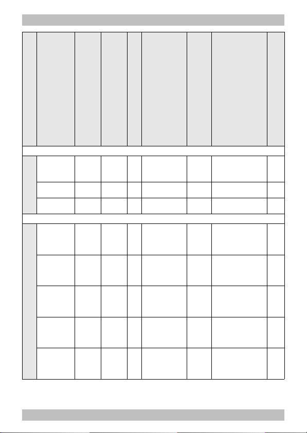
English Locomotive decoders of the series 30 plus
Max. total current [mA]
Max. current for motor [mA]
Number of outputs
Max. current / output [mA]
Max. current / output [mA]
Dimensions PCB [mm]
Weight [g]
LD-G-31 plus
without
wires
1 200 600 4 300 --- 19.5x9x4.5 1,0
NEM 652 1 200 600 4 300 --- 19.5x9x4.5 3,0
PluX12 1 200 600 4 300 --- 19.5x9x7.5 1,2
LD-G-33 plus
without
wires
1 500 1 000 9
F0f, F0r,
AUX1 – AUX6:
500
AUX7:
100
25.5x15.5x5 2,0
NEM 652 1 500 1 000 9
F0f, F0r,
AUX1 – AUX6:
500
AUX7:
100
25.5x15.5x5 5,0
PluX22 1 500 1 000 9
F0f, F0r,
AUX1 – AUX6:
500
AUX7:
100
25.5x15.5x7.5 2,5
21MTC 1 500 1 000 8
F0f, F0r,
AUX1, AUX2:
500
AUX3
-AUX6:
10
25.5x15.5x5 2,2
21-pole 1 500 1 000 8
F0f, F0r,
AUX1 - AUX4
500
AUX5,
AUX6:
10
25.5x15.5x5 2,2
Page 26
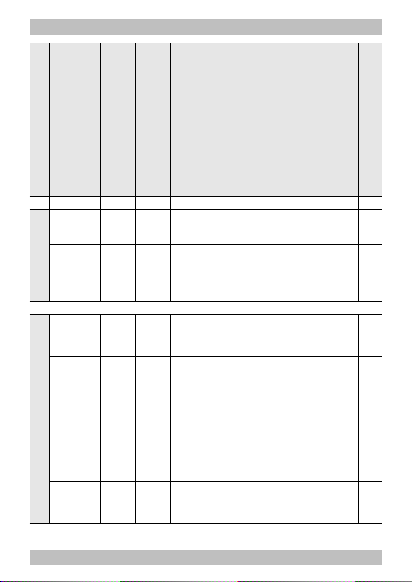
Locomotive decoders of the series 30 plus English
Max. total current [mA]
Max. current for motor [mA]
Number of outputs
Max. current / output [mA]
Max. current / output [mA]
Dimensions PCB [mm]
Weight [g]
LD-G-34 plus
without
wires
3 000 3 000 8 500 --- 27x17x6 3,0
with
wires
3 000 3 000 8 500 --- 27x17x6 5,0
NEM 652 3 000 1 500 8 500 --- 27x17x6 6,0
LD-G-36 plus
without
wires
1 500 1 000 9
F0f, F0r,
AUX1 - AUX6:
500
AUX7:
100
34.5x16x6 3,2
NEM 652 1 500 1 000 9
F0f, F0r,
AUX1 - AUX6:
500
AUX7:
100
34.5x16x6 5,2
PluX22 1 500 1 000 9
F0f, F0r,
AUX1 - AUX6:
500
AUX7:
100
34.5x16x6 3,5
21MTC 1 500 1 000 8
F0f, F0r,
AUX1, AUX2:
500
AUX3
-AUX6:
10
30x15.5x5 3,2
21-pole 1 500 1 000 8
F0f, F0r,
AUX1 - AUX4:
500
AUX5,
AUX6:
10
30x15.5x5 3,2
Page 27

!
English Locomotive decoders of the series 30 plus
6. Connections
Note the following comment in order to protect the
decoder from (maybe irreparable) damage!
Avoid all conducting connections between the decoder and
accessories connected to the decoder´s common return conductor for
all function outputs on the one hand and metal parts of the vehicle or
the rails on the other hand. Connections result for example from badly
isolated connecting wires (as well at the stripped ends of connecting
wires not in use) or insufficient fixing and isolating the decoder or the
accessory, for example. Risk of short circuit! In this case the overload
protection of the decoder is not able to protect the decoder from
damage.
Before connecting the motor, lighting or other accessories check if the
current is below the maximum permissible values and the total
current is below the safe load. Should the permissible current be
exceeded, this can result in damage to the decoder. Exceeding the
motor current or the permissible total current of decoders with
overload protection, will lead to switching off the decoder.
You should under no circumstances connect the decoder´s common
return conductor for all function outputs to vehicle ground. Risk of
short circuit!
Old analogue driving transformers (e.g. models in a blue housing from
Märklin**) are not suitable for use with digital decoders in analogue
operation! These transformers have been designed for the older
supply voltage of 220 V and, due to construction, generate very high
excess voltage impulses when changing the driving direction. When
using them with the modern supply voltage of 230 V too high excess
voltage impulses can occur, damaging electronic parts on the
decoder. For that reason only use driving transformers designed for a
net voltage of 230 V.
Page 28

Locomotive decoders of the series 30 plus English
6.1. Connector pin assignment LD-G-31 plus (PluX12)
Versions:
PluX12 (NEM 658), 8-pole plug (NEM652), without wires
LD-G-31 plus
- Front side -
LD-G-31 plus
- Back side -
Front
side
Colour
of wire
Connection to
(for use of settings in state of delivery)
X1 white F0f = lighting forward motion (function key F0)
X2 orange Motor connection 1 (plus)
X3 blue RL = common return conductor for all function
outputs (+)
X4 grey Motor connection 2 (minus)
X5 --- Index, not occupied
X6 red Right current collector (or slider)
X7 yellow F0r = lighting backward motion (function key F0)
X8 black Left current collector (or vehicle ground)
X9 brown Loudspeaker connection A (signal / -)
X10 green AUX1 (function key F1)
Page 29

English Locomotive decoders of the series 30 plus
Front
side
Colour
of wire
Connection to
(for use of settings in state of delivery)
X11 brown Loudspeaker connection B (+)
X12 violet AUX2 (function key F2)
X13 grey Switching input IN1
X14 grey Switching input IN2
Back
side
Colour
of wire
Connection to
X15 brown Negative pole (-) of buffer capacitor;
Earth connection for reed contacts / Hall sensors
X16 blue Positive pole (+) of buffer capacitor;
Supply voltage for Hall-Sensor
Page 30

Locomotive decoders of the series 30 plus English
6.2. Connector pin assignment LD-G-33 plus (PluX22)
Versions:
PluX22 (NEM 658), 8-pole plug (NEM652), without wires
LD-G-33 plus
with PluX22-interface
- front side -
LD-G-33 plus
mit PluX-Schnittstelle
- back side -
Front
side
Colour
of wire
Connection to
(for use of settings in state of delivery)
X1 orange Servo output
X2 white AUX3 (function key F5)
X3 grey SUSI CLOCK or switching input IN1
X4 grey SUSI DATA or switching input IN2
Page 31

English Locomotive decoders of the series 30 plus
Front
side
Colour
of wire
Connection to
(for use of settings in state of delivery)
X5 brown Earth connection for reed contacts / Hall sensors;
X6 blue Positive pole (-) of buffer capacitor;
Supply voltage for Hall sensors
X7 white F0f = lighting forward motion (function key F0)
X8 orange Motor connection 1 (plus)
X9 blue RL = common return conductor for all function
outputs (+)
X10 grey Motor connection 2 (minus)
X11 --- Index, not occupied
X12 red Right current collector (or slider)
X13 yellow F0r = lighting backward motion (function key F0)
X14 black Left current collector (or vehicle ground)
X15 brown Loudspeaker connection A (signal / -)
X16 green AUX1 (function key F1)
X17 brown Loudspeaker connection B (+)
X18 violet AUX2 (function key F2)
X19 white AUX4 (function key F6)
X20 white AUX5 (function key F10)
X21 white AUX6 (function key F11)
X22 white AUX7 (function key F13)
X23 orange Servo output (alternative to X1)
X24 brown Negative pole (-) of buffer capacitor;
Earth connection for servo
Page 32

Locomotive decoders of the series 30 plus English
6.3. Connector pin assignment LD-G-33 plus (21MTC, 21-pole)
Versions: 21MTC (NEM 660)
and 21-pole socket (similar to 21 MTC)
LD-G-33 plus
with MTC-interface or
21-pole interface
- front side -
LD-G-33 plus
with MTC-interface or
21-pole interface
- back side -
Front
side
Colour
of wire
Connection to
(for use of settings in state of delivery)
X1/X2 --- Not occupied
X3 *
3
white
AUX6 (function key F11) *
3
X4 *
3
white
AUX4 (function key F6) *
3
X5 grey SUSI CLOCK or switching input IN1
X6 grey SUSI DATA or switching input IN2
Page 33

English Locomotive decoders of the series 30 plus
Front
side
Colour
of wire
Connection to
(for use of settings in state of delivery)
X7 yellow F0r = lighting backward motion (function key F0)
X8
white
F0f = lighting forward motion (function key F0)
X9 brown Loudspeaker connection A (signal / -)
X10 brown Loudspeaker connection B (+)
X11 --- Index, not occupied
X12 --- Internal decoder voltage VCC: not intended for
external connection
X13 *
3
white
AUX3 (function key F5) *
3
X14 violet AUX2 (function key F2)
X15 green AUX1 (function key F1)
X16 blue RL = common return conductor for all function
outputs (+); Supply voltage for Hall sensors
X17 *
3
white
AUX5 (function key F10) *
3
X18 grey Motor connection 2 (minus)
X19 orange Motor connection 1 (plus)
X20 brown Earth connection for reed contacts / Hall sensors
X21 black Left current collector (or vehicle ground)
X22 red Right current collector (or slider)
Back
side
Colour
of wire
Connection to
(for use of settings in state of delivery)
X23 blue Positive pole (+) of buffer capacitor
X24 brown Negative pole (-) of buffer capacitor
X25 orange Servo output
X26 brown Earth connection for servo
*3 Max. current 21 MTC (NEM 660) 21-pole
AUX3 / AUX4 10 mA (not boosted) 500 mA (boosted)
AUX5 / AUX6 10 mA (not boosted) 10 mA (not boosted)
Page 34

Locomotive decoders of the series 30 plus English
6.4. Connector pin assignment LD-G-34 plus
Versions: without / with wires, 8-pole plug (NEM652)
LD-G-34 plus
- Front side -
LD-G-34 plus
- Back side -
Page 35

English Locomotive decoders of the series 30 plus
Front
side
Colour
of wire
Connection to
(for use of settings in state of delivery)
X1 white F0f = lighting forward motion (function key F0)
X2 yellow F0r = lighting backward motion (function key F0)
X3 green AUX1 (function key F1)
X4 violet AUX2 (function key F2)
X5 white AUX3 (function key F5)
X6 white AUX4 (function key F6)
X7 white AUX5 (function key F10)
X8 white AUX6 (function key F11)
X9 blue RL = common return conductor for all function
outputs (+)
X10 orange Servo output
X11 brown Earth connection for reed contacts / Hall sensors
X12 brown Negative pole (-) of buffer capacitor;
Earth connection for servo
X13 blue Positive pole (+) of buffer capacitor;
Supply voltage for Hall sensors
X14 brown Loudspeaker connection B (+)
X15 brown Loudspeaker connection A (signal / -)
X16 grey Switching input IN2
X17 grey Switching input IN1
Back
side
Colour
of wire
Connection to
(for use of settings in state of delivery)
X18 red Right current collector (or slider)
X19 black Left current collector (or vehicle ground)
X20 grey Motor connection 2 (minus)
X21 orange Motor connection 1 (plus)
Page 36

Locomotive decoders of the series 30 plus English
6.5. Connector pin assignment LD-G-36 plus (PluX22)
Versions:
PluX22 (NEM 658), 8-pole plug (NEM652), without wires
LD-G-36 plus with PluX22 interface – front side -
LD-G-36 plus with PluX22 interface – back side -
Colour
of wire
Connection to
(for use of settings in state of delivery)
X1 orange Servo output
X2
white
AUX3 (function key F9)
Page 37

English Locomotive decoders of the series 30 plus
Colour
of wire
Connection to
(for use of settings in state of delivery)
X3 grey SUSI CLOCK
X4 grey SUSI DATA
X5 brown Negative pole (-) of buffer capacitor;
Earth connection for reedcontacts / Hall-sensors
X6 blue Positive pole (+) of buffer capacitor
X7
white
F0f = lighting forward motion (function key F0)
X8 orange Motor connection 1 (plus)
X9 blue RL = common return conductor for all outputs (+)
X10 grey Motor connection 2 (minus)
X11 --- Index, not occupied
X12 red Right current collector (or slider)
X13 yellow F0r = lighting backward motion (function key F0)
X14 black Left current collector (or vehicle ground)
X15 brown Loudspeaker connection A (signal / -)
X16 green AUX1 (function key F5)
X17 brown Loudspeaker connection B (+)
X18 violet AUX2 (function key F6)
X19
white
AUX4 (function key F10)
X20
white
AUX5 (function key F11)
X21
white
AUX6 (function key F13)
X22
white
AUX7 (function key F14)
X23 brown Earth connection for sound clock generator
(reedcontact or Hall-sensor)
X24 blue Voltage supply for sound clock generator (Hall-Sensor)
X25 grey Input for sound clock generator
(reedcontact or output Hall-sensor)
Page 38

Locomotive decoders of the series 30 plus English
6.6. Connector pin assignment LD-G-36 plus (21MTC, 21-pole)
Versions: 21MTC (NEM 660)
and 21-pole socket (similar to 21 MTC)
LD-G-36plus
with MTC-interface
or 21-pole interface
- Front side -
LD-G-36plus
with MTC-interface
or 21-pole interface
- Back side -
Page 39

English Locomotive decoders of the series 30 plus
Front
side
Colour
of wire
Connection to
(for use of settings in state of delivery)
X1/X2 --- Not occupied
X3 *4white AUX6 (function key F11) *
4
X4 *4white AUX4 (function key F6) *
4
X5 grey SUSI CLOCK
X6 grey SUSI DATA
X7 yellow F0r = lighting backward motion (function key F0)
X8 white F0f = lighting forward motion (function key F0)
X9 brown Loudspeaker connection A (signal / -)
X10 brown Loudspeaker connection B (+)
X11 --- Index, not occupied
X12 --- Internal decoder voltage VCC: not intended for
external connection
X13 *4white AUX3 (function key F5) *
4
X14 violet AUX2 (function key F2)
X15 green AUX1 (function key F1)
X16 blue RL = common return conductor for all function
outputs (+)
X17 *4white AUX5 (function key F10) *
4
X18 grey Motor connection 2 (minus)
X19 orange Motor connection 1 (plus)
X20 brown Earth connection for reed contacts / Hall-sensors
X21 black Left current collector (or vehicle ground)
X22 red Right current collector (or slider)
Page 40

Locomotive decoders of the series 30 plus English
Front
side
Colour
of wire
Connection to
(for use of settings in state of delivery)
X23 red SUSI PLUS;
Positive pole (+) of buffer capacitor
X24 blue SUSI CLOCK or switching input IN1
X25 grey SUSI DATA or switching input IN2
X26 black SUSI GND;
Negative pole (-) of buffer capacitor
X27 Not intended for external connection
Back
side
Colour
of wire
Connection to
(for use of settings in state of delivery)
X28 grey Supply voltage for sound clock generator
(reedcontact or output Hall-sensor)
X29 brown Earth connection for sound clock generator / servo
(reedcontact, Hall-sensor, servo)
X30 blue Voltage supply for for sound clock generator
(Hall-Sensor)
X31 orange Servo output
*4 Max. current 21 MTC (NEM 660) 21-pole
AUX3 / AUX4 10 mA (not boosted) 500 mA (boosted)
AUX5 / AUX6 10 mA (not boosted) 10 mA (not boosted)
Page 41

English Locomotive decoders of the series 30 plus
6.7. Using decoders with interface connectors
Many recent locomotives with d.c. motor are equipped ex works with an
interface socket or an interface plug. Using a decoder with a suitable
connector saves separating the connections and soldering works at the
locomotive. Possible versions:
Description Number of poles MOROP standard
8 pole 8 NEM 652
PluX12,-16,-22
(Fig.: PluX12)
11, 15 oder 21 NEM 658
21MTC 21 NEM 660
(2 boosted outputs)
21 pole
(similar to
21MTC)
21-pole 21 ---
(4 boosted outputs)
The interface enables you to connect the decoder to the motor, the rail
current collectors, the lighting and – provided the special connector is
designed for it – additional accessories.
When mounting decoders with 6-pole interface connectors according to
NEM 651 or 8-pole interface connectors according to NEM 652, take
care to put the markings on the connector and on the socket on top of
each other. The PluX-connectors according to NEM 658 and 21MTC
-connectors according to NEM 660 can be mounted in one direction
only.
You can use a decoder with PluX12 interface connector in a locomotive
with PluX16 or PluX22 interface as well. All functions provided by the
decoder are available then.
Page 42

Locomotive decoders of the series 30 plus English
Hint:
There are locomotives available that have interfaces physically going
up to the 21MTC interface, but not having 2 boosted outputs
(corresponding to NEM 660) but 4 boosted outputs. Only locomotives
made corresponding to NEM 660 are allowed to be labelled with the
21MTC logo.
Please check on the package and in the manual of your locomotive
whether the interface corresponds to NEM 660 or not and use the
suitable decoder version.
6.8. Use in locomotives with a.c. motor
The locomotive decoders of the series 30 plus have been designed to
control direct current (d.c.) motors, for that reason they cannot be
connected directly to alternating current (a.c.) motors. You can control
a.c. motors with the locomotive decoders of the series 30 plus and
benefit of the load control when
mounting a load control adapter between a.c. motor and decoder or
replacing the field coil of the a.c. motor by a permanent magnet.
Page 43

English Locomotive decoders of the series 30 plus
6.9. INFO: Earth connections and voltage outputs
Most locomotive decoders of the series 30 plus have several earth
connections (-) as well as voltage outputs (+). In the connection lists
the connections for the return conductors of the accessories, for the
servos, reed contacts and Hall sensors and the buffer capacitors are
specified as they are most practicable for usual assignment. You can
choose another assignment of the earth connections (-) and the voltage
outputs if necessary.
Possible assignments to
earth connections (-)
Possible assignments to
voltage outputs(+)
Return
conductor of the
accessories
--- Common return
conductor for all function
outputs
Buffer capacitor negative pole positive pole
Reed contacts earth connection --Hall sensors earth connection supply voltage
Servo earth connection ---
Hint: You need an external
supply voltage for the servos!
Page 44

!
Locomotive decoders of the series 30 plus English
6.10. Mounting decoders without interface
Locate the position for the decoder after opening the locomotive
housing. Disconnect the motor from the rail current collectors or the
change-over switch from the motor and rails if you have a locomotive
with electronic change-over switch. The change-over switch is no
longer necessary, you can remove it.
Caution:
The interference suppression devices mounted to the motor or the
connecting wire must not be removed! Motor and interference
suppression devices are one unit. If even one part is removed, it can
cause extreme interference!
Connecting the decoder to the motor
Connect the decoder to the rail current collectors and to the motor.
Should the locomotive´s direction of motion in analogue mode not
match the direction of motion set at the speed control you have to
swap the connections to the rail current collectors / the slider.
Fig. 1: Connection of
the motor and the
power supply
Page 45

!
English Locomotive decoders of the series 30 plus
Connecting accessories to the outputs
Disconnect any existing diodes in the leads to the lamps, otherwise the
lamps might not light. Connect the lamps and the accessories to the
function outputs of the decoder. If the lamp or the accessory is already
connected with one side to vehicle ground, the connection is complete.
If not, connect the second side of the lamp or the accessory to the
decoder´s common return conductor for all function outputs.
You find the factory (default) settings in the lists with the connector pin
assignments. You can assign the outputs to the function keys
voluntarily by setting the configuration variables.
Fig. 2: Examples for the
connection of accessories
and LEDs to the function
outputs
F0f and F0r: Light forward /
backward motion
AUX1: parallel connection
of LEDs
AUX3: serial connection of
LEDs
AUX4: combined parallel
and serial connection of
LEDs
Attention: The examples of connection are suitable to only a
limited extent for the decoders with 21MTC and 21 pole interface. With the
decoders with 21MTC interface AUX3 to AUX6 and with the decoders with
21 pole interface AUX5 and AUX6 have a capacity of only 10 mA!
Page 46

!
Locomotive decoders of the series 30 plus English
6.11. Connecting LEDs to the function outputs
The decoder´s function outputs switch respective to the decoder
ground. For that reason you must connect the cathodes (-) of the LEDs
to the function outputs and the anodes (+) to the decoder´s common
return conductor for all function outputs.
Caution:
If you use light-emitting diodes (LEDs) you must always operate them via
a series resistor, otherwise they will be damaged when put into operation
or their duration of life will be reduced considerably!
When doing without a series resistor, other components undertake the
series resistor´s function (e.g. rails, wheels, current connectors), possibly
leading to a modification of the data signal and thus to disturbances in
digital operation.
Always determine the necessary series resistor´s value for the peak
value of the available operating voltage. With regulated boosters this
corresponds to the specified boosters´ output (= track) voltage. With
not regulated boosters or analogue driving transformers the peak
value is approx. 1,4 fold the nominal voltage specified on the
transformer.
Serial connection of LEDs
When you want to connect several LEDs to one output you can switch them
in series via a common series resistor. The current consumption is max. 20
mA for all LEDs, depending on the series resistor´s value. The maximum
number of LEDs to be connected in series results from
Peak value of the operating voltage
- sum of the forward voltages of all LEDs
> 0
The advantage of this solution is the low current consumption.
In order to determine the necessary series resistor for a serial LED´s
Page 47

English Locomotive decoders of the series 30 plus
connection first add the forward voltages of all LEDs. The forward
voltages depend on the lighting colour and should be given in the
technical specifications. In case there is no manufacturer information
available, you can take as a basis 4 V for white and blue LEDs and 2 V
for yellow, orange, red and green LEDs.
The remaining voltage has to be "eliminated" by a resistor. The formula
for the calculation of the resistor is:
required RV [Ohm] = ( UB [V] – ∑ UF [V] ) / (IF [mA] x 0.001)
UB = operating voltage (peak value) | ∑ UF = sum of the forward voltages of all LEDs
IF = current with max. luminosity
Parallel connection of LEDs
Alternatively, you can connect several LEDs in parallel, each via a series
resistor of its own. The current consumption is max. 20 mA for all LEDs,
depending on the series resistor´s value. The maximum number of LEDs to
be connected in parallel results from
maximum current at the output
- sum of the current consumption of all LEDs
> 0
Advantageous with this solution is that the LEDs already lighten when
their forward voltage has been reached (2 to 4 V, depending on the
fluorescent colour), which makes this solution suitable for analogue
mode. Disadvantageous is the high current consumption.
The formula for the calculation of the resistor is:
required RV [Ohm] = ( UB [V] – UF [V] / (IF [mA] x 0.001)
UB = operating voltage (peak value) | UF = forward voltage of the LED
IF = current with max. luminosity
In order to save current, you can limit the LEDs´current consumption to
10 mA, which normally does not cause a visible loss of luminance.
Page 48

Locomotive decoders of the series 30 plus English
6.12. Connecting inductive loads
When connecting inductive loads (e.g. TELEX couplings, relays or other
accessories with coils), you should switch a free-wheeling diode (e.g.
1N400x) in parallel, in order to avoid damage at the output. Check to
connect the anode of the diode to the function output.
6.13. Connecting accessories via a relay
When you want to switch an accessory / accessories via the decoder,
which connection would lead to exceeding the maximum current at the
output or of the decoder, you can switch the accessories via a relay
(e.g. 1xUm 1A 12V, item-no. 84-61010) and connect them directly to
the vehicle´s current collector.
The current consumed by the relay depends on its type. The relay named in
the example needs approx. 100 mA.
As described in the section "Connecting inductive loads" you should
switch a free-wheeling diode (e.g. 1N400x) in parallel to the relay.
Fig. 3: Connection of an accessory via a relay
Page 49

English Locomotive decoders of the series 30 plus
6.14. Connecting a loudspeaker
Use a loudspeaker with an impedance of at least 4 Ohm. When
connecting a loudspeaker with a lower impedance, the output for the
loudspeaker will be damaged. As a rule the playback quality increases
with the loudspeaker´s size. For that reason you should choose a
loudspeaker as large as possible.
In addition, the correct mounting of the loudspeaker is decisive for the
sound reproduction. The loudspeaker membrane should emit directly to
the outside, the other side into the inside of the vehicle which should
be as airtight as possible. The larger the volume in the inside, the
better is the reproduction quality. Suitable for the mounting are e.g. the
bottom of the vehicle or the back of the driver´s cab.
Clearing disturbances of the sound reproduction
As a matter of principle the sound playback can be distorted or
disturbed by a high whistling noise. In this case you should solder a
suppression choke (> 470 µH / 90 mA) into one of the supply wires of
the loudspeaker (except with the LD-G-36 plus).
Disturbing noises can occur with a bad current draw (e.g due to dirty
rails or at points) and with RailCom switched on. You can remedy these
disturbances by mounting a buffer capacitor.
6.15. Connecting a buffer capacitor
In sections with bad contact to the rails the power supply of the
decoder can be interrupted. Possible consequences are e.g. flickering
lighting or disturbing noises from the loudspeaker. In these and similar
cases you can find a remedy by connecting a buffer capacitor.
The electrolytic capacitor should have a capacity of minimum 100 µF
(LD-G-31 plus) or 220 µF and a proof voltage of minimum 25 V. When
used in analogue a.c. layouts, a voltage of minimum 35 V is required.
Observe the correct polarity when connecting the capacitor!
Page 50

Locomotive decoders of the series 30 plus English
Fig. 4: Connection of a
buffer capacitor to
improve the voltage
supply and of a
suppression choke at
the loudspeaker
6.16. Connecting a servo (not with LD-G-31)
Connect the signal input of the servo to servo output and the earth
connection of the servo to an earth connection of the decoder. The
voltage supply for the servo should not be taken from the decoder, as
the decoder cannot supply the current needed to control the servo. For
that reason you need an external voltage supply for the servo (e.g.
servo PCB item no. 70-05900).
Fig. 5: Connecting a
servo
Page 51

English Locomotive decoders of the series 30 plus
6.17. Connecting the switching inputs
Depending on the decoder type and layout you can connect
components to be used to trigger the switching inputs (e.g.
reedcontacts or Hall sensors) either directy to the soldering points or
via the SUSI interface. With the decoder versions equipped with a SUSI
plug (LD-G-33 plus and LD-G-36 plus in the PluX version), you need a
SUSI socket with wire for the connection of the switching inputs (e.g.
item no. 70-01111).
Versions Soldering
points
SUSI-interface
LD-G-31 plus all X13 | X14 ---
LD-G-33 plus *5without wires,
NEM652-plug
X3 | X4 via
SUSI-socket
LD-G-33 plus *5PluX22, 21 MTC,
21-pole
via
SUSI-socket
LD-G-34 plus all X16 | X17 ---
LD-G-36 plus *5PluX22, without
wires, NEM652plug
--- via
SUSI-socket
LD-G-36 plus *521 MTC,
21-pole
--- Soldering
points
X24, X25
*5 With the LD-G-33 plus you can either use the switching inputs or
connect a SUSI module. With the LD-G-36 plus you can simultaneously
use the switching inputs and connect a SUSI module, the SUSI module
has to be connected to the appropriate connections of the PluX
interface in this case.
The switching inputs switch respective to the decoder ground and thus
can be connected to all (external) circuits allowing to make contact to
Page 52

!
!
Locomotive decoders of the series 30 plus English
earth. It is possible to connect reed contacts or Hall sensors, for
example, which make contact to earth when getting into the magnetic
field of a permanent magnet.
You can switch the switching inputs respective to the decoder mass as
an alternative. In this case you have to solder a resistor (3,3 kOhm)
into the connection between switching input and earth of the rails.
Connect the reed contacts to the switching inputs and an earth
connection of the decoder. Reed contacts are not polarized, you can
assign the two contacts voluntarily.
When connecting Hall sensors check for the correct polarity. Connect
the earth connection of the Hall sensor to an earth connection of the
decoder, the connection for the voltage supply to a voltage output of
the decoder and the output to one of the switching inputs.
When exchanging the earth connection for the connection of the
voltage supply, the Hall sensor can be damaged!
Fig. 6: Connection or
reed contacts and Hall
sensors to the
switching inputs
Assigning the connections when using the SUSI interface:
SUSI PLUS Supply voltage for reed contacts or Hall sensors
SUSI CLOCK Switching input IN1
SUSI DATA Switching input IN2
SUSI GND Earth connection for reed contacts or Hall sensors
Page 53

English Locomotive decoders of the series 30 plus
6.18. Connecting a SUSI module (except LD-G-31 plus)
The SUSI interface is a standardized interface for the connection of
accessory modules to a vehicle decoder. Controlling the SUSI module has
to be carried out by the vehicle decoder. In order to make the necessary
settings for the SUSI module you have to program the decoder.
The decoder (except LD-G-36 plus with 21MTC- or 21-pole interface)
has a soldered SUSI-plug, fit to insert the socket of the SUSI module.
With the LD-G-36 plus with MTC- or 21-pole interface you can solder a
SUSI module on the soldering pads provided for that purpose.
There are connections according to SUSI integrated in the 21MTC-and
the PluX22 interface, as well. Only the decoder versions without PluXplug or MTC-socket are suitable for connecting an external SUSI
module to these connecting points.
Please note, that with the locomotive decoder LD-G-33 plus you can
either connect a SUSI module or use the switching inputs. With the
decoders LD-G-34 plus and LD-G-36 plus you can both connect a SUSI
module and use the switching inputs.
6.19. Connecting a clock generator to the LD-G-36 plus
You can control for example the correct synchronisation of the steam
discharge with the wheel movements. For that purpose connect a reed
contact or a Hall sensor as a clock generator and fix two or more mini
magnets to the wheels. When connecting a Hall sensor observe the right
polarity.
6.20. Fixing the decoder
After having finished all connections you should fix the decoder, to
avoid short circuits by contact to metal parts of the vehicle, for
example. You can use double sided adhesive tape for it, for example.
Page 54

Locomotive decoders of the series 30 plus English
7. Programming
Programming with DCC central units
You can program the configuration variables (CV) of the decoder from
the digital central unit, you can use main track programming as well.
See the chapter in the manual of your central unit where the byte wise
programming of configuration variables (CVs) (Direct programming)
and main track programming (POM) are explained. With central units
that allow only register-programming it is not possible to program the
decoder.
Programming with Motorola central units
In Motorola format the settings are saved in registers.
Please note: If you use a central unit for both DCC and Motorola format
it is recommended to program the decoder in the DCC format. After
having finished programming the decoder it is possible to control it in
Motorola format as well.
Please note: You should connect a lamp or a LED to at least F0f or F0r
before starting to program the decoder with a Motorola central unit, as
the decoder shows the status of the programming by flashing the
lighting connected to these outputs. The flashing frequency shows,
which input the decoder expects:
Slow flashing Fast flashing
Number of the register to be
programmed
Value of the register to be
programmed
Put the vehicle on a track oval or a track section connected to the
central unit’s track output (not to the connection for the programming
track). Make sure no other vehicle than the one you intend to program
is set on the track as the decoder inside this vehicle might be
programmed as well.
Page 55

English Locomotive decoders of the series 30 plus
Starting
the programming mode
Programming the decoder
1. Switch on the central unit or
perform a reset at the central
unit (pushing "stop" and "go"
simultaneously).
2. Set the current decoder
address (default value: 3) or
the address "80".
3 Set all functions to "off".
4. Push button "stop"
à switch off the track voltage.
5. Operate the direction switch
and hold it in that position.
Push the button "go" at once.
6. As soon as the lighting
flashes, release the
direction switch.
1. Enter the number of the
register as a Motorola-address.
If necessary: with a leading "0".
2. Operate the direction switch.
à Lighting flashes faster.
3 Enter the value you want to
set into the register
(as Motorola-address).
4. Operate the direction switch.
à Lighting flashes more slowly.
Repeat steps 1 – 4
for all registers.
Push button "stop".
à Programming mode à End of programming mode.
Programming with central units with restricted input options
Some central units do not allow but input values up to 80 or 99. Two
auxiliary registers (CV#26 and #30) make it possible to enter higher values.
Programming with the Central Station and the Mobile Station
With the Central Station I or the Mobile Station of Märklin** you can
program the registers. Select the article no. 29750 from the locomotive
database and program the decoder as described for this article in the
Central Station´s or Mobile Station´s manual.
Page 56

Locomotive decoders of the series 30 plus English
Programming with the CV-Navi
Instead of programming the configuration variables or registers of the
decoder using the digital central unit, you can use the free software CVNavi. In order to use the software, you need a digital central unit supporting
the p50x-protocol (e.g. Tams MasterControl or Intellibox of Uhlenbrock**).
You will find the free download presumably from beginning of 2014 under:
www.tams-online.de
Page 57

English Locomotive decoders of the series 30 plus
8. Configuration variables and registers
In the lists you will find in the column "No." the numbers of the
configuration variables for programming in DCC format. The numbers of
the registers for programming in Motorola format are identical to the CV
numbers. The defaults are those values set in the state of delivery and
after a reset.
Please note: With variables destined to set several parameters, the
input value has to be calculated by adding the numerical values
assigned to the desired parameters.
Setting the address
Name of CVs /
registers
No. Input value
(Default)
Remarks and Tips
Basic address 1 1 ... 255
(3)
Range of values in
DCC-Format: 1 ... 127
Tip: If a value higher than 127 is set for the basic address and the use of extended addresses
in CV#29 is set to off, the decoder does not react to signals in DCC format!
Extended
address
17 192 ... 255
(192)
Only for DCC format. Most
central units permit entering
extended addresses directly.
The CVs # 17, 18 and 29 are
set automatically to the proper
values.
18 0 ... 255
(255)
Consist
address
19 1 ... 127 (0) = 2nd adress
In DCC format only!
2nd Motorola
address
47 0 … 255 (4)
= Address needed to switch
additional functions in Motorola
format. The function keys F5 to
F8 are reached via the function
keys F1 to F4, the function key
F9 via the function key F0.
Page 58

Locomotive decoders of the series 30 plus English
Information / Read only
Name of CVs /
registers
No. Input value
(Default)
Remarks and Tips
Version 7 ---
Read only in DCC format!
Manufacturer 8 --- (62)
Read only in DCC format!
Index for
higher CV
pages
31 --- (0) Set firmly.
For reading out RailCom
relevant data. Only for DCC
format.
32 --- (255)
Auxiliary functions
Name of CVs /
registers
No. Input value
(Default)
Remarks and Tips
Reset 8 0 ... 255 Any input value restores the
settings in state of delivery.
Auxiliary
register for
programming
with central
units with
restricted
input options
2630(0)
(0)
Allows to enter values > 80
resp. 99 with central units
allowing to entries from 0 or 1
to 80 or 99.
Number of CV
Value of CV
In CV #26 and 30 you preset the hundred and the tenner for the CV number
and CV value. In order to program a CV number > 80 or 99 you have to
program the desired "one" value into the CV with the corresponding "one"
number. Instead of a "0" you can enter "10" (with those central units not
allowing to enter a "0"). Examples:
CV#137 value 245→
1. CV#26 =13 (1= the 100 | 3 =10ner)
2. CV#30= 24 (2= the 100 | 4 = 10ner)
3 CV#7 = 5 (7 = the one of the CV
number, 5 = the one of the CV value)
CV#120 value 230→
1. CV#26 =12 (1= the 100 | 2 =10ner)
2. CV#30= 23 (2= the 100 | 3 = 10ner)
3 CV#10 = 0 or 10 (10 for value 0 of the one of
the CV number, 0 or 10 for value 0 of the one of
the CV value)
Page 59

English Locomotive decoders of the series 30 plus
Settings for analogue mode
Name of CVs /
registers
No. Input value
(Default)
Remarks and Tips
Packet
time out for
analogue
recognition
11 0 ... 255 (5) The higher the set value, the
longer it takes until the decoder
automatically switches to
analogue mode after having
received the last digital signal .
Analogue
mode
12 0, 1 (1) = Procedure triggering a change
of direction
Overvoltage impulse
(a.c. layouts) 0
Change of polarity
(d.c. layouts) 1
Functions
active in
analogue
mode
(only for F1 to
F8, not for F9
to F12)
13 0 ... 255 (0) F1 on 1
F2 on 2
F3 on 4
F4 on 8
F5 on 16
F6 on 32
F7 on 64
F8 on 128
Intensity of
overvoltage
impulse (for
analogue a.c.
layouts)
199 0 ... 255 (100) 0 = minimum voltage
255 = maximum voltage
Page 60

Locomotive decoders of the series 30 plus English
Basic settings
Name of CVs /
registers
No. Input value
(Default)
Remarks and Tips
RailCom
settings
28 0,1,2,3,128,
129,130,131
(131)
no feedback 0
channel 1 on 1
channel 2 on 2
RailComPlus on 128
Configuration
data 1
29 0 ... 64 (14) Direction "Standard" 0
Reverse direction 1
14 speed levels 0
28 or 128 speed levels 2
Analoge recognition off 0
Analoge recognition on 4
RailCom off 0
RailCom on 8
Linear velocity characteristic 0
Alternat. velocity charact. 16
Basic addresses 0
Not for MM mode: Extended addresses 32
Example: CV#29 = 0. à Direction = "Standard". 14 speed levels. Basic addresses. Automatic
analogue recognition = "off". RailCom = "off".
Example: CV#29 = 46. à Direction = "Standard". 28 or 128 speed levels in DCC-mode. Automatic
analogue recognition = "on". RailCom = "on". Extended addresses.
Tip: If the use of extended addresses is activated in CV#29, the decoder does not react to
signals in Motorola format!
Configuration
data 2
49 0 ... 255
(73)
Load control inactive 0
Lastregelung active 1
Shunting gear at F1 2
Shunting gear at F2 4
Shunting gear at F3 8
Shunting gear at F4 16
Acceleration and brake delay
to be switched at F3 32
Acceleration and brake delay
to be switched at F4 64
Page 61

English Locomotive decoders of the series 30 plus
Basic settings (continuation)
Name of CVs /
registers
No. Input value
(Default)
Remarks and Tips
Switching off
at overload
(not valid for
LD-G-31 plus and
LD-G-34 plus)
48 --- (45) Determines, at which current
the overload protection
responds. The higher the input
value, the higher is the current
responding at overload
protection.
45 = 1 500 mA
The value of 45 should be
altered as an exception only!
Setting the driving of the motor
Name of CVs /
registers
No. Input value
(Default)
Remarks and Tips
Starting
voltage
(Starting
velocity)
2 0 … 255
(6)
= The voltage to be output to
the motor at speed level 1.
0 = 0 Volt
255 = max. voltage
Acceleration
rate
3 0 … 255
(10)
= Length of the delay before
the switching to the next
higher / lower speed level when
the locomotive is accelerating /
braking.The delay is calculated
as follows:
(value of CV#3) x 0,9 sec. /
number of speed levels
Braking rate 4 0 … 255
(5)
Maximum
voltage
(maximum
velocity)
5 0 … 255
(255)
= The voltage to be output to
the motor at the highest speed
level.
2 = 0,8 % of the max. voltage
255 = maximum voltage
Page 62

Locomotive decoders of the series 30 plus English
Setting the driving of the motor (continuation)
Name of CVs /
registers
No. Input value
(Default)
Remarks and Tips
Medium
voltage
(Medium
velocity)
6 0 … 255
(100)
=The voltage to be output to
the motor at the medium speed
level.
2 = 0,8 % of the max. voltage
255 = maximum voltage
Motor
frequency
9 0 … 255
(0)
=Frequency controlling the
motor:
0 = 30 kHz
255 = 58 Hz
For values > 0: frequency [Hz]
= 30.000 / (2 x value of CV#9)
Braking
performance
with d.c.
voltage
27 0, 32, 64,96
(0)
No braking with d.c. voltage 0
Braking with
negative d.c. voltage 32
Braking with
positive d.c. voltage 64
Tip: It is standard to switch over into analogue mode when applying a d.c. voltage at the
rails. In case that the decoder is run in a layout with a braking route based on applying a d.c.
voltage (e.g. Märklin**-braking route), the analogue recognition has to be disactivated (in
CV#29) to ensure that the locomotive reacts as expected on the braking route.
The setting of the negative or positive d.c. voltage is related to the right rail, as seen in the
locomotive´s direction of motion.
Starting-kick 65 0 … 255 (0) = short-time increase of motor
voltage while starting to clear
the breakaway torque.
Example: CV#65 = 6 à The motor voltage while starting is equivalent to the voltage applied
in operation at speed level 6 (of 255). It is reduced immediately to the actually set speed level
with the braking rate defined in CV#4. Thus, when altering the value for CV#4 it may be
necessary to alter CV#65, too.
Page 63

English Locomotive decoders of the series 30 plus
Setting the driving of the motor (continuation)
Name of CVs /
registers
No. Input value
(Default)
Remarks and Tips
Alternative
velocity
characteristic
(only with
mode 28
speed levels)
68
.
.
95
0 ... 255 = velocity table for the
alternative velocity
characteristic. Any motor
voltage can be assigned to all of
the 28 speed levels.
0 = voltage of "0"
255 = maximum voltage
Setting the load control
Name of CVs /
registers
No. Input value
(Default)
Remarks and Tips
Parameter of
load control KP
50 0 ... 255 (16) = Proportional component of
the load control.
The parameter KP defines the basic speed.
A too small value à locomotive too slow.
A too high value à heavy shuttering of the locomotive.
Parameter of
load control KI
51 0 ... 255 (14) = Integral component of the
load control.
The parameter KI provides the fine tuning of the load control.
The value has to be adjusted in very small steps.
A too high value à heavy shuttering of the locomotive.
Parameter of
load control KD
52 0 ... 255 (8) = Differential component of the
load control.
The parameter KD retards the transforming of the load control.
A too small value à shaking of the locomotive.
A too high value à rocking of the locomotive.
Motor
adaptation 1
165 0 ... 20 (4) = Factor multiplying the value of
the load control
Motoradaptation 2
166 0 ... 20 (1) = Number of averagings of the
measured values of the load
control
Page 64

Locomotive decoders of the series 30 plus English
Optimising the CV-settings
Above all, the driving characteristics can be influenced by setting the
CV#2 (starting voltage), the CV#6 (medium velocity) and CV#5
(maximum voltage).
In addition, you can alter the parameters of the load control. To adjust
the parameters for the load control (CV#50 to #52) the following
procedure is recommended:
If the locomotive is shuttering: à Increase the value for CV#52 (KD) in
5-steps. If this does not lead to an improvement of the driving
characteristics, set the value of CV#52 back to factory setting (default
value). Then decrease the value for CV#50 (KP) in 5-steps and for
CV#51 (KI) in 2-steps.
If the locomotive does not have enough power and e.g. gets very slow
on the way uphill: à Increase the value for CV#51 (KI) in 2-steps,
until the locomotive starts to shutter. Then increase the value for
CV#52 (KD) in 5-steps. If this does not lead to an improvement or the
locomotive starts to shutter immediately after increasing CV#51, set the
values for CV#51 and CV#52 back to factory setting (default value) and
increase the value for CV#50 (KP) in 5-steps.
If the locomotive is rocking: à Decrease the value for CV#52 in 5steps.
If you are not content with the driving characteristics in slow approach,
you can influence them by altering CV#166 and CV#165. Start with
altering the value of CV#166 in 1-steps.
Tip: Setting the parameters of the load control is very difficult, a
change can result in a considerable worsening of the driving
characteristics. For that reason you should always alter the values in
small steps only. When altering the parameters of the load control does
not result in an improvement, you should reset the default values.
Page 65

English Locomotive decoders of the series 30 plus
Assignment of the outputs to the function keys F0 to F12
Please note: The LD-G-31 plus provides only the outputs F0f, F0r, AUX1
and AUX2.
Name of CVs /
registers
No. Input value
(Default)
Remarks and Tips
F0 forward on 33 0 ... 255 (1) F0f 1
F0r 2
AUX1 4
AUX2 8
AUX3 16
AUX4 32
AUX5 64
AUX6 128
F0 backward on 34 0 ... 255 (2)
F1 35 0 ... 255 (4)
LD-G-36: (0)
F2 36 0 ... 255 (8)
LD-G-36: (0)
F3 37 0 ... 255 (0)
F4 38 0 ... 255 (0)
F5 39 0 ... 255 (16)
LD-G-36: (4)
F6 40 0 ... 255 (32)
LD-G-36: (8)
F7 41 0 ... 255 (0)
F8 42 0 ... 255 (0)
F9 43 0 ... 255 (0)
LD-G-36: (16)
F10 44 0 ... 255 (64)
LD-G-36: (32)
F11 45 0 ... 255 (128)
LD-G-36: (0)
F12 46 0 ... 255 (0)
LD-G-36: (64)
Page 66

Locomotive decoders of the series 30 plus English
Assignment of the outputs to the function keys F13 bis F28
Name of CVs /
registers
No. Input value
(Default)
Remarks and Tips
F13 180
LD-G-31: (0)
LD-G-33 PluX: (64)
LD-G-33 MTC: (0)
LD-G-34: (0)
LD-G-36 PluX: (32)
LD-G-36 MTC: 0
AUX1 1
AUX2 2
AUX3 4
AUX4 8
AUX5 16
AUX6 32
AUX7 64
(not LD-G-33 plus MTC, LD-G-34 plus
and LD-G-36 plus MTC))
F14 181 0 ... 127 (0)
LD-G-36: (64)
... ... 0 ... 127 (0)
F28 195 0 ... 127 (0)
Eingabewerte für
Decoder ohne
AUX7:
0 … 63
Assignment of the outputs to the function keys /
Default values:
LD-G-31 plus, LD-G-33 plus
and LD-G-34 plus:
LD-G-36 plus:
F0f F0, switched on at forward motion
F0r F0, switched on at backward motion
AUX1 to be switched with F1 to be switched with F5
AUX2 to be switched with F2 to be switched with F6
AUX3 to be switched with F5 to be switched with F9
AUX4 to be switched with F6 to be switched with F10
AUX5 to be switched with F10 to be switched with F12
AUX6 to be switched with F11 to be switched with F13
AUX7 to be switched with F13 to be switched with F14
Example: F0r to be switched with F5 à CV#39 = 2
Example: F0f and AUX1 3 to be switched with F6 à CV#40 = 5 (= 1+4)
Page 67

English Locomotive decoders of the series 30 plus
Effects of the outputs
Name of CVs /
registers
No. Input value
(Default)
Remarks and Tips
F0f 53 0 ... 255 (0) Independent of direction 0
F0r 54 AUX off at backward motion 1
AUX1 55 AUX off at forward motion 2
AUX2 56 Function inverted 4
AUX3 57 Flashing inverted 8
AUX4 58 Flashing on 16
AUX5 59 MARslight on 32
AUX6 60 Double flashing on 64
Kick function on
(not for F0f and F0r) 128
Factory settings: The functions F1 to F28 switch the assigned outputs independant of the
direction of motion. F0 always switches dependant of the direction of motion.
Examples:
MARslight with F0f, switched on at forward motion: à Input value for CV#53 = 33 (= 1 + 32)
Alternating flashing with AUX2 and AUX3:
à Input value for AUX2: CV#56 = 16 | Input value for AUX3: CV#57 = 24 (16 + 8)
Settings for the flash lights
Name of CVs /
registers
No. Input value
(Default)
Remarks and Tips
Flashing frequency of the lighting
F0f 104 10 ... 255 (20) The flashing frequency
determines the duration of one
period.
10 = highest possible frequency
255 = lowest possible frequency
F0r 105
AUX1 106
AUX2 107
... ...
AUX6 111
Flashing
frequency of
the MARslight
for all outputs
112 0 … 255 (64) 0 = fast
255 = slow
Page 68

Locomotive decoders of the series 30 plus English
Settings for the flash lights (continuation)
Name of CVs /
registers
No. Input value
(Default)
Remarks and Tips
On-time of the flashlights
F0f 132 0 … 255 (4) The maximum value of the on-
time is the value set in CV#106
et seq.
The higher the input value, the
longer is the on-time.
F0r 133
AUX1 134
... ...
AUX6 139
Example: For AUX1 is set in
CV#106 a value of 100 for the
flashing frequency and in
CV#132 a value of 60 for the
on-time.
With a value of 50 in CV#134 on- and off-time would have the same length, with a value of
100 the light would be switched on permanently.
Double flashing: Length of the break beween the two flashlights.
F0f
140
0 … 255 (2) Frequency and on-time have to
be set in CV#104 et seq. and
CV#132 et seq. The length of
the break is the longer the
higher the input value is.
For the input values for CV#104
et seq., 132 et seq. and 140 et
seq. applies:
(CV#132) x 2 + (CV#140)
< (CV#104)
F0r
141
AUX1
142
AUX2
143
... ...
AUX6
147
Example: For AUX1 is set in
CV#106 a value of 100 for the
flashing frequency and in
CV#132 a value of 15 for the
on-time. The value for the
length of the break in CV#142
is 10.
In case 2 times the value of the on-time + the value of the length of the break would be higher than
the frequency, the sequence would be interrupted when reaching the end of the period.
Page 69

English Locomotive decoders of the series 30 plus
Dimming of the outputs
Name of CVs /
registers
No. Input value
(Default)
Remarks and Tips
F0f 115
1...255 (255) = Reduction of the voltage
applied to the output.
"1" = lowest voltage,
"255" = maximum voltage
F0r 116
AUX1 117
... ...
AUX6 122
Dimming of the outputs depending on the speed level
Name of CVs /
registers
No. Input value
(Default)
Remarks and Tips
Internal
speed level for
CV#114
113 1 ... 255 (10) = speed level, from which the
outputs defined in CV#114 are
dimmed with the settings in
CV##123 to 126 (instead of
settings in CV##115 to 118).
Outputs
dimmed
depending on
the speed level
114 0 … 15 (0) F0f 1
F0r 2
AUX1 4
AUX2 8
AUX3 16
AUX4 32
AUX5 64
AUX6 128
Dimming depending
on the speed level
= reduction of the voltage at
the output
"1" = lowest voltage
"255" = maximum voltage
Values are applied to the outputs
determined in CV#114 and starting from a
speed level determined in CV#113 only.
F0f
123 1...255 (255)
F0r
124
AUX1
125
...
...
AUX6
130
Page 70

Locomotive decoders of the series 30 plus English
Shunting light
Name of CVs /
registers
No. Input value
(Default)
Remarks and Tips
Shunting light 131 0 ... 255 (0) for F0f 1
for F0r 2
for AUX1 4
for AUX2 8
for AUX3 16
for AUX4 32
to be switched with F3 64
to be switched with F4 128
Example: For F0r and AUX1 shunting light, to be switched with F4:
à input value: 134 (= 2 + 4 + 128)
Kick function
Name of CVs /
registers
No. Input value
(Default)
Remarks and Tips
Extended
kickfunction
160 0 ... 252 (0) for AUX1 4
for AUX2 8
for AUX3 16
for AUX4 32
for AUX5 64
for AUX6 128
When setting the extended kick function for an output, the motor is supplied with power as
long as the kick function is switched on.
Example of use: When switching an output via the extended kick function the locomotive runs
automatically a little bit nearer to the carriage (in order to ease the burden from the
coupling). Afterwards the electric coupling is released via the kick function and the locomotive
moves away automatically from the uncoupled carriage.
Voltage at
extended kick
function
161 0 ... 255 (10) = Voltage applied to the motor
when switching an output via
the extended kick function.
Kicking time
for direction
"forwards" /
"backwards"
162
163
0 ... 255 (32) 0 = short
255 = long
Page 71

English Locomotive decoders of the series 30 plus
Assignment to the switching inputs
Name of CVs /
registers
No. Input value
(Default)
Remarks and Tips
Assigning the function outputs to the switching inputs
IN1 61 0 … 255 (0) F0f 1
IN2 63 0 … 255 (0) F0r 2
Hint: The switching inputs are released
respective to decoder ground. If you want to
release them respective to rail ground, you have
to mount a resistor (3,3 kOhm).
Hint: If you want to trigger sound functions or
the servo via the switching inputs, you have to
assign them to a function key (CV#62 and #64).
AUX1 4
AUX2 8
AUX3 16
AUX4 32
AUX5 64
AUX6 128
Assigning the functions to the switching inputs
IN1 62 0...255 (0) F1 1
IN2 64 0...255 (0) F2 2
The functions are released both via the function
keys and the assigned switching input.
Hint: The switching inputs are released
respective to decoder ground. If you want to
release them respective to rail ground, you have
to mount a resistor (3,3 kOhm).
F3 4
F4 8
F5 16
F6 32
F7 64
F8 128
Setting the minimum on-time of the switching inputs
Name of CVs /
registers
No. Input value
(Default)
Remarks and Tips
IN1 177 0 … 255 (1) = Length of time for the input
to be switched on after having
been connected to earth.
Increasing the value by "1" will
prolong the lenght of time by
1,1 sec.
0 = 0 sec. (off)
255 = 280.5 sec. (> 4 min.)
IN2 178 0 … 255 (1)
Page 72

Locomotive decoders of the series 30 plus English
Settings for integrated sounds (without LD-G-36 plus)
Name of CVs /
registers
No. Input value
(Default)
Remarks and Tips
Assignment of the function keys to the integrated sounds
F1 148 16,32,64 (0) Whistle 16
F2 149 16,32,64 (0) Signal horn 32
F3 150 16,32,64 (0) Bell 64
F4 151 16,32,64 (0)
F5 152 16,32,64 (0)
F6 153 16,32,64 (0)
F7 154 16,32,64 (16)
F8 155 16,32,64 (32)
F9 156 16,32,64 (64)
F10 157 16,32,64 (0)
F11 158 16,32,64 (0)
F12 159 16,32,64 (0)
You should assign only one sound to each function key.
Settings for the servo output (except LD-G-31 plus)
Name of CVs /
registers
No. Input value
(Default)
Remarks and Tips
Inverting the
functions F5
to F12 for the
servo output
(in
combination
with CV#167)
164 0 ... 255 (1) Exchanges left and right stopopf
the servo
Activation with F5 1
F6 2
F7 4
F8 8
F9 16
F10 32
F11 64
F12 128
Page 73

English Locomotive decoders of the series 30 plus
Settings for the servo output (Fortsetzung)
Name of CVs /
registers
No. Input value
(Default)
Remarks and Tips
Assignment
servo output
to the function
keys
167 0 ... 255 (2) Allowing the servo to be
controlled via POM 0
Activation with F5 1
F6 2
F7 4
F8 8
F9 16
F10 32
F11 64
F12 128
Determining
the operating
mode of the
servo output
168 0,1 (0) Allowing the servo to be
controlled via f-keys 0
Entering the servo folding
square via POM 1
Setting the servo The value for the right stop has
to be higher than the value for
the left stop.
left stop
169 40…250 (112)
right stop
170 40…250 (176)
velocity
171 0 … 255 (16) 0 = lowest velocity
255 = highest velocity
Controlling
the servo via
POM / servo
position
172 40…250
(restricted by:
CV#169 à lowest
value and CV#170
à hightest value)
The last via POM set value will
be saved and the corresponding
position will be headed for
automatically.
Note: Controlling the servo via POM is not
possible until CV#167 = 0 and CV#168 =
1.
Page 74

Locomotive decoders of the series 30 plus English
Coupling function
Name of CVs /
registers
No. Input value
(Default)
Remarks and Tips
Time-out for
coupling
function
96 0 ... 255 (10) = maximum length of time for
the coupling operation (in
seconds) before breaking off.
Function key
F1 to F4
and direction
for input 1
for input 2
97
99
0 ... 255 (0) = defines the function key
releasing the coupling function
and the direction of coupling
backwards 0
forwards 128
F1 1
F2 2
F3 4
F4 8
Function key
F5 to F12
and direction
for input 1
for input 2
Hint: Setting the
direction of travel
in CV##97 and 99
98
100
0 ... 255 (0) F5 1
F6 2
F7 4
F8 8
F9 16
F10 32
F11 64
F12 128
Hint: The switching inputs are released respective to decoder ground. If you want to release
them respective to rail ground, you have to mount a resistor (3,3 kOhm).
Motor voltage
for coupling
function
101 1 ... 255 (16) 0 = minimum voltage
(velocity = 0)
255 = maximum voltage
(maximum velocity)
Page 75

English Locomotive decoders of the series 30 plus
Commuting automatic
Name of CVs /
registers
No. Input value
(Default)
Remarks and Tips
Commuting
automatic
for input 1
for input 2
Hint:
It makes sense to
assign the terminal
stations to input 1
and the additional
stops to input 2.
(see CV#179)
196
197
0 ... 255 (0) Stop time = 0 Sek. 0
Stop time = 5 Sek. 1
Stop time = 10 Sek. 2
Stop time = 20 Sek. 4
Stop time = 40 Sek. 8
Extending the stop time (x4) 16
For both directions 32
For outward journey only 0
For return journey only 64
With change of direction 0
Without change of direction 128
Example: Commuting automatic between two terminal stations with 100 seconds stopping
time; releasing via switching input 1: à input value for CV#196: 53 (= 1 + 4 + 16 + 32 + 0)
Example: Additional stops with 30 seconds stopping time, for return journey only; releasing
via switching input 2: à input value for CV#197: 198 (= 2 + 4 + 64 + 128)
Switching off
the
commuting
automatic
with function
key F5 to F12
198 0 ... 255 (0) F5 1
F6 2
F7 4
F8 8
F9 16
F10 32
F11 64
F12 128
Switching
impulses for
input 1 to be
ignored
179 0 ... 255 (1) Prevents, that switching
impulses released between the
terminal stations release the
braking for the terminal station.
Hint: Except with very short commuting lines the stops at the two terminal stations are
released via separate contacts. In order to prevent the locomotive from stopping immediately
after driving back into the opposite direction, you have to program the value "1" in CV#179.
Example: In the example presented under CV##196 and 197 the locomotive is to stop at
both terminal stations and alter the direction and stop 3 times during return journey. The
stops at the terminal stations are released by separate contacts. Input value for CV#179: 4
Page 76

Locomotive decoders of the series 30 plus English
Special functions for speed level 0
Name of CVs /
registers
No. Input value
(Default)
Remarks and Tips
Switching off
function F0 at
speed level 0
173 0...255 (0) Determines the functions
(F1 to F8) to switch off the
function F0 at speed level 0.
F1 1
F2 2
F3 4
F4 8
F5 16
F6 32
F7 64
F8 128
Switching on
the outputs at
speed level 0
Switching off
the outputs at
speed level 0
Inverting the
outputs at
speed level 0.
off = on
on = off
174
175
176
... 255 (0)
0 ... 255 (0)
0 ... 255 (0)
Determines the outputs to be
switched on /off / inverted via
the functions defined in CV#173
at speed level 0.
F0f 1
F0r 2
AUX1 4
AUX2 8
AUX3 16
AUX4 32
AUX5 64
AUX6 128
Page 77

English Locomotive decoders of the series 30 plus
Sound-Update (LD-G-36 plus only)
Name of CVs /
registers
No. Input value
(Default)
Remarks and Tips
Sound-Update 103 0, 1 (0) Update impossible 0
Update possible 1
Hint: When entering the value "1" for CV#103, no sound will be played back! For that reason
you have to set the value for CV#103 back to "0" after a sound-update.
Setting the sound level (LD-G-36 plus only)
Name of CVs /
registers
No. Input value
(Default)
Remarks and Tips
Sound level 902 0 ... 255 (128) 0 = off
255 = maximum sound level
Assigning the function keys to the sounds (LD-G-36 plus only)
Name of CVs /
registers
No. Input value
(Default)
Remarks and Tips
F0 903 0 ... 8 (0) No sound 0
F1 904 0 ... 8 (3) Bell or horn 2 1
F2 905 0 ... 8 (2) Whistle or horn 1 2
F3 906 0 ... 8 (0) Standing or driving sound 3
F4 907 0 ... 8 (0) Decoupling or
door closing sound 4
F5 908 0 ... 8 (0)
F6 909 0 ... 8 (0) Fader for all sounds 8
F7 910 0 ... 8 (1)
F8 911 0 ... 8 (8)
F9 912 0 ... 8 (0)
F10 913 0 ... 8 (0)
F11 914 0 ... 8 (4)
F12 915 0 ... 8 (0)
Factory settings:
Function key F1 switches sound no. 3 (= standing or driving sound)
Function key F2 switches sound no. 2 (= signal horn1 or locomotive whistle)
Function key F11 switches sound no. 4 (= decoupling or door closing sound)
Function key F7 switches sound no. 1 (= signal horn 2 or bell)
Function key F8 switches fader (= fading in and down) for all sounds
Page 78

Locomotive decoders of the series 30 plus English
Basic settings for driving sound (LD-G-36 plus only)
Name of CVs /
registers
No. Input value
(Default)
Remarks and Tips
Configuration
variables
920 0 … 195 (129) Exhaust bangs via reed contact
only 0
Exhaust bangs automatically
and via reed contact 1
Break before repeating the
whistle 2
Cutting by half the
exhaust bangs 4
Fading time = 8 seconds
and automatic fading when
switching on 64
Power amplifier always
switched on
*
6
0
Power amplifier off, when sound
off
*
6
128
Factory settings:
Exhaust bangs automatically and via reed contact: on
Break before repeating the whistle: off
Cutting by half the exhaust bangs: off
Fading time = 8 seconds and automatic fading when switching on: off
Power amplifier off, when sound off
* For the configuration variables, the input values have to be calculated by adding the
numerical values assigned to the desired parameters.
*
6
In combination with some types of locomotive types disturbing noises can occur during
operation. The decoder can be set to switching the sound power amplifier off when no sounds
are released.
Page 79

English Locomotive decoders of the series 30 plus
Further settings for driving sound (LD-G-36 plus only)
Name of CVs /
registers
No. Input value
(Default)
Remarks and Tips
Release
threshold at
increase of
motor load
921 0 ... 128
(3)
0 = change of sound at least
increase or decrease of motor
load
128 = no change of sound at
increase or decrease of motor
load
Release
threshold at
decrease of
motor load
922 0 ... 128
(3)
Switching
threshold for
ventilator of
e-locomotives
923 0 ... 255
(128)
0 = immediate reaction towards
changes
128 = ventilator sound /
braking sound switched off
Threshold for
braking sound
924 0 ... 255
(44)
Reaction
to load
changes
925 1 ... 8
(6)
1 = quickest possible reaction
8 = slowest possible reaction
Time of noload running
937 1 ... 254
(15)
"0" = immediate return in the
load mode
"255" = no automatic return in
the load mode
Adjusting the exhaust bangs to the
locomotive´s speed level
For operation without clock
generator only!
Maximum of
exhaust bangs
938 50 ... 255
(0)
Minimum of
exhaust bangs
939 50 ... 255
(0)
Page 80

Locomotive decoders of the series 30 plus English
9. Performing a POM-Update
Hint: The POM-Update is possible with decoders from version 2.4
(LD-G-31 plus) or version 2.5 (LD-G-33 plus and LD-G-34 plus). For
updating decoders with a former firmware version you have to send
them in. The version number is saved in CV #7.
Preparations
1. In order to perform the firmware update you do not have to
dismount the decoder. Put the vehicle with the mounted decoder
on the main track. Hint: You can perform a firmware update with
several locomotive decoders of the same type at once, the current
software version of the decoders is of no importance. The individual
CV settings of the decoder will not be altered by updating.
2. Save the file with the newest firmware on your PC,
e.g. LD-G-31_plus_V2_5_0_0.hex for version 2.5.0.0
You can download the newest firmware from our homepage
without charge. When getting (on the part of any third parties) a
packed file (e.g. *.zip) you have to unpack it first.
3. Get ready the CD with the program "POM-Updater.exe" (included in
the delivery) or download the program from our homepage.
4. Connect your central unit with the PC. At present (status: 01/2015)
the POM-Update can be carried out with the MasterControl (Tams
Elektronik), the Intellibox 1 (Uhlenbrock**) and the CS2
(Maerklin**) ). You find the current list of central units allowing to
perform the POM-update on our homepage.
5. Before starting the update connect at least one lamp or LED to F0f
as the update´s status is shown by lighting or flashing of the
lighting connected to this output.
Page 81

English Locomotive decoders of the series 30 plus
Changing into the update mode
Execute the programm POM-update.exe, follow the helpfile. Proceed as
follows:
1. Make the settings for the update.
2. Enter the addresses of the locomotive decoders you want to
update.
3. Change into the update mode.
The lighting connected to the outputs F0f of the decoders which are
chosen for an update start to flash slowly. If flashing quickly, the
decoder cannot be updated
because the decoder type does not correspond to the hex-file or
because the decoder´s firmware already conforms to the version of
the hex-file.
The concerned vehicles can stay on the track, they do not affect
updating the other decoders. As an alternative you can cut them from
current shortly in order to stop them flashing quickly.
Performing the POM-Update
After having changed into the update mode you can start the update.
The lighting connected to the outputs F0f of the decoders in update
mode stop to flash and show permanent lighting.
The duration of the update depends on the central unit in use and the
extent of the transferred data. The progress is shown in the screen
mask. As soon as the update has been finished the lighting start to
flash slowly. Cut the vehicles from current shortly. Now the vehicles are
in standard operation again.
When a fault occurs during updating, the update is interrupted and the
lighting starts to flash quickly. In this case restart the update after
altering the settings if necessary (see helpfile of the programm for
further information).
Page 82

!
Locomotive decoders of the series 30 plus English
10. Check list for troubleshooting
Parts are getting very hot and/or start to smoke.
Disconnect the system from the mains immediately!
Possible cause: one or more connections are soldered incorrectly.
à Check the connections.
Possible cause: Short circuit between the decoder or accessories
connected to the return conductor for all functions and metal parts
of the locomotive or the rails. à Check the connections. A short
circuit can result in irreparable damage.
Problems with the driving characteristics
After programming the decoder the locomotive does not run or runs
badly.
Possible cause: The set values for the CV are inconsistent.
à Perform a decoder reset and program the decoder anew.
In digital mode the locomotive suddenly runs very fast.
Possible cause: Interfering signals from the layout have switched the
decoder to analogue mode. à As the origin of the interfering signals´
often cannot be found, it is advisable to switch off the automatic
recognition of the analogue mode during digital operation. As an
alternative you can increase the value for CV#11.
The CV values cannot be read out by RailCom.
Possible cause: RailCom is switched off. à Alter the value of CV#29
(add "8" to the input value).
The decoder switches off in operation, switches on after a short time
and switches off again immediately.
Possible cause: The overload protection was activated, as the current
consumption exceeds the decoder´s maximum total current. à Check
the current consumption of the motor and the accessories. Possibly the
decoder is not suitable for being mounted in this locomotive.
Page 83

English Locomotive decoders of the series 30 plus
Problems in analogue mode
The locomotive does not run in analogue mode, the decoder does
not work.
Possible cause: The analogue mode is switched off. Alter the
value for CV#29.
The decoder does not switch to analogue mode (or switches over
although it is still digitally controlled).
Possible cause: The value in CV#11 is set too high or too low.
Alter the value and check the settings in operation.
Problems with switching of the functions
An accessory / a light does not react to switching commands.
Possible cause: The accessory is defective or incorrectly connected.
Check the accessory / the connections.
Possible cause: The output is defective (e.g. due to overload or short
circuit). Send in the decoder for check / repair (with costs).
The lighting goes on and off when the speed levels are turned up or
the lighting cannot be switched on or off.
Possible cause: The speed mode of the decoder and the digital control
unit do not correspond. Example: The central is set to the mode 28
speed levels, but the decoder to the mode 14 speed levels. Change
the speed mode at the central and / or at the decoder.
Problems with switching via switching inputs
After passing a permanent magnet in the rails no function is
activated.
Possible cause: The reed contact or the Hall sensor has been
mounted incorrectly. Check the connections.
Possible cause: The distance to the magnet is too large or the
magnet is too weak. Alter the position of the magnet (if possible)
or use a stronger one.
Page 84

Locomotive decoders of the series 30 plus English
Possible cause: The magnet has been mounted incorrectly polarized.
Alter the mounting direction.
Possible cause: The function has been assigned incorrectly to the
switching input. Check the settings in CV## 61 to 64 and 177 and
178.
Problems with the sound playback
There is no sound to be heard after switching on.
Possible cause: The loadspeaker has been connected incorrectly.
Check the connections.
Possible cause (LD-G-36 plus only): The sound level has been set too
low in CV#902. Check the settings.
Possible cause: The decoder is incorrectly connected to the SUSI
interface of the sound module. Check the connections.
The sound playback is bad, the loudspeaker hums, you can hear
disturbing noises. Mount a buffer capacitor and a suppression choke.
Problems with switching the servo
The servo does not move.
Possible cause: The left and the right stop are defined incorrectly.
Check the settings in CV##169 and 170.
Possible cause: The servo has been mounted incorrectly. Check
the connections.
Possible cause: The power supply is connected incorrectly Check
the connections.
Problems with the POM-Update
While updating the decoder the lighting starts to flash, the update is
interrupted.
Possible cause: The settints for the POM-Update are wrong.
à Check and alter the settings if necessary. The helpfile contains
explanations.
Page 85

English Locomotive decoders of the series 30 plus
Hotline: If problems with your decoder occur, our hotline is pleased to
help you (mail address on the last page).
Repairs: You can send in a defective decoder for repair (address on
the last page). In case of guarantee the repair is free of charge for you.
With damages not covered by guarantee, the maximum fee for the
repair is 50 % of the sales price according to our valid price list. We
reserve the right to reject the repairing of a decoder when the repair is
impossible for technical or economic reasons.
Please do not send in decoders for repair charged to us. In case of
warranty we will reimburse the forwarding expenses up to the flat rate
we charge according to our valid price list for the delivery of the
product. With repairs not covered by guarantee you have to bear the
expenses for sending back and forth.
Page 86

Locomotive decoders of the series 30 plus English
11. Guarantee bond
For this product we issue voluntarily a guarantee of 2 years from the
date of purchase by the first customer, but in maximum 3 years after
the end of series production. The first customer is the consumer first
purchasing the product from us, a dealer or another natural or juristic
person reselling or mounting the product on the basis of selfemployment. The guarantee exists supplementary to the legal warranty
of merchantability due to the consumer by the seller.
The warranty includes the free correction of faults which can be proved
to be due to material failure or factory flaw. With kits we guarantee
the completeness and quality of the components as well as the function
of the parts according to the parameters in not mounted state. We
guarantee the adherence to the technical specifications when the kit
has been assembled and the ready-built circuit connected according to
the manual and when start and mode of operation follow the
instructions.
We retain the right to repair, make improvements, to deliver spares or
to return the purchase price. Other claims are excluded. Claims for
secondary damages or product liability consist only according to legal
requirements.
Condition for this guarantee to be valid, is the adherence to the
manual. In addition, the guarantee claim is excluded in the following
cases:
if arbitrary changes in the circuit are made,
if repair attempts have failed with a ready-built module or device,
if damaged by other persons,
if damaged by faulty operation or by careless use or abuse.
Page 87

English Locomotive decoders of the series 30 plus
12. EU declaration of conformity
This product conforms with the EC-directives mentioned below
and is therefore CE certified.
2004/108/EG on electromagnetic. Underlying standards: EN 55014-1
and EN 61000-6-3 To guarantee the electromagnetic tolerance in
operation you must take the following precautions:
Connect the transformer only to an approved mains socket installed
by an authorised electrician.
Make no changes to the original parts and accurately follow the
instructions, connection diagrams and PCB layout included with this
manual.
Use only original spare parts for repairs.
2011/65/EG on the restriction of the use of certain hazardous
substances in electrical and electronic equipment (ROHS). Underlying
standard: EN 50581.
13. Declarations conforming to the WEEE directive
This product conforms with the EC-directive 2012/19/EG on waste
electrical and electronic equipment (WEEE).
The Tams Elektronik GmbH is registered with the WEEE-no.
DE 37847206, according to. § 6 sect. 2 of the German
electro regulations from the responsible authority for the
disposal of used electro equipment.
Don´t dispose of this product in the house refuse, bring it to the next
recycling bay.
Page 88
DE 37847206

n
n
n
Information and tips:
n
http://www.tams-online.de
n
n
n
n
Warranty and service:
n
Tams Elektronik GmbH
n
Fuhrberger Straße 4
DE-30625 Hannover
n
fon: +49 (0)511 / 55 60 60
fax: +49 (0)511 / 55 61 61
n
e-mail: modellbahn@tams-online.de
n
n
DE 37847206
 Loading...