

Page 1
tams elektronik
Manual
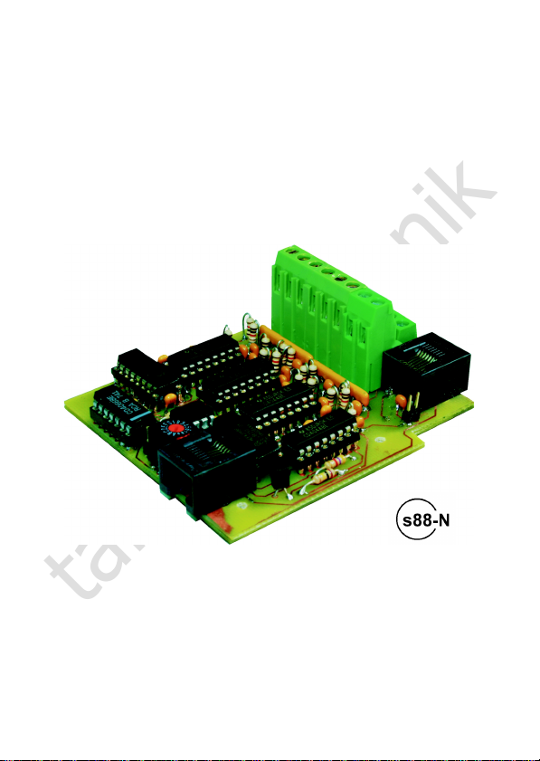
S88-4
Item no. 44-01405 | 44-01406 | 44-01407
s88-Feedback Module
16-fold
tams elektronik
n n n
Page 2

tams elektronik
English S88-4
Table of contents
1. Getting started............................................................................3
2. Safety instructions.......................................................................5
3. Safe and correct soldering...........................................................7
4. Operation overview.....................................................................9
5. Technical specifications..............................................................11
6. Assembling the kit.....................................................................12
7. Connecting the S88-4................................................................19
8. Assigning an address to the S88-4..............................................24
9. Check list for troubleshooting.....................................................27
10. Guarantee bond........................................................................29
11. EU declaration of conformity......................................................30
12. Declarations conforming to the WEEE directive...........................30
© 12/2014 Tams Elektronik GmbH
All rights reserved. No part of this publication may be reproduced or
transmitted in any form or by any means, electronic or mechanical,
including photocopying, without prior permission in writing from Tams
Elektronik GmbH.
Subject to technical modification.
Page 2
Page 3
tams elektronik
!
S88-4 English
1. Getting started
How to use this manual
This manual gives step-by-step instructions for safe and correct
assembly of the kit and fitting and connecting of the ready-built
module, and operation. Before you start, we advise you to read the
whole manual, particularly the chapter on safety instructions and the
checklist for trouble shooting. You will then know where to take care
and how to prevent mistakes which take a lot of effort to correct.
Keep this manual safely so that you can solve problems in the future. If
you pass the kit or the ready-built module on to another person, please
pass on the manual with it.
Intended use
The feedback module S88-4 is designed to be operated according to
the instructions in this manual in model building, especially with model
railways. Any other use is inappropriate and invalidates any guarantees.
The feedback module S88-4 should not be assembled or mounted by
children under the age of 14.
Reading, understanding and following the instructions in this manual
are mandatory for the user.
Caution:
The S88-4 contains integrated circuits. These are very sensitive to
static electricity. Do not touch components without first discharging
yourself. Touching a radiator or other grounded metal part will
discharge you.
Page 3
Page 4

tams elektronik
English S88-4
Checking the package contents
Please make sure that your package contains:
one kit, containing the components listed in the parts list
( page 15) and one PCB or
one ready-built module or
one ready-built module in a housing (complete unit),
an Ethernet patch cable with RJ-45 connectors (length: 0.5 m)
a CD (containing the manual and further information).
Required materials
For assembling the kit you need:
an electronic soldering iron (max. 30 Watt) or a regulated soldering
iron with a fine tip and a soldering iron stand,
a tip-cleaning sponge,
a heat-resistant mat,
a small side cutter and wire stripper,
as necessary a pair of tweezers and long nose pliers,
electronic tin solder (0.5 mm diameter).
In order to connect the module to the rails you need wire.
Recommended diameter: > 0.25 mm².
For the connection of the module to a device with a 6-pole s88
connector you need:
an adapter S88-A (depending on the installation situation item no.
44-09100, 44-09110, 44-09200 or 44-09210).
Page 4
Page 5

tams elektronik
S88-4 English
2. Safety instructions
Mechanical hazards
Cut wires can have sharp ends and can cause serious injuries. Watch
out for sharp edges when you pick up the PCB.
Visibly damaged parts can cause unpredictable danger. Do not use
damaged parts: recycle and replace them with new ones.
Electrical hazards
Touching powered, live components,
touching conducting components which are live due to malfunction,
short circuits and connecting the circuit to another voltage than
specified,
impermissibly high humidity and condensation build up
can cause serious injury due to electrical shock. Take the following
precautions to prevent this danger:
Never perform wiring on a powered module.
Assembling and mounting the kit should only be done in closed,
clean, dry rooms. Beware of humidity.
Only use low power for this module as described in this manual and
only use certified transformers.
Connect transformers and soldering irons only in approved mains
sockets installed by an authorised electrician.
Observe cable diameter requirements.
After condensation build up, allow a minimum of 2 hours for
dispersion.
Use only original spare parts if you have to repair the kit or the
ready-built module.
Page 5
Page 6

tams elektronik
!
English S88-4
Fire risk
Touching flammable material with a hot soldering iron can cause fire,
which can result in injury or death through burns or suffocation.
Connect your soldering iron or soldering station only when actually
needed. Always keep the soldering iron away from inflammable
materials. Use a suitable soldering iron stand. Never leave a hot
soldering iron or station unattended.
Thermal danger
A hot soldering iron or liquid solder accidentally touching your skin can
cause skin burns. As a precaution:
use a heat-resistant mat during soldering,
always put the hot soldering iron in the soldering iron stand,
point the soldering iron tip carefully when soldering, and
remove liquid solder with a thick wet rag or wet sponge from the
soldering tip.
Dangerous environments
A working area that is too small or cramped is unsuitable and can cause
accidents, fires and injury. Prevent this by working in a clean, dry room
with enough freedom of movement.
Other dangers
Children can cause any of the accidents mentioned above because they
are inattentive and not responsible enough. Children under the age of
14 should not be allowed to work with this kit or the ready-built
module.
Caution:
Little children can swallow small components with sharp edges, with
fatal results! Do not allow components to reach small children.
Page 6
Page 7
tams elektronik
!
S88-4 English
In schools, training centres, clubs and workshops, assembly must be
supervised by qualified personnel.
In industrial institutions, health and safety regulations applying to
electronic work must be adhered to.
3. Safe and correct soldering
Caution:
Incorrect soldering can cause dangers through fires and heat. Avoid
these dangers by reading and following the directions given in the
chapter Safety instructions.
Use a small soldering iron with max. 30 Watt or a regulated
soldering iron.
Only use electronic tin solder with flux.
When soldering electronic circuits never use soldering-water or
soldering grease. They contain acids that can corrode components
and copper tracks.
Insert the component connecting pins into the PCB´s holes as far as
possible without force. The components should be close to the
PCB`s surface.
Observe correct polarity orientation of the parts before soldering.
Solder quickly: holding the iron on the joints longer than necessary
can destroy components and can damage copper tracks or soldering
eyes.
Apply the soldering tip to the soldering spot in such a way that the
part and the soldering eye are heated at the same time.
Simultaneously add solder (not too much). As soon as the solder
becomes liquid take it away. Hold the soldering tip at the spot for a
few seconds so that the solder flows into the joint, then remove the
soldering iron.
Do not move the component for about 5 seconds after soldering.
Page 7
Page 8

tams elektronik
English S88-4
To make a good soldering joint you must use a clean and unoxidised
soldering tip. Clean the soldering tip with a damp piece of cloth, a
damp sponge or a piece of silicon cloth.
Cut the wires after soldering directly above the soldering joint with a
side cutter.
After placing the parts, please double check for correct polarity.
Check the PCB tracks for solder bridges and short circuits created by
accident. This would cause faulty operation or, in the worst case,
damage. You can remove excess solder by putting a clean soldering
tip on the spot. The solder will become liquid again and flow from
the soldering spot to the soldering tip.
Page 8
Page 9
tams elektronik
S88-4 English
4. Operation overview
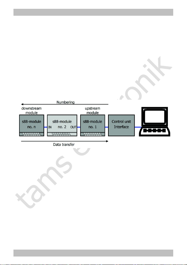
The feedback module S88-4 is compatible with all components working
with the s88-bus developed by the company Märklin**. It can read in
16 mass contacts. This information is transferred via the s88-bus to the
upstream module or to the connected digital unit (interface, memory or
central unit). The data transfer from one feedback module to the other
one works on the principle of the bucket brigade device.
The number of feed back modules to be connected to one bus line
depends on the interface, the memory or the control unit in use. Please
follow the specifications of the device´s manufacturer.
Specific features of the S88-4
According to the standard, the s88 feedback system is mounted by
lining up the feedback modules, comparible to lining up pearls on a
string. On this principle branching bus lines or a radial layout cannot be
put into practice without using special attachments.
The addresses for the standard feedback modules are assigned
automatically, according to the modules´ order. When mounting an
additional standard module between two existing modules, the
succeeding modules will be renumbered automatically. The effort
involved to reprogram the control software in the PC can be
considerable.
Page 9
Page 10

tams elektronik
English S88-4
With the feedback module S88-4 you can assign an address directly.
This minimizes the effort when adding a new module between existing
modules. Addressing the feedback modules S88-4 directly is also the
condition for installing branching bus lines and radial layouts.
It is possible to combine standard modules and S88-4 modules in one
bus system. You have got to be aware that standard feedback modules
can be used in linear data lines connected directly to the control unit or
the interface only and not in branching data lines.
Standard s88-N
The S88-4 has RJ-45 connections according to the standard s88-N,
which regulates the assignment of commercial Ethernet patch-cables
for use in s88 feedback systems. Unlike the 6-conductor connecting
cables frequently used, the patch-cables used in computer networks are
screened against outside electric signals. Thus using patch-cables
reduces the liability to interference considerably.
For the connection of digital devices or customary feedback modules
with a 6-pole connector you need a special adapter (optional extra).
Page 10
Page 11

tams elektronik
S88-4 English
5. Technical specifications
Number of mass contacts 16
Feedback log s88
Connections to the s88-bus
(IN, OUT)
RJ-45 according to S88-N
Supply voltage 5 – 15 V d.c. voltage
(provided by the s88-bus
Protected to IP 00
Ambient temperature in use 0 ... +60 °C
Ambient temperature in storage -10 ... +80 °C
Comparative humidity allowed max. 85 %
Dimensions of the PCB
Dimensions including housing
approx. 72 x 82 mm
approx. 100 x 90 x 35 mm
Weight of the assembled board
Weight including housing
approx. 73 g
approx. 121 g
Page 11
Page 12

tams elektronik
English S88-4
6. Assembling the kit
You can skip this part if you have purchased a ready-built module or device.
Preparation
Put the sorted components in front of you on your workbench.
The separate electronic components have the following special features
you should take into account in assembling:
Resistors
Resistors reduce current.
The value of resistors for smaller power ratings is indicated
through colour rings. Every colour stands for another
figure. Carbon film resistors have 4 colour rings. The 4th
ring (given in brackets here) indicates the tolerance of the
resistor (gold = 5 %).
Value: Colour rings:
220 red - red - brown (gold)
1 k brown - black - red (gold)
4,7 k yellow - violet - red (gold)
15 k brown - green - orange (gold)
100 k brown - black - yellow (gold)
Resistance networks
In resistance networks there are several resistors
integrated. The number of the integrated resistors varies
depending on the design. One side of the resistors is
commonly taken out of the network, the other side
seperately for every resistor.
Page 12
Page 13

tams elektronik
S88-4 English
Ceramic capacitors
Among other things ceramic capacitors are used for
filtering interference voltages or as frequency determining
parts. Ceramic capacitors are not polarized.
Normally they are marked with a three-digit number which
indicates the value coded. The number 104 corresponds to
the value 100 nF.
Diodes and Zener diodes
Diodes allow the current to pass through in one direction
only (forward direction), simultaneously the voltage is
reduced by 0,3 to 0,8 V. Exceeding of the limit voltage
always will destroy the diode, and allow current to flow in
the reverse direction.
Zener diodes are used for limiting voltages. In contrast to "normal"
diodes they are not destroyed when the limit voltage is exceeded.
The diode type is printed on the package.
Transistors
Transistors are current amplifiers which convert low signals into
stronger ones. There are several types in different package forms
available. The type designation is printed on the component.
Transistors for a low power rating (e.g. BC types, BS
types) have a package in form of a half zylinder (SOTpackage). The three pins of bipolar transistors (e.g. BC, BD
and BT types) are called basis, emitter and collector
(abbreviated with the letters B, E, C in the circuit diagram).
Page 13
Page 14

tams elektronik
English S88-4
Integrated circuits (ICs)
Depending on the type, ICs fulfil various tasks. The most
common housing form is the so-called "DIL"-housing, from
which 4, 6, 8, 14, 16, 18 or more "legs" (pins) are
arranged along the long sides.
ICs are sensitive to damage during soldering (heat,
electrostatic charging). For that reason in the place of the
ICs IC sockets are soldered in, in which the ICs are
inserted later.
Microcontrollers
Microcontrollers are ICs, which are individually programmed for the
particular application. The programmed controllers are only available
from the manufacturer of the circuit belonging to it.
Rotary code switches
Rotary code switches can be set to 10 or 16 switching positions with a
small screwdriver, depending on the version.
Terminal strips
Terminal strips are solder-in screw-type terminals. They provide a
solder-free and safe connection of the cables to the circuit, which can
still be separated any time.
RJ-45 sockets
The RJ-45 sockets are standardized and are made to connect
commercial Ethernet patch-cables (or RJ-45 cables).
Page 14
Page 15

tams elektronik
S88-4 English
Parts list
Carbon film resistors R20 220
R4, R5, R6, R7, R8, R9,
R10, R11, R12, R13,
R14, R15, R16, R17,
R18, R19
1 k
R2, R3, R21, R24, R25 4,7 k
R23 15 k
R1, R22 100 k
Resistance networks RN1, RN2 47 k
Ceramic capacitors C1 bis C19 100 nF
Zener diodes D12 6V2
Transistors for a low power
rating
Q1, Q2 BC547B
Integrated circuits (ICs) IC1, IC2 4014N
IC3, IC4, IC5, IC6 4044N
IC7 4066N
Microcontrollers IC8 PIC12F508P
IC-sockets IC1, IC2 , IC3, IC4, IC5,
IC6
16-pole
IC7 14-pole
IC8 8-pole
Terminal strips X1 8-pole
Rotary code switches S1
RJ-45 sockets IN, OUT
Page 15
Page 16

tams elektronik
English S88-4
PCB layout
Page 16
Page 17

tams elektronik
!
S88-4 English
Assembly
Proceed according to the order given in the list below. First solder the
components on the solder side of the PCB and then cut the excess
wires with the side cutter. Follow the instructions on soldering in
section 3.
Caution:
Several components have to be mounted according to their polarity.
When soldering these components the wrong way round, they can be
damaged when you connect the power. In the worst case the whole
circuit can be damaged. At the best, a wrongly connected part will not
function.
1. Resistors R1, R2,
R3, R20, R23
Mounting orientation of no importance.
2. Diodes, Zener
diodes
Observe the polarity!
The negative end of the diodes is marked with
a ring. This is shown in the PCB layout.
3. IC sockets Mount the sockets that way, the markings on
the sockets show in the same direction as the
markings on the PCB board.
4. Resistors
R4 to R19, R21,
R22, R24, R25
Solder the resistor that way, their bodies are
standing upright on the PCB.
Mounting orientation of no importance.
5. Resistance
networks
Observe the mounting orientation!
The common connection is marked which is
also shown on the PCB print.
6. Ceramic
Capacitors
Mounting orientation of no importance.
Page 17
Page 18

tams elektronik
English S88-4
7. Transistors Observe the polarity!
The cross section of transistors for a low
power rating in SOT-packages is shown in the
PCB layout.
8.
Terminal strips
Put together the double terminal strips before
mounting them.
9. Rotary code
switch
Solder in the code switch so that you can
adjust it from the outside after mounting it.
10. RJ-45 sockets
11. ICs in DILhousing
Insert the ICs into the soldered socket.
Do not touch the ICs without first discharging
yourself by touching a radiator or other
grounded metal parts.
Do not bend the "legs" when inserting them
into the sockets. Check that the markings on
the PCB, the socket and the IC show to the
same direction.
Performing a visual check
Perform a visual check after the assembly of the module and remove
faults if necessary:
Remove all loose parts, wire ends or drops of solder from the PCB.
Remove all sharp wire ends.
Check that solder contacts which are close to each other are not
unintentionally connected to each other. Risk of short circuit!
Check that all components are polarised correctly.
When you have remedied all faults, go on to the next part.
Page 18
Page 19

tams elektronik
S88-4 English
7. Connecting the S88-4
The S88-4 has two RJ-45 sockets (IN, OUT) to connect commercial
Ethernet patch-cables (RJ-45 cables), which allow an interference free
connection to other feedback modules or digital devices. Use an
adapter S88-A (optional extra) for the connection of digital devices or
customary feedback modules with 6-pole connector.
There are terminal strips soldered to the inputs and to the earth
connection of the S88-4 which are used to insert and screw on the
connecting wires.
Functional test
First connect the output "OUT" of the S88-4 to the central unit, the
memory or the interface for a functional test. Fix a connecting cable to
the module’s earth connection X2 and connect it one after the other to
all 16 inputs. Check if the correct status message is shown for all
inputs.
Connection to the s88 bus
After successfully terminating the functional test mount the S88-4 at
the desired place in your layout. Connect the inputs 1 to 16 to the mass
contacts, the output OUT to the control unit, the interface or another
feedback module and the input IN to another feedback module, if
necessary.
Unlike with standard feedback modules you can install branching lines
with the S88-4 modules. There are no limits for the layout of the data
lines, everything is possible, from simple branch lines up to radial
layouts. Use special RJ-45 terminal boxes (optional extra) for the
branch connections.
Page 19
Page 20

tams elektronik
English S88-4
Example for a s88 bus system with branching data lines.
Combination with standard feedback modules
You can combine the S88-4 module with standard feedback modules in
a data line directly connected to the control unit or the interface. In this
way you can mount a S88-4 module between existing standard
modules, e.g.
Example for mounting an additional S88-4 module between standard modules. The standard
modules keep the addresses 1 to 3 assigned automatically. The S88-4 module gets the address
4. When adding a standard module between the modules 2 and 3, this would get the address 3
automatically, all following modules would be renumbered.
Page 20
Page 21

tams elektronik
S88-4 English
After branch connections of a data line, seen from the control unit or
the interface, you can use S88-4 modules only.
Example for the combination of standard modules and S88-4 modules in one bus system. The
standard modules can be used in data lines directly connected to the control unit or the
interface only and not in branching data lines.
Earth connection
In systems with continuous mass (e.g. 3 rail systems fed with boosters
with continuous mass) the earth connection between s88 feedback
module and other components is made via the earth line in the s88 bus
cable.
In digital layouts with boosters galvanically separated, the earth
connection X2 of the S88-4 module has to be connected to a separate
earth line or to mass of the rails. This applies especially to layouts with
DCC conform boosters, but as well to layouts controlled by the central
station of Märklin** or the Ecos of ESU**.
Page 21
Page 22

tams elektronik
English S88-4
Pin assignment
IN RJ-45 socket for the connection of
a downstream s88 module
OUT RJ-45 socket or 6-pole connector
for the connection of
an upstream s88 module or digital device
1 … 16 Inputs for mass contacts
1 Example: Connection to a switching rail
7 Example: Connection to a contact rail
13 Example: Connection to a reed contact
X2 Earth connection (if necessary)
Page 22
Page 23

tams elektronik
S88-4 English
Connections diagram
Page 23
Page 24

tams elektronik
English S88-4
8. Assigning an address to the S88-4
According to principle, the standard feedback modules in the s88 bus
get an address automatically according to their position in the data line.
Thus you have to assign addresses to the S88-4 modules which are
higher as the highest address of a standard module. It is up to you to
assign the addresses to the S88-4 modules. The addresses do not have
to be appointed in ascending or descending order. It is possible to leave
addresses unused.
When assigning the addresses be careful not to appoint addresses
already used. In case two modules have the same address only the
data of the module next to the control unit or the interface will be
transmitted.
Take into account how many s88 modules your control unit or interface
supports.
The address of a S88-4 module is set by two parameters:
1. The position of the code switch, set by turning the arrow with a
small srewdriver. The settings 0 to 9 and A to F correspond to the
numerical values 1 to 16 (see list below).
2. The number of standard modules preceding the S88-4 module (not
the total number of standard modules in the s88 bus).
The particular address results from the address of the last standard
module before the S88-4 module plus the numerical value
corresponding to the setting of the code switch.
In consequence, the addresses you can assign to a S88-4 module are
restricted:
1. The lowest possible address is by 1 higher than the number of
standard modules in the s88 bus.
2. The highest possible address ist by 16 higher than the number of
standard modules preceding the S88-4 module.
Page 24
Page 25

tams elektronik
S88-4 English
Setting
Tallies
numerical
value
Address by number of
preceding standard modules
=1 =2 =3 =4 =5 =6 =7 =n
0 1 2 3 4 5 6 7 8 n+1
1 2 3 4 5 6 7 8 9 n+2
2 3 4 5 6 7 8 9 10 n+3
3 4 5 6 7 8 9 10 11 n+4
4 5 6 7 8 9 10 11 12 n+5
5 6 7 8 9 10 11 12 13 n+6
6 7 8 9 10 11 12 13 14 n+7
7 8 9 10 11 12 13 14 15 n+8
8 9 10 11 12 13 14 15 16 n+9
9 10 11 12 13 14 15 16 17 n+10
A 11 12 13 14 15 16 17 18 n+11
B 12 13 14 15 16 17 18 19 n+12
C 13 14 15 16 17 18 19 20 n+13
D 14 15 16 17 18 19 20 21 n+14
E 15 16 17 18 19 20 21 22 n+15
F 16 17 18 19 20 21 22 23 n+16
Page 25
Page 26

tams elektronik
English S88-4
Example for numbering the S88-4 modules. The numbers behind the arrows correspond to the
setting of the code switch.
The S88-4 module with the address 4 cannot get a lower address, as the addresses 1 to 3 are
used by standard modules. The code switch has to be set to "2" as one standard module is
preceding.
The S88-4 modules with the addresses 5, 6, 10 and 11 are preceded by three standard
modules. The address 7, 8 and 9 are not in use in the shown system, which does not influence
the mode of operation.
Page 26
Page 27

tams elektronik
!
S88-4 English
9. Check list for troubleshooting
Parts are getting too hot and/or start to smoke.
Disconnect the system from the mains immediately!
Possible cause: one or more components are soldered incorrectly.
à In case you have mounted the module from a kit, perform a
visual check (à section 6.) and if necessary, remedy the faults.
Otherwise send in the module for repair.
The central unit, the memory or the interface do not show the
proper status.
Possible cause: The connection(s) between the feedback module and
feedback modules connected in series or the digital device are
interrupted. à Check the connections. When using a ribbon cable,
check as well, if the connecting socket of the ribbon cable is put on
in the right direction.
Possible cause: The connection between the input and the mass
contact is interrupted. à Check the connections.
The control unit / the memory / the interface always displays in a
specific situation the same false status.
Possible cause: You have assigned another address to the S88-4
module than required. Check the address.
The control unit / the memory / the interface display does not
display the status of one module.
Possible cause: You have assigned an address to a S88-4 module
that is occupied by another S88-4 module or a standard module.
Check the addresses.
Page 27
Page 28

tams elektronik
English S88-4
Hotline
If problems with your module occur, our hotline is pleased to help you
(mail address on the last page).
Repairs
You can send in a defective module for repair (address on the last
page). In case of guarantee the repair is free of charge for you. With
damages not covered by guarantee, the maximum fee for the repair is
the difference between the price for the ready-built module and the kit
according to our valid price list. We reserve the right to reject the
repairing of a module when the repair is impossible for technical or
economic reasons.
Please do not send in modules for repair charged to us. In case of
warranty we will reimburse the forwarding expenses up to the flat rate
we charge according to our valid price list for the delivery of the
product. With repairs not covered by guarantee you have to bear the
expenses for sending back and forth.
Page 28
Page 29

tams elektronik
S88-4 English
10. Guarantee bond
For this product we issue voluntarily a guarantee of 2 years from the
date of purchase by the first customer, but in maximum 3 years after
the end of series production. The first customer is the consumer first
purchasing the product from us, a dealer or another natural or juristic
person reselling or mounting the product on the basis of selfemployment. The guarantee exists supplementary to the legal warranty
of merchantability due to the consumer by the seller.
The warranty includes the free correction of faults which can be proved
to be due to material failure or factory flaw. With kits we guarantee
the completeness and quality of the components as well as the function
of the parts according to the parameters in not mounted state. We
guarantee the adherence to the technical specifications when the kit
has been assembled and the ready-built circuit connected according to
the manual and when start and mode of operation follow the
instructions.
We retain the right to repair, make improvements, to deliver spares or
to return the purchase price. Other claims are excluded. Claims for
secondary damages or product liability consist only according to legal
requirements.
Condition for this guarantee to be valid, is the adherence to the
manual. In addition, the guarantee claim is excluded in the following
cases:
if arbitrary changes in the circuit are made,
if repair attempts have failed with a ready-built module or device,
if damaged by other persons,
if damaged by faulty operation or by careless use or abuse.
Page 29
Page 30

tams elektronik
English S88-4
11. EU declaration of conformity
This product conforms with the EC-directives mentioned below
and is therefore CE certified.
2004/108/EG on electromagnetic. Underlying standards: EN 55014-1
and EN 61000-6-3. To guarantee the electromagnetic tolerance in
operation you must take the following precautions:
Connect the transformer only to an approved mains socket installed
by an authorised electrician.
Make no changes to the original parts and accurately follow the
instructions, connection diagrams and PCB layout included with this
manual.
Use only original spare parts for repairs.
2011/65/EG on the restriction of the use of certain hazardous
substances in electrical and electronic equipment (ROHS). Underlying
standard: EN 50581.
12. Declarations conforming to the WEEE directive
This product conforms with the EC-directive 2012/19/EG on
waste electrical and electronic equipment (WEEE).
Don´t dispose of this product in the house refuse, bring it to the next
recycling bay.
Page 30
Page 31

tams elektronik
S88-4 English
Page 31
Page 32

tams elektronik
n
n
n
Information and tips:
n
http://www.tams-online.de
n
n
n
n
Warranty and service:
n
Tams Elektronik GmbH
n
Fuhrberger Straße 4
DE-30625 Hannover
n
fon: +49 (0)511 / 55 60 60
fax: +49 (0)511 / 55 61 61
n
e-mail: modellbahn@tams-online.de
n
n
 Loading...