

Page 1
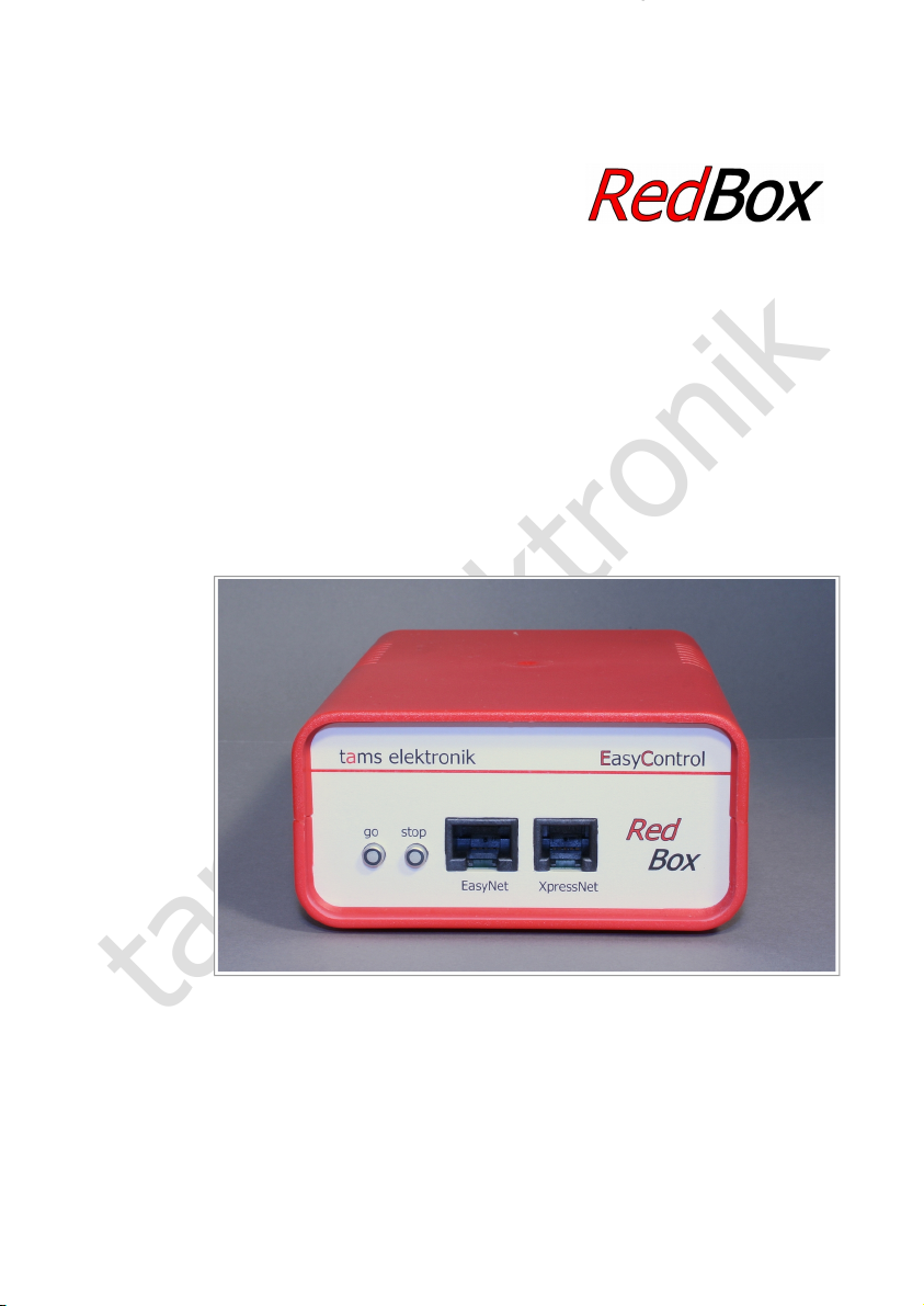
tams elektronik
E D C
Central unit for
digital system EasyControl
Version "Basic" item no. 40-02007
Version "Basic-R" item no. 40-02017
Version "V24" item no. 40-02037
Version"Booster" item no. 40-02057
Version"Booster-R" item no. 40-02067
Manual
tams elektronik
n n n
Page 2

tams elektronik
RedBox English
Seite 2
Page 3

tams elektronik
English RedBox
Contents
1. Getting started................................................................................................................5
2. What is EasyControl?.......................................................................................................7
2.1. Components............................................................................................................7
2.2. EasyNet...................................................................................................................7
2.3. Digital formats.........................................................................................................9
3. Components for the digital system EasyControl................................................................11
3.1. Central unit............................................................................................................11
3.2. Booster.................................................................................................................12
3.2.1. Breaking distance booster ("Breaking booster")..............................................12
3.2.2. Seperating driving and switching...................................................................13
3.3. Non-central control devices.....................................................................................14
3.4. PC, tablet and smartphone.....................................................................................15
3.4.1. Overview PC- and WLAN interfaces of the central unit versions.......................16
3.4.2. Control software...........................................................................................16
3.5. Adapters for other bus systems...............................................................................17
3.6. S88 modules..........................................................................................................17
3.7. DCC programming track.........................................................................................18
4. Connecting external components and the power supply to the RedBox..............................19
4.1. EasyNet interface...................................................................................................20
4.2. XpressNet interface................................................................................................23
4.3. PC interfaces.........................................................................................................24
4.4. WLAN interface......................................................................................................25
4.4.1. Connecting Android devices to the WLAN interface of the RedBox...................25
4.5. External boosters...................................................................................................26
4.6. Integrated booster (versions "Booster" and "Booster-R" only)...................................28
4.6.1. Connecting voltage supply and rails...............................................................29
4.6.2. Configurating the integrated booster..............................................................30
4.6.3. Driving and switching separately with one RedBox..........................................31
4.7. S88 feedback modules...........................................................................................32
4.8. Programming track.................................................................................................33
4.9. Power supply for control devices.............................................................................33
5. Adjusting parameters of the digital control......................................................................35
6. Operation......................................................................................................................39
6.1. Switching on / off...................................................................................................39
6.2. Plug and play.........................................................................................................39
6.3. LED displays on the front side.................................................................................40
6.4. LED displays on the rear side (versions "Booster" and "Booster-R" only)....................40
Seite 3
Page 4

tams elektronik
RedBox English
7. Update..........................................................................................................................41
8. Check list for troubleshooting.........................................................................................42
8.1. Errors occurring while starting up............................................................................42
8.2. Errors occurring while setting parameters................................................................42
8.3. Errors occurring while operating..............................................................................42
8.4. Errors occurring during software update..................................................................43
9. Technical Specifications..................................................................................................44
9.1. RedBox..................................................................................................................44
9.2. Integrated Booster (Versions "Booster" and "Booster-R")..........................................45
10. Background information.................................................................................................46
10.1.Motorola-Format....................................................................................................46
10.2.DCC-Format...........................................................................................................47
10.3.m3........................................................................................................................49
10.4.s88.......................................................................................................................49
10.5.RailCom.................................................................................................................50
10.6.Boosters................................................................................................................51
11. The asterisks **.............................................................................................................52
12. Guarantee bond.............................................................................................................53
13. EU declaration of conformity...........................................................................................54
14. Declarations conforming to the WEEE directive................................................................54
© 06/2018 Tams Elektronik GmbH
All rights reserved. No part of this publication may be reproduced or transmitted in any form or
by any means, electronic or mechanical, including photocopying, without prior permission in
writing from Tams Elektronik GmbH.
Subject to technical modification.
Seite 4
Page 5

tams elektronik
English RedBox
1. Getting started
Checking contents
Please make sure that your package contains:
RedBox
power pack (12 V AC / 1,6 A)
cable to connect a DCC programming track
versions "Booster" and "Booster-R" only:
3 short-circuit jumpers
2 plug-in parts for terminal strips
compact disc containing manual, USB-driver (Tams-ID) and demo software
Required auxiliary devices
For operating the digital control you need auxiliary devices (not included in the scope of
delivery):
for versions "Basic", "Basic-R" and "V24": at least one external booster and an appropriate
power supply
for versions "Booster" and "Booster-R": one transformer or power supply unit. Hint: The
required output depends on the rail voltage set for the integrated booster. ( à section 4.6.1.
"Connecting voltage supply and rails")
one input and display device:
one EasyControl device with software version from 2.0
(e.g. LokControl, HandControl, HandControl 2) or
a PC with control software or software CV-Navi or
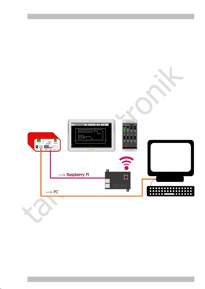
an Android smartphone or tablet with app "EasyControl Android" and a Raspberry Pi
with WLAN router (e.g. wControl)
Seite 5
Page 6

tams elektronik
RedBox English
Saftey instructions
The RedBox should only be used in concordance with these instructions to control digital model
railroad layouts. It is not suitable for use by children under 14. Incorrect use and nonobservance of the manul can be dangerous. In particular there is a risk of electric shock through
contact with metal parts under power, especially when an incorrect voltage is used, or when
operated in a too humid or wet environment. Therefore the following precations should be
observed:
Wiring should only be carried out when the control is disconnected.
Only operate indoors in a dry environment.
Only use proprietry transformers with the correct voltage.
Only connect the transformer in an authorised manner to the house power supply.
Use adequetly thick cable for all wiring. Too thin a cable can overheat.
If the layout is exposed to condensation, allow at least two hours for drying out.
Use only original spare parts if you have to repair the kit or the ready-built module.
Seite 6
Page 7

tams elektronik
English RedBox
2. What is EasyControl?
EasyControl is a digital control for your model railroad layout, which is assembled from different
components. This modular design principle allows you to adjust it to various demands and
differently sized model railway layouts.
2.1. Components
It consists of at least
one digital central unit RedBox (available since 09-2016) or MasterControl (available from
2005 to 2016)
one external booster (not required with RedBox versions "Booster" and "Booster-R")
one external control device (not required with MasterControl)
In addition to your central unit RedBox or MasterControl you can use more than 60 additional
control devices or adapters in one digital control. The following devices are suitable:
EasyControl devices (e.g. LokControl, HandControl, HandControl 2)
digital control devices for bus systems of other manufacturers (e.g. XpressNet)
PC
mobile Android terminal devices (e.g. smartphone, tablet)
DECT-teleohones
digital central units of other manufacturers for Motorola- and/or DCC-format
à section 3. Components for digital control system EasyControl
2.2. EasyNet
External control devices or adapters and the central units RedBox or MasterControl communicate
via the data bus EasyNet. They can be plugged in or out at any time to the EasyNet, even during
operation (plug and play). As a bus line for the EasyNet patch cables with RJ 45 connectors ar
used.
One additional control device or adapter can be connected directly to the EasyNet interface of
the RedBox or the MasterControl. You need a junction (e.g. wye junction or BusControl), if you
want to connect more than one additional device (as far as the device concerned does not have
two RJ 45 connectors, like SniffControl or PhoneControl).
Seite 7
Page 8
tams elektronik
RedBox English
3
6
1
1
4
2
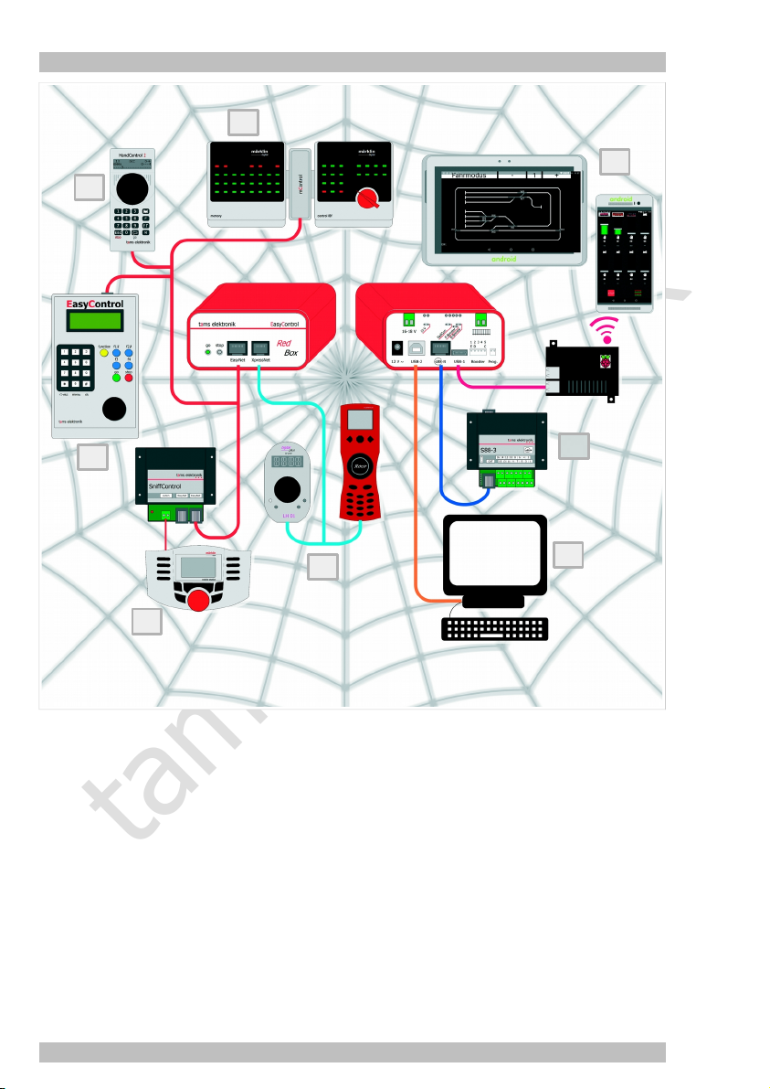
Examples of external control devices and feedback modules to be connected to a
RedBox:
1. EasyControl control devices (e.g. LokControl, HandControl 2)
2. Digital central units of other manufacturers for Motorola- and/or DCC-format (e.g. Maerklin
Mobile Station): connection via SniffControl
3. Older digital control devices for Maerklin Control Unit: connection via mControl
4. Digital control devices for XpressNet (e.g. Lenz LH01, Roco Multimaus)
5. PC
6. mobile Android terminal devices via Raspberry Pi with WLAN router (e.g. wControl). Hint:
The versions "Basic-R" and "Booster-R" have an integrated Raspberry Pi with WLAN router,
there is no need for an additional wControl.
7. s88-feedback modules
7
5
Seite 8
Page 9
tams elektronik
English RedBox
2.3. Digital formats
EasyControl is a multi protocol control system and capable to control vehicle and accessory
decoders of any manufactures compatible with these formats:
Motorola I ("old" Motorola format)
Motorola II ("new" Motorola format)
DCC (complying to NMRA and RCN standards)
Moreover you can use the m3-format to control vehicle decoders designed for mfx-format.
Feedback data sent in mfx-format cannot be analysed by the digital system EasyControl.
EasyControl allows to operate vehicles with Motorola, DCC or mfx decoders in parallel.
You make the setting for whether operating solenoid accessory decoders in the Motorola or DCC
format either
commonly for all connected decoders or
seperately for a group of four decoders.
à Section 10. Background information
RailCom
EasyControl supports the feedback standard RailCom. EasyControl devices, mobile terminal
devices and the PC allow you to enter commands to read out the CV values of decoders
compatible to RailCom. In order to collect and analyse feedback data, you need special RailCom
detectors.
à Section 10. Background information
Decoder addresses , speed levels, switchable functions
Depending on the data format you have the following possibilities for controlling vehicle and
accessory decoders:
Motorola DCC m3
Vehicle decoder addresses 255 10.239 16.384
Amount of speed levels 14 or 27 14, 28 or 128 128
Functions
Accessory decoder addresses 1.020 2.040 –-
function (light)
f1 bis f4
f0 to f28
or to 32.768
f0
f1 to f15
Seite 9
Page 10

tams elektronik
RedBox English
27 speed levels with the Motorola format
As a standard, the Motorola format supports 14 speed levels. EasyControl additionally offers two
methods to extend those speed levels to 27.
Speed level mode 27a: Some decoders (e.g. Maerklin 6090x and Maerklin mfx decoders) support
27 speed levels using the so called interspeed levels. To reach an interspeed level you switch to
a higher speed level and immediately switch back. A power failure will cause the loss of this
speed information data. Your MasterControl simulates those 27 speed levels and shows them in
the display. The MasterControl creates the interspeed levels by regularly switching to a higher
speed level for a short time. This ensures that the speed levels are correctly set even after a
power failure. Normally, the change between speed levels is not visible.
Speed level mode 27b: Using free bit combinations in the function’s double bit helps realizing
proper 27 speed levels. The decoder must support this (e.g. locomotive decoders of Tams
Elektronik and ESU). When controlling locomotive decoders that only support 14 speed levels or
the speed level mode 27a with speed level mode 27b, only every second set speed level actually
changes speed.
Programming modes in the DCC format
RedBox and MasterControl have connections for a programming track which allows to read out
and programm DCC vehicle decoders.
The programming modes to be used and the paremeters to be set depends on the particular
decoder (see decoders´s manual). EasyControl supports programming and reading data in the
following DCC programming types:
CV-programming – byte wise and bitwise
Register and Page programming
Main track programming (POM)
à Section 10. Background information
Programming of mfx vehicle decoders
When setting vehicles with mfx decoders onto the programming track, you can
read out the UID
and program the address
Programming of Motorola vehicle decoders
It is not possible to program Motorola vehicle decoders on the programming track, as this
method is not intended for use with the Motorola format. For that reason you have to program
Motorola decoders according to the manufacturer specifications on the main track.
à Section 10. Background information
Seite 10
Page 11

tams elektronik
English RedBox
3. Components for the digital system EasyControl
3.1. Central unit
As a central unit you can use either a RedBox or a MasterControl (with function "central unit").
The central units RedBox and Master Control
send control instructions to every kind of decoder on your layout,
check for components plugged into the EasyNet,
poll for data and control instructions from components of the EasyControl,
send data to components of the EasyControl,
receive feedback data of s88 modules and transfer them to the PC,
are the interfaces between computer(s) and model railroad layout.
Database for system parameters
RedBox and MasterControl have an integrated database to store all parameters relevent for the
digital system:
booster configuration (short circuit polarity, short circuit sensitivity)
output of commands for accessory decoders at the booster outputs
standard data format for vehicle decoders
switching times for solenoid decoders (minimum/maximum)
RailCom support
number of connected s88 modules
length of signal pause for Motola vehicle decoders
Locomotive database
RedBox and MasterControl have an integrated database to store parameters you apply to a
locomotive’s address, which are:
data format
amount of speed levels
(locomotive’s) name. Example: A locomotive of type BR 89 is assigned address "89" and the
name "EMMA". When applying names to locomotive addresses, you can find a locomotive by
looking for it´s name in the database.
Entering and modifying data
In order to display, enter and modify the system parameters or the data of vehicle decoders,
you need:
MasterControl or
LokControl, HandControl or HandControl 2 (software version 2.0 or higher) or
PC with software CV-Navi or control software supporting EasyControl or
Raspberry Pi (or wControl) and Android smartphone or tablet with app "EasyControl Android"
With the central unit RedBox you cannot display, enter or modify system parameters.
Seite 11
Page 12

tams elektronik
RedBox English
3.2. Booster
Each central unit needs at least one booster. With larger layouts you normally need several
boosters, connected to separate sections of the layout. The required number of boosters
depends on the power requirements of the layout and the amount of current the booster can
provide.
Booster outputs
RedBox: one output for the connection of external boosters (either Maerklin compatible or
DCC conform)
MasterControl: two outputs for the connection of external boosters (either Maerklin
compatible or DCC conform). As both interfaces have to be programmed in common, you
have to use boosters of the same type for both outputs. It is recommended to use boosters
identical in construction.
Integrierted booster
The versions "Booster" and "Booster-R" of the RedBox have an integrated 2.5 A booster (in
addition to the booster output). This is sufficient for operating a small layout (up to nominal size
H0).
MasterControl and the versions "Basic", "Basic-R" and "V24" of the RedBox do not have
integrated boosters. With these central units you have to connect at least one external booster.
3.2.1. Breaking distance booster ("Breaking booster")
Besides the standard booster output, the MasterControl has a second booster output ("breaking
booster"), which can be used to control all breaking distances on your layout. Every Maerklin**compatible booster or booster for the DCC system can be used as breaking booster. As both
interfaces have to be programmed in common, you have to use boosters of the same type for
both outputs. It is recommended to use boosters identical in construction.
The integrated booster of the RedBox (versions "Booster" and "Boster-R") can be configurated
for use as breaking booster.
As soon as one of the locomotives enters a breaking distance, the booster receives a stop signal,
no matter which speed was set. All other data such as the status of the decoder functions and
the driving direction are still sent by the central unit.
Seite 12
Page 13
tams elektronik
English RedBox
3.2.2. Seperating driving and switching
As a standard, the commands to control the vehicle decoders are sent continuously via the
central unit´s booster output, whereas the commands to control the accessory decoders are
sent only when required. For that purpose the transmission of vehicle decoder commands is
interrupted shortly, to transfer the accessory decoder commands during the resulting cutout.
In PC controlled (larger) layouts, this kind of data transfer can cause problems, e.g. when
vehicle decoders receive stop commands too late and this results in locomotives passing stop
signals. Usually two central units are used to solve this problem. They control vehicle and
accessory decoders separately (and are controlled by the PC software accordingly).
With MasterControl and RedBox you can switch off the transmission of accessory decoder
commands at the booster output. Then, only vehicle decoder commands will be transferred and
the delay caused by the transmittsion of accessory decoder commands is excluded.
That way, MasterControl and RedBox (versions "Booster" and "Booster-R") allow to control
vehicle and accessory seperately with one central unit.
MasterControl: Controlling the vehicle decoders via the standard booster output (accessory
decoder commands switched off) and controlling the accessory decoders via the breaking
distance booster output.
RedBox versions "Booster" and "Booster-R": Controlling the vehicle decoders via the booster
output for external boosters (accessory decoder commands switched off) and controlling the
accessory decoders via the integrated booster.
There is no need for adapting the control software. You have to register only one central unit for
this application.
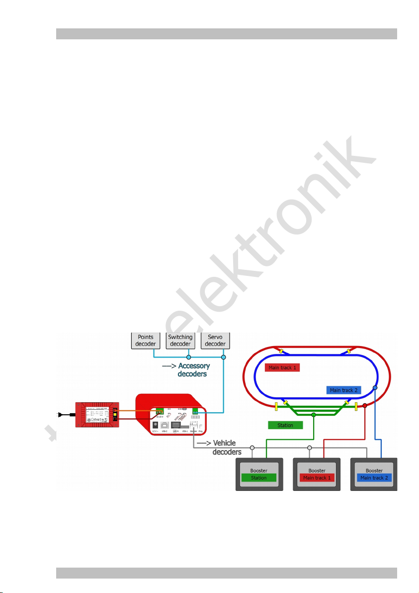
Figure: Seperating driving and switching with one RedBox (versions "Booster" or "Booster-R).
The integrated booster controls the accessory decoders, digital commands for the vehicles
decoders are sent via the external boosters only.
Seite 13
Page 14

tams elektronik
RedBox English
3.3. Non-central control devices
Non-central control devices (such as external devices for the system EasyControl, XpressNet
devices or central units of other manufacturers) offer the possibility to control your model
railroad from different spots and / as well as together with others. They can be plugged in or out
at any time to the EasyNet, even during operation. An EasyNet can handle more than 60 noncentral control units, adapters or similar.
When connecting non-central control devices to the EasyNet, restrictions concerning the
controllable digital formats are cancelled. As an example vehicle decoders designed for Motorola
or mfx format can be controlled with pure DCC devices. In case the decoder´s amount of speed
levels set int the locomotive data base does not correspond to the amount which can be set at
the non-central device, the central unit converts the speed levels internally. The number of
switchable functions and selectable addresses corresponds to the device´s hardware
specification.
You can only use one RedBox or MasterControl (function "control unit") in one digital control. If
required, you can use one or several (additional) MasterControls as non-central control devices,
when operated by a modified software.
Seite 14
Page 15
tams elektronik
English RedBox
3.4. PC, tablet and smartphone
The versions "Basic", "Booster" and "V24" of RedBox as well as MasterControl have each two
interfaces for the (simultaneous) connection of two computers. The versions "Basic-R" and
"Booster-R" of the RedBox have one PC-interface each.
You can integrate up to 32 mobile Android terminal devices (tables, smartphones) into the digital
system EasyControl for use as wireless control devices. You can establish the WLAN connection
with:
customary single-board computer Raspberry Pi 3 with integrated WLAN or Raspberry Pi 2 and
additional WLAN-router
wControl (item no. 40-09957). wControl consists of a single-board computer Raspberry Pi 3
model B and a micro SD-card preconfigured for use as WLAN interface in the system
EasyControl.
RedBox versions "Basic-R" or "Booster-R" with integrated single-board computer Raspberry
Pi 3.
Figure: Integrating PC and mobile terminal devices (here: via an external WLAN interface
wControl)
Seite 15
Page 16
tams elektronik
RedBox English
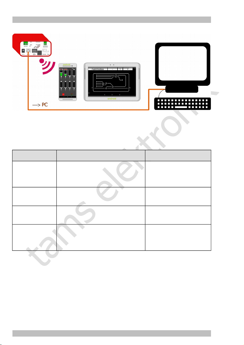
Figure: Integrating PC and mobile terminal devices (here: via the integrated WLAN interface of
the RedBox version "Booster-R")
3.4.1. Overview PC- and WLAN interfaces of the central unit versions
PC interfaces WLAN interfaces
MasterControl one serial interface
(baud rate adjustable)
one USB interface with SiLabs identifier
RedBox "Basic"
RedBox "Booster"
RedBox "Basic-R"
RedBox "Booster-R"
RedBox "V24" one serial interface
USB-1 type Mini-B with Tams identifier
USB-2 type B with SiLabs identifier
USB-2 type B
with SiLabs identifier
(baud rate adjustable)
one USB interface with Tams identifier
external WLAN interface
required
external WLAN interface
required
integrated Raspberry Pi 3
preconfigured for EasyControl
external WLAN interface
required
3.4.2. Control software
Every software, which supports the Märklin** 6050 or P50X protocol is able to control your
RedBox or MasterControl.
In order to use a tablet or smartphone as a wireless control device, you have to install an app on
your mobile terminal device.
Seite 16
Page 17
tams elektronik
English RedBox
3.5. Adapters for other bus systems
Digital devices of other manufacturers using other bus systems than EasyNet for data transfer
can be integrated into the system EasyControl and used for controlling and switching vehicle and
accessory decoders. Your RedBox has an integrated XpressNet interface for the connection of up
to 16 XpressNet devices.
There are different adapters available for the connection of devices of other manufacturers:
Device to be connected Adapter
DECT telephones PhoneControl
XpressNet devices of all manufactureres XNControl
Hint: Your RedBox has an integrated XpressNet interface for
the connection of up to 16 XpressNet devices.
Motorola and DCC digital control devices
of all manufactureres
Older digital control devices for the Maerklin**
Control Unit (item no. 6020 and 6021)
SniffControl
mControl
Hinwes: mControl replaces Maerklin** Control Unit item no.
6020 or 6021.
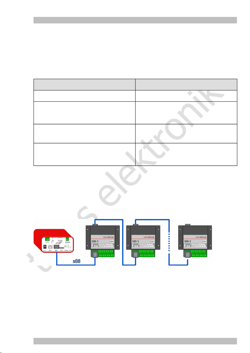
3.6. S88 modules
You can connect up to 52 s88 feedback devices or s88-compatible modules with 832 contacts to
one RedBox or MasterControl. Modules of all manufacturers can be integrated.
The RedBox has a s88 interface according to standard s88-N (for the connection of a patch
cable), the MasterControl a 6-pole interface.
Figure: Connecting s88 modules (max. 52 with 832 contacts)
Seite 17
Page 18

tams elektronik
RedBox English
3.7. DCC programming track
RedBox and MasterControl have a connection for a DCC programming track. Every common rail
can be used for that.
For the decoders of vehicles set onto the programming track you can
in DCC format: read out and program the CVs
in m3 format (for mfx decoders): program the address and read out the UID
Seite 18
Page 19

tams elektronik
English RedBox
4. Connecting external components and the power supply to the RedBox
RedBox | Front side
RedBox "Basic" | Rear side RedBox "Basic-R" | Rear side
RedBox "Booster" | Rear side RedBox "Booster-R" | Rear side
RedBox "V24" | Rear side
Seite 19
Page 20

tams elektronik
RedBox English
4.1. EasyNet interface
You can integrate more than 60 non-central control devices or adapters for devices of other
manufacturers into the digital system via the EasyNet interface on the front side of your RedBox.
Any (RJ 45) Ethernet patch cable (used in Computer networks) will work. Please also read the
manual of your control device or adapter.
You can connect one device or adapter directly to the EasyNet interface of your RedBox. You
need a distributor (Y-distributor for Ethernet patch cables or BusControl) when using more than
one additional device. Exceptions are devices with two EasyNet interfaces, e.g. SniffControl,
XNControl.
The power supply of the RedBox is sufficient to supply four additional devices. When connecting
more devices, you need a BusControl and an additional AC power pack.
EasyControl devices
Please note, that all EasyControl devices must have the same software version as the RedBox to
prevent malfunction of data transfer between the devices.
Other manunfacturer´s digital controls and DECT telephones
Adapters, connected to the EasyNet interface of your RedBox, allow to integrate all Motorola
and/or DCC central units made by other manufacturers, and digital devices for other bus
systems into the digital system, and to use them as external control devices.
Restrictions of digital central units concerning the usable digital formats are overcome, e.g. you
can control vehicle decoders designed for Motorola or mfx format with pure DCC devices. In
case the number of speed levels defined for a decoder in the locomotive data base does not
correspond to the number of speed levels to be set at the device, the RedBox converts the
speed levels internally.
Please note, that with some devices the input options are restricted (e.g. number of switchable
functions, length of locomotive addresses, input of accessory decoder commands).
Seite 20
Page 21

tams elektronik
English RedBox
Device to be connected Adapter
DECT telephone PhoneControl
XpressNet devices from all manufacturers, e.g.
Roco** Lokmaus 2 and 3, Multimaus (not
Lokmaus 1)
handheld controllers by Lenz**
handheld controllers by Massoth**
Motorola and DCC digital central units from all
manufacturers
Older digital devices for digital Control Unit by
Märklin** (item no. 6020 and 6021), e.g.
Keyboard (item no. 6040)
Memory (item no. 6043)
Control panel Control 80 (item no. 6035)
and 80F (item no. 6036)
Infra Control 80 f (item no. 6070)
XNControl
Hint: The RedBox has an integrated XpressNet interface for
the connection of a maximum of 16 XpressNet devices.
Hint: As a power supply for the connected devices you need a
DC or AC power pack (e.g. item no. 70-09110).
SniffControl
mControl
Hint: The mControl replaces Märklin** Control Unit item no.
6020 or 6021.
Hint: As a power supply for the connected devices you need a
DC or AC power pack (e.g. item no. 70-09110).
Figure: Connecting EasyControl devices and DECT telephones (from left to right):
LokControl
MasterControl (with software "MC-Control")
HandControl 2
DECT telephone (via PhoneControl)
Seite 21
Page 22

tams elektronik
RedBox English
Figure: Connecting other manunfacturer´s digital controls to the EasyNet interface (from left to
right):
Märklin Mobile Station or other Motorola- and/or DCC-central units via SniffControl
Digital devices for Märklin Control Unit 6020 and 6021 via mControl: The Märklin** Control
Unit is replaced by mControl and RedBox..
Hint: SniffControl has two EasyNet interfaces. For that reason there is no need for an extra
distributor to connect an additional device.
Seite 22
Page 23

tams elektronik
English RedBox
4.2. XpressNet interface
The XpressNet interface on the front side of the RedBox allows to connect a maximum of 16
XpressNet devices directly to the RedBox(e.g. Roco** Lokmaus 2 and 3, Roco** Multimaus,
handheld controllers by Lenz** and Massoth**) and to use them as external control devices.
Restrictions of the devices concerning the usable digital formats are overcome, e.g. you can
control vehicle decoders designed for Motorola or mfx format with pure DCC devices. In case the
number of speed levels defined for a decoder in the locomotive data base does not correspond
to the number of speed levels to be set at the device, the RedBox converts the speed levels
internally.
Please note, that with some devices the input options are restricted (e.g. number of switchable
functions, length of locomotive addresses, input of accessory decoder commands).
Figure: Connecting XpressNet devices
Direct connection of a maximum of 16 XpressNet devices via the XpressNet interface.
As an alternative or an addition, XpressNet devices can be connected via a XNControl
connected to the EasyNet interface.
Seite 23
Page 24

tams elektronik
RedBox English
4.3. PC interfaces
Depending on the version, your RedBox has:
"Basic", "Booster" and "V24": two galvanically isolated PC interfaces, for parallel connection of
two computers.
"Basic-R" and "Booster-R" with integrated WLAN interface: one USB interface
By means of a PC you can
make software updates for the RedBox
set parameters for the RedBox (e.g. with software CV-Navi)
control the layout (with a suitable PC software)
Versions with two USB- interfaces: RedBox "Basic" and "RedBox "Booster"
USB-1: type Mini-B with Tams identifier
USB-2: type B with SiLabs identifier
There are no specifications according to the assignment of computer(s) to the two interfaces.
Preferably you should connect a computer not operated by Windows or a Raspberry Pi to the
interface USB-1.
When using interface USB-1 for a computer operated by Windows, you have to install a driver
software from the CD on your computer before the first use. In case it is not possible to install a
driver software with Tams identifier for this computer, you should use interface USB-2. Normally,
the driver software for this interface will be installed autamatically when used for the first time
(from Windows 7).
Versions with one USB-interface: RedBox "Basic-R" and "RedBox "Booster-R"
The versions "Basic-R" and "Booster-R" have one USB interface (USB-2) of type B with SiLabs
identifier. Normally, the driver software for this interface will be installed autamatically, when
used for the first time (from Windows 7).
Serial interface: RedBox "V24"
The version "V24" of the RedBox has a serial interface and an USB interface with Tams
identifier. The serial interface is for use with control software controlling the interfaces COM1
and COM2 only, and or for use with PCs not providing an USB interface.
Seite 24
Page 25

tams elektronik
English RedBox
4.4. WLAN interface
Integrating mobile terminals
You can simultaneously operate a maximum of 32 Android smartphones or tablets in one system
EasyControl. If you want to use mobile terminals as wireless control devices with the versions
"Basic", "Booster" and "V24" of the RedBox you need an extra WLAN Interface:
a commercial single-board computer Raspberry Pi 2 and an extra WLAN router or
a commercial single-board computer Raspberry Pi 3 with integrated WLAN router or
an interface "wControl" (item no. 40-09957) with preconfigured Raspberry Pi 3
You should preferably connect the WLAN interface to the interface USB-1 of the RedBox.
The versions "Basic-R" and "Booster-R" of the RedBox have an integrated WLAN interface.
Required software ("app")
You need the app "EasyControl Android" for the mobile terminal(s) which can be downloaded
from the Google Playstore (free trial version, price for the full version: 5,99 € | status: 12/2016).
4.4.1. Connecting Android devices to the WLAN interface of the RedBox
The Versions "Basic-R" and "Booster-R" have an integrated WLAN interface which has been
preconfigured for operation in the EasyNet.
Switching on
Within one minute after switching on the power supply for the RedBox "Basic-R" or "Booster-R"
the WLAN is available.
Connecting a mobile terminal with the wControl
Activate on your smartphone or tablet the list with available WLAN networks under "settings".
Connect you mobile terminal to the network "EasyControl_Android" and enter the following
password for this network:
EasyControl
Pay attention to the upper and lowercase letters when entering the password.
Hint: Your smartphone or tablet automatically restores the connection to the latest chosen
WLAN when restarted.
Downloading the control software
Download the software from the Google Playstore.
The IP-Adresse of the WLAN (192.168.42.1) is preset in the software EasyControl Android. In
case the setting has been overwritten, you have to enter it manually.
Seite 25
Page 26
tams elektronik
RedBox English
4.5. External boosters
To use the version "Basic", "Basic-R" or "V24" you need to connect at least one booster to the
booster interface of the RedBox. Every Märklin**-compatible booster or booster for the DCC
system can be used. Please observe the booster manual.
Please note: Both types of boosters differ regarding short circuit polarity. Yet to be able to use
both types of boosters, the short circuit polarity can be set in the system configuration of the
RedBox. As this setting applies to all connected boosters, only one type of booster may be
connected to your RedBox. Generally, it is recommended to use identically constructed boosters
for supplying the different sections of a circle, in order to avoid problems when crossing the
separations between sections.
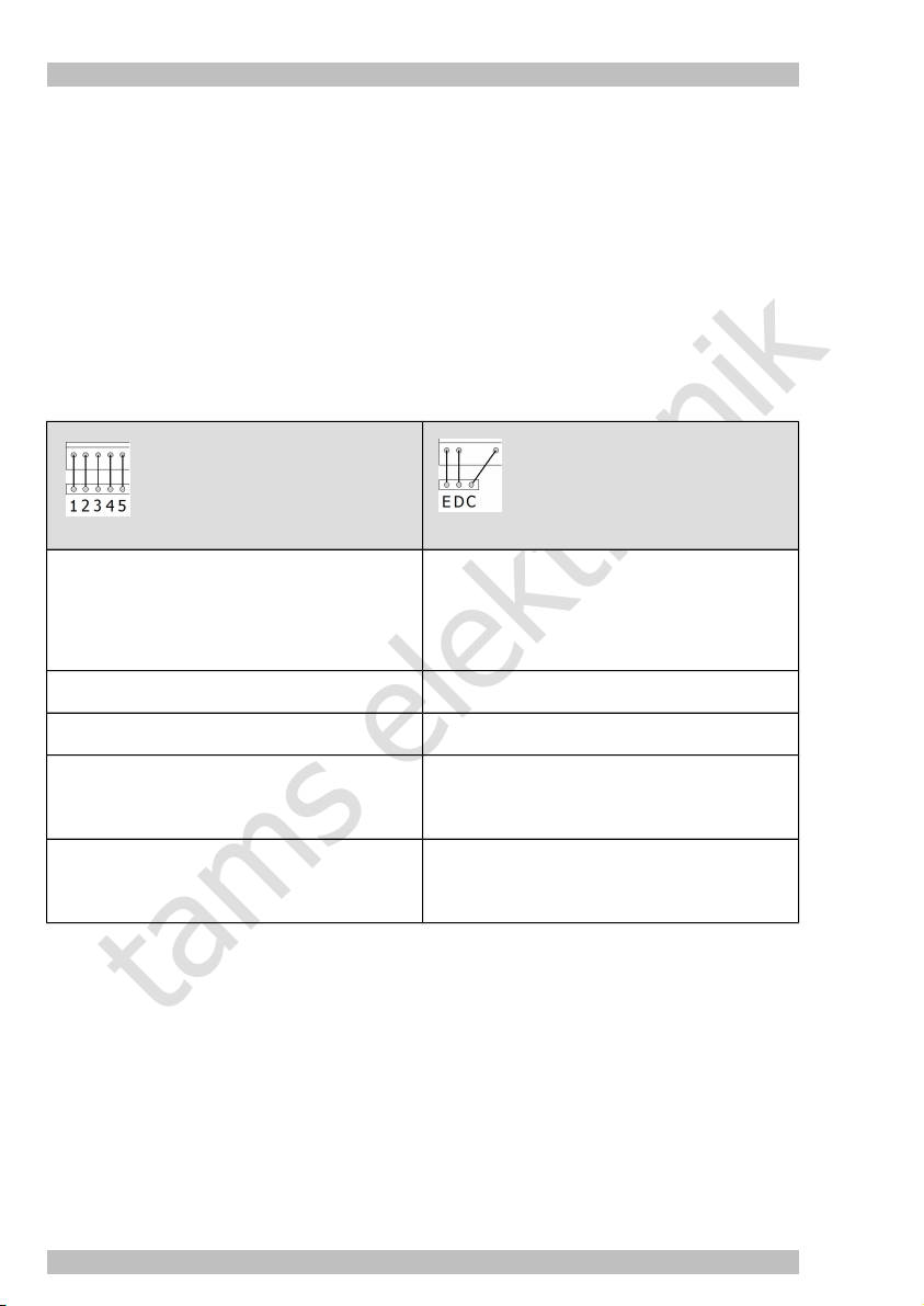
Pin assignment of the booster interface
Märklin**-compatible
booster interface
1 Short circuit feedback.
When the booster detects a short circuit (or in otherwords a
too high current consumption), it reports this to the central
unit. Thereupon the central unit switches off the booster and
displays a short circuit.
2 Ground D Ground
3 no function
4 Booster "on / off"
= output signal for switching on and off Märklin-compatible
boosters
5 Data
= output signal (track signal) for controlling vehicle and
accesory decoders
Special features of the RedBox versions "Booster" and "Booster-R"
The integrated booster and the interface for the connection of external boosters are completely
separated. When using the integrated booster exclusively for supplying a separate layout part,
as braking booster or for controlling accessory decoders, you can use Märklin compatible or DCC
boosters as external boosters (exactly as with the version "Basic", "Basic-R" and "V24").
When using external boosters as a supplement for the integrated booster (supplying several
booster sections of the same layout), you should use boosters B-3 (item no. 40-19327), as these
boosters are identically constructed as the integrated booster. With other booster types, short
circuits or interferences with data transfer possibly occur when crossing the separations between
booster sections.
E Short circuit feedback.
When the booster detects a short circuit (or in otherwords a
too high current consumption), it reports this to the central
unit. Thereupon the central unit switches off the booster and
displays a short circuit.
C Data
= output signal (track signal) for controlling vehicle and
accesory decoders
Booster interface
for DCC system
Seite 26
Page 27

tams elektronik
English RedBox
Figure: Supplying several booster
sections of one layout. As a supplement
for the booster integrated in the
versions "Booster" or "Booster-R" two
boosters B-3 are used.
Seite 27
Page 28

tams elektronik
RedBox English
4.6. Integrated booster (versions "Booster" and "Booster-R" only)
Attention:
!
Be careful to allow the air to flow unhindered through the ventilation slits in the housing of the
RedBox, otherwise the integrated booster possibly overheats. Risk of fire! Make sure to keep
distance to other devices, walls, and similar when connecting your RedBox.
Technical specification of the integrated booster
Supply voltage Separate transformer or separate switching power supply, output
voltage depending on the set track voltage
Track voltage set
15 V 12 - 15 V 17 - 18 V
19 V 16 - 18 V 21 – 22 V
Output voltage 15 or 19 volts digital voltage (regulated)
Power consupmtion max. 48 watt
Maximum output current 2,5 A
Data formats
Feedback log RailCom (RailCom cutout can be switched off)
Output signal symmetrical
LED display
A LED on the rear side of the RedBox shows the operating mode of the integrated booster.
→ Section 6.3.: LED display on the rear side
DCC, Motorola
mfx (vehicle decoder commands only)
Output voltage of the transformer
AC voltage DC voltage
Seite 28
Page 29
tams elektronik
English RedBox
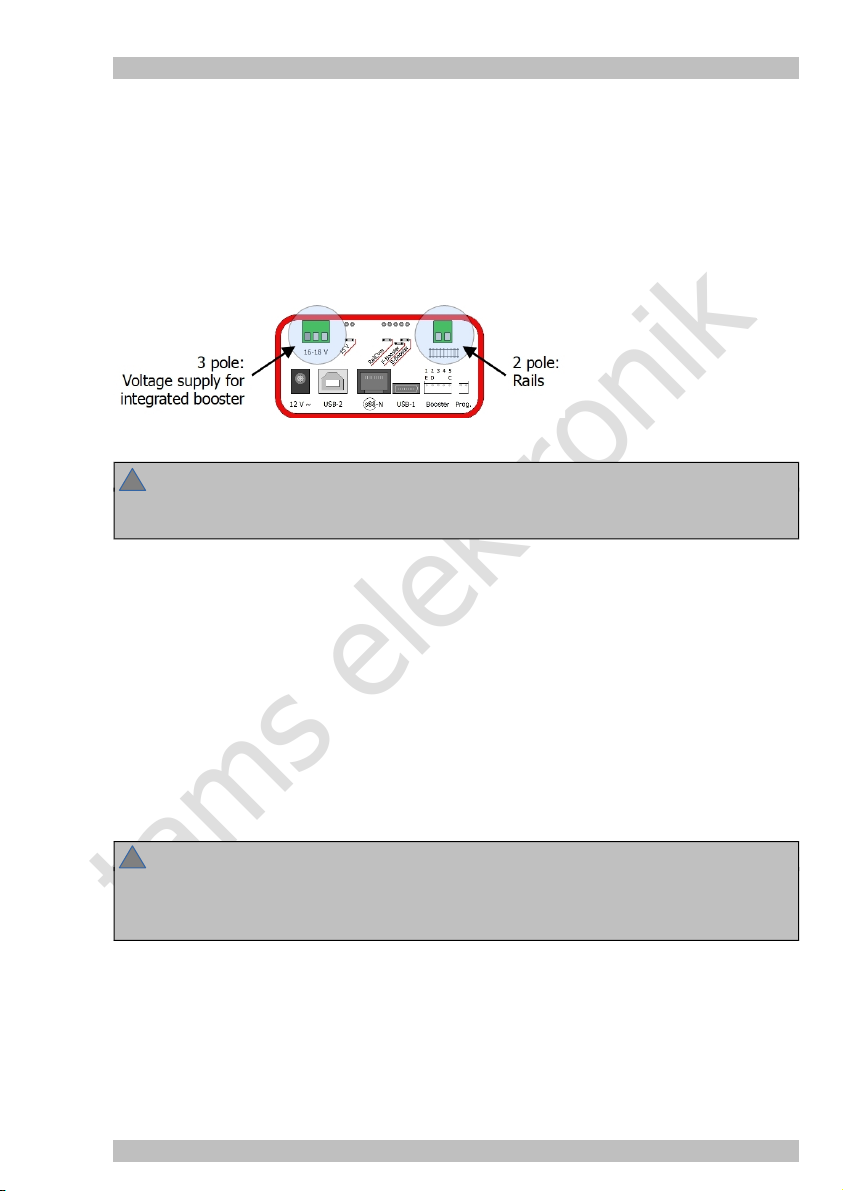
4.6.1. Connecting voltage supply and rails
There are plug-in type terminals for connecting voltage supply and rails on the rear sides of the
versions "Booster" and "Booster-R". Insert the connecting cables into the plug-in parts (included
in delivery), tighten the screws and insert them into the socket parts on the rear side of your
RedBox.
Voltage supply (transformer or power supply unit): 3 pole, connection "16-18 V"
Rails: 2 pole, connection "rails"
Attention:
!
Do not interchange the connections for voltage supply and rails. In this case, your RedBox
probably will be damaged when put into operation!
Recommended cable cross sections
Voltage supply: minimum 0.75 mm²
Rail connection: minimum 1.5 mm²
Voltage supply for the integrated booster
For the integrated booster a separate voltage supply is required:
a.c. transformer with an output voltage of
12 - 15 V (with 15 V track voltage) or
16 - 18 V (with 19 V track voltage)
power supply unit with a set voltage of
17 - 18 V (with 15 V track voltage) oder
21 - 22 V (with 19 V track voltage)
Attention:
!
The output voltage of transformer or power supply unit should not exceed the specified values
as the booster has to dissipate the surplus voltage as heat. The integrated booster possibly
overheats. Risk of fire!
Connection to the rails
You should connect the two rail connections of the integrated booster to the two rails (with 2 rail
systems) or one rail and the middle conductor (with 3 rail systems). The booster current should be
fed into the rails every 2 to 3 m, as the resistances at the track pieces´ transistions are quite high.
In case the distances are too long, problems with reporting short circuits or the vehicles´power
supply possibly occur.
Seite 29
Page 30
tams elektronik
RedBox English
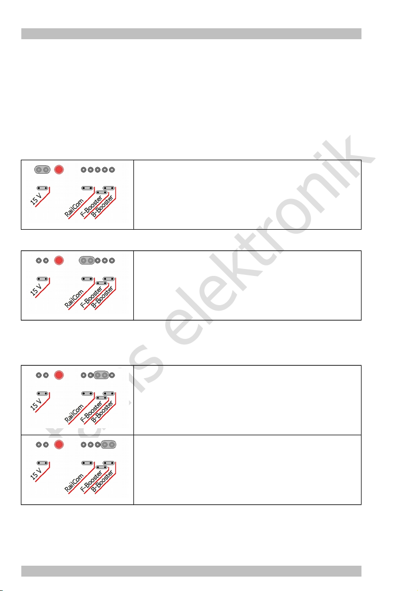
4.6.2. Configurating the integrated booster
On the rear side of your RedBox there are several pin headers, you can bypass with jumpers or
not to make settings:
15 V: setting the track voltage
RailCom: RailCom cutout on or off
F-Booster and B-Booster: Using the integrated booster as standard booster ("driving booster")
or as breaking booster
Setting the track voltage
Jumper set: 15 V (regulated)
Jumper not set: 19 V (regulated)
RailCom® cutout on / off
Jumper set: RailCom cutout switched on
Jumper not set: RailCom cutout switched off
Recommendation: If not using RailCom as feedback system,
you should switch off the RailCom cutout (jumper not set).
Choosing standard or breaking booster
You have to insert the jumper either ro F-Booster or B-Booster. When the jumper is not set, the
booster has no function, as a display the LED flashes.
Jumper set to F-Booster:
Use of the integrated booster as "standard booster" (driving
booster). At the booster output "normal" digital commands are
available to control vehicle and accessory decoders.
Jumper set to B-Booster:
Use of the integrated booster as "breaking booster". At the
booster output digital commands are available to control
vehicle and accessory decoders. For the vehicle decoders is
sent speed level "0" – regardless of the actually set value.
Seite 30
Page 31
tams elektronik
English RedBox
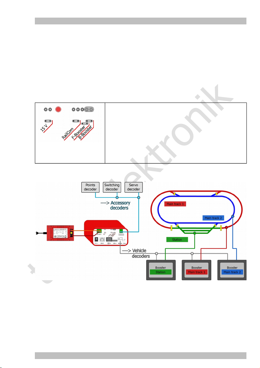
4.6.3. Driving and switching separately with one RedBox
You can configurate the integrated booster (for use as driving or breaking booster) that way,
sending digital commands to control accessory decoders will be suppressed. In doing so, you
prevent the transfer of vehicle commands being interrupted by sending commands for accessory
decoders. You need a PC (with program CV-Navi or control software) to set your RedBox to this
use.
Please note: The settings made for use as "standard booster" (driving booster) apply to all
external boosters as well. Basically, 4 different settings are possible. For most uses the following
setting makes sense:
Jumper set to B-Booster
+ no accessory commands to driving booster
This is the standard setting when sending commands for
vehicle and accessory decoders separately. The integrated
booster controls and supplies the accessory decoders, external
boosters are used to control and supply the vehicle decoders.
With this setting, it is possible to use the integrated booster as
a breaking booster as well.
Example of use: The integrated booster controls and supplies the accessory decoders. At the
interface for external boosters the accessory decoder commands are suppressed. The external
boosters tranfer driving commands for vehicle decoders only.
Seite 31
Page 32

tams elektronik
RedBox English
4.7. S88 feedback modules
You can connect a maximum of 52 s88 feedback modules or s88 compatible modules (with a
maximum of 832 contacts). It is possible to connect feedback modules with connections
according to the standard s88-N directly by using patch cables with RJ 45 connectors. In order
to connect previous modules with 6 pole pin connectors to your RedBox, you need an adapter
s88-A-SR or s88-A-BR. Please observe the manual for your s88 module!
à Section 11: Background information
Attention:
!
There are s88 feedback modules with RJ 45 connectors available which do not comply with the
standard s88-N. You should not connect these modules to your RedBox. When put into
operation, the RedBox and/or connected modules possibly are damaged.
Figure: Connection s88 modulen (max. 52 with 832 contacts)
Seite 32
Page 33

tams elektronik
English RedBox
4.8. Programming track
You can use the programming track
to read out and program vehicles decoders for the DCC format
to program the addresses of vehicles decoders for the mfx format and to read out their UID
Please have a look into the decoder´s manual to find out which programming modes can be
used and which parameters can be set.
Please not: It is not possible to program pure Motorola vehicle decoders on the programming
track, as this format does not provide this programming mode. Motorola decoders have to be
programmed on the main track according to the manufacturer´s specifications.
In order to make settings for the decoder on the programming track you need:
a piece of rails, which you connect to the programming track connection "Prog" of your
RedBox by means of the included connecting cable
an EasyControl device with software status 2.0 or higher (e.g.. LokControl, HandControl,
HandControl 2) or
a PC with software CV-Navi or a control software supporting the programming of decoders or
a mobile Android device (smartphone, tablet) with app "EasyControl Android", connected viy
a Raspberry Pi to the RedBox
Attention:
!
When integrating the programming track into your layout (e.g. as siding) you have to make
sure that both rails are disconnected from the rest of your layout.
If not, the connection for the programming track possibliy will be damaged!
Moreover, you would program every DCC decoder on your model railway.
4.9. Power supply for control devices
The power for your RedBox is supplied by an AC power pack (included in the scope of supply).
One AC power pack can handle the central unit and up to four additional control units. To use
more, a separate AC power pack can be connected to the BusControl.
Connect the power pack to the connection "12 V ~" on the rear side of the RedBox and the
power socket. As soon as the RedBox is ready for operation, the red LED on the front side lights
up.
Hint: The power pack supply the RedBox and up to four additional control units only, but not the
booster integrated in the versions "Booster" or "Booster-R". For supplying the integrated booster
(and rails) you need a transformer or a power supply unit.
→ Section 4.5.: Integrated booster
Seite 33
Page 34

tams elektronik
RedBox English
Seite 34
Page 35

tams elektronik
English RedBox
5. Adjusting parameters of the digital control
You can combine EasyControl with different types of devices. In the system parameters, you
have to define which types of devices (booster, decoders, etc.) you use, to ensure error-free
control of the devices.
Your RedBox does not allow to display, enter or edit the system parameters. For that purpose
you can use:
EasyControl devices (e.g. MasterControl, LokControl, HandControl, HandControl 2): The
devices must have a software version from 2.0. The manuals from version 07/2018 which are
available for free download on our homepage, give further information how to proceed.
PC (with software CV-Navi or control software with EasyControl support)
mobile Android smartphone or tablet with app "EasyControl Android" and Raspberry Pi
Setting duration of the signal pause in the Motorola format
These settings only apply to vehicle decoders in the Motorola format. It’s recommended to set
the signal pause to 1.5 ms. Only if problems with Motorola I decoders occur in operation mode,
should you change the setting to 4.025 ms.
Default value Possible settings
short
Configuring the boosters
The settings of both the booster type (Motorola or DCC) and the short circuit polarity apply to all
connected (external) boosters.
Default value Possible settings
DCC booster
Short circuit polarity
= 100 ms
short (= 1.5 ms)
long (= 4.025 ms)
DCC (conform) booster: short circuit polarity = "negative"
MM-(kompatible) booster: short circuit polarity = "positive"
Value range: AUS, 5, 10, 15, ... 1000 ms
Hint: The lower the set value, the faster the short circuit detection reacts and
booster outputs are switched off. Please note: A high value can cause "welding" in
case of a short circuit (especially in combination with a powerful booster).
Seite 35
Page 36

tams elektronik
RedBox English
Setting standard data format for vehicle decoders
This setting will be set as standard for the programming of all locomotive and function decoders.
Default value Possible settings
DCC format, 28 speed levels DCC format, 28 speed levels
Motorola format, 14 speed levels
You have to alter the settings in the locomotive data base if you want to control specific vehicle
decoders with a different format or number of speed levels. Make changes in the data base
with an EasyControl device: using the locomotive menu
with a PC: using the program "CV-Navi" or a control software
with a smartphone or tablet and a Raspberry Pi: using the app "EasyControl Android"
RailCom support
Default value Possible settings
++ Accessory
Booster options (for versions "Booster" and "Booster-R" only)
It is possible to suppress the output of accessory decoder commands individually for driving and
breaking booster, for none of them, or for both boosters. When using the integrated booster to
control accessory decoders ("switching") and the external booster(s) to control vehicle decoders
("driving"), you have to
off (0): The Railcom support is switched off.
Tailbits (1): There will be left space for the RailCom cutout
during data transfer.
+ IdNotify (2):The central unit sends regularly it´s
identification (in addition to Tailbits).
++ Accessory (3): The central unit sends regularly a point
command, to allow the points decoders sending feedback
signal (in addition to Tailbits and IdNotify).
put the jumper on "B-Booster"
adjust the booster option to "no accessory commands for driving booster"
Default value Possible settings
--- --no accessory commands for driving booster
no accessory commands for breaking booster
no accessory commands for driving and breaking booster
Hint: Normally, "no accessory commands for driving booster" is the only appropriate
setting.
Seite 36
Page 37

tams elektronik
English RedBox
Setting the number of s88 modules
Default value Possible settings
0 Value range: 0, 1, 2, 3….52
Setting switching time of solenoid accessory decoders
The setting applies to all solenoid accessory decoders.
Default value Possible settings
minimum switching time:
100 ms
maximum switching time:
5.0 s
Setting interface baud rate (version "V24" only)
Default value Possible settings
57600 Baud
Value range: 0, 50, 100, 150 ... 1000 ms
Hint: When setting a certain minimum switching time, you can switch points by
quickly tapping the function key, although the points need a longer switching time.
Value range: 0.1 , 0.2 , 0.3, 0.4 ... 25.5 s
Hint: By setting a certain maximum switching time, you can prevent damages at the
points caused by too long switching times.
Value range: 1200, 2400, 4800, 9600, 14400, 19200, 38400,
57600
Hints:
When using the serial interface, this value has to be set according to your PC
interface configuration.
The USB interface is 57600 and can’t be changed.
Seite 37
Page 38

tams elektronik
RedBox English
Seite 38
Page 39

tams elektronik
English RedBox
6. Operation
6.1. Switching on / off
Switching on your RedBox
After switching on the power supply for your RedBox, the connected booster(s) first have no
power, meaning that your track also has no power. The red LED in the "stop"-button is
illuminated.
Push the button "go" to switch on the boster(s). The green LED in the "go"-button is illuminated.
Switching off your RedBox
You can switch off all boosters by pressing "stop". If for instance two trains are about to crash,
you can stop the operation of your model railroad. Please note: The current speed levels and
function statuses are not discarded! As soon as you start operation again by pressing "go" all
active locomotives start moving as before.
Attention! Some locomotive decoders have additional power buffers, which can support a
locomotive when power is cut. Before operating such a decoder, please check how much
energy is stored and which of the locomotives is able to move without power, otherwise cutting
power to the booster(s) might not prevent a crash.
6.2. Plug and play
You can establish or interrupt connections of external devices or adapters to the EasyNet at any
time – even during ongoing operation (plug and play).
Seite 39
Page 40

tams elektronik
RedBox English
6.3. LED displays on the front side
The two buttons "go" and "stop" have an integrated red or rather red LED. The LEDs show the
operating mode of your RedBox.
red off
green off
red permanently on
green off
red off
green permanently on
red fast flashing A booster has reported a short circuit. As a consequent, the
green off
red slow flashing The update mode has been started for the RedBox.
green off
red
green
alternating
flashing
The RedBox has not been connected to the power supply.
The RedBox has been swithed on.
All boosters are switched off.
The RedBox has been swithed on. .
All boosters have been swithed on
RedBox has switched off the track power.
After having eliminated the short circuit, you have to push "go"
in order to restart operation.
In order to return to standard operation, you have to switch off
the RedBox (shortly interrupt the power supply).
Hint: Do not finish the update mode, after the software transfer has been started.
The update mode has been started for the external devices.
In order to return to standard operation, you have to switch off
the RedBox (shortly interrupt the power supply).
6.4. LED displays on the rear side (versions "Booster" and "Booster-R" only)
The LED on the rear side shows operating modes or issues encountered for the integrated
booster.
off RedBox and boosters are switched off.
permanently on RedBox and boosters are switched on.
slow flashing
(approx. once per second)
The booster does not receive signals from the central unit.
Please check,
if the central unit has been set to "stop".
if the jumper has been set to B-Booster or F-Booster. If not,
insert the jumper.
fast flashing A short circuit has occured at the track output, whereupon the
RedBox has switched off the track voltage.
After having eliminated the short circuit, you have to push "go"
in order to restart operation.
Seite 40
Page 41

tams elektronik
English RedBox
7. Update
Your RedBox and other EasyControl devices are state-of-the-art products, which are constantly
improved and adapted to occurring changes. To benefit from this development, you can update
the devcies to the newest software version.
Please note: All EasyControl devices used in one digital control system must have the same
software version! Otherwise malfunction of data transfer between the devices might occur.
You can download the most recent version of the software (firmware) for free from our
homepage (area "Download"). In order to perform the update, you need
a PC running Microsoft Windows or Linux and internet access
an USB cable (or when using the version "V24" a serial cable)
Software "CV-Navi", which you can download from our hoemage for free
If you cannot or do not want to perform the update yourself, you can send us your RedBox to
update it. In case you use further EasyControl devices together with your RedBox, you have to
send them in for update as well. The update is free of charge, we only charge the return
expenses according to our valid price list.
Software-Update for your RedBox
First, download the firmware (i.e. the software running the RedBox) from our homepage on your
PC. You find the firmware under:
www.tams-online.de/download/firmware
Then, switch off the RedBox. Simultaneously pressing "stop" and "go" switch the power back on,
while holding both keys. The red LED on the front side of the RedBox flashes and the green LED
is off.
Now please connect the MasterControl to your PC and execute the update application.
Please note: Always connect the MasterControl to your PC before executing the update
application. Otherwise your PC might have difficulties detecting the interface.
Follow the instructions of the update application.
Seite 41
Page 42

tams elektronik
RedBox English
8. Check list for troubleshooting
8.1. Errors occurring while starting up
After switching on track power, the locomotive responds to switching on / off its functions,
but not to turning a control device´s speed control knob.
Possible reason: The integrated booster (versions "Booster" and "Booster-R") has been
configurated as breaking booster and always sends a "0" as speed level. à Alter the
integrated booster´s configuration by putting the jumper on "F-Booster".
When switching on the booster by pressing "go", your RedBox switches off immediately, the
red LED in the "stop"-button flashes quickly.
Possible reason: The short circuit polarity settings of the booster(s) are wrong. à Change the
short circuit polarity settings.
Versions "Booster" and "Booster-R": After switching on the RedBox and pushing the "go"-
button the green LED in the "go-button" and the red LED of the integrated booster on the
rear side are illuminated. Nevertheless, the locomotives do not respond to turning a control
device´s speed control knob.
Possible reason: The power supply for the booster (transformer, switching power-supply)
have not been connected properly or not been switched on. à Check the booster´s power
supply.
8.2. Errors occurring while setting parameters
When programming a DCC decoder an error is displayed.
Possible reason: You’ve choosen a programming method not supported by the decoder.
à See the manual of the decoder for supported programming methods.
You cannot test all s88 modules, although their connection is ok.
Possible reason: The setting for the amount of s88 modules is wrong. à Change the setting
for the amount of s88 modules.
8.3. Errors occurring while operating
A locomotive does not respond to driving or function commands, although you entered the
right address.
Possible reason: The decoder is assigned a wrong format. à Change the data format.
A locomotive with DCC decoder immediately drives fast, although in speed level 1.
Possible reason: The decoder only supports 14 or 28 speed levels, but is assigned 128 ones.
à Change the amount of speed levels.
You can’t switch on / off lights on a locomotive with DCC decoder and / or when accelerating,
the lights flicker.
Possible reason: The speed level settings of both decoder and and in the locomotive data
base do not match. à Change the speed level settings of the decoder or in the data base.
Seite 42
Page 43

tams elektronik
English RedBox
When accelerating a locomotive with a Motorola decoder, only every second speed level
increases the locomotive’s speed.
Possible reason: The locomotive decoder was assigned speed level "27 a" or "27 b", but the
locomotive decoder only supports 14 speed levels. à Change the amount of speed levels in
the locomotive data base.
In operation mode, locomotives with Motorola I decoders are causing problems: They do not
respond to driving or function commands or have an odd driving behaviour.
Possible reason: The duration of the signal pause is set inaccurately. à Change the duration
of the signal pause.
The two locomotives in double traction move in opposite directions.
Possible reason: Before establishing a double traction, you did not set the driving direction for
both locomotives. à Repeat the creation of the double traction.
The points cannot be switched.
Possible reason: The point format is wrong. à Change the points format.
The RedBox does not respond to software commands of a connected PC.
The connection between MasterControl and PC is bad. à Check your cable. Also check, if the
right COM port is set in the software.
Possible reason (version "V24" only): The baud rate has been set faultily. à Alter the baud
rate.
8.4. Errors occurring during software update
After the software update, the RedBox won’t start.
Possible reason: You updated using the wrong software file, for instance an update for the
LokControl. à Update again.
While updating, the progress bar jumps back (often).
This is not an error. The update application checks continuously, if the data transferred is
correct. If this is not the case, it repeats the transfer.
Hotline
If problems with your device occur, our hotline is pleased to help you (mail address on the last
page).
Repairs
You can send in a defective device for repair (address on the last page). In case of guarantee
the repair is free of charge for you. With damages not covered by guarantee, the maximum fee
for the repair is 50 % of the current sales price according to our valid price list. We reserve the
right to reject the repairing of a module when the repair is impossible for technical or economic
reasons.
Please do not send in devices for repair charged to us. In case of warranty we will reimburse
the forwarding expenses up to the flat rate we charge according to our valid price list for the
delivery of the product. With repairs not covered by guarantee you have to bear the expenses
for sending back and forth.
Seite 43
Page 44

tams elektronik
RedBox English
9. Technical Specifications
9.1. RedBox
Motorola-I and –II
Data formats
Power supply 12 volts AC
Power consumption (without consumer) approx. 200 mA
Interfaces for the connection of
external control devices
PC interfaces
(galvanically isolated)
Other interfaces
Maximum amount of s88 modules
Vehicle decoder addresses
Speed levels
Functions
Accessory decoder addresses
DCC (corresponding to NMRA-and RCN-standard)
m3 (for driving mfx decoders)
EasyNet (RJ 45)
XpressNet (RJ 12)
Versions "Basic", "Basic-R", "Booster", "Booster-R":
USB-1 type Mini-B with Tams identifier
USB-2 type B with SiLabs identifier
Version "V24":
one serial interface (baud rate adjustable)
one USB interface with Tams identifier
Booster (optionally compatible with Märklin or DCC
conform)
DCC programming track
s88 feedback module (corresponding to standard s88-N)
Power supply
52 s88 or s88 compatible modules
(832 contacts)
Motorola: 255 (1 – 255)
DCC: 10239 (1 – 10239)
m3: 16384
Motorola: 14 or 27 (a or b)
DCC: 14, 28 or 128
m3: 128
Motorola: function, f1 to f4
DCC: f0 to f28 resp. f32768
m3: f0, f1 to f15
Motorola: 1020 (1 – 1020)
DCC: 2040 (1 – 2040)
m3: ---
Seite 44
Page 45

tams elektronik
English RedBox
Protection IP 00
Ambient temperature while operating 0 - + 60 °C
Ambient temperature in storage - 10 to + 80 °C
Comparative humidity allowed max. 85 %
Dimensions (approx.) 95 x 135 x 45 mm
Version "Basic" 160 g
Version "Basic-R" 172 g
Weight (approx.)
9.2. Integrated Booster (Versions "Booster" and "Booster-R")
Version "Booster" 215 g
Version "Booster-R" 217 g
Version "V24" 170 g
Supply voltage
Output voltage 15 or 19 volts digital voltage (regulated)
Power consumption max. 48 watt
Maximum output current 2,5 A
Data formats
Feedback log RailCom (RailCom cutout can be switched off)
Output signal symmetrical
16 - 18 volts AC voltage or
17 – 22 volts DC voltage
DCC, Motorola
mfx (vehicle decoder commands only)
Seite 45
Page 46

tams elektronik
RedBox English
10. Background information
10.1. Motorola-Format
Märklin** originally introduced the Motorola format, using Chips from Motorola, hence the name.
First, only 80 addresses could be used, later this was extended to 255.
Data transfer in the Motorola format
Data is transferred in so called packets, which are sent with pauses in between. This kind of
data transfer results in DC power on the track. Hence, locomotives without decoder start moving
as soon as they are put on the track.
The previously developed Motorola I format relies on sending packets on two different
frequencies: One data packet contains the address information, the 14 speed level data, and the
status of one function and is continuously sent. A theoretically possible 15th speed level is used
to switch driving directions. The information about the state of additional functions is sent in the
second packet. This is only sent, if the status changes.
The later developed Motorola II format relies on sending one packet continuously: This packet
contains the address and the speed levels as well as additional information about the status of
the four functions and the absolute driving direction. The Motorola II format allows only 14
speed levels as well. In the meantime, decoders have become available, which support 27 speed
levels by adding additional “half levels” in between the existing speed levels.
Compatibility of both Motorola formats
Regardless which of the two Motorola format the decoder receives, it can change the speed
level, the driving direction and the function “light” correctly. To be able to use the four additional
functions, it must be controlled using the appropriate format.
Driving solenoid accessory decoders for the Motorola format
The information to switch solenoid accessory decoders (points und switching decoders) is sent in
the same second data packet in the Motorola I format as the information of the four additional
functions. In the Motorola II format, this second packet only contains information to drive
solenoid accessory decoders. This data packet is only sent, when the status of solenoid
accessory decoders changes.
With 80 addresses this adds up to 80 x 4 = 320, with 255 to 255 x 4 = 1020 addresses.
When calling address from a control unit, it must distinguish between locomotive and solenoid
accessory decoders, in order to control both. It depends on the control unit how this is done.
Seite 46
Page 47

tams elektronik
English RedBox
10.2. DCC-Format
The DCC format was developed by LENZ** and later declared as standard by the NMRA
(National Model Railroad Association). Meanwhile the RailCommunity (Association of
Manufacturers of Model Railcroad Products) maintains and advances this standard.
Data transfer in the DCC format
In the DCC format, data is transferred continuously and thus there is no DC power on the track.
Hence, different to Motorola formats, locomotives without decoders do not automatically start
moving when put on the track. It is possible to control one decoderless locomotive from the
central unit in DCC layouts, because the analog driving signals are laid over the digital signals.
Nonetheless, this feature is not recommended, as it tends to damage the engine electrics. This is
the reason why it is not supported in EasyControl.
Possibilities of the DCC format
The DCC format features up to 10239 addresses, up to 28 (or 32768) functions and up to 128
speed levels as well as an absolute driving direction. How may addresses, functions and speed
levels can actually be used depends on component limits such as the limits of decoders or the
central unit.
CV programming
Today’s CV programming allows you to set a decoders properties by setting the so-called
configuration variables (CV variables). The meaning of each variable is clearly defined by the
NMRA. Each variable has 8 bits and can contain the values of 0 to 255. To be able to use
extended addresses, one address uses two CV variables. The values can be transferred bitwise
or bytewise. Bitwise transfer only makes sense if each bit has its’ own property (e.g. CV# 29). In
the table in ssection 10.2. you can find the most commonly used CV variables and their possible
values.
Page programming and register programming
Before CV programming, there was register programming and page programming.
The possibilities to set the decoder properties are limited when page programming is used.
There are only 8 registers to program (primary address, Vstart, acceleration rate, deceleration
rate, configuration data, manufacturer version No., manufacturer ID). The possible values of the
register variables are analog to those of the CV variables.
Page programming offers the same possibilities as CV programming. The properties of the
decoder are set in register variables. 4 registers make one page. The pages are adjacent
(register 1 to 4 on Page 0, register 5 to 8 on page 1, and so on) so a register can be accessed
directly while programming.
Seite 47
Page 48

tams elektronik
RedBox English
Configuration variables for the DCC format (exert)
CV# CV name Value
(Default value)
1 Primary address 0 ... 127
(3)
2 Vstart 0 ... 255
(-)
3 Acceleration rate 0 ... 255
(-)
4 Deceleration rate 0 ... 255
(-)
5 Vhigh 0 ... 255
(0)
6 Vmid 1 ... 255
(1)
7 Manufacturer
version No.
8 Manufacturer ID e.g. 62 In this case: Tams Elektronik GmbH
9 Total PWM period 0 ... 255
17 + 18Extended address 1 ... 10239
19 Consist address 0 ... 127
29 Configuration data#10 ... 255
33 – 46Output Loc. FL(f),
FL(r), F1-F12
1 ... 255 This is the version number of the decoder’s internal
(0)
(-)
(-)
(-)
0 ... 255
(-)
Explanations
The primary address contains a value between 1 and
127. Is the CV#1 equal to 0, the decoder switches to
analog mode.
Defines the current powering the engine at minimum
speed.
Defines the duration of the pause while switching up
to the next higher speed level.
Defines the duration of the pause while switching
down to the next lower speed level.
Defines the current powering the engine at maximum
speed.
Defines the current powering the engine at moderate
speed.
software.
The current powering the electric motors is facilitated
by switching on / off the power. The interval
between those power peeks is called PMW period. By
altering the PMW period, the individual running
characteristics of an electric motor are changed.
Defines the address between 1 and 10239, if the
decoder is set to extended addresses.
Defines the alternate (second) address of the
decoder.
Defines main properties of the decoder: Driving
direction, amount of speed steps, switching to analog
operation, additional feedback while in programming
mode, choice of the speed table, primary addresses
or extended addresses.
Contains a matrix indication of which function inputs
control which Digital Decoder outputs.
Seite 48
Page 49

tams elektronik
English RedBox
CV# CV name Value
(Default value)
49 – 64Manufacturer
Unique
67 – 94Speed Table
(only in 28 speed
steps mode)
0 ... 255
(-)
0 ... 255
(-)
Explanations
Reserved for manufacturer unique CV’s.
A speed table consisting of 28 values for forward
speeds forming a smooth power curve, whereas each
speed step is assigned a specific engine power value.
A value of "0" is defined as no power, a value of
"255" as maximum power.
10.3. m3
We have developped this protocol for our digital system EasyControl in order to drive mfx
vehicle decoders. It is possible to program vehicles with mfx decoders on a programming track
connected to the RedBox or the MasterControl. m3 does not allow to read feedback messages
sent via mfx.
10.4. s88
In PC controlled layouts remote indication via the s88 bus is very common. Many digital central
units have a (usually 6 pole) connection for a s88 cable. Remote indication via the s88 bus is
customary in a.c. as well as in d.c. layouts – independent of the digital format in use.
Most feedback modules allow to connect up to 16 inputs, whose state (open or connected to
earth) is reported to the receiver (interface or central unit). Several feedback modules can be
connected in series, the maximum number depends on the receiver (e.g. 52 with MasterControl
or RedBox).
s88-N
The standard s88-N regulates the assignment of commercial Ethernet patch-cables for use in
s88 feedback systems. Unlike the 6-conductor connecting cables frequently used in the past, the
patch-cables used in computer networks are screened against outside electric signals. Thus
using patch-cables reduces the liability to interference considerably, even with long lines. All
modules corresponding to this standard are compatible to each other.
Seite 49
Page 50

tams elektronik
RedBox English
10.5. RailCom
RailCom is an extension of the DCC protocol and defines all details of importance for reporting
back data in DCC controlled digital layouts. The basic idea is that RailCom compatible decoders
are not only used as recipients of digital commands but also report back data via the rails to the
RailCom detectors.
In order to make room for reporting back data, special RailCom boosters cut short gaps into the
continuous DCC data stream from the central unit to the decoders. These RailCom cutouts are
used to send data from the decoders to the detectors.
Using RailCom allows you e.g. to send commands to read out CVs from the central unit to the
decoders and to display the CVs´ values at the RailCom detectors.
Seite 50
Page 51

tams elektronik
English RedBox
10.6. Boosters
Boosters amplify the digital signals send from the central unit and supply a connected track with
power. You have to connect at least one external booster to the MasterControl, as there is no
booster integrated. The actual number of boosters needed depends on the power consumption
of your model railway.
Measuring the power consumption
a locomotive: Gauge N: 600 mA / Gauge H0: 800 mA / > Gauge 0: 1 A
a wagon light: 50 - 200 mA
another consumer (such as a sound module): 100 - 300 mA
reserve for points: 10% of the calculated sum of power consumption
Booster types
Märklin**-compatible and DCC-compatible boosters are switched on / off in different ways.
Märklin**-compatible boosters are switched on using their own signal switched with an extra pin
on the booster port. DCC boosters are switched on as soon as a data signal is recognized. The
booster ports of the MasterControl can be configured to work with both types.
Balanced boosters keep the power in a specific track section constant. Contrary to that, sections
with non-balanced boosters might suffer from increasing and decreasing power, causing
changes in locomotive speeds and the lightings´brightness.
Hint 1
Split your model railway layout in several track sections. Each section should run a maximum of
3 to 5 locomotives. Make sure that section borders are not crossed that often.
Hint 2
Only use boosters of one type and made by one manufacturer to avoid problems when crossing
the interruption between two track sections such as:
Problems with data transfer to the decoders.
Current leakage that make locomotives move by themselves.
Short circuits when crossing sections.
Seite 51
Page 52

tams elektronik
RedBox English
11. The asterisks **
This manual mentions the following companies:
ESU electronic solutions ulm GmbH & Co. KG
Edisonallee 29
DE-89231 Neu-Ulm
LENZ** Elektronik GmbH
Vogelsang 14
DE-35398 Gießen
MASSOTH** Elektronik GmbH
Frankensteiner Str. 28
DE-64342 Seeheim
Gebr. MÄRKLIN** & Cie. GmbH
Stuttgarter Straße 55-57
DE-73033 Göppingen
ROCO**
Modelleisenbahn München GmbH
Kronstadter Str. 4
DE-81677 München
Seite 52
Page 53

tams elektronik
English RedBox
12. Guarantee bond
For this product we issue voluntarily a guarantee of 2 years from the date of purchase by the
first customer, but in maximum 3 years after the end of series production. The first customer is
the consumer first purchasing the product from us, a dealer or another natural or juristic person
reselling or mounting the product on the basis of self-employment. The guarantee exists
supplementary to the legal warranty of merchantability due to the consumer by the seller.
The warranty includes the free correction of faults which can be proved to be due to material
failure or factory flaw. With kits we guarantee the completeness and quality of the components
as well as the function of the parts according to the parameters in not mounted state. We
guarantee the adherence to the technical specifications when the kit has been assembled and
the ready-built circuit connected according to the manual and when start and mode of
operation follow the instructions.
We retain the right to repair, make improvements, to deliver spares or to return the purchase
price. Other claims are excluded. Claims for secondary damages or product liability consist only
according to legal requirements.
Condition for this guarantee to be valid, is the adherence to the manual. In addition, the
guarantee claim is excluded in the following cases:
if arbitrary changes in the circuit are made,
if repair attempts have failed with a ready-built module or device,
if damaged by other persons,
if damaged by faulty operation or by careless use or abuse.
Seite 53
Page 54

tams elektronik
RedBox English
13. EU declaration of conformity
This product conforms with the EC-directives mentioned below and is therefore CE
certified.
2004/108/EG on electromagnetic. Underlying standards: EN 55014-1 and EN 61000-6-3.
To guarantee the electromagnetic tolerance in operation you must take the following
precautions:
Connect the transformer only to an approved mains socket installed by an authorised
electrician.
Make no changes to the original parts and accurately follow the instructions, connection
diagrams and PCB layout included with this manual.
Use only original spare parts for repairs.
2011/65/EG on the restriction of the use of certain hazardous substances in electrical and
electronic equipment (ROHS). Underlying standard: EN 50581.
14. Declarations conforming to the WEEE directive
This product conforms with the EC-directive 2012/19/EG on waste electrical and
electronic equipment (WEEE).
Don´t dispose of this product in the house refuse, bring it to the next recycling bay.
Seite 54
Page 55

tams elektronik
English RedBox
Seite 55
Page 56

tams elektronik
n
n
n
n
n
n
n
n
Information and tips:
http://www.tams-online.de
Warranty and service:
Tams Elektronik GmbH
Fuhrberger Straße 4
DE-30625 Hannover
fon: +49 (0)511 / 55 60 60
fax: +49 (0)511 / 55 61 61
e-mail: modellbahn@tams-online.de
n
n
n
n
n
n
n
n
n
n
n
 Loading...