

Page 1
tams elektronik
Manual
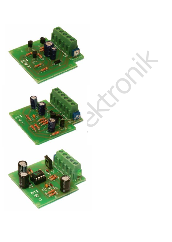
Minitimer MT-1
"Time Switch"
Item 51-01015 | 51-01016 | 51-01017
Minitimer MT-2
"Delayed switching"
Item 51-01025 | 51-01026 | 51-01027
Minitimer MT-3
"Pulse delay"
Item 51-01035 | 51-01036 | 51-01037
tams elektronik
n n n
Page 2

tams elektronik
English MT-1 | MT-2 | MT-3
Contents
1. Getting started............................................................................3
2. Safety instructions.......................................................................5
3. Safe and correct soldering...........................................................7
4. Operation overview.....................................................................9
5. Technical specifications..............................................................12
6. Assembling the kit.....................................................................13
7. Performing a functional test.......................................................22
8. Connecting the MT-1.................................................................23
9. Connecting the MT-2.................................................................26
10. Connecting the MT-3.................................................................29
11. Check list for troubleshooting.....................................................32
12. Guarantee bond........................................................................34
13. EU Declaration of Conformity.....................................................35
14. Declarations concerning the WEEE directive................................35
Version 2.5 08/2021
© Tams Elektronik GmbH
All rights reserved, in particular the right of reproduction, distribution
and translation. Copies, reproductions and alterations in any form
require the written permission of Tams Elektronik GmbH. We reserve
the right to make technical changes.
Printing the manual
The formatting is optimised for double-sided printing. The standard
page size is DIN A6. If you prefer a larger display, printing on DIN A5 is
recommended.
Seite 2
Page 3
tams elektronik
!
MT-1 | MT-2 | MT-3 English
1. Getting started
How to use this manual
This manual gives step-by-step instructions for safe and correct
assembly of the kit and fitting and connecting of the ready-built
module, and operation. Before you start, we advise you to read the
whole manual, particularly the chapter on safety instructions and the
checklist for trouble shooting. You will then know where to take care
and how to prevent mistakes which take a lot of effort to correct.
Keep this manual safely so that you can solve problems in the future. If
you pass the kit or the ready-built module on to another person, please
pass on the manual with it.
Intended use
The minitimers MT-1, MT-2 and MT-3 are designed to be operated
according to the instructions in this manual in model building, especially
with model railways. Any other use is inappropriate and invalidates any
guarantees.
The minitimers MT-1, MT-2 and MT-3 should not be assembled or
mounted by children under the age of 14.
Reading, understanding and following the instructions in this manual
are mandatory for the user.
Caution:
The minitimer MT-3 contains integrated circuits. These are very
sensitive to static electricity. Do not touch components without first
discharging yourself. Touching a radiator or other grounded metal part
will discharge you.
Seite 3
Page 4

tams elektronik
English MT-1 | MT-2 | MT-3
Checking the package contents
Please make sure that your package contains:
one kit, containing the components listed in the parts list and one
PCB:
MT-1 page 17
MT-2 page 18
MT-3 page 19
or one ready-built module
or one ready-built module in a housing (complete unit).
Required materials
To assemble the kit you will need
a soldering iron with temperature control and a thin tip and a deposit
stand or a controlled soldering station
a scraper, rag or sponge
a heat-resistant pad
a small pair of side cutters and wire strippers
tweezers and flat-nose pliers if necessary
electronic solder (preferably 0.5 to 0.8 mm diameter)
For testing the module you need an electric light bulb.
In order to connect the module you need wire. Recommended
diameters: > 0,14 mm² for all connections.
In order to activate the circuit you need :
MT-1
push-button
e.g. push-button item no. 85-5212x, x=1,2,3,6,7
MT-2
switch
e.g. toggle switch 1xUm item no. 84-51510
MT-3
push-button
e.g. push-button item no. 85-5212x, x=1,2,3,6,7
Seite 4
Page 5

tams elektronik
MT-1 | MT-2 | MT-3 English
In order to connect the devices you possibly need a relay (see sections
8, 9 and 10):
MT-1 relay 12 V e.g. relay 1xUm 12 V, item no. 84-61010
MT-2 relay 5 V e.g. relay 2xUm 5 V, item no. 84-61020 and
protective diode 1N4148, item no.83-11100
MT-3 relay 12 V e.g. relay 1xUm 12 V, Art.-Nr. 84-61010
2. Safety instructions
Mechanical hazards
Cut wires can have sharp ends and can cause serious injuries. Watch
out for sharp edges when you pick up the PCB.
Visibly damaged parts can cause unpredictable danger. Do not use
damaged parts: recycle and replace them with new ones.
Electrical hazards
Touching powered, live components,
touching conducting components which are live due to malfunction,
short circuits and connecting the circuit to another voltage than
specified,
impermissibly high humidity and condensation build up
can cause serious injury due to electrical shock. Take the following
precautions to prevent this danger:
Never perform wiring on a powered module.
Assembling and mounting the kit should only be done in closed,
clean, dry rooms. Beware of humidity.
Only use low power for this module as described in this manual and
only use certified transformers.
Connect transformers and soldering irons only in approved mains
sockets installed by an authorised electrician.
Seite 5
Page 6

tams elektronik
English MT-1 | MT-2 | MT-3
Observe cable diameter requirements.
After condensation build up, allow a minimum of 2 hours for
dispersion.
Use only original spare parts if you have to repair the kit or the
ready-built module.
Fire risk
Touching flammable material with a hot soldering iron can cause fire,
which can result in injury or death through burns or suffocation.
Connect your soldering iron or soldering station only when actually
needed. Always keep the soldering iron away from inflammable
materials. Use a suitable soldering iron stand. Never leave a hot
soldering iron or station unattended.
Thermal danger
A hot soldering iron or liquid solder accidentally touching your skin can
cause skin burns. As a precaution:
use a heat-resistant mat during soldering,
always put the hot soldering iron in the soldering iron stand,
point the soldering iron tip carefully when soldering, and
remove liquid solder with a thick wet rag or wet sponge from the
soldering tip.
Dangerous environments
A working area that is too small or cramped is unsuitable and can cause
accidents, fires and injury. Prevent this by working in a clean, dry room
with enough freedom of movement.
Other dangers
Children can cause any of the accidents mentioned above because they
are inattentive and not responsible enough. Children under the age of
14 should not be allowed to work with this kit or the ready-built
module.
Seite 6
Page 7
tams elektronik
!
!
MT-1 | MT-2 | MT-3 English
Caution:
Little children can swallow small components with sharp edges, with
fatal results! Do not allow components to reach small children.
In schools, training centres, clubs and workshops, assembly must be
supervised by qualified personnel.
In industrial institutions, health and safety regulations applying to
electronic work must be adhered to.
3. Safe and correct soldering
Caution:
Incorrect soldering can coffe dangers through fires and heat. Avoid
these dangers by reading and following the directions given in the
chapter Safety instructions.
Use a soldering iron with temperature control, which you set to
approx. 300 °C.
Only use electronic solder with a flux.
Never use soldering water or soldering grease when soldering
electronic circuits. These contain an acid that destroys components
and conductor paths.
Insert the connecting wires of the components as far as possible
through the holes of the board without using force. The body of the
component should be close above the board.
Make sure that the polarity of the components is correct before
soldering them.
Solder quickly: soldering for too long can coffe pads or tracks to
become detached or even destroy components.
Hold the soldering tip on the soldering point in such a way that it
touches the component wire and the pad at the same time. Add (not
Seite 7
Page 8

tams elektronik
English MT-1 | MT-2 | MT-3
too much) solder simultaneously. As soon as the solder begins to
flow, remove it from the soldering point. Then wait a moment for the
solder to flow well before removing the soldering iron from the
soldering joint.
Do not move the component you have just soldered for about 5
seconds.
A clean, non-oxidised (scale-free) soldering tip is essential for a
perfect soldering joint and good soldering. Therefore, before each
soldering, wipe off excess solder and dirt with a damp sponge, a
thick damp cloth or a silicone wiper.
After soldering, cut off the connecting wires directly above the
soldering point with a side cutter.
After assembly, always check each circuit again to ensure that all
components are correctly inserted and polarised. Also check that no
connections or tracks have been accidentally bridged with tin. This
can lead not only to malfunction, but also to the destruction of
expensive components. You can re-liquefy excess solder with the
clean hot soldering tip. The solder then flows from the board to the
soldering tip.
Seite 8
Page 9

tams elektronik
MT-1 | MT-2 | MT-3 English
4. Operation overview
Minitimer MT-1 "Time Switch"
The minitimer MT-1 is designed for controlling operations in model
railways which are supposed to last for 1 to 100 seconds. The desired
switching time is set via a trimming potentiometer.
Examples of use: Automatic opening of the gate at a level crossing after
a certain time, automatic stop of trains at the platform for a certain
time.
The circuit is triggered by a positive switching pulse at the module´s
input, for instance via a key switch or a reed contact. Then the output
is grounded for the preset time.
Devices with a current up to 100 mA intended to be switched on can be
connected directly to the minitimer´s output. Devices with a higher
current or devices intended to be switched off, can be controlled via a
relay. It is also possible to switch over between two devices by
connecting a relay.
Minitimer MT-2 "Delayed switching"
The minitimer MT-2 switches on or off operations in model railways
with a time delay between 0 and 25 seconds. The desired time delay is
set via a trimming potentiometer.
Examples of use: Delay of a locomotive´s start after changing the
signal to "go" (= the engine driver´s reaction time).
The circuit is triggered by grounding the module´s input, e.g. via a
switch. The module´s output is grounded after the preset delay time
has elapsed, the connected device consequently is not switched on until
the delay time is over.
If the earth connection at the module´s input is interrupted, the
connected device is switched off with a time delay of approx. 1 second.
If the time passing between making and interrupting the earth
Seite 9
Page 10

tams elektronik
English MT-1 | MT-2 | MT-3
connection at the module´s input is shorter than the preset delay time,
the connected device stays off.
Devices with a current up to 100 mA intended to be switched on after a
certain delay time can be connected directly to the minitimer´s output.
Devices with a higher current or devices supposed to be switched off
can be controlled via a relay.
Minitimer MT-3 "Pulse delay"
The minitimer MT-3 transfers voltage changes with a time delay
between 0 and 60 seconds to a connected device on a model railway.
The desired time delay is set via a trimming potentiometer.
Examples of use: Delayed triggering of solenoid operated devices
(signals, points, bistable relay), delayed power cut-off in a rail section
after crossing a reed contact in order to release the contact.
The circuit is controlled by an IC saving the voltage changes´sequence
at the module´s input and transferring them with the preset time delay
between 0 and 60 seconds to the output. The time period between two
voltage changes at the module´s input can be as long as you like. The
IC can save up to seven voltage changes within the preset delay time.
With more than seven voltage changes within the preset delay time the
first saved voltage change will be overwritten.
Devices with a current up to 1.000 mA can be connected directly to the
minitimer´s output. Devices with a higher current or devices intended
to be switched invertedly can be controlled via a relay.
Seite 10
Page 11
tams elektronik
MT-1 | MT-2 | MT-3 English
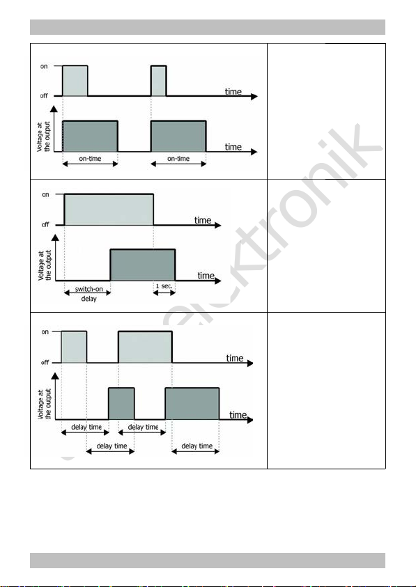
Minitimer MT-1
A = bridging the
switching inputs
B = voltage at the output
U = voltage
t = time
Δt = on-time
Minitimer MT-2
A = voltage at the input
B = voltage at the output
U = voltage
t = time
Δt = switch-on delay
Minitimer MT-3
A = voltage at the input
B = voltage at the output
U = voltage
t = time
Δt = delay time
Seite 11
Page 12

tams elektronik
English MT-1 | MT-2 | MT-3
5. Technical specifications
Supply voltage 12-18 Volt a.c. or d.c. voltage
Current consumption (without
connected devices) approx.
5 mA
Max. current at the output MT-1: 100 mA
MT-2: 100 mA
MT-3: 1.000 mA
Max. switching time (+ 20 %) MT-1: 100 seconds
MT-2: 25 seconds
MT-3: 60 seconds
Protected to
IP 00
Ambient temperature in use 0 ... +60 °C
Ambient temperature in storage -10 ... +80 °C
Comparative humidity allowed max. 85 %
Dimensions
of the PCB (approx.)
including housing (approx.)
48 x 52 mm
70 x 60 x 25 mm
Weight (approx.) assembled
board
including
housing
MT-1 17 g 34 g
MT-2 16 g 33 g
MT-3 19 g 36 g
Seite 12
Page 13

tams elektronik
MT-1 | MT-2 | MT-3 English
6. Assembling the kit
You can skip this part if you have purchased a ready-built module or device.
Preparation
Put the sorted components in front of you on your workbench.
The separate electronic components have the following special features
you should take into account in assembling:
Resistors
Resistors reduce current.
The value of resistors for smaller power ratings is indicated
through colour rings. Every colour stands for another
figure.
Carbon film resistors have 4 colour rings. The 4th ring
(given in brackets here) indicates the tolerance of the
resistor (gold = 5 %).
Value: Colour rings:
1 k brown - black - red (gold)
3,3 k orange - orange - red (gold)
4,7 k yellow - violet - red (gold)
5,6 k green - blue - red (gold)
10 k brown - black - orange (gold)
47 k yellow - violet - orange (gold)
330 k orange - orange - yellow (gold)
Seite 13
Page 14

tams elektronik
English MT-1 | MT-2 | MT-3
Trimm-potentiometers
Trimm-potentiometers (abrv. "trimm-pots") are resistors
which allow the value of resistance to be varied and that
way to be adapted to the particular demands. In the
middle they have a small slot into which a small
screwdriver can be put in order to vary the value of
resistance. The maximum value is printed on the housing.
Depending on the mounting situation trimmpots with a lying or a
standing package are used.
Ceramic capacitors
Among other things ceramic capacitors are used for
filtering interference voltages or as frequency determining
parts. Ceramic capacitors are not polarized.
Normally they are marked with a three-digit number which
indicates the value coded. The number 104 corresponds to
the value 100 nF.
Electrolytic capacitors
Electrolytic capacitors are often used to store energy. In
contrast to ceramic capacitors they are polarized. The
value is given on the package.
Electrolytic capacitors are available with different voltage
sustaining capabilities. Using an electrolytic capacitor with
a voltage sustaining capability higher than required is
always possible.
Seite 14
Page 15

tams elektronik
MT-1 | MT-2 | MT-3 English
Diodes and Zener diodes
Diodes allow the current to pass through in one direction
only (forward direction), simultaneously the voltage is
reduced by 0,3 to 0,8 V. Exceeding of the limit voltage
always will destroy the diode, and allow current to flow in
the reverse direction.
Zener diodes are used for limiting voltages. In contrast to "normal"
diodes they are not destroyed when the limit voltage is exceeded.
The diode type is printed on the package.
Light emitting diodes (LEDs)
When operated in the forward direction the LEDs light.
They are available in several different versions (differing in
colour, size, form, luminosity, maximum current, voltage
limits).
Light emitting diodes should always be connected via a
series resistor which limits the current and prevents failure.
Transistors
Transistors are current amplifiers which convert low signals
into stronger ones. There are several types in different
package forms available. The type designation is printed
on the component.
Transistors for a low power rating (e.g. BC types) have a
package in form of a half zylinder (SOT-package).
Transistors for a high power rating (e.g. BD types) have a
flat package (TO-package), which is in use in different
versions and sizes.
The three pins of bipolar transistors (e.g. BC and BD
types) are called basis, emitter and collector (abbreviated
with the letters B, E, C in the circuit diagram).
Seite 15
Page 16

tams elektronik
English MT-1 | MT-2 | MT-3
Integrated circuits (ICs)
Depending on the type, ICs fulfil various tasks. The most
common housing form is the so-called "DIL"-housing, from
which 4, 6, 8, 14, 16, 18 or more "legs" (pins) are
arranged along the long sides.
ICs are sensitive to damage during soldering (heat,
electrostatic charging). For that reason in the place of the
ICs IC sockets are soldered in, in which the ICs are
inserted later.
Microcontrollers
Microcontrollers are ICs, which are individually programmed for the
particular application. The programmed controllers are only available
from the manufacturer of the circuit belonging to it.
Terminal strips
Terminal strips are solder-in screw-type terminals. They provide a
solder-free and safe connection of the cables to the circuit, which can
still be separated any time.
Seite 16
Page 17

tams elektronik
MT-1 | MT-2 | MT-3 English
MT-1: PCB layout and parts list
Resistors R1, R2, R3, R4 3,3 k
R5, R6, R7 1 k
Trim pots R8 500 k
Capacitors C4 100 nF
Electrolytic capacitors C1, C2, C3 220 µF / 25 V
Diodes D2, D3 1N400x, x=2...7
Zener diodes D1 5V1
Transistors Q1, Q2, Q3 BC547B
Terminal strips X1 ... X6
Seite 17
Page 18

tams elektronik
English MT-1 | MT-2 | MT-3
MT-2: PCB layout and parts list
Resistors R1 10 k
R2 5,6 k
R3 1 k
R4, R5, R6 47 k
Trim pots R7 500 k
Diodes D1 1N400x, x=2...7
Electrolytic capacitors C1 100 µF/25 V
C2 470 µF/16 V
Transistors Q1, Q2 BC547B
Q3 BC557
Terminal strips X1, X2
Seite 18
Page 19

tams elektronik
MT-1 | MT-2 | MT-3 English
MT-3: PCB layout and parts list
Resistors R1, R2, R4, R6, R8 1 k
R3 4,7 k
R5 330 k
Trim pots R7 500 k
Diodes D1, D3, D4 1N4148
D5 1N400x, x=2...7
Zener diodes D2 ZD 5V1
LEDs D6
Capacitors C4 100 nF
Electrolytic capacitors C1, C2, C3 220 µF/25 V
Transistors T1 BD679
Micro-Controller / IC sockets IC1 PIC 12F508A
Terminal strips X1, X2
Seite 19
Page 20

tams elektronik
!
English MT-1 | MT-2 | MT-3
Assembly
Proceed according to the order given in the list below. First solder the
components on the solder side of the PCB and then cut the excess
wires with the side cutter. Follow the instructions on soldering in
section 3.
Caution:
Several components have to be mounted according to their polarity. When
soldering these components the wrong way round, they can be damaged
when you connect the power. In the worst case the whole circuit can be
damaged. At the best, a wrongly connected part will not function.
1. Resistors Mounting orientation of no importance.
2. Diodes, Zener
diodes
Observe the polarity!
The negative end of the diodes is marked with
a ring. This is shown in the PCB layout.
3. Ceramic
Capacitors
(MT-1 and MT-3 only)
Mounting orientation of no importance.
4. Transistors Observe the polarity!
The cross section of transistors for a low power
rating in SOT-packages is shown in the PCB
layout.
With transistors for a high power rating in TO
packages (e.g. BD types) the unlabelled back
side is marked in the PCB layout by a thick
line.
5. IC sockets
(MT-3 only)
Mount the sockets that way, the markings on
the sockets show in the same direction as the
markings on the PCB board.
Seite 20
Page 21

tams elektronik
MT-1 | MT-2 | MT-3 English
6. Electrolytic
capacitors
Observe the polarity! One of the two leads (the
shorter one) is marked with a minus sign.
7.
Terminal strips
Put together the terminal strips before
mounting them.
8. Trimmpotentiometers
The mounting orientation is preset by the
layout of the three pins.
9. Light emitting
diodes (LEDs)
(MT-3 only)
Observe the polarity!
With wired LEDs the longer lead is always the
anode (positive pole).
10. ICs in DILhousing
Insert the ICs into the soldered socket.
Do not touch the ICs without first discharging
yourself by touching a radiator or other
grounded metal parts.
Do not bend the "legs" when inserting them
into the sockets. Check that the markings on
the PCB, the socket and the IC show to the
same direction.
Performing a visual check
Perform a visual check after the assembly of the module and remove
faults if necessary:
Remove all loose parts, wire ends or drops of solder from the PCB.
Remove all sharp wire ends.
Check that solder contacts which are close to each other are not
unintentionally connected to each other. Risk of short circuit!
Check that all components are polarised correctly.
When you have remedied all faults, go on to the next part.
Seite 21
Page 22

tams elektronik
!
English MT-1 | MT-2 | MT-3
7. Performing a functional test
With all minitimers it is recommended to check function and switching
times before mounting them. Proceed according to the sections 8. (MT-
1), 9. (MT-2) or 10. (MT-3), but connect a lamp to the outputs for the
devices for the test.
Set the trimm pot as follows:
MT-1: left stop (= shortest possible switching time)
MT-2: middle position (= middle time delay)
MT-3: right stop (= shortest possible delay time)
Connect the minitimer to the power supply and trigger a switching
operation.
Caution:
If a component gets too hot, disconnect the mini-timer and power
supply from the mains immediately. Possible short circuit! Check the
assembly!
Seite 22
Page 23

tams elektronik
!
MT-1 | MT-2 | MT-3 English
8. Connecting the MT-1
Follow the connections diagrams fig. MT-1.1 and MT-1.2 and connect
the minitimer MT-1 as follows:
X1 device
(polarized device "-")
X2 device
(polarized device "+")
X3 transformer
(with direct voltage "+")
X4 transformer
(with direct voltage "^")
X5
X6
switching input
In order to trigger the minitimer MT-1 the switching input (connections
X5 and X6) has to be shunted, e.g. with a key switch. Then, the
connected device will be switched on for a time between 1 and 100
seconds and be switched off after this time.
Caution:
The power consumption of the connected device may not exceed
100 mA, otherwise the module will be destroyed. Devices with a
higher power consumption can be switched via a relay.
Setting the switching time
Set the desired switching time at the trimm pot R8. It is between 1 and
100 seconds (+ 20 %), depending on the settings. With some mounting
situations it makes sense to set the switching time while performing a
functional test with a lamp.
Connecting a relay
In order to switch a device with more than 100 mA power consumption
or to switch off a device you have to connect the device via a relay
(12 V). In order to switch over between two devices you will need a
relay (12 V).
Seite 23
Page 24

tams elektronik
English MT-1 | MT-2 | MT-3
Fig. MT-1.1:
MT-1: Connections
Seite 24
Page 25

tams elektronik
MT-1 | MT-2 | MT-3 English
Fig. MT-1.2:
MT-1: Connection of a device via a relay
Seite 25
Page 26

tams elektronik
English MT-1 | MT-2 | MT-3
9. Connecting the MT-2
Follow the connections diagrams fig. MT-2.1 and MT-2.2 and connect
the minitimer MT-2 as follows:
X1-1 device
(polarized device "+")
X1-2 device
(polarized device "-")
X2-1 switching input
X2-2 transformer
(with direct voltage "+")
X2-3 transformer / earth
(with direct voltage "^")
In order to trigger the minitimer MT-2 you have to connect the
switching input (connection X2-1) to earth (connection X2-3), e.g. with
a switch. After the set delay time the connected device will be switched
on. Approx. 1 second after interrupting the earth connection between
X2-1 and X2-3, the device will be switched off.
Setting the time delay
Set the desired delay time at the trimm pot R7. Please note: In case the
time passing between making and interrupting the earth connection
between X2-1 and X2-3 is shorter than the preset delay time, the
connected device stays off.
Connecting a relay
In order to switch a device with more than 100 mA power consumption or
to switch off a device you have to connect the device via a relay (5 V) and
an protective diode (e.g. 1N4148) as anti-surge diode. When operating
the module without an anti-surge diode it will be destroyed after
several switchings.
Seite 26
Page 27

tams elektronik
MT-1 | MT-2 | MT-3 English
Fig. MT-2.1:
MT-2: Connections
Seite 27
Page 28

tams elektronik
English MT-1 | MT-2 | MT-3
Fig. MT-2.2:
MT-2: Connection of a device via a relay
Seite 28
Page 29

tams elektronik
MT-1 | MT-2 | MT-3 English
10. Connecting the MT-3
Follow the connections diagrams fig. MT-3.1 and MT-3.2 and connect
the minitimer MT-3 as follows:
X1-1 device
(polarized device "+")
X1-2 device
(polarized device "-")
Remark: You can connect solenoid articles directly to the output.
X2-1 transformer / earth
(with direct voltage "^")
X2-2 transformer
(with direct voltage "+")
X2-3 switching input
After applying the voltage, the LED on the module will not be switched
on before the set delay time has passed, in order to check the set time
delay. After the set time has elapsed, the minitimer is operational,
indicated by the LED permanently lighting.
As a rule, the minitimer MT-3 is switched in series with other electronic
circuits generating voltage changes at it´s input (changes between
open and closed ground connection between the switching input X2-3
and the ground connection X2-1). The connected device will be
switched on and off to the rhythm of the voltage changes, however
with the set time delay.
Setting the time delay
Set the desired delay time at the trimm pot R7. Turning to the left will
increase the delay time.
Please note: When altering the time delay during operation without
disconnecting the module from the power supply, first all saved voltage
changes will be "worked off" before the new set time delay takes effect.
Connecting a relay
In order to switch a device with more than 1.000 mA power
consumption or to invert the signals you have to connect the device via
a relay (12 V).
Seite 29
Page 30

tams elektronik
English MT-1 | MT-2 | MT-3
Fig. MT-3.1:
MT-3: Connections
Seite 30
Page 31

tams elektronik
MT-1 | MT-2 | MT-3 English
Fig. MT-3.2:
MT-3: Connection of a device via a relay
Seite 31
Page 32

tams elektronik
!
English MT-1 | MT-2 | MT-3
11. Check list for troubleshooting
Parts are getting too hot and/or start to smoke.
Disconnect the system from the mains immediately!
Possible cause: one or more components are soldered incorrectly.
à In case you have mounted the module from a kit, perform a
visual check (à section 6.) and if necessary, remedy the faults.
Otherwise send in the module for repair.
The lamp connected for the functional test of the module does not
light.
Possible cause: one or more components are soldered incorrectly.
(MT-1: e.g. D2, MT-2: e.g. D1). à Alter the mounting direction.
Possible cause: The lamp is defective. à Check the lamp by
connecting it directly to the voltage supply.
MT-2 only: The module does not switch.
Possible cause: The length of time the input is connected to ground
is shorter than the selected time delay. à Reduce the time delay or
lengthen the time the input is connected to ground.
Seite 32
Page 33

tams elektronik
MT-1 | MT-2 | MT-3 English
Hotline: If problems with your module occur, our hotline is pleased to
help you (mail address on the last page).
Repairs: You can send in a defective module for repair (address on the
last page). In case of guarantee the repair is free of charge for you.
With damages not covered by guarantee, the maximum fee for the
repair is the difference between the price for the ready-built module
and the kit according to our valid price list. We reserve the right to
reject the repairing of a module when the repair is impossible for
technical or economic reasons.
Please do not send in modules for repair charged to us. In case of
warranty we will reimburse the forwarding expenses up to the flat rate
we charge according to our valid price list for the delivery of the
product. With repairs not covered by guarantee you have to bear the
expenses for sending back and forth.
Seite 33
Page 34

tams elektronik
English MT-1 | MT-2 | MT-3
12. Guarantee bond
For this product we issue voluntarily a guarantee of 2 years from the
date of purchase by the first customer, but in maximum 3 years after
the end of series production. The first customer is the consumer first
purchasing the product from us, a dealer or another natural or juristic
person reselling or mounting the product on the basis of selfemployment. The guarantee exists supplementary to the legal warranty
of merchantability due to the consumer by the seller.
The warranty includes the free correction of faults which can be proved
to be due to material failure or factory flaw. With kits we guarantee
the completeness and quality of the components as well as the function
of the parts according to the parameters in not mounted state. We
guarantee the adherence to the technical specifications when the kit
has been assembled and the ready-built circuit connected according to
the manual and when start and mode of operation follow the
instructions.
We retain the right to repair, make improvements, to deliver spares or
to return the purchase price. Other claims are excluded. Claims for
secondary damages or product liability consist only according to legal
requirements.
Condition for this guarantee to be valid, is the adherence to the
manual. In addition, the guarantee claim is excluded in the following
cases:
if arbitrary changes in the circuit are made,
if repair attempts have failed with a ready-built module or device,
if damaged by other persons,
if damaged by faulty operation or by careless use or abuse.
Seite 34
Page 35

tams elektronik
MT-1 | MT-2 | MT-3 English
13. EU Declaration of Conformity
This product fulfils the requirements of the following EU
directives and therefore bears the CE marking.
2001/95/EU Product Safety Directive
2015/863/EU on the restriction of the use of certain hazardous
substances in electrical and electronic equipment (RoHS)
2014/30/EU on electromagnetic compatibility (EMC Directive).
Underlying standards:
DIN-EN 55014-1 and 55014-2: Electromagnetic compatibility -
Requirements for household appliances, electric tools and similar
electrical appliances. Part 1: Emitted interference, Part 2: Immunity to
interference
To maintain electromagnetic compatibility during operation, observe
the following measures:
Only connect the supply transformer to a professionally installed and
fused earthed socket.
Do not make any changes to the original components and follow the
instructions, connection and assembly diagrams in this manual exactly.
Only use original spare parts for repair work.
14. Declarations concerning the WEEE directive
This product complies with the requirements of the EU
Directive 2012/19/EC on Waste Electrical and Electronic
Equipment (WEEE).
Do not dispose of this product in (unsorted) municipal waste, but
recycle it.
Seite 35
Page 36

tams elektronik
n
n
n
Information and tips:
n
http://www.tams-online.de
n
n
n
n
Warranty and service:
n
Tams Elektronik GmbH
n
Fuhrberger Straße 4
DE-30625 Hannover
n
fon: +49 (0)511 / 55 60 60
fax: +49 (0)511 / 55 61 61
n
e-mail: modellbahn@tams-online.de
n
n
 Loading...