

Page 1
Anleitung | Manual | Mode d´emploi | Handleiding
Motorumbauset
Motor modification set
Set de modification du moteur
Motor ombouwset
Set 1 Set 2 Set 3
Art. 70-04110-01 Art. 70-04210-01 Art. 70-04310-01
tams elektronik
n n n
tams elektronik
Page 2

© 07/2013 Tams Elektronik GmbH
Alle Rechte, insbesondere das Recht der
Vervielfältigung und Verbreitung sowie der
Übersetzung vorbehalten. Vervielfältigungen und Reproduktionen in
jeglicher Form bedürfen der schriftlichen
Genehmigung durch die Tams Elektronik
GmbH.
Technische Änderungen vorbehalten.
All rights reserved. No part of this
publication may be reproduced or
transmitted in any form or by any means,
electronic or mechanical, including
photocopying, without prior permission in
writing from Tams Elektronik GmbH.
Subject to technical modification.
Tout droits réservés, en particulier les
droits de reproduction et de diffusion ainsi
que le traduction. Toute duplication ou
reproduction sous quelque forme que ce
soit nécessite l´accord écrit de la societé
Tams Elektronik GmbH.
Sous réserve de modifications techniques.
Alle rechten voorbehouden. Niets uit deze
publicatie mag worden vermenig-vuldigd
opgeslagen of openbaar gemaakt, zonder
voorafgaande schriftelijke toestemming
van Tams Elektronik GmbH.
Technische wijzigingen voorbehouden.
n
n
n
n
n
n
n
n
n
Deutsch 3
n
English 14
n
Français 25
n
Nederlands 36
n
n
tams elektronik
Page 3

English Motor modification set
Table of contents
1. Getting started .........................................................................14
2. Safety instructions.....................................................................16
3. Safe and correct soldering.........................................................18
4. Operation overview...................................................................19
5. Technical specifications..............................................................20
6. Converting the motor................................................................20
7. Help with technical problems......................................................23
8. Guarantee bond........................................................................23
9. EU declaration of conformity......................................................24
The asterisks **
This manual mentions the following company:
Gebr. MÄRKLIN** & Cie. GmbH | Postfach 8 60 | D-73008 Göppingen
1. Getting started
How to use this manual
This manual gives step-by-step instructions for safe and correct
connecting of the motor modification set. Before you start, we advise
you to read the whole manual, particularly the chapter on safety
instructions and the checklist for trouble shooting. You will then know
where to take care and how to prevent mistakes which take a lot of
effort to correct.
Keep this manual safely so that you can solve problems in the future. If
you pass the set on to another person, please pass on the manual with
it.
Page 14
tams elektronik
Page 4

Motor modification set English
Intended use
The set is designed for modifying model railroad locomotives with
alternating current (a.c.) motor according to the instructions in this
manual. Any other use is inappropriate and invalidates any guarantees.
The motor modification set should not be mounted by children under
the age of 14.
Reading, understanding and following the instructions in this manual
are mandatory for the user.
Checking the package contents
Please make sure that your package contains:
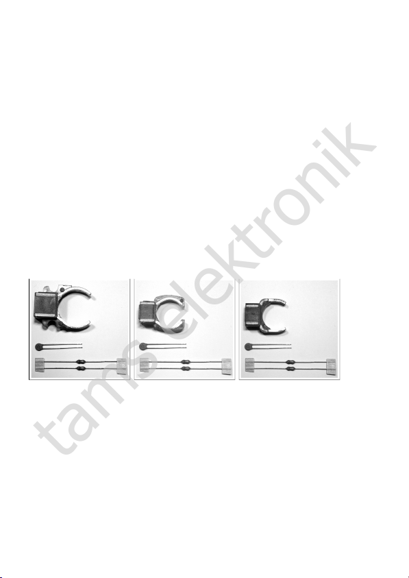
one permanent magnet
PM-1 (for large flat circle-shaped commutator motor) or
PM-2 (for small flat circle-shaped commutator motor) or
PM-3 (for drum-shaped commutator motor);
two mini chokes 3,3 µH;
one capacitor 1,5 or 1,8 nF;
this manual.
Required materials
For mounting and connecting the module you need:
an electronic soldering iron (max. 30 Watt) or a regulated soldering
iron with a fine tip and a soldering iron stand,
a tip-cleaning sponge,
a heat-resistant mat,
a small side cutter, wire stripper and a pair of tweezers,
electronic tin solder (0,5 mm diameter).
Page 15
tams elektronik
Page 5

English Motor modification set
2. Safety instructions
Mechanical hazards
Cut wires can have sharp ends and can cause serious injuries. Watch
out for sharp edges when you pick up the PCB.
Visibly damaged parts can cause unpredictable danger. Do not use
damaged parts: recycle and replace them with new ones.
Electrical hazards
Touching powered, live components,
touching conducting components which are live due to malfunction,
short circuits and connecting the circuit to another voltage than
specified,
impermissibly high humidity and condensation build up
can cause serious injury due to electrical shock. Take the following
precautions to prevent this danger:
Never perform wiring on a powered module.
Assembling and mounting the kit should only be done in closed,
clean, dry rooms. Beware of humidity.
Only use low power for this module as described in this manual and
only use certified transformers.
Connect transformers and soldering irons only in approved mains
sockets installed by an authorised electrician.
Observe cable diameter requirements.
After condensation build up, allow a minimum of 2 hours for
dispersion.
Use only original spare parts if you have to repair the kit or the
ready-built module.
Page 16
tams elektronik
Page 6

!
Motor modification set English
Fire risk
Touching flammable material with a hot soldering iron can cause fire,
which can result in injury or death through burns or suffocation.
Connect your soldering iron or soldering station only when actually
needed. Always keep the soldering iron away from inflammable
materials. Use a suitable soldering iron stand. Never leave a hot
soldering iron or station unattended.
Thermal danger
A hot soldering iron or liquid solder accidentally touching your skin can
cause skin burns. As a precaution:
use a heat-resistant mat during soldering,
always put the hot soldering iron in the soldering iron stand,
point the soldering iron tip carefully when soldering, and
remove liquid solder with a thick wet rag or wet sponge from the
soldering tip.
Dangerous environments
A working area that is too small or cramped is unsuitable and can cause
accidents, fires and injury. Prevent this by working in a clean, dry room
with enough freedom of movement.
Other dangers
Children can cause any of the accidents mentioned above because they are
inattentive and not responsible enough. Children under the age of 14
should not be allowed to work with this kit or the ready-built module.
Caution: Little children can swallow small components with
sharp edges, with fatal results! Do not allow components to reach
small children.
In schools, training centres, clubs and workshops, assembly must be
supervised by qualified personnel. In industrial institutions, health and
safety regulations applying to electronic work must be adhered to.
Page 17
tams elektronik
Page 7

!
English Motor modification set
3. Safe and correct soldering
Caution:
Incorrect soldering can cause dangers through fires and heat. Avoid
these dangers by reading and following the directions given in the
chapter Safety instructions.
Use a small soldering iron with max. 30 Watt or a regulated
soldering iron.
Only use electronic tin solder with flux.
When soldering electronic circuits never use soldering-water or
soldering grease. They contain acids that can corrode components
and copper tracks.
Solder quickly: holding the iron on the joints longer than necessary
can destroy components and can damage copper tracks or soldering
eyes.
Apply the soldering tip to the soldering spot in such a way that the
part and the soldering eye are heated at the same time.
Simultaneously add solder (not too much). As soon as the solder
becomes liquid take it away. Hold the soldering tip at the spot for a
few seconds so that the solder flows into the joint, then remove the
soldering iron.
Do not move the component for about 5 seconds after soldering.
To make a good soldering joint you must use a clean and unoxidised
soldering tip. Clean the soldering tip with a damp piece of cloth, a
damp sponge or a piece of silicon cloth.
After soldering, check the PCB tracks for solder bridges and short
circuits created by accident. This would cause faulty operation or, in
the worst case, damage. You can remove excess solder by putting a
clean soldering tip on the spot. The solder will become liquid again
and flow from the soldering spot to the soldering tip.
Page 18
tams elektronik
Page 8

Motor modification set English
4. Operation overview
Locomotive decoders designed to control alternating current (a.c.)
motors are – in contrast to decoders for direct current (d.c.) motors –
not load regulated (except few versions). In order to control a.c. motors
with a load regulated decoder (for d.c. motors) you can exchange the
field coil for a permanent magnet, thus converting the a.c. motor into a
d.c. motor.
The motor modification set contains a permanent magnet, suitable for
use with one of the different motor types (large or small flat circleshaped commutator motor or drum-shaped commutator motor),
depending on the version (PM-1, PM-2 or PM-3). Note: With some
locomotive models rotors and engine plates have been mounted not
fitting to any of the three versions of the permanent magnet.
As a matter of principle interference voltages occur with all locomotive
motors transmitting the voltage from the turning rotator via brushes. In
order not to disturb broadcast and TV reception, factory-made there
are suppression devices mounted at the locomotive motor.
The interference voltages (the so-called "brush-sparking") rise with
increasing abrasion. They can disturb the data transfer to the
locomotive decoder (and thus affect the driving characteristics). It is
even possible that the emerging current-peaks damage components on
the decoder. For that reason it is generally recommended to mount
suppression devices in addition to those mounted by the l ocomotive
manufacturer when mounting a permanent magnet into a priority
locomotive model.
Page 19
tams elektronik
Page 9

English Motor modification set
5. Technical specifications
Set 1 / PM-1 Set 2 / PM-2 Set 3 / PM-3
diameter 24,5 mm 18 mm 18 mm
weight 141 g 52 g 55 g
for motor
type
large flat circle-
shaped
commutator motor
small flat circleshaped
commutator motor
drum-shaped
commutator
motor
for rotor* 217450 200680 231440
for engine
plate*
211990, 216730,
228500
204900 231350
* The item-numbers for rotors and engine plates refer to Märklin** products.
6. Converting the motor
Preliminary work
Desolder the connection from the field coil to the engine plate
(directly on the engine plate).
If present: desolder the noise suppression choke. Tip: You can solder
this choke into the input lead from the slider to the locomotive
decoder and thus improve the noise suppression.
If present: desolder the noise suppression capacitors, discluding the
one at the motor (between the motor connections).
Take out the brushes. When doing so lift the pressure springs
cautiously to the side!
Release both screws at the engine plate and take out the engine
plate.
Take out the rotator cautiously! Tip: Use this opportunity to
overhaul the motor.
Take out the field coil. It will not be needed any more.
Note: Rotor and field coil are held to their position by the engine plate.
Page 20
tams elektronik
Page 10

Motor modification set English
Fig 1: Flat circle-shaped commutator motor with field coil (before
modification). The noise suppression choke mounted by the locomotive
manufacturer cannot be seen, it has to be dismounted.
Fig. 2: Drum-shaped commutator motor with permanent magnet (after
modification). The noise suppression capacitors mounted by the
locomotive manufacturer have been dismounted already.
Page 21
tams elektronik
Page 11
!
English Motor modification set
Mounting the permanent magnet
Install the permanent magnet instead of the field coil. Attention:
Do not apply force when installing the magnet. If necessary check if
you have to turn the magnet or if you have chosen the wrong type
(e.g. instead of a magnet for a small flat circle-shaped commutator
motor a magnet for a drum-shaped commutator motor).
Insert the rotor, attach the engine plate and fix it with both screws.
This fixes the permanent magnet, too. Attention: Do not tighten
the screws too firmly! The engine plate made of plastic could be
damaged and / or the engine running could be obstructed.
Insert the brushes and put the pressure springs cautiously onto the
brushes.
Mounting additional suppression devices
Solder the additional suppression chokes (included in the package)
into the two input leads from the decoder to the motor.
Solder the additional suppression capacitor (included in the package)
on to the engine plate. If a capacitor soldered in by the locomotive
manufacturer is present, solder the additional capacitor in parallel to
it.
Attention:
When the motor is not supressed sufficiently, the interference signals
affect the data transfer to the decoder. This affects the locomotive´s
driving characteristics (e.g. rocking or bucking). It is even possible
that the emerging current-peaks damage components on the decoder.
When brushes, the rotor or the motor are intensely worn, mounting
additional suppression devices is not sufficient to absorb the occuring
interference signals. In these cases you have to exchange the
components in question.
Page 22
tams elektronik
Page 12

!
Motor modification set English
Testing
Before mounting a locomotive decoder, you should always check with
your hand if the wheels turn easily. If not, maybe the screws at the
engine plate have been tightened too firmly or the rotor has been
incorrectly mounted.
Attention:
With stiff wheels the motor current will be increased. A too high motor
current can cause (irreparable) damages at the locomotive decoder!
7. Help with technical problems
Hotline: If problems with your motor modification set occur, our
hotline is pleased to help you (mail address on the cover page).
Sending in defective parts: You can send in defective parts for
checking (address on the cover page). In case of guarantee the
replacement is free of charge for you.
Please do not send in modules for checking charged to us. In case of
warranty we will reimburse the forwarding expenses up to the flat rate
we charge according to our valid price list for the delivery of the
product. With replacement deliveries not covered by guarantee you
have to bear the expenses for sending back and forth.
8. Guarantee bond
For this product we issue voluntarily a guarantee of 2 years from the
date of purchase by the first customer, but in maximum 3 years after
the end of series production. The first customer is the consumer first
purchasing the product from us, a dealer or another natural or juristic
person reselling or mounting the product on the basis of selfemployment. The guarantee exists supplementary to the legal warranty
of merchantability due to the consumer by the seller.
Page 23
tams elektronik
Page 13

English Motor modification set
The warranty includes the free correction of faults which can be proved
to be due to material failure or factory flaw. With kits we guarantee
the completeness and quality of the components as well as the function
of the parts according to the parameters in not mounted state. We
guarantee the adherence to the technical specifications when the kit
has been assembled and the ready-built circuit connected according to
the manual and when start and mode of operation follow the
instructions.
We retain the right to repair, make improvements, to deliver spares or
to return the purchase price. Other claims are excluded. Claims for
secondary damages or product liability consist only according to legal
requirements.
Condition for this guarantee to be valid, is the adherence to the
manual. In addition, the guarantee claim is excluded in the following
cases:
if arbitrary changes in the circuit are made,
if repair attempts have failed with a ready-built module or device,
if damaged by other persons,
if damaged by faulty operation or by careless use or abuse.
9. EU declaration of conformity
This product conforms with the EC-directive mentioned below
and is therefore CE certified.
2011/65/EG on the restriction of the use of certain hazardous
substances in electrical and electronic equipment (ROHS). Underlying
standard: EN 50581.
Page 24
tams elektronik
Page 14

n
n
n
Aktuelle Informationen und Tipps:
Information and tips:
n
Informations et conseils:
Actuele informatie en tips:
n
http://www.tams-online.de
n
n
n
Garantie und Service:
Warranty and service:
n
Garantie et service:
Garantie en service:
n
Tams Elektronik GmbH
n
fon: +49 (0)511 / 55 60 60
fax: +49 (0)511 / 55 61 61
n
e-mail: modellbahn@tams-online.de
n
n
tams elektronik
 Loading...