

tams elektronik
Manual
Digital Control Unit
for EasyControl Digital System
Item no. 40-03007
tams elektronik
n n n

Notes on this download version of the manual
This manual provides you with an overview of the features and functions of the digital central
unit mc². However, the manual is only one part of the instructions. Another essential part is
the direct help in the web interface of the central unit, the so-called mc²-Toolbox. You can
connect to a real mc² digital central unit via the Internet and test the web interface.
Link to the mc²-Toolbox
Notes for users of the digital central unit mc²
This download version of the manual may not correspond to the software and/or hardware
version of your mc². Please only use the version of the manual that is available for download
in the mc²-Toolbox.
Version 1.01 05/2021
This manual is part of the user software "mc²-Toolbox" and applies to:
Hardware of the mc²: Version 1.4
Firmware of the mc²: Version 1.03
Software for web interface mc²-Toolbox: Version 1.10
© Tams Elektronik GmbH
All rights reserved, in particular the right of reproduction, distribution and translation. Copies,
reproductions and alterations in any form require the written permission of Tams Elektronik
GmbH. We reserve the right to make technical changes.
Updates
Download the latest version of the manual after you have performed an update of the mc²Toolbox (the software for the web interface of the mc²). Appendix B contains an overview of
the changes and additions to the manual.
Printing the manual
The formatting is optimised for double-sided printing. The standard page size is DIN A5. If you
prefer a larger display, printing on DIN A4 is recommended.
0.2 | mc²

tams elektronik
Contents
1. Getting started........................................................................................................1.1
2. Commissioning........................................................................................................2.1
3. Your mc²................................................................................................................3.1
3.1. Display and operating elements.......................................................................3.3
3.2. Protocols........................................................................................................3.4
3.3. Virtual control devices.....................................................................................3.5
3.4. External digital input devices...........................................................................3.6
3.5. Boosters.........................................................................................................3.7
3.6. PC control.......................................................................................................3.8
4. Connections............................................................................................................4.1
4.1. Main and programming track...........................................................................4.2
4.2. Connection of external digital devices...............................................................4.3
4.2.1. Devices for the CAN bus.........................................................................4.3
4.2.2. Devices for the LocoNet.........................................................................4.4
4.2.3. Devices for the EasyNet.........................................................................4.5
4.2.4. Devices for the XpressNet......................................................................4.6
4.2.5. Digital central units for DCC and Motorola...............................................4.7
4.3. Connecting BiDiB devices.................................................................................4.8
4.4. Connection of s88 feedback modules................................................................4.9
4.5. Connection of external boosters.......................................................................4.10
4.6. Connection to the audio output........................................................................4.11
5. Configuring the system (Submenu "System")............................................................5.1
5.1. System Info....................................................................................................5.1
5.2. Vehicles..........................................................................................................5.3
5.3. Accessories.....................................................................................................5.4
5.4. Protocol..........................................................................................................5.5
5.5. Boosters.........................................................................................................5.6
6. Operation with the mc²...........................................................................................6.1
6.1. Operating and display elements.......................................................................6.1
6.1.1. STOP and GO buttons............................................................................6.1
6.1.2. Display and RGB-LEDs...........................................................................6.2
Contents| 0.3
tams elektronik
6.2. Submenu "Operation"......................................................................................6.4
6.2.1. Feedback..............................................................................................6.4
6.2.2. Programming........................................................................................6.5
6.2.3. Messages..............................................................................................6.7
6.2.4. BiDiB....................................................................................................6.7
6.2.5. Control..................................................................................................6.8
6.2.6. Model time............................................................................................6.8
6.3. Virtual control devices.....................................................................................6.9
6.3.1. HandControl.vi......................................................................................6.9
6.3.2. FunctionControl.vi..................................................................................6.11
6.3.3. DriveControl.vi.......................................................................................6.12
6.3.4. SwitchControl.vi.....................................................................................6.13
7. Updates..................................................................................................................7.1
8. Checklist for troubleshooting....................................................................................8.1
8.1. Heat generation..............................................................................................8.1
8.2. Automatic safety shutdown..............................................................................8.1
8.3. Problems with the power supply.......................................................................8.2
8.4. Problems with external input devices................................................................8.2
8.5. Problems when programming and controlling vehicles.......................................8.3
8.6. Problems when switching points and other accessories......................................8.4
8.7. Problems with s88 modules.............................................................................8.4
8.8. Problems with the software update..................................................................8.5
8.9. Technical hotline.............................................................................................8.5
8.10. Repairs...........................................................................................................8.5
9. Technical data.........................................................................................................9.1
9.1. Digital control unit mc²....................................................................................9.1
9.2. Power supply unit...........................................................................................9.4
10. Warranty, EC Conformity & WEEE............................................................................10.1
10.1. Warranty Statement........................................................................................10.1
10.2. EC Declaration of Conformity...........................................................................10.2
10.3. Declarations on the WEEE Directive..................................................................10.2
Appendix A: Organisations, Manufacturers, Products..............................................................
Appendix B: Changes and additions.......................................................................................
0.4 | Contents
tams elektronik
1. Getting started
The instructions for the digital central unit mc² consist of the following parts:
the guide, which is enclosed with the delivery in printed form and which contains all the
information you need for safe and proper commissioning of the mc². The contents of the
guide are also included in this manual. Nevertheless, keep the guide carefully in case you
want to commission the mc² again and do not have access to the manual. If you pass the
digital central unit on to another person, also give the guide with it.
this manual, which is available for download in the mc²-Toolbox (the web interface of the
central unit). In the manual you will find all the information you need for safe and proper
connection to your system and external devices, as well as an overview of the configuration
of your mc² and instructions for operation. Note: The manual applies to the software
version(s) of the mc² indicated on page 0.2 of this manual.
the direct help in the mc²-Toolbox
Contents of the package
After unpacking, check the delivery for completeness:
mc² digital control unit
power supply unit
mains cable (black) with Euro plug (CEE 7/16) and plug for mains cable socket (European
version / C7)
connection cable (grey) with RJ-45 connectors (at least Cat. 5e)
one 4-pole plug for connection to main and programming track and one 3-pole plug for
connection to external boosters
4 plastic brackets for mounting the mc²
this guide and sticker sheet for labelling the connection cables
Required additional equipment
It is not possible to use the mc² digital control unit without additional devices. You can use the
following devices for commissioning, configuration and operation of the model railway layout:
Commissioning Configuration Operation
PC X X X
Tablet
(and WLAN router)
Smartphone
(and WLAN router)
HandControl 2 ---
Other digital control
devices
X X X
X
--- --- X
X
(not recommended)
X
(restricted)
X
X
Getting started | 1.1

tams elektronik
Intended use
The digital control unit mc² is intended for controlling digital model railway layouts according
to the information in the instructions (consisting of guide, manual and direct aids). Only the
power supply unit included in the scope of delivery is permitted for the power supply. Any
other use is not in accordance with the intended use and will result in the loss of the warranty
claim. Intended use also includes reading, understanding and following all parts of the
instructions. The mc² is not intended to be used by children under the age of 14.
Safety instructions
Improper use and non-observance of the instructions can lead to incalculable hazards. Prevent
these dangers by carrying out the following measures:
Use the digital control unit and the power supply unit only in closed, clean and dry rooms.
Avoid humidity and splash water in the environment. After condensation has formed, wait
two hours for acclimatisation before use.
Disconnect the control unit from the power supply before carrying out wiring work.
Only plug the mains plug of the power supply unit into properly installed and fused earthed
sockets.
Heating of the control unit and the power supply unit during operation is normal and
harmless. Keep a distance of at least 20 cm between the sides, the top and the back to
surrounding surfaces to allow unhindered air exchange and to predect the units from
overheating.
Do not expose the units to high ambient temperatures or direct sunlight. Observe the
information on the maximum operating temperature in the technical data.
Regularly check the operational safety of the units, e.g. for damage to the connection
cables or damage to the housing.
If you notice damage or if malfunctions occur, switch off the supply voltage immediately.
Send in the control panel and/or the power supply unit for inspection.
Dangerous voltages occur inside the power supply unit. Therefore, never open the housing
of the power supply unit.
Care
Do not use any cleaning agents to clean the mc² and the power supply unit. Only wipe the
units dry. Disconnect the units from the power supply before cleaning.
1.2 | Getting started
tams elektronik
2. Commissioning
After commissioning, you must first configure your mc², i.e. adapt it to your ideas and adjust it
to the conditions of your model railway layout. It is therefore not recommended to start up the
mc² with a smartphone, as the display of the mc²-Toolbox (the web interface of your control
unit) is unclear due to the small screen size.
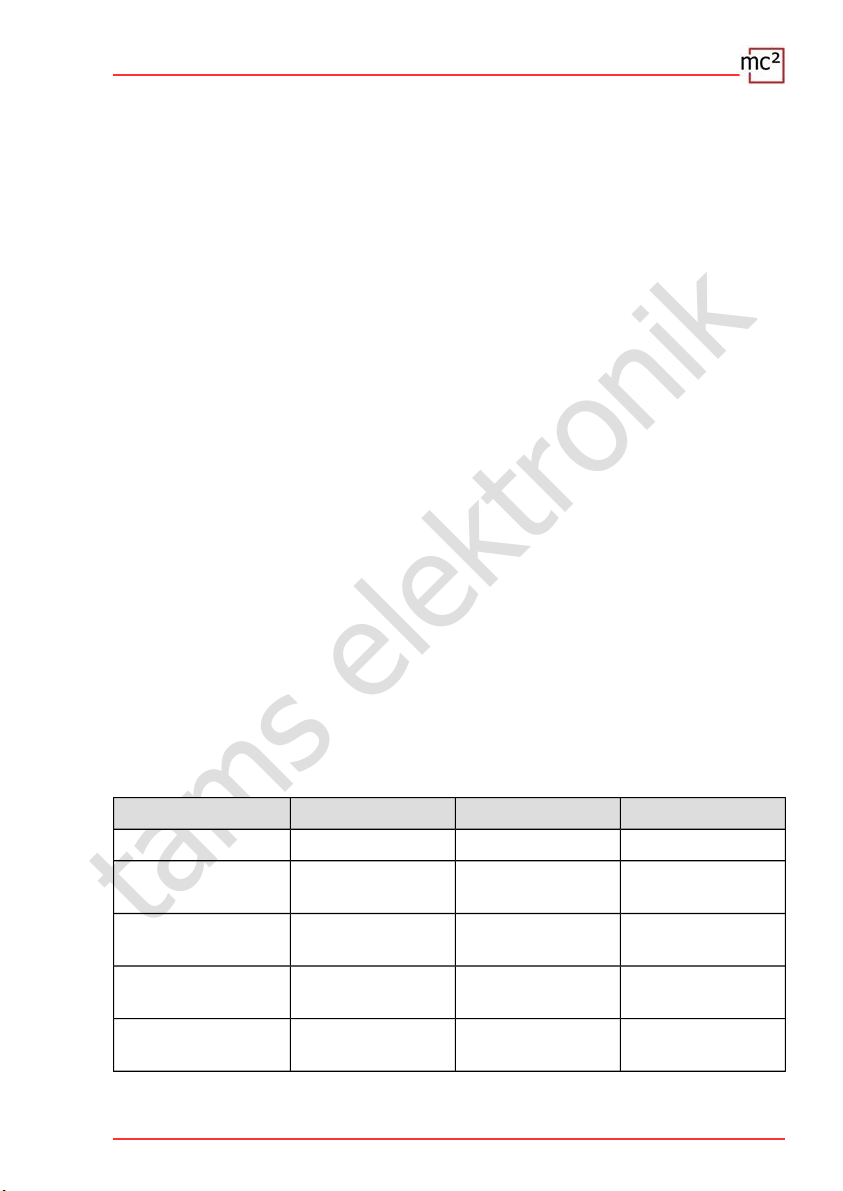
Direct connection to the PC
You can connect your mc² directly to your PC.
Plug the (grey) patch cable on one side
into the LAN interface of the mc² and on
the other side into the RJ45 socket of the
network interface of your computer.
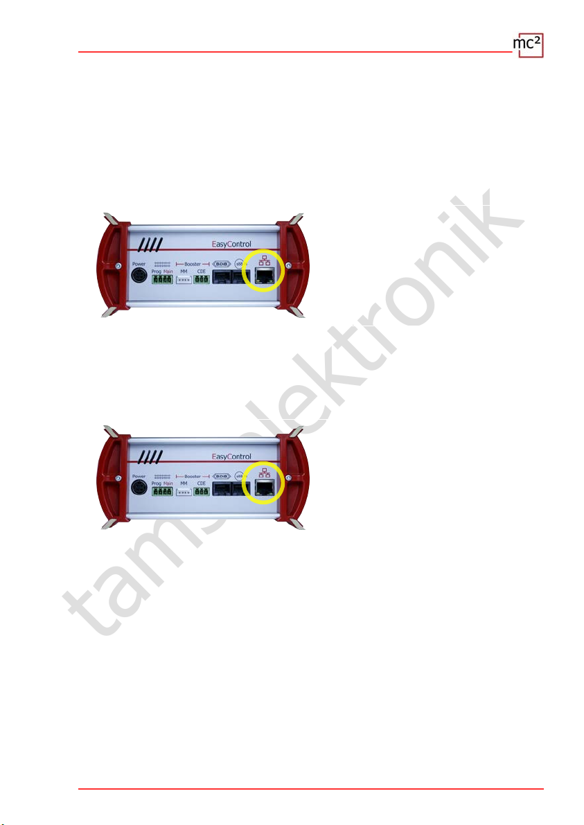
Connecting to the Intranet / Internet
By connecting your mc² to your router, you can use devices such as a PC, tablet or
smartphone that also have a connection to the router to configure your mc² and control your
system. You can also use the router to connect to the Internet, which you need to check for
updates.
Plug the (grey) patch cable into the LAN
interface of the mc² on one side and into
a free RJ45 socket of the router on the
other side.
Commissioning | 2.1
tams elektronik
!
!
Connection to the power supply
Note:
Only use the power supply unit supplied as a power supply for your mc² and the
components of your system that are supplied by the integrated booster.
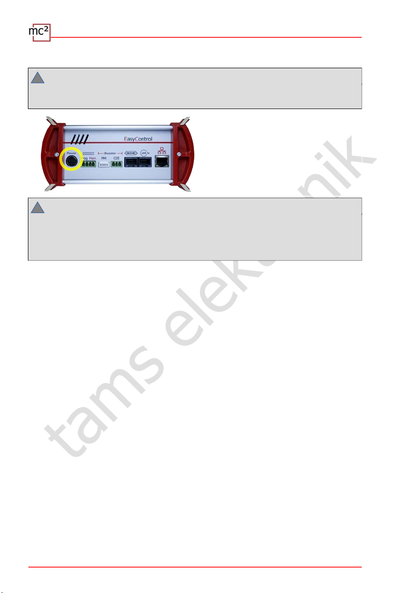
First, plug the 4-pin connector of the
power supply connection cable into the
"Power" socket on the back of the mc² so
that the flat part of the plug points
upwards.
Note:
There is a catch on the unit plug that prevents the power supply connection cable from
being pulled out accidentally. To be able to pull out the cable, you must pull the catch in the
direction of the cable. Never pull the cable out of the socket by force! Doing so may damage
connections in your mc².
Then plug the supplied (black) mains cable into the connection socket of the power supply
unit and into the socket.
Reading out the IP address of the mc²
Press and hold the "GO" button of the mc² until "IP" is shown in the display. If you continue
to press the "GO" key, the digits of the IP address appear one after the other. Tip: Write
down the digits including the dots.
Structure of the IP address: 123.456.789.123
Note: Leading zeros (after a dot) are not shown in the browser display.
Calling up the IP address in the browser
The mc²-Toolbox (i.e. the web interface of the mc²) has been tested with the browsers
Chrome, Firefox, Opera and Edge. The use of the browsers Internet Explorer and Safari is not
recommended, as they do not support all the required functions.
Enter the read IP address in the browser of the PC, tablet or smartphone. The start page
("Home") of the mc²-Toolbox will then open.
2.2 | Commissioning
tams elektronik
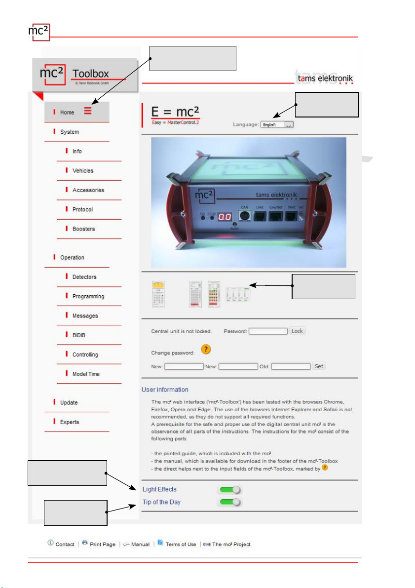
User settings in the mc²-Toolbox
Set the following on the start page of the web interface of your mc²:
longuage
Display of the submenu items: Change the display by clicking on the symbols.
Submenu items are always displayed
Submenu items are only displayed after clicking on the
higher-level main menu item.
Downloading the manual
Before connecting the mc² to your model railway layout, download the manual from the start
page of the mc²-Toolbox ("Home") and read it carefully. In the manual you will find all the
information you need to connect to your layout and external devices, as well as an overview of
the configuration of your mc² and notes on its operation.
In the manual you will also find the troubleshooting checklist, the technical data of the control
unit and the power supply unit and the warranty declaration.
Before the first test drive
For a first test run you can connect your mc² e.g. to a separate track oval, for which the
integrated booster is sufficient as a power supply, and familiarise yourself with the functions of
the control unit.
You have to do the following things before you can do a first round with a locomotive:
Connect the track output of the mc² to the rails (→ section 4.1 in the manual).
Configure the integrated booster, i.e. set the track voltage and the maximum current for
the nominal width of your layout (→ menu item "System / Boosters").
To control a locomotive, proceed as follows:
DCC decoder: Open the virtual HandControl on the start page ("Home") of the mc²-
Toolbox. Enter the DCC address and control the locomotive. For the functionality of the
HandControl.vi → section 6.3.1 in the manual.
MM decoder: Before you can control a locomotive with the HandControl.vi, you must create
the MM address in the locomotive list and assign an MM format to the locomotive (→ menu
item "System / Vehicles").
mfx decoder: First read out the UID and assign an address to the decoder (→ menu item
"Operation / Programming / m3"). You can then control the locomotive in m3 format with
HandControl.vi.
Commissioning | 2.3
tams elektronik
2.4 | Commissioning
Setting the display
of the submenu
Selecting
the language
Virtual
control units
(De)activating
"Boredom Mode"
(De)activating
Tip of the Day

tams elektronik
3. Your mc²
The main tasks of your mc² include,
to send the digital driving and switching commands to the vehicle and accessory decoders
to receive and forward the feedback signals from decoders and feedback units
to serve as a "medium" for programming the decoders.
Furthermore
a booster is integrated in your mc², which brings the digital signals to the track and
supplies the vehicles with power.
your mc² acts as an interface to various additional devices such as external input devices,
feedback devices, PC and mobile devices.
Browser-based
Your mc² uses the possibilities offered by PCs, mobile devices such as smartphones or tablets
and fast Internet in private households.
The web interface "mc²-Toolbox", i.e. the software with which you configure your digital
control and control your system, is called up via the browser of a PC, tablet or smartphone.
You then have access to all functions of the mc². The mc²-Toolbox is installed on your mc²
and you can perform updates for it in the same way as for the firmware of the central unit.
You do not need to install any software or app on your PC or mobile devices. The question of
whether the operating systems of the various devices are compatible with each other is
therefore irrelevant.
You can connect the mc² to your home network and the Internet via a router. Connection to a
Wlan router is a prerequisite for the use of mobile end devices. Alternatively, you can connect
a PC directly to your mc² (without a diversion via a router). An Internet connection is only
absolutely necessary if updates are to be requested.
The mc² Toolbox
With the Toolbox (the web interface of the mc²) you manage your digital control including all
connected input devices, feedback devices and boosters. You can
configure your mc², i.e. adapt it to your ideas and the conditions of your layout
programme your vehicle and accessory decoders
manage your feedback devices and query messages from the various data buses (BiDiB,
s88, Märklin-CAN, LocoNet)
display RailCom messages
carry out updates
Your mc² | 3.1

tams elektronik
Input and control devices
For the control of your layout you have various possibilities open to you, which you can also
combine with each other as you wish:
virtual control devices that you open on your smartphone, tablet or PC (→ section 3.3)
digital input devices from various manufacturers (→ section 3.4)
special PC control software (→ section 3.6)
3.2 | Your mc²
tams elektronik
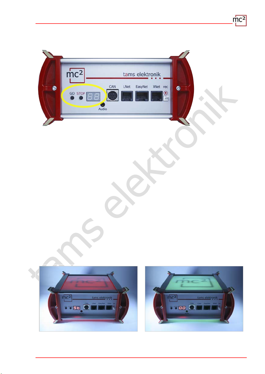
3.1. Display and operating elements
STOP & GO
These two buttons of the mc² are used
to switch the track voltage on and off
to trigger a reset
as a trigger for displaying the IP address
to delete the internal configuration
Display
The 2-digit 7-segment display shows you essential information, e.g.
the current consumption in the booster circuit of the internal booster
the operating status (short circuit, stop, normal operation)
the IP address (due to the limitation to 2 display fields in several "sequences")
the progress of an update
RGB LEDs in the housing
The top and bottom of the mc² are made of translucent plastic. During operation, RGB LEDs
built into the housing visibly indicate the operating status of the mc² from a distance, e.g.
green for "normal operation" or red for "stop, track voltage is switched off".
Track voltage = off Track voltage = on
Your mc² | 3.3

tams elektronik
3.2. Protocols
Digital formats
The mc² sends digital driving and switching commands to the vehicle and accessory decoders
in the following formats:
DCC: 14, 28 or 128 speed steps
Motorola: I and II (14 or 28 speed steps)
m3: This format enables the control of vehicle decoders for the mfx protocol. Note:
Automatic registration of mfx decoders with the command station is not possible.
BiDiB
The mc² is simultaneously a BiDiB interface and BiDiB track output device in the sense of the
BiDiB specification.
Up to 31 nodes of one level can be connected to the BiDiB interface of the mc². With
appropriate PC control software, digital commands can be sent and messages received and
evaluated via the BiDi bus.
CAN, EasyNet and XpressNet
These protocols exclusively define the communication between input devices (e.g. hand
controllers) and the mc², but not the transmission of digital commands or feedback signals.
DCC-A
The RailCom-based extension of the DCC format enables the automatic registration of vehicle
decoders with the control centre. Currently (as of April 2021), a draft standard is available
from the RailCommunity, which is expected to be adopted in the course of 2021.
LocoNet
In a later software version it will be possible to send switching commands via LocoNet and to
evaluate feedback from LocoNet. The update will be available for download free of charge.
RailCom
A global RailCom detector is integrated in the mc², which receives the messages from the
RailCom decoders and forwards them to the PC. For forwarding the RailCom messages to the
PC control software, the mc² uses the BiDiB protocol.
s88
Up to 52 s88 or s88-compatible modules (= 832 contacts) can be connected to the s88
interface. Note: The s88-compatible modules also include, for example, feedback devices that
are connected via the CAN bus interface.
Data transmission to the PC
For information on the protocols used for data transmission between the mc² and the PC, see
section Fehler: Referenz nicht gefunden.
3.4 | Your mc²
tams elektronik
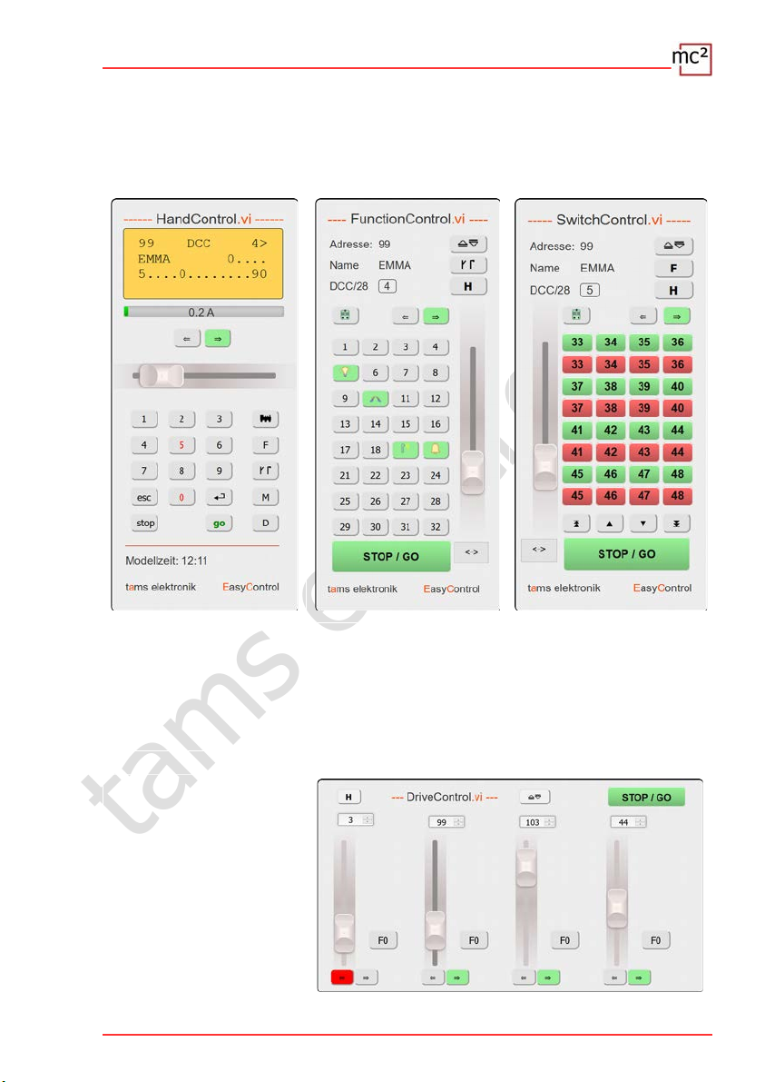
3.3. Virtual control devices
From the Toolbox, you have access to various virtual control devices to control your layout.
The virtual control devices are optimised for use with smartphones or tablets, but can just as
easily be used from the PC screen.
The HandControl.vi is similar
to the real HandControl.2
and can be used to call up
vehicles and switch functions
up to F9.
With DriveControl.vi,
4 locomotives can be
accessed simultaneously.
The speed level can be set,
the direction of travel can be
changed and the F0 function
can be switched on and off.
With the FunctionControl.vi
locomotives can be
controlled sensitively and
functions up to F32 can be
switched.
The SwitchControl.vi is
intended for switching
turnouts (or other stationary
components). The last
locomotive called up remains
under control.
Your mc² | 3.5
tams elektronik
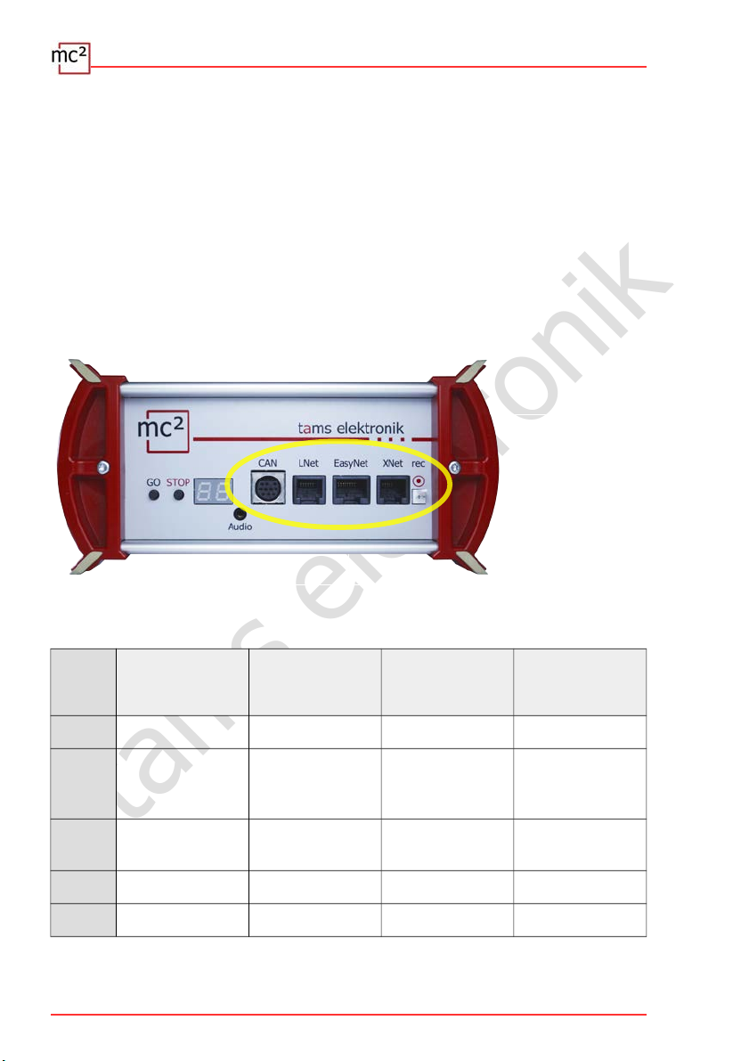
3.4. External digital input devices
The mc² has interfaces for various digital input devices from different manufacturers. You can
integrate manual control units and/or digital control centres for the following bus systems into
your digital control:
Märklin CAN-Bus
LocoNet
XpressNet
EasyNet
Via the universal interface "rec" you can also integrate all digital control units for the DCC or
Motorola format that have a track output into the EasyControl system and use them as
external control and switching devices.
Possible applications for external digital input devices
Driving
(controlling vehicle
decoders)
Switching
(controlling accessory
decoders)
Programming
(programming
decoders)
Configuring
(setting up the digital
system control / mc²)
CAN X X --- ---
LNet X
not yet
implemented
(Status 04/2021)
--- ---
EasyNet X X X
possible
(with limitations)
XNet X X X (POM only) ---
rec X X --- ---
3.6 | Your mc²
tams elektronik
3.5. Boosters
Integrated booster
A booster is integrated in the mc², which can provide a maximum of 6.5 A current. This
current is usually sufficient for the operation of layouts of all nominal sizes. Depending on the
nominal size, the maximum output current must be limited.
Short-circuit sensitivity: 1 - 6.5 A. It can be adapted to the nominal size of the installation in
steps of 0.5 A.
Track voltage: 8 - 22 V. It can be adjusted in steps of 1 V.
Track signal: symmetrical
RailCom cutout: can be switched off.
The status messages of the integrated booster are reported to the control software via BiDiB.
They are then available as a basis for booster management.
External boosters
If one booster circuit is not sufficient for the operation of the layout, or if the signals for
vehicle and accessory decoders are to be output separately, additional external boosters can
be connected. Both Märklin-compatible boosters and DCC-compliant boosters can be used.
Boosters conforming to the BiDiB specification or boosters for use in LocoNet can be
connected directly to the corresponding interfaces. The use of different booster types for
separate parts of the layout or separately for the tasks "driving" and "switching" is basically
possible.
Output of the driving and switching commands
For the track output of the integrated booster and the interfaces for Märklin-compatible and
DCC-compliant boosters it is set separately whether
driving and switching commands or
only driving commands
are to be output. The setting for the integrated booster also applies to boosters on the BiDiB
and LocoNet interfaces.
Your mc² | 3.7

tams elektronik
3.6. PC control
Protocols: BiDiB or p50x
For the encryption of the data exchanged between the central unit and the PC control
software, the mc² uses the BiDiB protocol or - if this is not supported by the software - the
p50x protocol.
With software that supports BiDiB, all the possibilities offered by bidirectional communication
via the BiDiBus can be used. These include e.g.:
the direct sending of digital commands to the stationary BiDiB nodes via the BiDiBus cables
(e.g. to the accessory decoders)
receiving feedback from the stationary BiDiB nodes (e.g. from boosters and accessory
decoders).
the reception of messages from the global RailCom detector integrated in the mc².
If these possibilities are utilised, the safety and the transmission speed in PC-controlled
systems are significantly increased.
If the BiDiB protocol is not supported by the PC control software, the data transmission
between mc² and PC is automatically carried out via the p50x protocol. BiDiB nodes can then
not be used or only to a limited extent. BiDiB feedback modules are treated like s88
feedbacks, for example. The transmission of RailCom messages of the integrated global
RailCom detector to the PC control software is then not possible.
TCP to TCP
By default, the data is transmitted from the mc² to the PC or router via the LAN interface
using the network protocol TCP ("Transmission Control Protocol"). Whether the data is
encrypted in the BiDiB or p50x protocol is irrelevant. Many newer versions of model railway
control programs support TCP.
TCP to COM: Setting up a virtual COM port
With older model railway control programmes or older versions of the control programmes,
the data transfer between PC and digital control unit is usually based on the RS-232 standard
for serial interfaces. In most cases, these programmes use only the p50x protocol for
encoding the data.
The prerequisite for using these programmes is the setting up of a virtual serial interface (or
in other words: a virtual COM port). Various programmes are available on the internet for this
purpose, with the help of which a driver for a virtual COM port can be set up on the PC.
3.8 | Your mc²
tams elektronik
4. Connections
Danger of confusion!
!
Note that identical plug connections are used for different bus systems:
RJ12: LocoNet and XpressNet
RJ45: EasyNet, BiDiB, S88-N and LAN
Therefore, be very careful when plugging in the connection cables! Make sure that you do
not accidentally plug the cables into the wrong sockets! In the worst case, (even irreparable)
damage can occur to your mc² and/or the connected devices. This applies especially to
EasyNet devices, s88 modules and BiDiB components.
If you plug connection cables with RJ12 plugs into RJ45 sockets, the connection pins in the
socket will be bent. In this case, we recommend sending in the central unit for repair.
Avoid these risks by marking the connection cables (e.g. with the labels enclosed with the
delivery) and/or using different coloured cables for the different bus systems, e.g.
red for EasyNet
blue for the s88 bus
green for the BiDi bus
grey for the Ethernet (Lan)
Plug & Play
You can establish or interrupt connections to and from external devices to your mc² at any
time - even during operation (plug and play).
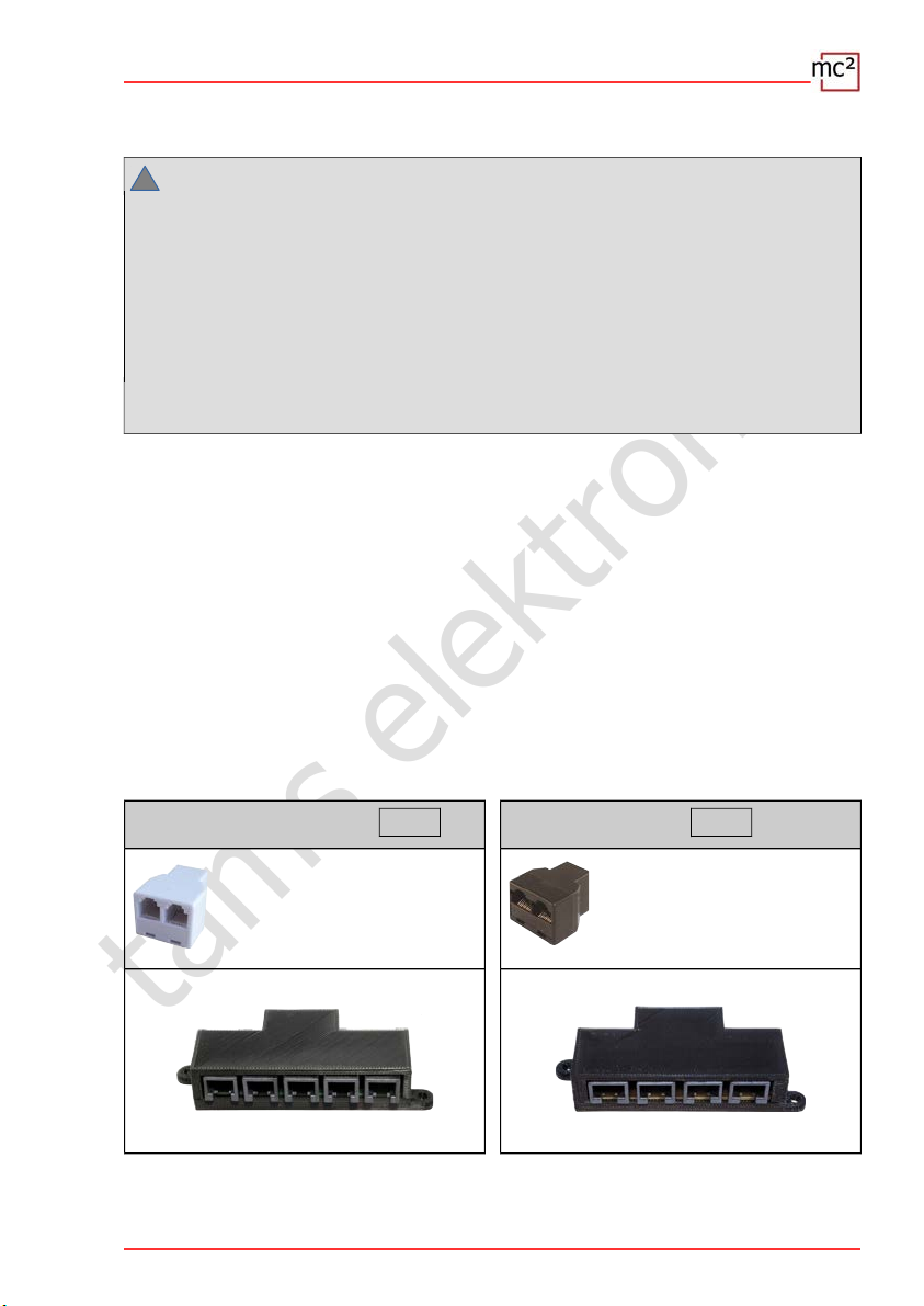
Distributors
To enable the use of several digital control units on one interface, you can use terminal blocks
or Y-distributors:
LocoNet and XpressNet RJ12 EasyNet RJ45
Y-distributor RJ12
(item no. 73-80493-01)
Input: 1 x RJ12
Output: 2 x RJ12
XL-Terminal block (item no. 73-80496-01)
Input: 1 x RJ12 | Output: 5 x RJ12
EasyNet-Termnal block (item no. 73-80195-01)
Input: 1 x RJ45 | Output: 4 x RJ45
Y-distributor RJ45
(item no. 73-80190-01)
Input: 1 x RJ45
Output: 2 x RJ45
Connections | 4.1
tams elektronik
!
!
4.1. Main and programming track
Connect the two track connections of the integrated booster
with the two rails (for 2-conductor systems) or
with one rail and the centre conductor (with 3-conductor systems).
The feeding of the booster current into the track should be done at a distance of approx. 2 to
3 m from a ring line, because the resistances at the transitions of the track sections are quite
high. If the distances are chosen too large, there may be problems with the short-circuit
feedback or with the power supply to the vehicles.
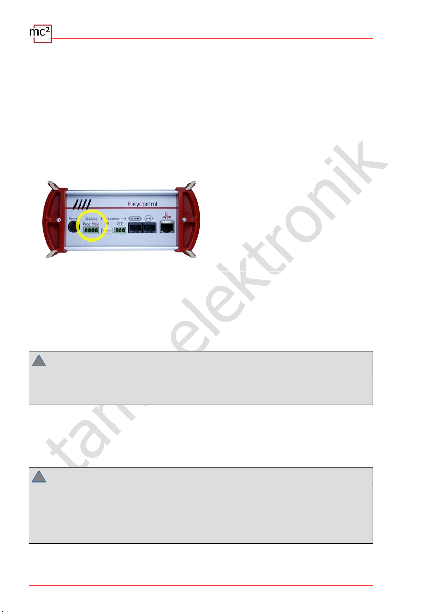
Use the 4-pin connector supplied to
connect the cables leading to the main
track ("Main") or to the programming track
("Prog").
Insert the connecting cables into the plug
part, screw them tight and then plug the
plug part onto the socket on the back of
the mc² in such a way that the screws
point upwards.
Recommended cable cross-sections
Programming track: 0.75 mm²
Main track: 0.75 to 1.5 mm² (depending on the current)
Booster configuration
Hint:
Before you start operation on your layout, you must configure the booster (→ section 5.5).
If the track voltage and/or the max. current are set too high, damage to the tracks and/or
vehicles can occur during operation.
Programming track
You can use a separate piece of track as a programming track or a section of track on your
layout (e.g. a siding) that you can electrically separate from the rest of the layout during
programming.
Hint:
If you integrate the programming track into your model railway layout, you must ensure that
both tracks are electrically separated from the rest of the layout during programming.
Otherwise the programming track connection of the mc² can be damaged! In
addition, you will otherwise program all decoders on the layout that react to the set data
format.
4.2 | Connections
tams elektronik
4.2. Connection of external digital devices
4.2.1. Devices for the CAN bus
Info
The CAN bus is actually a data bus developed for the (car) industry and is used by various
model railway manufacturers for communication between digital devices. Note: The
manufacturers use different data protocols, therefore the devices of different manufacturers
cannot communicate with each other. The protocol of the CAN interface of the mc² is that of
the Märklin CAN bus.
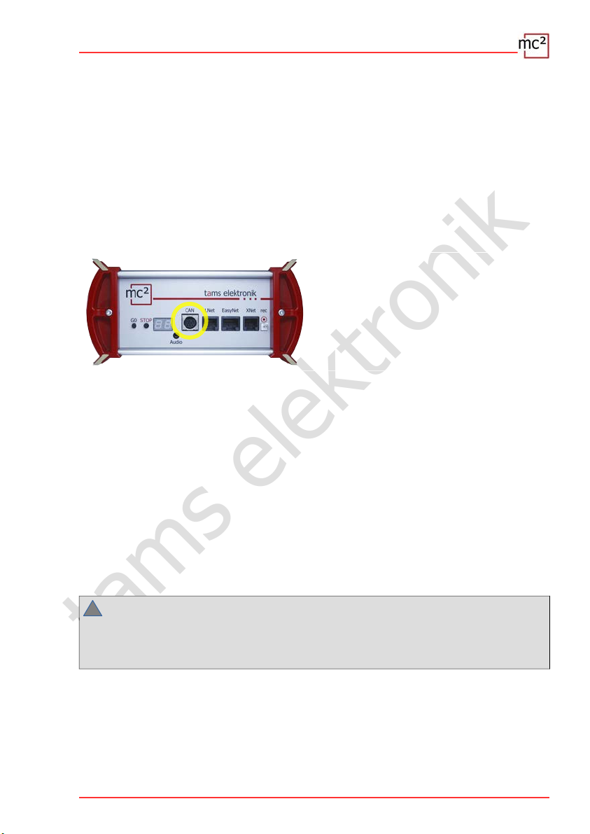
Connection: 10-pole
For the connection of
Mobile Station 2 and 3 (not MS 1)
Central Station 2 and 3 (configured as
"Slave")
Feedback units for the Märklin CAN bus
Note: The feedback units send their data via the CAN bus,
the data protocol corresponds to the s88 bus.
Possible applications of the CAN input devices
You can use the input devices that you integrate into the digital control system via the
interface for the CAN bus for
to control vehicle decoders for Motorola, DCC and mfx (the latter in m3 format) or
to switch accessory decoders for Motorola and DCC
However, it is not possible to program decoders or configure the digital system using CAN
input devices.
Power supply of the devices at the CAN interface
Devices such as the hand control units Mobile Station 2 and 3 are supplied with power via the
bus line. The Central Station 2 and 3 control units and feedback devices for the CAN bus have
their own power supplies.
Notice:
!
The total current of all external digital devices that are connected to the various interfaces of
the mc² and do not have their own power supply must not exceed 1.2 A. Otherwise, the mc²
automatically switches off the power supply for the external devices.
Connections | 4.3
tams elektronik
!
4.2.2. Devices for the LocoNet
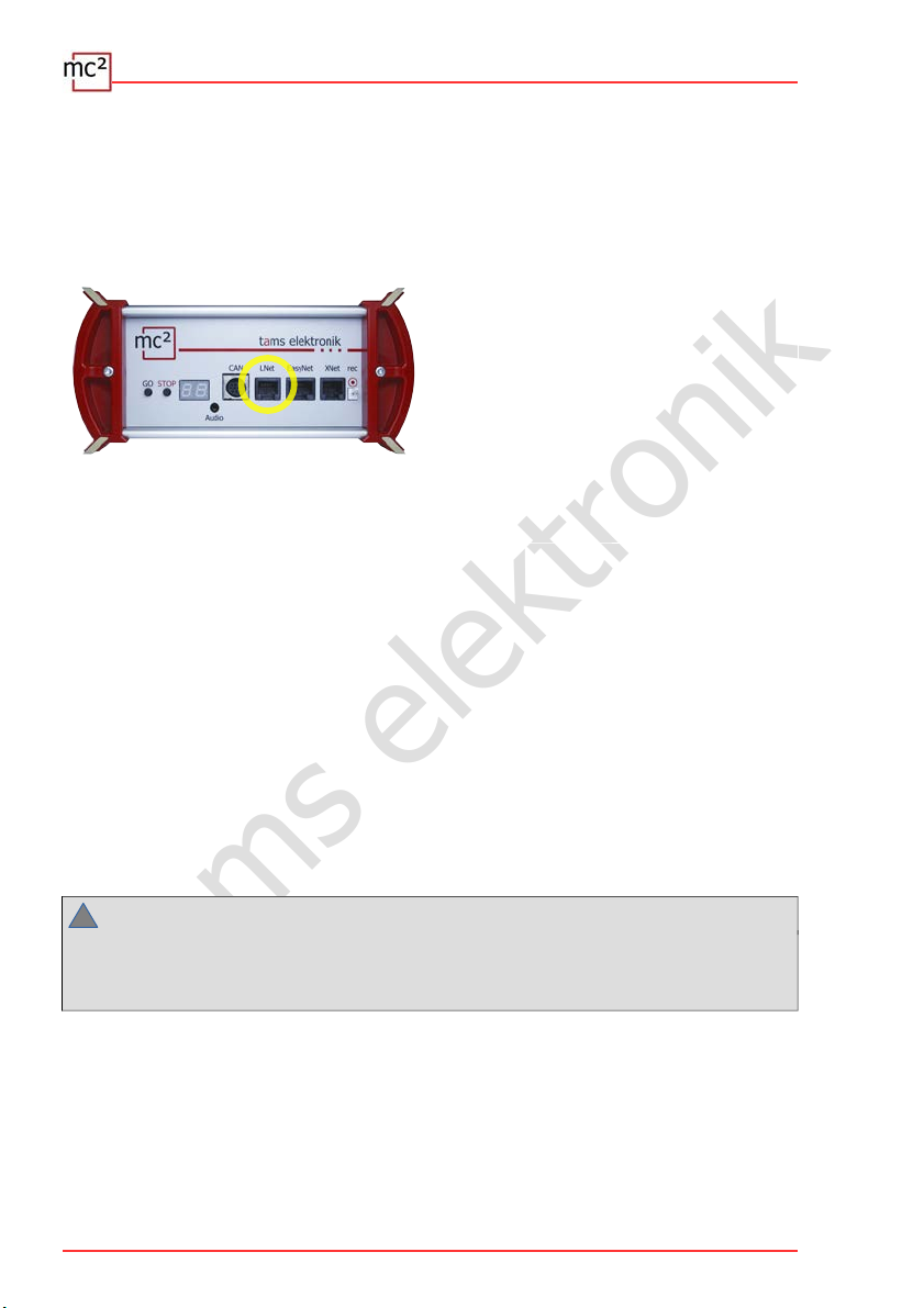
Info
The LNet connector allows the connection of digital devices whose data transmission is done
via the LocoNet developed by Digitrax.
Connection: RJ12
For the connection of
FRED hand controller from Uhlenbrock
DAISY 2 hand controller from Uhlenbrock
SmartControl light from Piko
LocoNet booster
LocoNet accessory decoder
LocoNet feedback
Note: The control of boosters and accessory decoders for
LocoNet as well as the forwarding of feedback signals from
LocoNet are not yet supported. (Status: 04/2021).
Possible applications of the LocoNet input devices
You can use the input devices that you integrate into the digital control system via the
LocoNet interface
to control vehicle decoders for Motorola, DCC and mfx (the latter in m3 format) or
to switch accessory decoders for Motorola and DCC
However, it is not possible to program decoders or configure the digital system using LocoNet
input devices.
Power supply of the devices at the LocoNet interface
LocoNet handheld control devices are usually powered via the bus line. Other LocoNet digital
devices such as command stations, boosters or accessory decoders have their own power
supplies.
Notice:
The total current of all external digital devices that are connected to the various interfaces of
the mc² and do not have their own power supply must not exceed 1.2 A. Otherwise, the
mc² automatically switches off the power supply for the external devices.
4.4 | Connections

tams elektronik
4.2.3. Devices for the EasyNet
Info
The EasyNet is the data bus for the EasyControl digital system. Devices and adapters that have
been specially developed for this system communicate via this bus.
Connection: RJ45
For the connection of
HandControl and HandControl 2
LokControl
MasterControl (with configuration as
"slave")
mControl
Note: The connection of the adapters XNControl, SniffControl or wControl does not make
sense, as corresponding interfaces are integrated in the mc².
Possible applications of the EasyNet input devices
You can use the input devices that you integrate into the digital system via the EasyNet
interface
to control vehicle decoders for Motorola, DCC and mfx (the latter in m3 format)
to switch accessory decoders for Motorola and DCC
to program vehicle decoders and accessory decoders
to configure essential properties of the mc² / the digital system
Note: It is not possible to program decoders or to configure the mc² and the digital system
with input devices that are integrated into the EasyNet via the mControl (Keyboard 6040,
Memory 6043, driving consoles Control 80 or 80F and Infra Control 80F from Märklin).
Power supply of the units at the EasyNet interface
The EasyNet control units HandControl and HandControl.2, LokControl and MasterControl with
configuration as slave are supplied via the bus line. A separate power supply is required for
the mControl adapter and the connected digital devices.
Notice:
!
The total current of all external digital devices that are connected to the various interfaces of
the mc² and do not have their own power supply must not exceed 1.2 A. Otherwise, the mc²
automatically switches off the power supply for the external devices.
Connections | 4.5

tams elektronik
!
4.2.4. Devices for the XpressNet
Info
The Xnet interface enables the connection of input devices that establish the connection to
the digital control centre via the XpressNet developed by Lenz Elektronik.
Connection: RJ12
For the connection of
Lenz hand controllers (e.g. LH100 and
LH101)*
Locomouse from Roco (from version 2)
Multimouse from Roco
* For the connection of Lenz hand controllers, an additional
adapter may be required.
Possible applications of the XpressNet input devices
You can use the input devices that you integrate into the digital system via the XpressNet
interface
to control vehicle decoders for Motorola, DCC and mfx (the latter in m3 format),
to switch accessory decoders for Motorola and DCC,
to program decoders using main track programming (POM).
However, it is not possible to use XpressNet input devices to program decoders on the
programming track or to configure the digital system.
Power supply to the devices on the XpressNet interface
Input devices for the XpressNet are supplied via the bus line.
Notice:
The total current of all external digital devices that are connected to the various interfaces of
the mc² and do not have their own power supply must not exceed 1.2 A. Otherwise, the
mc² automatically switches off the power supply for the external devices.
4.6 | Connections

tams elektronik
4.2.5. Digital central units for DCC and Motorola
Info
The interface "rec" receives track signals in DCC and Motorola format. It is therefore the
universal interface for connecting all DCC and MM digital central units with a track output (a
so-called "sniffer"). It is used to integrate disused digital central units as control and switching
devices into the EasyControl system.
Connection: 2-pole, grid dimension 2.54 mm. Tip: For the connection use e.g. the DCC
programming cable item no. 40-01009-01. This cable has a 2-pole socket which you can plug
directly onto the connection.
For the connection of e.g.
Märklin Control Unit 6020 and 6021
Märklin Central Station (from version 1)
Uhlenbrock Intellibox
Possible applications of DCC and Motorola digital command stations
You can use the central units, which you integrate into the digital system via the interface
"rec" (the sniffer),
to control vehicle decoders for Motorola, DCC and mfx (the latter in m3 format),
to switch accessory decoders for Motorola and DCC.
However, it is not possible to programme decoders or configure the digital system using the
digital central units.
Connections | 4.7

tams elektronik
!
4.3. Connecting BiDiB devices
Info
BiDiB is a universal data bus that enables bidirectional communication between all stationary
components of a digital control system.
Connection: RJ45
Connection options
At the BiDiB interface of the mc², digital commands and track signals are output and the
feedback signals from the BiDi bus are received.
For the connection of max. 31 BiDiB nodes of
one level, e.g.
BiDiB accessory decoders
BiDiB feedback modules
BiDiB boosters
A supply voltage of 12 V is applied to the BiDiB interface. BiDiB nodes can be supplied with a
current of 500 mA in total, which do not require any additional current for their basic functions
(e.g. feedback unit). If the current requirement of the connected BiDiB nodes is greater, an
additional power supply is required (e.g. BiDi-Power, art. no. 46-09116 or 46-09017).
The mc² automatically detects the connected BiDiB nodes. You can display technical information
about the nodes and the structure of the BiDi bus on your system in the menu item "Operation /
BiDiB" of the mc²-Toolbox.
Notice:
The total current of all external digital devices that are connected to the various interfaces of
the mc² and do not have their own power supply must not exceed 1.2 A. Otherwise, the
mc² automatically switches off the power supply for the external devices.
4.8 | Connections

tams elektronik
4.4. Connection of s88 feedback modules
Info
The mc² regularly initiates read-in cycles in which the levels of all registers in the clock are
"passed through" from one register to the next to the central unit according to the bucket
brigade memory principle. Like most modern central units, the mc² compares the read-in data
with those of the previous read-in cycle and evaluates only the changed data or passes only
the changes on to the control software.
Connection: RJ45 (according to s88-N)
Connection options
You can connect a total of up to 52 s88 feedbacks or s88-compatible modules (with max. 832
contacts).
for direct connection of all s88 feedback
modules with connections according to
s88-N
Connection of (older) s88 feedback modules
with 6-pole pin headers via adapter S88-ABR (item no. 44-09110) or S88-A-SR (item
no. 44-09210)
Note:
!
There are s88 feedback modules available with RJ45 connections where the contact
assignments do not correspond to the s88-N standard. These are not suitable for connection
to the mc². Damage to the mc² and/or the connected modules may occur during
commissioning!
Configuration
Before starting operation, you must enter the number of connected s88 feedback modules.
→ Section 6.2.1 in the manual
→ Menu item "Operation / Detectors"
Connections | 4.9

tams elektronik
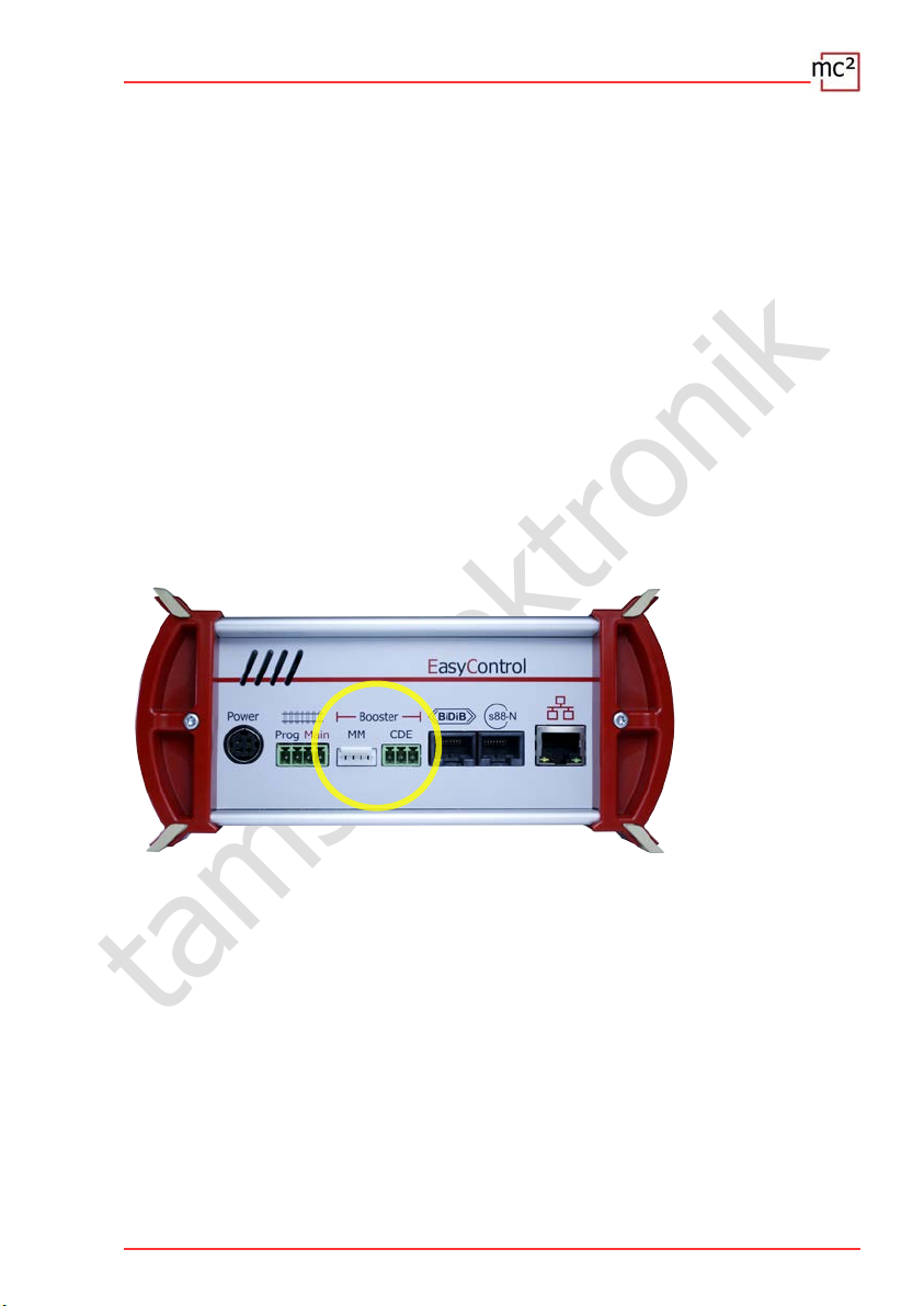
4.5. Connection of external boosters
If one booster is not sufficient to supply the layout or if the commands for vehicle and
accessory decoders are to be output separately ("driving and switching separately"), you can
connect additional external boosters.
MM: Märklin-compatible boosters
Connection: 5-pole, grid dimension 2.54 mm
CDE: DCC-compatible boosters
Connection: 3-pole, grid dimension 5.08 mm
(Connector plug included in delivery)
BiDiB: Boosters according to BiDiB
specification
Connection: RJ45
LocoNet-Boosters
Connection: RJ12
Note: The control of boosters and accessory decoders for
LocoNet as well as the forwarding of feedback signals from
LocoNet are not yet supported. (Status: 04/2021).
Simultaneous use of different booster interfaces
If you want to supply separate layouts (parts) or use separate boosters e.g. for driving and
switching, you can use all booster interfaces at the same time. However, you cannot supply
several booster sections of a layout mixed with different booster types (DCC-compliant,
Motorola-compatible, BiDiB, LocoNet).
Supply of several booster sections of a layout
Basically, if possible, identical boosters should be used to supply several booster sections of a
layout.
In combination with the integrated booster of the mc² you can use:
Booster B-4 (item no. 40-19407 or 40-19417): Connection to the DCC-compliant booster
output ("CDE") of the mc² or
BiDi-Booster (item no. 40-19407): Connection to the BiDiB interface of the mc². The
operating values of the BiDi booster are then reported back and can be used as a basis for
the booster management of a control software.
4.10 | Connections

tams elektronik
Note:
!
If you use other boosters than those previously mentioned to supply your system, you
should not use the integrated booster of the mc² to supply a booster section. Otherwise,
short-circuits and disturbances in data transmission may occur when crossing the separation
points between the sections.
Configuration
Before you start system operation, you must configure the boosters, i.e. set them to match
the nominal size of your system.
→ Section 5.5 in the manual
→ Menu item "System / Boosters"
4.6. Connection to the audio output
Info
The audio output of the mc² is technically correctly designated as a "line-out output". The lineout signal at the output has a high sound quality.
At present (as of 04/2021), the output is not yet supported by the software of the control unit.
With a later software version, it will be possible to store and retrieve background sounds in the
mc². It is also planned to call up situation-specific sounds together with the switching of
functions.
Later software versions will be available for free download from the Tams Elektronik website at
www.tams-online.de.
For the connection of
Active speakers (e.g. typical PC speakers)
Amplifiers in combination with passive loudspeakers
The connection is made via 2.5 mm stereo jack plugs.
Connections | 4.11

tams elektronik
4.12 | Connections

tams elektronik
5. Configuring the system (Submenu "System")
In the submenu "System" you make all the settings that are necessary to adjust your mc² for
operation with your layout. The explanations for the input fields open when you click on the
symbol .
5.1. System Info
In this menu item you can get an overview of the essential data of your digital central unit:
Hardware and software status of your mc²
Serial number, IP address and MAC address of your mc²
Flash and RAM allocation
Supply voltage
Temperature of the mc²
Track voltage: This value is set in the menu item "System / Boosters" according to the
nominal size of the layout.
Current / maximum current: The maximum current is set in the menu item "System /
Boosters". If the maximum current is exceeded, the integrated booster of the mc² is
automatically switched off.
Connected input devices: All input devices connected to the interfaces for EasyNet,
XpressNet, LocoNet or the CAN bus are displayed. Information on feedback devices
connected to the mc² can be queried in the menu items "Operation / Detectors" and
"Operation / BiDiB".
Info: Flash and RAM
"Flash" refers to the internal permanent memory of the mc², in which all data is stored that is
retained after switching off, e.g. the configuration, the locomotive database or audio files. An
occupancy of up to 90 % is not critical. It can be exceeded, for example, if a large number of
audio files are stored.
"RAM" refers to the internal working memory of the mc², in which all data generated during
operation are stored. An occupancy of up to 90 % is not critical. If this value is permanently
exceeded, there may be a defect in your mc². In this case, please contact the Technical
Hotline.
Info: Supply voltage
The supply voltage is 24 V in normal operation. If it is below 22 V, the power supply unit is
overloaded. This case occurs, for example, when the output current of the integrated booster
reaches the maximum of 6.5 A and at the same time many additional devices are connected to
the mc² which are supplied via the bus lines. In this case, you must reduce the current in the
booster circuit and/or the number of additional devices connected. In case of a permanent
overload, the power supply unit switches off automatically and switches on again after the
overload has been eliminated (hiccup mode).
Configuring the system (Submenu "System") | 5.1

tams elektronik
!
!
Info: Temperature
Heating of the central unit during operation is normal and harmless. Under permanent full
load, i.e. if the integrated booster supplies more than 6 A of current for a longer period of
time, the temperature can reach up to 75 °C.
Notice:
To prevent the mc² from overheating, you must ensure that a distance of at least 20 cm to
surrounding surfaces is maintained on the side surfaces and the top and rear of the mc².
If a high temperature is reached at low load, the mc² probably has a defect.
Notice:
If you notice overheating and suspect a defect in the mc² as the cause, disconnect the
central unit from the supply voltage immediately. Fire hazard! Send the mc² in for testing.
Saving and loading system settings
The configurations for the boosters, the protocols, the accessory decoders and the feedback
modules are saved in the file with the system settings. For the vehicle decoders, only the
standard format and purging are saved.
You can save and load the vehicle database ("locomotive list") separately in the menu item
"System / Vehicles".
Tip: When you have finished configuring your mc², you should save the system settings. You
can then load the settings again if the internal fixed memory of the mc² (the so-called "flash")
is damaged, e.g. in the event of a power failure.
5.2 | Configuring the system (Submenu "System")

tams elektronik
5.2. Vehicles
Management of the vehicles
Standard format
At delivery, the DCC format with 28 speed steps is set as standard, i.e. this protocol is applied
to the track by default. Vehicle decoders with the standard format can therefore be controlled
directly, vehicle decoders with different formats only if they have been created in the
locomotive list beforehand. The setting of the standard format is taken over as the default
setting in the locomotive list.
Standard
format
MM1/14
MM2/14
MM2/27A
MM2/27B
DCC/14
DCC/28
DCC/126
DCC/SDF
m3/126 mfx decoders that have been assigned an
Locomotive list
The database with your vehicles (in short "locomotive list") is a central part of your digital
control. Assigning names to your vehicles is not mandatory, but can be very helpful if the
decoder address has been forgotten or accidentally changed.
Function icons
Various icons are stored, which illustrate the numerous possible functions of vehicle decoders
(lights, couplers, smoke generators, sounds). Each icon is displayed in two versions, showing
the function in switched on or switched off state. You can replace the standard icons with your
own.
Vehicle decoders,
which can be controlled directly
all MM-decoders and mfx-decoders
If addresses >255 are selected, the mc²
automatically switches to DCC format, for
addresses >10,239 to m3 format.
all DCC decoders and mfx decoders that
support DCC
If addresses > 10,239 are selected, the
mc² automatically switches to the m3
format.
m3 address
Notes
As soon as the m3 signal is
present on the track (e.g. after
accidentally entering a locomotive
address >10,239), mfx vehicle
decoders react exclusively to m3
commands and no longer to MM
and/or DCC commands.
Assignment of the m3 address:
→ System / Vehicles / m3
→ Operation / Programming / m3
Configuring the system (Submenu "System") | 5.3

tams elektronik
Tractions
The control of locomotives in tractions is only possible if the same number of speed steps is
assigned to the decoders. Tractions with vehicle decoders with different data formats are
possible. Possible combinations:
DCC and Motorola decoders with 14 speed steps
DCC decoders with 28 speed steps and Motorola decoders with 27 speed steps
DCC decoders with 128 speed steps and mfx decoders with 126 speed steps
If you form tractions of locomotives with different driving directions, you can invert the driving
direction for one locomotive. In operation, this locomotive will then travel backwards (or vice
versa) when travelling forwards.
Tractions react together under all decoder addresses of the traction to driving commands and
the command to change direction. To switch the functions, the locomotive must be called up
under its respective address.
Further settings in the "Vehicles" menu item
Purging: You can specify that decoders that have not received any new driving or switching
commands within the set time (1 to 20 minutes) are removed from the refresh.
Lnet Dispatch: LocoNet hand controllers are used to control one specific vehicle. If you
have connected such a hand controller to the LNet interface of your mc², assign it "its"
decoder address here.
5.3. Accessories
Management of the accessory decoders
In this menu item you set how your accessory decoders are to be controlled by default:
Standard format
Minimum and maximum switching time
Number of repetitions of accessory decoder commands
You can also specify for which decoders exceptions to the standard format should apply.
Tip: The input field "Remarks" is intended for your notes on the accessory decoders. You can
enter free texts and save them in external files or load texts from external files.
5.4 | Configuring the system (Submenu "System")
tams elektronik
5.4. Protocol
Optimisation of the data transmission
With the default setting "normal", a safe and sufficiently fast transmission of digital data
between the mc², the decoders and the feedbacks is guaranteed for many installations.
In the help that opens after clicking on the symbol , you will find detailed explanations of
what is hidden behind the various terms. Basically, you should always set the default values if
you are not sure what deviating settings will do. In the following cases you should check the
settings and adjust them if necessary:
Use of Motorola decoders
Change the MM signal pause setting if
locomotives with Motorola I decoders do not react to driving and switching commands or
show a bad driving behaviour during driving operation
if function decoders for the Motorola format (e.g. in function models) do not react to digital
commands.
No use of RailCom
In this case, switch off RailCom and NOP. This switches off the RailCom gap and suppresses
the sending of NOP commands, thus increasing the speed of data transmission to the
decoders.
Control of mfx decoders
You must activate m3 (and assign an m3 address to the mfx decoders) to be able to control
them with the m3 format. Note: As soon as the m3 signal is present on the track (e.g. after
accidentally entering a locomotive address > 10,239), mfx vehicle decoders react exclusively
to m3 commands and no longer to MM and/or DCC commands.
If you prefer to control mfx decoders in DCC or MM format, you must deactivate m3.
Configuring the system (Submenu "System") | 5.5

tams elektronik
!
5.5. Boosters
Settings for the integrated and external boosters
With the setting of the nominal size, standard values for track voltage, maximum current,
short-circuit sensitivity and inrush time are preset, with which a safe operation on your layout
is guaranteed.
In the help that opens after clicking on the symbol , you will find explanations of what is
hidden behind the various terms. Basically, you should set the default values if you are not
sure what deviating settings will cause.
Setting options for the integrated booster
track voltage at the output
maximum current (cut-off current)
short-circuit sensitivity
inrush time
signal routing
The settings for the integrated booster also apply to boosters connected to the BiDiB and
LocoNet interfaces.
Notice:
Too high a track voltage and/or too high a cut-off current can cause damage to vehicles or
tracks. You are on the "safe side" if you set the nominal size of your layout in the menu item
"System / Boosters" and thus preset the usual values.
Setting options for the external boosters
Short-circuit sensitivity
Signal routing
The settings are made separately for DCC-compliant and Märklin-compatible boosters.
Info: Signal routing
By default, the commands for controlling the vehicle decoders are sent continuously via the
booster outputs of a digital central unit, the commands for the accessory decoders only when
required. For this purpose, the transmission of the vehicle decoder commands is briefly
interrupted, the accessory decoder commands are transmitted in the resulting gap.
In PC-controlled (larger) layouts, this type of data transmission can lead to problems, e.g. if
vehicle decoders receive stop commands too late and the locomotives overrun signals as a
result. To avoid this, in (larger) PC-controlled layouts the output of commands for vehicle and
accessory decoders is separated ("separate driving and switching").
With your mc² you can switch off the output of the accessory decoder commands separately
for the internal booster, the DCC-compliant and the Märklin-compatible booster output. The
setting for the internal booster also applies to boosters on the BiDiB and LocoNet interface. At
the booster output where the output of accessory decoder commands is switched off, only
vehicle decoder commands are then transmitted. For the output of the accessory decoder
commands then use another booster output.
5.6 | Configuring the system (Submenu "System")

tams elektronik
6. Operation with the mc²
6.1. Operating and display elements
The mc² has a STOP and GO button with which you can trigger essential functions directly on
the unit. To switch the track voltage on and off, you can alternatively click on the photo of the
mc² on the start page ("HOME") of the mc²-Toolbox.
The display on the front provides you with essential information about the operating status of
your mc². In addition, the RGB LEDs built into the housing change colour and thus visibly
indicate the operating status from afar.
6.1.1. STOP and GO buttons
Button Duration Function
GO short Switching on track voltage
STOP short Switching off track voltage St.
GO
GO,
GO,
GO, ...
STOP long
GO +
STOP
off*
GO
+ on*
off*
GO+STOP
+ on*
long
short,
short,
short, ...
long Reset ausführen rE
when
switching
on
when
switching
on
Reading out the IP address
The individual digits of the IP
address are retrieved by pressing
the "GO" key several times.
→ Section 2
Sending BiDiB-Identify for
the mc² (→ registration of
the mc² with the PC
control software)
Configuration incl. deleting
the locomotive list and
resetting to factory settings
Starting recovery software
→ section 7
Shown
in the display
0.0 or current power
consumption
IP|
12|3.4|56.|78|9.1|23
St.
Fr red
Dots flash alternately
Colour of the
RGB LEDs
green
red
red
blue
circulating
blue
flashing
+ white
swelling
violet
* off: Switching off the power supply
* on: Switching on the power supply while holding down the button(s)
Operation with the mc² | 6.1

tams elektronik
6.1.2. Display and RGB-LEDs
Shown
in the display
Colour of the
RGB LEDs
Meaning
0.0 to 6.5 green
current current consumption [A]
The track voltage is switched on.
St. red
Stop. The track voltage is switched off.
td
green
"Test Drive". In test mode you can control and
test vehicle and accessory decoders on the
programming track with the virtual control units
HandControl.prog. and FunctionControl.prog.
SH
red-violet
flashing
"Short Circuit" / short circuit during operation.
Troubleshooting → section 8.2
ot
yellow
"Overtemperature" / Overheating
Troubleshooting → Section 8.2
rE
blue
flashing
+ white
swelling
A reset is performed.
St.
blue
circulating
Stop / The track voltage is switched off.
If the STOP button was previously held longer, the command
for the BiDiB Identify for the mc² is sent.
PA
no colour
change
Pairing. Control software is loaded for the first
time on a connected PC or mobile terminal
IP|12|3.4|56.|78|9.1|23
no colour
change
IP address
The individual digits of the IP address are retrieved by pressing
the "GO" key several times. → Section 2
Pf
red
"Power failure". The input voltage is below 22
V. Disconnect the control unit from the supply
voltage immediately!
Troubleshooting → section 8.3
LP
red
"Low Power". The input voltage after switching
on is below 22 V. Disconnect the control unit
from the supply voltage immediately!
Troubleshooting → section 8.3
6.2 | Operation with the mc²

tams elektronik
Shown
in the display
Colour of the
RGB LEDs
Meaning
Fr
1...99 or ---
[ ]
E + digit
Dots flash
alternately
red
violet
circulating
blue
flashing
+ white
swelling
no colour
change
violet
The configuration is deleted and the mc² is
reset to the factory settings.
An update is being carried out. The digits
indicate the progress in %. During writing, the
progress display is interrupted.
The update is being processed and completed.
An internal error has occurred. Please make a
note of the digit(s) and contact the hotline.
The recovery software has been started.
→ Section 7
Operation with the mc² | 6.3

tams elektronik
6.2. Submenu "Operation"
In this submenu you can do all the things that occur during operation of you layout:
Controlling vehicle and accessory decoders
Reading out and programme decoders
Checking feedback modules
Reading out and displaying system messages
Setting the model time
The explanations of the input fields are opened when you click on the symbol .
6.2.1. Feedback
Overview of all connected feedback devices (s88, CAN, BiDiB and LocoNet)
Management and test of s88- and CAN- feedback modules
s88- (and CAN-) feedback modules
In this menu item you have to set how many s88 modules you have connected. Otherwise,
the feedback modules will not be taken into account when evaluating the s88 messages. A
module with 16 inputs is considered to be one. Modules with fewer inputs (e.g. 8) are
evaluated proportionally (e.g. as ½ module).
Note: CAN feedback modules are connected to the CAN interface, but their feedback signals
are forwarded via the s88 bus. They are therefore managed together with the s88 feedback
modules (→ menu item "Operation / Detectors").
You can also check the occupancy messages of the connected s88 and CAN feedback modules
and thus detect faulty messages. Differences between the display and the actual state of an
input indicate problems with the s88 bus, faults on the s88 module or on system parts
connected to the s88 module.
You can set the type of display
static or dynamic
for one or more modules
BiDiB feedback modules
The list is limited to the display of BiDiB nodes that meet the occupancy class requirements
defined in the BiDiB specification.
The display of all BiDiB nodes including the representation of their assignment to the levels as
well as the listing of their properties can be found in the menu item "Operation / BiDiB". There
you also have the option to trigger an Identify command and to perform a reset. → Section
6.2.4
LNet
The display of LocoNet detectors is not yet implemented. It will be implemented with one of
the next updates, which you can then download free of charge.
6.4 | Operation with the mc²

tams elektronik
6.2.2. Programming
Programming and reading vehicle and accessory decoders
Testing vehicle and accessory decoders
In this menu item you have access to all common programming types for vehicle and
accessory decoders:
Programming on the main track or programming track
Data formats: DCC, m3 and Motorola
With the virtual HandControl.prog on the side you can directly check the settings of decoders
on / at the programming track.
Note that main track programming (POM) and programming on the programming track
(PROG) and reading out the configuration variables (CVs) is not possible for all decoder types
and data formats.
Vehicle
decoders
DCC read out POM + PROG POM + PROG POM + PROG
program POM + PROG POM + PROG POM + PROG
MM read out PROG:
determine address
program PROG --- ---
m3 read out PROG:
determine UID
program
* Background info on programming accessory decoders
According to RailCommunity standard RCN-214, there are two ways of programming DCC
accessory decoders:
PROG:
assign addres
Accessory
decoders
Basic*
assign addres* ---
--- ---
--- ---
Accessory
decoder
Extended*
Basic is the most common type of programming. Unless otherwise stated in the accessory
decoder instructions, assume that "Basic" is the type of programming used for this decoder.
Extended is mainly used for programming signal decoders. Please check in the manual if
the decoder supports this type of programming.
With many Motorola accessory decoders it is possible to assign them their address by entering
a turnout address from a block of 4. To do this, they must be put into programming mode,
e.g. by attaching a jumper or pressing a button. With the mc² you can directly assign an
address to these Motorola accessory decoders when you connect them to the programming
track.
Operation with the mc² | 6.5

tams elektronik
HandControl.prog
The HandControl.prog and the FunctionControl.prog have almost the same functionality as the
standard versions of the virtual controllers and are especially used for testing decoder
settings. However, in test mode (display "td" in the display of the mc²) you can only control
vehicle and accessory decoders on / at the programming track.
HandControl.vi → section 6.3.1
FunctionControl.vi → section 6.3.2
The following functions differ from the standard version of the virtual HandControl:
Change to FunctionControl.prog
Change of the interface for switching accessory decoders at the programming track
Change to HandControl.vi (the standard version of the virtual HandControl)
Testing accessory decoders
To select the turnout
address, enter the
address via the
number fields.
Afterwards you can
switch between the
two turnout positions
with the buttons
and
6.6 | Operation with the mc²
Turnout
"straight ahed"
Turnout
adress
Turnout
position
Turnout
"branch"

tams elektronik
6.2.3. Messages
Read out and display system messages
The messages help to check the function of the connected components and to find the causes
of malfunctions.
RailCom messages
You can display all messages or limit the type of messages to be displayed by:
Decoder address
Decoder type
Type of message
Messages from the BiDi bus
The display of BiDiB messages is currently not yet implemented (as of April 2021).
System messages
These help to find causes of malfunctions of your digital system. Tip: Before contacting the
Technical Hotline about problems with your digital control, connect your mc² to a PC or tablet.
The hotline staff may ask you to read out certain types of messages.
6.2.4. BiDiB
Display of all connected BiDiB nodes, their assignment to the levels and their properties
Identify and Reset
The list shows all connected BiDiB nodes and their assignment to the levels. According to the
BiDiB specification, the mc² is a node and fulfils the tasks of a BiDiB interface and a track
output device. The integrated booster also reports its data via the BiDi bus. The mc² is
therefore displayed as a BiDiB node in the top level - regardless of whether other BiDiB
components are present.
The properties of the BiDiB nodes are listed in the info field:
the address
the manufacturer
the type designation
the name and
the features
After right-clicking on the name of a node, a window opens and you can send an Identify
command or reset the node.
Operation with the mc² | 6.7

tams elektronik
6.2.5. Control
Calling the virtual HandControl.vi
The HandControl.vi is similar to the "real" HandControl.2. You can select and control vehicle
decoders directly with it. From the HandControl.vi you can also reach the other virtual control
units
FunctionControl.vi for controlling a vehicle decoder
DriveControl.vi to control up to four vehicle decoders simultaneously
SwitchControl.vi for switching accessory decoders
For the functionality and operation of the virtual control units → section 6.3
6.2.6. Model time
Controlling the layout according to timetable
For the control of your layout according to a timetable this menu item allows you
to start and stop the model time
to define the start time
to define teh time factor: Depending on the setting, the model time runs up to 60 times
faster than the real time.
to select the design
Alternatively, you can set the model time in your PC control software.
Tip: Use a smartphone or tablet that you position in a place visible from all areas of your
layout to display the model time. You can choose between four different designs for the
display of the model time.
6.8 | Operation with the mc²

tams elektronik
6.3. Virtual control devices
The virtual control devices enable e.g. the use of tablet(s) or smartphone(s) as external
control units or tests during configuration or programming on the PC screen. Depending on
the operating situation, you can choose between four different user interfaces and switch back
and forth:
HandControl.vi with a user interface based on the HandControl.2
FunctionControl.vi for controlling one vehicle decoder
DriveControl.vi for simultaneous control of up to four vehicle decoders
SwitchControl.vi for switching accessory decoders
6.3.1. HandControl.vi
Calling up the vehicle address
Proceed as follows to select a locomotive or function decoder for driving and/or switching:
Click on the locomotive symbol .
Enter the decoder address by clicking on the number fields.
Confirm the entry with .
The "Display" shows the address, the data format, the vehicle name, the current speed step
and driving direction as well as the switched-on functions.
To delete an incorrect entry, click on . .
Driving a locomotive
For the locomotive shown in the "display", you can
change the speed level with the slider and
change the direction of travel by clicking on the direction switch.
The current power consumption is shown in the bar below the display.
Switching functions
For the selected vehicle, you can switch the functions F0 to F9 on and off directly by clicking
on the number fields. To switch functions up to F32, you must switch to FunctionControl.vi by
clicking on . All switched-on functions up to F20 are shown in the "Display".
Switching to other virtual control units or to the menu
You can switch directly to the other virtual control units or back to the menu.
FunctionControl.vi to control the selected vehicle
SwitchControl.vi to switch accessory decoders
DriveControl.vi to control up to four vehicles
Menu of the mc²-Toolbox
Operation with the mc² | 6.9

tams elektronik
6.10 | Operation with the mc²
Current direction
> forwards
< backwards
Current
speed level
Digital
format
Vehicle
name
Delete
entry
Change to
FunctionControl.vi
Speed
controller
Change to
SwitchControl.vi
Actual current
Back to menu
Decoder
address
Confirm
infput
Function keys
(F)1, 2, 3…9, 0
Direction
change-over
switch
Switched on
functions
0, 5, 10, 19, 20
Select locomotive
Change to
DriveControl.vi

tams elektronik
6.3.2. FunctionControl.vi
With the FunctionControl.vi you can control the vehicle decoder that you have previously
called up with the help of the HandControl.vi. While you can only switch the functions F0 to F9
on and off with the HandControl.vi, the FunctionControl.vi allows you to switch the functions
F0 to F32. If you have assigned icons to the functions, these are displayed instead of the
function numbers.
You can switch between displaying the speed controller on the left or right side of the user
interface by clicking on the field .
From FunctionControl.vi you can switch directly to SwitchControl.vi to switch accessory
decoders or go back to HandControl.vi.
Decoder
address
Vehicle
name
Digital
format
Current
speed level
Function keys
(F)1, 2, 3…9, 0
Switched on
functions
0, 5, 10, 19, 20
Full screen mode on/off
Change to
SwitchControl.vi
Change to
HandControl.vi
Direction
change-over
switch
Speed
controller
Speed controller
to the left side
Operation with the mc² | 6.11

tams elektronik
6.3.3. DriveControl.vi
Select up to four vehicle decoders that you want to control. To do this, enter the addresses
directly in the input fields or click the arrow keys to increase or decrease the set address by
1 each.
You can change the speed level for the selected vehicle decoders using the sliders, change the
direction of travel and switch the F0 function on and off.
You can go from DriveControl.vi directly back to HandControl.vi.
6.12 | Operation with the mc²
Speed
controller
Change to
HandControl.vi
Full screen mode on/off
Direction change-
over switch
Function
key F0
Decoder
adresses

tams elektronik
6.3.4. SwitchControl.vi
The SwitchControl.vi allows you to switch accessory decoders up to turnout address 2048. To
switch to the next 16-number block, click on or . To skip several blocks of 16
numbers, use the double arrows.
You can switch between displaying the speed controller on the left or right side of the user
interface by clicking on the field ..
From FunctionControl.vi you can go directly to FunctionControl.vi to control the last vehicle
called up or go back to HandControl.vi.
Decoder
address
Vehicle
name
Digital
format
Current
speed level
Function
key F0
Full screen mode on/off
Change to
FunctionControl.vi
Change to
HandControl.vi
Direction
change-over
switch
Turnout keys
1 … 2.048
Speed
controller
Change
Speed
controller
to the
right side
Operation with the mc² | 6.13
block of 16

tams elektronik
6.14 | Operation with the mc²

tams elektronik
7. Updates
The mc² central unit is a mature product corresponding to the current state of the art and has
been intensively tested. However, the large number of connection options for various digital
devices and the resulting huge number of possible combinations, as well as the variety of
system concepts and possibilities for system implementation, make it impossible to test all
conceivable constellations in advance. Despite all tests, we therefore cannot exclude the
possibility of problems occurring during operation with your system and your digital devices.
We make every effort to correct problems caused by errors in the firmware and/or the web
interface of your mc² as quickly as possible.
Future developments in the field of digital control of model railways - both in terms of
standardisation and digital devices - will require further developments of the firmware and/or
the web interface of your mc². In addition, there will be additional functions that we develop
for the mc² central unit.
Free updates for the mc²
You benefit from the further development of the mc² by installing updates for the firmware
and/or the mc²-Toolbox. Updates are free of charge for you. The latest version of the
firmware and the web interface are displayed in the menu item "Update" of the mc²-Toolbox.
You can check the current version of your mc² in the menu item "System Info".
How to update your mc² is described in the direct help in the menu item "Update".
Updates for other EasyControl devices
Under the menu item "Update" of the mc²-Toolbox, you can also carry out updates for further
digital devices for the EasyControl digital system. The prerequisite is that the device is
connected to your mc² via the EasyNet interface. How to carry out updates for these devices
is described in the direct help in the menu item "Update".
Recovery software
For mostly incomprehensible reasons, an update may fail. If your mc² then no longer responds
to renewed attempts to start an update, proceed as follows:
Download the recovery software (mc2recovery.exe) from the download area of our
homepage (www.tams-online.de) to your PC.
Install the software mc2recovery.exe on your PC and start it.
Enter the data path under which you have saved the current firmware for the mc².
Switch off the supply voltage of the mc².
Keep the "STOP" and "GO" keys pressed while switching the supply voltage back on. A dot
flashes alternately in the two segments of the display.
Keep the "STOP" and "GO" buttons pressed until the update starts. Release the buttons as
soon as the display shows the progress of the update (in %).
Updates | 7.1

tams elektronik
7.2 | Updates

tams elektronik
8. Checklist for troubleshooting
When delivered, your mc² has the password "Tams". If you have changed the password and
then forgotten it, you can display it on the web developer console of your browser. Click on
set (password) after opening, the password will then be displayed in the console. On the
Internet you can find instructions on how to get to the web developer console of your
browser.
8.1. Heat generation
Heating of the central unit and the power supply unit during operation is normal and harmless.
Under continuous full load, i.e. when the integrated booster supplies more than 6 A of current
for a longer period of time, the temperature can reach up to 75 °C. If a high temperature is
reached at low load, the mc² probably has a defect.
Warning:
!
If you notice severe overheating on the mc² and/or the power supply unit, disconnect the
central unit and the power supply unit from the supply voltage immediately. Fire hazard!
Send in the mc² and the power supply unit for testing.
8.2. Automatic safety shutdown
The mc² switches off the track voltage and indicates a short circuit.
Indication in the display: "SH" | RGB-LEDs: red and violet alternately
Possible cause: short circuit on the rails à Eliminate the short circuit.
Possible cause: exceeding the maximum permissible current in a booster circuit à Check
whether the maximum current for the booster(s) is set correctly (menu item "System /
Boosters"). à If the maximum current was set correctly, you must reduce the current
consumption in the booster circuit.
Possible cause: exceeding the maximum permissible total current (= 6.67 A). The reason is
usually a permanently high current consumption in the booster circuit of the integrated
booster with a simultaneously large number of external digital devices at the CAN, LocoNet,
EasyNet and/or BiDiB interface. à Reduce the current consumption. Supply the external
digital devices via an external power supply if possible.
The mc² switches off the track voltage and indicates overheating.
Indication in the display: "ot" | RGB-LEDs: yellow
Possible cause: overheating à Check whether the mc² has sufficient distance to
surrounding surfaces and/or is exposed to direct sunlight. Ensure unhindered air exchange.
Possible cause: Permanently high current consumption just below the maximum permissible
total current (= 6.67 A). The reason is usually a permanently high current consumption in
the booster circuit of the integrated booster with a simultaneous large number of external
digital devices at the CAN, LocoNet, EasyNet and/or BiDiB interface. à Reduce the current
consumption. If possible, supply the external digital devices via an external power supply.
Checklist for troubleshooting | 8.1

tams elektronik
!
The power supply unit switches off and then on again after a while.
Possible cause: overload à Reduce the number of connected additional devices and/or the
power consumption in the booster circuit of the integrated booster. As soon as the overload
is eliminated, the power supply unit is automatically switched on again.
Possible cause: Overvoltage à As soon as the input voltage of the power supply unit is
within the permissible range again, it is automatically switched on again.
Possible cause: Overheating à Check whether the power supply unit has sufficient distance
to surrounding surfaces and/or is exposed to direct sunlight. Ensure an unhindered
exchange of air. As soon as the power supply unit has cooled down, it is automatically
switched on again.
8.3. Problems with the power supply
The input voltage is less than 22 V.
Indication on the display: "Pf" or "LP" | RGB LEDs: red
Warning:
If the display shows "Pf" (Power Fail) or "LP" (Low Power), disconnect the central unit from
the power supply immediately. There are incalculable risks in continuing to operate the
system!
Possible cause: Overload of the power supply unit. The reason is usually a permanently
high current consumption in the booster circuit of the integrated booster with a
simultaneous large number of external digital devices at the CAN, LocoNet, EasyNet and/or
BiDiB interface. à Reduce the current consumption. If possible, supply the external digital
devices via an external power supply.
Possible cause: defect at the power supply unit. à Check the supply voltage of the mc² in
the menu item "System / Info". If it is below 22 V despite low current consumption in the
booster circuit of the integrated booster and a low number of connected external digital
devices, the power supply unit is probably defective. Send it in for checking.
8.4. Problems with external input devices
The decoders do not respond to digital commands entered at a digital central unit on the
Sniffer.
Possible cause: The central unit on the Sniffer is not set to DCC or Motorola as the format
for track output. However, the mc² cannot evaluate digital commands in different formats.
à Change the setting at the connected command station.
A locomotive with mfx decoder cannot be controlled with an input device connected to the
CAN interface of the mc².
Possible cause: The mc² cannot control mfx decoders directly. à You must first assign an
address for the m3 format to the decoder (menu item "Operation / Programming").
8.2 | Checklist for troubleshooting

tams elektronik
8.5. Problems when programming and controlling vehicles
A locomotive does not react to driving and switching commands, although you have entered
the correct locomotive address.
Possible cause: A wrong data format is assigned to the locomotive address. à Change the
data format.
Vehicles with DCC decoder
When programming a DCC decoder the mc² displays an error message.
Possible cause: You have selected a programming type that is not supported by the
decoder. à Check with the instructions for the decoder which programming types it is
designed for.
A locomotive with DCC decoder is already running at very high speed at speed level 1.
Possible cause: The number of speed steps "128" is assigned to the locomotive address,
but the locomotive decoder only supports 14 or 28 speed steps. à Change the number of
speed steps.
On a locomotive with DCC decoder the light cannot be switched and / or the light flickers
when switching up the speed steps.
Possible cause: The setting of the number of speed steps on the decoder and on the mc²
do not match. à Change the number of speed steps on the decoder or on the mc².
Vehicles with Motorola decoder
When switching up the speed steps for a locomotive with Motorola decoder, the speed is
actually changed only at every second speed step.
Possible cause: The number of speed steps "27a" or "27b" is assigned to the locomotive
decoder, but the locomotive decoder supports only 14 speed steps. à Change the number
of speed steps.
During operation locomotives with Motorola I decoders cause problems: They do not react to
driving and switching commands or have a bad driving behaviour.
Possible cause: The length of the signal pause is set incorrectly. à Change the pause time.
During operation, function models with Motorola decoders do not react correctly to digital
commands.
Possible cause: The length of the signal pause is set incorrectly. à Change the pause time.
Checklist for troubleshooting | 8.3

tams elektronik
Vehicles with mfx decoder
Vehicles with mfx decoder cannot be controlled in Motorola or DCC format, although these
formats are entered for them in the locomotive list.
Possible cause: An m3 address was called up (e.g. by accidentally entering a vehicle
decoder address >10,239). à Perform a reset on the mc². Should an m3 address be active
on one of the virtual controllers or an EasyControl device, deactivate it before performing
the reset. If you generally do not want to control your mfx locomotives in the m3 format,
you can deactivate this format in the menu item "System / Protocol".
Tractions
The locomotives of a double traction run in opposite directions.
Possible cause: When forming the double traction you did not invert the direction of travel
for one locomotive. à Form the double traction again.
8.6. Problems when switching points and other accessories
The turnouts or the accessories cannot be switched.
Possible cause: The data format for the accessory decoder is set incorrectly. à Change the
data format.
Possible cause: Accessory decoders for the Motorola format are connected with the wrong
polarity. à Check the connections and change the polarity at the track or decoder
connection if necessary.
8.7. Problems with s88 modules
When testing an s88 module all inputs are shown as occupied although they are (partly) free.
Possible cause: The connection to the 6-pole plug of a feedback module is wrongly
polarised. à Check whether the 6-pole socket has been plugged in the right way round. If
the connection is made via an s88-N adapter, check whether you have used the correct
adapter or connected the adapter the right way round.
You cannot test all s88 modules although they are connected correctly.
Possible cause: The number of s88 modules is set incorrectly. à Check and change the
number of s88 modules. Note: Arithmetically, one s88 feedback has 16 contacts each.
Feedback units with 8 contacts therefore only count as ½ feedback unit.
8.4 | Checklist for troubleshooting

tams elektronik
8.8. Problems with the software update
The firmware update for the mc² fails.
Possible cause: An attempt was made to load an incorrect file. à Check whether you had
selected the correct file and start the update again.
If the firmware update is still not possible after several attempts or can no longer be
started, you must load the recovery software and run the programme. → Section 7
During the update of a connected EasyNet device, the progress bar jumps back to the
beginning (several times).
This is not an error. The update programme continuously checks whether the data transfer
is correct. If this is not the case, the programme restarts the update for security reasons.
8.9. Technical hotline
Under the menu item "Contact" in the footer of the mc²-Toolbox you will find all information
about our technical hotline and a contact form. The data can also be found on our homepage
at www.tams-online.de.
8.10. Repairs
You can send us a defective mc² and/or a defective power supply unit for testing and repair.
You will find the address under the menu item "Contact" in the footer of the mc²-Toolbox, on
the back of the mc² guide and on the last page of this manual.
In the event of a warranty claim, the repair is free of charge for you. In the case of damage
that is not covered by the warranty, we charge a maximum of 50 % of the new price of the
central unit for the repair in accordance with the valid price list for end users. We reserve the
right to refuse to repair a central unit if this is technically impossible or uneconomical.
Please do not send us repair shipments freight collect. In the event of a warranty claim, we
will reimburse you for regular shipping costs. In the case of repairs that are not covered by the
warranty, you will bear the costs for return shipment.
Checklist for troubleshooting | 8.5

tams elektronik
8.6 | Checklist for troubleshooting

tams elektronik
9. Technical data
9.1. Digital control unit mc²
Digital protocols
Data formats Motorola-I and -II
DCC (according to NMRA and RCN standard)
m3 (to control mfx decoders)
Vehicle decoder addresses Motorola: 255 (1 – 255)
DCC: 10,239 (1 – 10,239)
m3: 16,384 (1 – 16,384)
Speed levels Motorola: 14 or 27 (a or b)
DCC: 14, 28 or 128
m3: 126
Functions Motorola: function, f1 to f4
DCC: f0 to f31 or f32,768
m3: f0, f1 to f31
Accessory decoder addresses Motorola: 1,020 (1 – 1,020)
DCC: 2,040 (1 – 2,040)
m3: ---
Feedback formats RailCom
Interfaces
For the connection of
external input devices
For the connection of
external feedback modules
Computer interface LAN (RJ45) / TCP
Märklin-Can-Bus (10-pole)
LocoNet (RJ12)
EasyNet (RJ45)
XpressNet (RJ12)
Sniffer (2-pole, grid dimension 2,54 mm)
Märklin-Can-Bus (10-pole)
LocoNet (RJ12)
s88-N (RJ4
Number of s88 modules:
52 s88 or s88-compatible modules (832 contacts)
BiDiB (RJ45)
max. number of BiDiB nodes: 31 in one level
Protocols: BiDiB and p50x
Technical data | 9.1

tams elektronik
Audio interface Line-out output for connecting active speakers or amplifiers
(2.5 mm stereo jack plug)
Interfaces for external
boosters
Märklin-compatible
DCC compliant
BiDiB
LocoNet
Track outputs Main track
Programming track
Electrical properties
Power supply 24 volts direct current
Note: Only the power supply unit included in the scope of delivery is permitted
as power supply for the mc² including integrated booster!
Maximum total current 6.67 A
Maximum current for
external digital devices
1,200 mA
Note: The specification refers to all digital devices on the CAN, LocoNet,
EasyNet, XpressNet and BiDiB interfaces that are supplied with power via the
respective bus line.
Current consumption
(without consumer)
approx. 150 mA
Integrated Booster
Output voltage 8 to 22 volts digital voltage (regulated)
adjustable in 1 V steps
Maximum output current 1 to 6.5 A
adjustable in 0.5 A steps
Power consumption max. 143 Watt
Digital formats DCC, Motorola, m3
Feedback format RailCom (RailCom cutout can be switched off)
integrated global RailCom detector
Output signal symmetrical
Safety automatic switch-off in case of overload
("short-circuit shutdown")
Short-circuit sensitivity: 10 - 2,000 ms (adjustable)
9.2 | Technical data

tams elektronik
Predection
Predection clas IP 20
Meaning: Predected against solid foreign bodies with a diameter ≥ 12.5 mm
and access with a finger. No predection against water.
Overload 100 ~ 110% of the rated output power
Predection: Switching off the voltage at the track output
Overtemperature Switching off the voltage at the track output
Environment
For use in closed rooms
Note: To allow unhindered air exchange and to predect the unit from
overheating, a distance of at least 20 cm must be maintained between the side,
top and rear surfaces and surrounding surfaces.
Ambient temperature during
operation
Permissible relative humidity
during operation
Ambient temperature during
storage
Permissible relative humidity
during storage
Other features
Dimensions (approx.) 175 x 154 x 82 mm
Weight (approx.) 831 g
0 ~ + 60 °C
10 ~ 85% (non-condensing)
- 10 ~ + 80 °C
10 ~ 85% (non-condensing)
Technical data | 9.3

tams elektronik
9.2. Power supply unit
Manufacturer MEAN WELL ENTERPRISE Co. Ltd.
Type designation GSM160B24-R7B
Output
Output voltage 24 VDC
Rated current 6.67 A
Output current 0 – 6.67 A
Rated powerNennleistung max. 160 watts
Input
Input voltage 80 ~ 264 VAC or 113 ~ 370 VDC
Frequency range 47 ~ 63Hz
Input current 90A / 115VAC or 110A / 230VAC
Predection
Predection type
IP 22
Meaning: Predected against solid foreign bodies with diameter ≥ 12.5 mm and
access with a finger. Predection against falling dripping water when the
enclosure is tilted up to 15°.
Predection class (= Predection class 2)
Overload
105 ~ 150% of the rated output power
Predection mode: Hiccup mode, i.e. automatic recovery
after elimination of fault condition
Overvoltage
105 ~ 135% of the rated output voltage
Predection mode: Switching off the output voltage,
switching on again for recovery
Overtemperature
Predection mode: Switching off the output voltage,
switching on again for recovery
9.4 | Technical data

tams elektronik
Environment
For use in closed rooms
Note: To allow unhindered air exchange and to predect the unit from
overheating, a distance of at least 20 cm must be maintained between the side
surfaces, the top surfaces and the rear surfaces to ambient surfaces.
Ambient temperature during
operation
Permissible relative humidity
during operation
Ambient temperature during
storage
Permissible relative
humidityduring storage
Connections
Unit connection Power supply connector 4-pole with snap lock, R7B series
Mains connection Mains cable socket 2-pole, IEC 320-C8
Miscellaneous
Dimensions (approx.)
Weight (approx.)
Length of connection cable
-30 ~ + 70 °C
20 ~ 90% (non-condensing)
- 40 ~ + 85 °C
10 ~ 95% (non-condensing)
175 x 72 x 35 mm
660 g
1,200 mm + 50 mm
Technical data | 9.5

tams elektronik
9.6 | Technical data

tams elektronik
10. Warranty, EC Conformity & WEEE
10.1. Warranty Statement
We voluntarily grant a 2-year warranty for this product from the date of purchase by the
original customer, but for a maximum of 3 years after the end of series production of the
product. The first customer is the consumer who first purchased the product from us, a dealer
or another natural or legal person who resells or installs the product in the course of his or her
independent professional activity. The warranty exists in addition to the statutory warranty
claims to which the consumer is entitled against the seller.
The scope of the guarantee includes the free repair of defects which can be proven to be due
to material processed by us which is not in perfect condition or to manufacturing defects. In
the case of kits, we guarantee the completeness and perfect condition of the components, as
well as a function of the components in accordance with the characteristic values in uninstalled
condition. We guarantee compliance with the technical data if the kit is assembled in
accordance with the instructions and the finished circuit is installed and commissioned and
operated in the prescribed manner.
We reserve the right to repair, rectify, replace or refund the purchase price. Further claims are
excluded. Claims for compensation for consequential damage or from product liability exist
only in accordance with the statutory provisions.
A prerequisite for the effectiveness of this guarantee is compliance with the operating
instructions. Furthermore, the warranty claim expires in the following cases:
in the event of unauthorised modification of the circuit,
in the event of attempted repairs to the finished component or finished unit,
in the event of damage caused by the intervention of third parties,
incorrect operation or damage due to negligent handling or misuse.
Warranty, EC Conformity & WEEE | 10.1

tams elektronik
10.2. EC Declaration of Conformity
This product fulfils the requirements of the following EU directives and therefore
bears the CE marking.
2001/95/EU Product Safety Directive
2015/863/EU on the restriction of the use of certain hazardous substances in electrical and
electronic equipment (RoHS)
2014/30/EU on electromagnetic compatibility (EMC Directive). Underlying standards:
DIN-EN 55014-1 and 55014-2: Electromagnetic compatibility - Requirements for household
appliances, electric tools and similar electrical appliances. Part 1: Emitted interference, Part 2:
Immunity to interference
To maintain electromagnetic compatibility during operation, observe the following measures:
Only connect the power supply unit to a professionally installed and fused socket.
Do not make any changes to the original components and follow the instructions in this
manual exactly.
Only use original spare parts for repair work.
10.3. Declarations on the WEEE Directive
This product complies with the requirements of the EU Directive 2012/19/EC on
Waste Electrical and Electronic Equipment (WEEE). .
Do not dispose of this product in (unsorted) municipal waste, but recycle it.
10.2 | Warranty, EC Conformity & WEEE

tams elektronik
Appendix A : Organisations, Manufacturers, Products
The mc² has interfaces for connecting digital devices from various manufacturers, based on
data transfer protocols from different manufacturers and organisations. In the list you will find
the contact details as well as a selection of products that you can use together with your mc².
Manufacturer
Organisation
Address Internet Protocols
Products (selection)
Working group
BiDiB
Wolfgang Kufer,
Lodronstr. 9
84453 Mühldorf
Germany
http://www.bidib.org BiDiB-spezification
Digitrax, Inc 2443 Transmitter Rd
Panama City, FL
32404-3157 USA
www.digitrax.com LocoNet
Gebr. Märklin &
Cie. GmbH
Stuttgarter Str. 55-57
73033 Göppingen
Germany
www.maerklin.de Märklin CAN-Bus
Mobile Station (2/3)
Central Station (2/3)
Lenz
Elektronik
GmbH
Vogelsang 14
35398 Gießen
Germany
www.lenz-elektronik.de XpressNet
Handheld controllers
LH100 and LH101
PIKO
Spielwaren
GmbH
Lutherstraße 30
96515 Sonneberg
Germany
www.piko.de SmartControl light
RailCommunity
Verband der
Hersteller Digitaler
Modellbahn-produkte
e.V.
www.railcommunity.de RailCommunity-
Standards (RCN)
Roco
Modelleisenbahn
GmbH
Plainbachstraße 4
5101 Bergheim
Austria
www.roco.cc Lokmaus
Multimaus
Tams
Elektronik
GmbH
Fuhrberger Str. 4
30625 Hannover
Germany
www.tams-online.de EasyNet
HandControl
LokControl
MasterControl
mControl
Booster B-4
BiDi-Booster
BiDi-Power
Uhlenbrock
Elektronik
GmbH
Mercatorstrasse 6
46244 Bottrop
Germany
www.uhlenbrock.de Handheld controllers
FRED and Daisy 2
Intellibox
Appendix A.1

tams elektronik

tams elektronik
Appendix B : Changes and additions
The list gives you an overview of changes or additions to the mc²-Toolbox software and new
or changed pages of the manual.
Manual
Version
mc²-Toolbox
Version
Changes / Additions Replacement
pages
1.00
© 04/2021
1.00
1.01
© 05/2021
1.10 Manual:
Editorial changes
mc² toolbox:
Elimination of problems with setting the
default format for vehicles with some
browsers.
Addition of the languages English, French
and Dutch
---
Appendix B.1

tams elektronik

tams elektronik

tams elektronik
n
n
n
n
Weitere Informationen und Tipps:
More information and tips:
Plus d'informations et de conseils :
Meer informatie en tips:
n
n
http://www.tams-online.de
n
n
n
n
Garantie und Service:
Warranty and service:
Garantie et service :
Garantie en service:
n
n
Tams Elektronik GmbH
n
Fuhrberger Straße 4
DE-30625 Hannover
n
fon: +49 (0)511 / 55 60 60
fax: +49 (0)511 / 55 61 61
n
e-mail: modellbahn@tams-online.de
n
n
 Loading...