

Page 1
tams elektronik
Manual
LED Control
LED Control Basic
LED constant current source
Item no. 53-00100
FB-11 | FB-12 | FB-13
Cab lighting
Item no. 53-00110 | 53-00120 | 53-00130
ZSB-2
Train rear lighting
Item no. 53-00180
tams elektronik
n n n
Page 2

tams elektronik
English LED-Control
Table of contents
1. Getting started............................................................................3
2. Safety instructions.......................................................................5
3. Safe and correct soldering...........................................................8
4. Operation overview.....................................................................9
5. Technical specifications..............................................................11
6. Connections..............................................................................12
7. Check list for troubleshooting.....................................................17
8. Guarantee bond........................................................................18
9. Declaration of conformity...........................................................19
10. Declarations conforming to the WEEE directive...........................19
© 12/2015 Tams Elektronik GmbH
All rights reserved. No part of this publication may be reproduced or
transmitted in any form or by any means, electronic or mechanical,
including photocopying, without prior permission in writing from Tams
Elektronik GmbH.
Subject to technical modification.
Page 2
Page 3

tams elektronik
LED-Control English
1. Getting started
This manual applies to the following lighting modules, so for:
LED Control
Basic
,
train rear lighting ZSB-2,
driver´s cab lighting FB-11, FB-12 and FB-13.
Provided there are no other details given for particular sections, the
information given applies to all modules.
How to use this manual
This manual gives step-by-step instructions for safe and correct fitting and
connecting of the modules, and operation. Before you start, we advise you
to read the whole manual, particularly the chapter on safety instructions
and the checklist for trouble shooting. You will then know where to take
care and how to prevent mistakes which take a lot of effort to correct.
Keep this manual safely so that you can solve problems in the future. If
you pass the module on to another person, please pass on the manual
with it.
Intended use
The modules are designed for mounting and use in model railroad
vehicles driven in analogue or digital controlled layouts. Any other use
is inappropriate and invalidates any guarantees.
The modules should not be mounted by children under the age of 14.
Reading, understanding and following the instructions in this manual
are mandatory for the user.
Page 3
Page 4
tams elektronik
English LED-Control
Checking the package contents
PCBs Additional
components,
characteristics
CD (containing the
manual and further
information)
LED Control
Basic
2 --- 1
ZSB-2 2 2 LEDs shaped like
train rear lanterns,
nominal size TT - H0
1
FB-11 2 equipped with a
yellow LED
1
FB-12 2 equipped with a
pure white LED
1
FB-13 2 equipped with a
warm white LED
1
Required materials
For mounting and connecting the module you need:
an electronic soldering iron (max. 30 Watt) or a regulated soldering
iron with a fine tip and a soldering iron stand,
a tip-cleaning sponge,
a heat-resistant mat,
a small side cutter and wire stripper,
as necessary a pair of tweezers and long nose pliers,
thin connecting wire.
With LED Control
Basic
: LEDs for the vehicle´s lighting.
If required: a bridging capacitor (> 100 µF) with a voltage sustaining
capability of
> 16 V (when connected to a power supply < 18 V) or
> 25 V (when connected to a power supply > 18 V).
Page 4
Page 5

tams elektronik
LED-Control English
2. Safety instructions
Mechanical hazards
Cut wires can have sharp ends and can cause serious injuries. Watch
out for sharp edges when you pick up the PCB.
Visibly damaged parts can cause unpredictable danger. Do not use
damaged parts: recycle and replace them with new ones.
Electrical hazards
Touching powered, live components,
touching conducting components which are live due to malfunction,
short circuits and connecting the circuit to another voltage than
specified,
impermissibly high humidity and condensation build up
can cause serious injury due to electrical shock. Take the following
precautions to prevent this danger:
Never perform wiring on a powered module.
Assembling and mounting the kit should only be done in closed,
clean, dry rooms. Beware of humidity.
Only use low power for this module as described in this manual and
only use certified transformers.
Connect transformers and soldering irons only in approved mains
sockets installed by an authorised electrician.
Observe cable diameter requirements.
After condensation build up, allow a minimum of 2 hours for
dispersion.
Use only original spare parts if you have to repair the kit or the
ready-built module.
Page 5
Page 6

tams elektronik
English LED-Control
Fire risk
Touching flammable material with a hot soldering iron can cause fire,
which can result in injury or death through burns or suffocation.
Connect your soldering iron or soldering station only when actually
needed. Always keep the soldering iron away from inflammable
materials. Use a suitable soldering iron stand. Never leave a hot
soldering iron or station unattended.
Thermal danger
A hot soldering iron or liquid solder accidentally touching your skin can
cause skin burns. As a precaution:
use a heat-resistant mat during soldering,
always put the hot soldering iron in the soldering iron stand,
point the soldering iron tip carefully when soldering, and
remove liquid solder with a thick wet rag or wet sponge from the
soldering tip.
Dangerous environments
A working area that is too small or cramped is unsuitable and can cause
accidents, fires and injury. Prevent this by working in a clean, dry room
with enough freedom of movement.
Page 6
Page 7

tams elektronik
!
LED-Control English
Other dangers
Children can cause any of the accidents mentioned above because they
are inattentive and not responsible enough. Children under the age of
14 should not be allowed to work with this kit or the ready-built
module.
Caution: Little children can swallow small components with
sharp edges, with fatal results! Do not allow components to reach
small children.
In schools, training centres, clubs and workshops, assembly must be
supervised by qualified personnel.
In industrial institutions, health and safety regulations applying to
electronic work must be adhered to.
Page 7
Page 8

tams elektronik
!
English LED-Control
3. Safe and correct soldering
Caution: Incorrect soldering can cause dangers through fires
and heat. Avoid these dangers by reading and following the directions
given in the chapter Safety instructions.
Use a small soldering iron with max. 30 Watt. Keep the soldering tip
clean so the heat of the soldering iron is applied to the solder point
effectively.
Only use electronic tin solder with flux.
When soldering electronic circuits never use soldering-water or
soldering grease. They contain acids that can corrode components
and copper tracks.
Solder quickly: holding the iron on the joints longer than necessary can
destroy components and can damage copper tracks or soldering eyes.
Apply the soldering tip to the soldering spot in such a way that the
wire and the soldering eye are heated at the same time.
Simultaneously add solder (not too much). As soon as the solder
becomes liquid take it away. Hold the soldering tip at the spot for a
few seconds so that the solder flows into the joint, then remove the
soldering iron.
The joint should be held still for about 5 seconds after soldering.
To make a good soldering joint you should use a clean and
unoxidised soldering tip. Clean the soldering tip with a damp piece of
cloth, a damp sponge or a piece of silicon cloth.
After soldering check (preferably with a magnifying glass) tracks for
accidental solder bridges and short circuits. This would cause faulty
operation or, in the worst case, permanent damage. You can remove
excess solder by putting a clean soldering tip on the spot. The solder
will become liquid again and flow from the soldering spot to the
soldering tip.
Page 8
Page 9

tams elektronik
LED-Control English
4. Operation overview
LED Control
Basic
On the PCB are integrated a constant current source, a rectifier and
connecting points for a bridging capacitor.
Constant current source: A transistor ensures, that during operation a
constant current of approximately 20 mA is available. This allows LEDs
to be connected directly without series resistors. They have a constant
brightness after reaching the required minimum voltage, independent
from the voltage supplied. The minimum voltage for blue and white
LEDs is approx. 4 V, for different-coloured LEDs approx. 3 V.
Rectifier: When connecting the PCB to analogue a.c. voltage or digital
voltage (so the function output of a vehicle decoder) the integrated
rectifier brings the LEDs to light in both directions of travel. When
connecting the PCB to analogue d.c. voltage an additional bridge
rectifier is required, when required that the LEDs light in both directions
of travel.
Connecting points for a bridging capacitor: Connecting a bridging
capacitor prevents the connected LEDs from flickering at short current
interruptions (e.g. when passing points). With an adequate
dimensioning of the capacitor the LEDs can also be supplied in longer
currentless sections.
Connecting LEDs
You can connect one LED or several LEDs in series to one LED
Control
Basic
. The maximum number of LEDs to be connected depends
on the voltage supplied and the fluorescent colour of the LEDs.
Page 9
Page 10

tams elektronik
English LED-Control
Connecting train rear lanterns
When using the LED Control
Basic
with the train rear lighting (ZSB-2) it is
recommended to connect each LED (train rear lantern) via a PCB to the
carriage´s back board. It is possible as well to connect several train
rear lanterns or one train rear lantern and further LEDs in series to one
LED Control
Basic
.
Driver´s cab lighting
The driver´s cab lighting is designed like the LED Control
Basic
, but is
equipped additionally with a SMD-LED. Like the LED Control
Basic
there is
integrated a LED constant current source and it is possible to connect a
bridging capacitor and an additional rectifier. It is not possible to
connect further LEDs.
The LEDs shine in the following colours:
FB-11: yellow
FB-12: pure white
FB-13: warm white
Page 10
Page 11

tams elektronik
LED-Control English
5. Technical specifications
Supply voltage analogue a.c. or d.c. voltage
or digital voltage
Minimum voltage appr. 3 V (yellow, red, green
LEDs)
or 4 V (white, blue LEDs)
Maximum voltage 20 V a.c. voltage or
24 V d.c. digital voltage
Current consumption (appr.) 20 mA
Connection for buffer capacitor
Capacity
Electric strength
- voltage supply < 18 V
- voltage supply > 18 V
1
min. 100 µF
min. 16 V
min. 25 V
Protected to IP 00
Ambient temperature in use 0 ... +60 °C
Ambient temperature in storage -10 ... +80 °C
Comparative humidity allowed max. 85 %
Dimensions of the PCB (approx.) 7.5 x 6.5 mm
Weight of PCB:
LED ControlBasic
Driver´s cab lighting
appr. 0.11 g
appr. 0.14 g
Page 11
Page 12

tams elektronik
!
English LED-Control
6. Connections
Preliminary work
Before mounting the PCB into the vehicle you should carry out all
required soldering:
wires for the connection to the power supply;
if required: connecting wires for external LEDs;
if required: additional bridging capacitor;
if required: additional rectifier.
While soldering avoid heating plastic parts of locomotives and
carriages. Parts might go out of shape!
Connection diagram
Connection to (analogue) a.c. voltage
When connecting the PCB to (analogue) a.c. voltage, the connections´
polarity is not relevant. The LEDs shine independently of the direction
of travel.
Page 12
Page 13

tams elektronik
LED-Control English
Connection to (analogue) d.c. voltage
When connecting the PCB to (analogue) d.c. voltage, you have to
observe the connections´ polarity. The LEDs shine in one direction of
travel only when connected to (analogue) d.c. voltage. If they have to
work in both directions of travel, mount an additional bridge rectifier
(e.g. item no. 83-19100-10, not included in delivery) according to the
connection diagram.
Connection to a decoder output
Connect the connecting point X4 on the PCB to the appropriate output
of the locomotive or function decoder. Connect the connecting point X3
to the return conductor of the output or the return conductor for all
outputs.
Alternatively you can connect the connecting point X3 to the vehicle´s
housing ground. Please note that in this case the LEDs flicker due to
principle when the decoder is controlled in Motorola format.
Info: Light emitting diodes (LEDs)
When operated in the forward direction the LEDs light. They are
available in several different versions (differing in colour, size, form,
luminosity, maximum current, voltage limits). The longer lead of wired
LEDs (not with LEDs for ZSB-2) is normally the anode (positive pole).
With SMD-LEDs the cathode normally is shown by a mark on the
housing.
When using LEDs you always have to limit the current conduction (e.g.
by mounting a series resistor), otherwise they will be damaged after a
short operating duration. The LED Control
Basic
has an integrated
constant current source limiting the current at the output to 20 mA.
Thus it is possible to connect LEDs directly (without series resistor).
Page 13
Page 14

tams elektronik
!
English LED-Control
Connecting LEDs
You can connect one LED or several LEDs in series directly (without
series resistor) to one LED Control
Basic
. The maximum number of LEDs
you can connect to one PCB depends on the voltage supplied and the
fluorescent colour of the LEDs.
Notice: It is not possible to connect external LEDs to a driver´s cab
lighting.
Caution: The legs of a LED should not be mounted crosswise to
avoid short circuits!
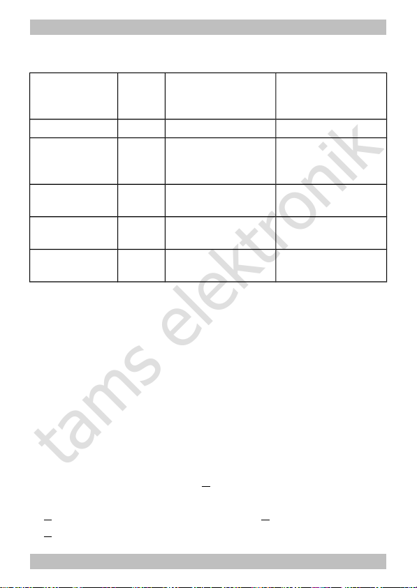
Maximum number of LEDs per PCB connected in series
Forward
voltage of
the LEDs
*1
Nominal /
operating voltage
of the transformer
(=)
*2
Max.
number
of
LEDs
*3
Nominal /
operating voltage
of the transformer
(~)
*2
Max.
number
of
LEDs
*3
2 V 12 V / 12 V 5 12 V / approx. 17 V 7
4 V 12 V / 12 V 2 12 V / approx. 17 V 3
2 V 16 V / 16 V 7 16 V / approx. 22 V 10
4 V 16 V / 16 V 3 16 V / approx. 22 V 5
2 V 18 V / 18 V 8 18 V / approx. 25 V 11
4 V 18 V / 18 V 4 18 V / approx. 25 V 5
*1
The forward voltage of white and blue LEDs is approx. 4 V, differing coloured LEDs approx.
2 V.
*2
Nominal voltage and operating voltage: The operating voltage with a.c. transformers is
approx. 1,4 times the nominal voltage given on the transformer. With d.c. power packs the
operating voltage corresponds to the given nominal voltage.
*3
Tolerance and / or voltage fluctuations in practice often cause the calculated operating
voltage not being available. For that reason it is recommended to connect one LED less than
possible in theory.
Page 14
Page 15

tams elektronik
!
LED-Control English
Connect the LED(s) according
to the connection diagramm to
the connecting points X1 and
X2.
Connecting train rear lanterns:
Caution:
The LEDs shaped like train
rear lanterns have to be
mounted according to the
connection diagram! The
longer lead is not in general
the anode (+)!
Mounting the train rear lanterns
In order to fix a LED shaped like a train rear lantern safely, it is
recommended to use a PCB of its own for each LED.
Fix the PCB on the inside of the carriage´s board beside the holes
needed to feed through the legs of the LED. Take care to mount the
connecting points for the LED directly beside the holes. Bend the legs of
the LED in direction of the PCB, when fed through the hole. Shorten the
legs so that they end directly above the connecting points and then
solder them.
Page 15
Page 16

tams elektronik
English LED-Control
Note: The LED should be mounted with a small distance to the back of
the carriage like in reality. Use a match as a spacer while mounting the
LED.
Info: Electrolytic capacitors
Electrolytic capacitors are often used to store energy. One of the two
leads is marked with a minus sign which indicates the mounting
orientation. The value is given on the casing.
Electrolytic capacitors are available with different voltage sustaining
capabilities and capacities. The maximum capacity only depends on the
space available for mounting the capacitor (the higher the capacity the
bigger the capacitor). Using an electrolytic capacitor with a voltage
sustaining capability higher than required is always possible.
Connecting a bridging capacitor
In order to supply the LEDs in currentless parts you can mount an
additional capacitor to the PCB. It is recommended to choose a
capacitor with a capacity as high as possible. The minimum voltage
sustaining capability of the capacitor depends on the power supply:
Power supply Voltage sustaining capability of the bridging
capacitor
< 18 V > 16 V
> 18 V > 25 V
Please note: When connecting the PCB to a decoder output intended to
be dimmed, you should not mount a bridging capacitor.
Page 16
Page 17

tams elektronik
!
LED-Control English
7. Check list for troubleshooting
Parts are getting very hot and/or start to smoke.
Disconnect the system from the mains immediately!
Possible cause: The connections to the power supply are connected
the wrong round. à Check the connection. In this case the PCB and
the connected LEDs are probably damaged irreparably.
The LED(s) does / do not light.
Possible cause: The connection to the power supply is interrupted.
à Check the connections.
Possible cause: If connected to direct (analogue) voltage the
connections "+" and "-" are incorrectly connected. à Check the
connections.
The LED(s) only lights / light in one direction of motion.
Possible cause: There is no rectifier mounted in series although
connected to direct voltage. à Mount a rectifier.
Hotline: If problems with your module occur, our hotline is pleased to
help you (mail address on the last page).
Repairs: You can send in a defective module for repair (address on the
last page). In case of guarantee the repair is free of charge for you.
With damages not covered by guarantee, the maximum fee for the
repair is 50 % of the sales price according to our valid price list. We
reserve the right to reject the repairing of a moduel when the repair is
impossible for technical or economic reasons.
Please do not send in modules for repair charged to us. In case of
warranty we will reimburse the forwarding expenses up to the flat rate
we charge according to our valid price list for the delivery of the
product. With repairs not covered by guarantee you have to bear the
expenses for sending back and forth.
Page 17
Page 18

tams elektronik
English LED-Control
8. Guarantee bond
For this product we issue voluntarily a guarantee of 2 years from the
date of purchase by the first customer, but in maximum 3 years after
the end of series production. The first customer is the consumer first
purchasing the product from us, a dealer or another natural or juristic
person reselling or mounting the product on the basis of selfemployment. The guarantee exists supplementary to the legal warranty
of merchantability due to the consumer by the seller.
The warranty includes the free correction of faults which can be proved
to be due to material failure or factory flaw. With kits we guarantee
the completeness and quality of the components as well as the function
of the parts according to the parameters in not mounted state. We
guarantee the adherence to the technical specifications when the kit
has been assembled and the ready-built circuit connected according to
the manual and when start and mode of operation follow the
instructions.
We retain the right to repair, make improvements, to deliver spares or
to return the purchase price. Other claims are excluded. Claims for
secondary damages or product liability consist only according to legal
requirements.
Condition for this guarantee to be valid, is the adherence to the
manual. In addition, the guarantee claim is excluded in the following
cases:
if arbitrary changes in the circuit are made,
if repair attempts have failed with a ready-built module or device,
if damaged by other persons,
if damaged by faulty operation or by careless use or abuse.
Page 18
Page 19

tams elektronik
LED-Control English
9. Declaration of conformity
This product conforms with the EC-directives mentioned below
and is therefore CE certified.
2004/108/EG on electromagnetic. Underlying standards: EN 55014-1
and EN 61000-6-3. To guarantee the electromagnetic tolerance in
operation you must take the following precautions:
Connect the transformer only to an approved mains socket installed
by an authorised electrician.
Make no changes to the original parts and accurately follow the
instructions, connection diagrams and PCB layout included with this
manual.
Use only original spare parts for repairs.
2011/65/EG on the restriction of the use of certain hazardous
substances in electrical and electronic equipment (ROHS). Underlying
standard: EN 50581.
10. Declarations conforming to the WEEE directive
This product conforms with the EC-directive 2012/19/EG on
waste electrical and electronic equipment (WEEE).
Don´t dispose of this product in the house refuse, bring it to the next
recycling bay.
Page 19
Page 20

tams elektronik
n
n
n
Information and tips:
n
http://www.tams-online.de
n
n
n
n
Warranty and service:
n
Tams Elektronik GmbH
n
Fuhrberger Straße 4
DE-30625 Hannover
n
fon: +49 (0)511 / 55 60 60
fax: +49 (0)511 / 55 61 61
n
e-mail: modellbahn@tams-online.de
n
n
 Loading...