

Page 1
tams elektronik
Manual
Locomotive decoders
LD-G-32.2 and LD-W-32.2
LD-G-32.2
Item no. 41-01420
Item no. 41-01421
Item no. 41-01422
LD-W-32.2
Item no. 41-02420
Item no. 41-02421
tams elektronik
n n n
DCC MM
Page 2

tams elektronik
English LD-G-32.2 and LD-W-32.2
Contents
1. Getting started............................................................................4
2. Safety instructions.......................................................................6
3. Safe and correct soldering...........................................................9
4. Operation overview...................................................................10
4.1. Modes of operation............................................................10
4.2. Driving of the motor..........................................................12
4.3. Function outputs...............................................................14
4.4. Releasing the functions......................................................15
4.5. Automated processes.........................................................15
4.6. Feedback with RailCom**..................................................16
5. Technical specifications..............................................................17
6. Connections..............................................................................18
6.1. Connector pin assignment LD-G-32.2..................................19
6.2. Connector pin assignment LD-W-32.2.................................20
6.3. Using decoders with interface connectors...........................21
6.4. Use in locomotives with a.c. motor.....................................21
6.5. Mounting decoders without interface..................................22
6.6. Connecting LEDs to the function outputs............................24
6.7. Connecting inductive loads.................................................26
6.8. Connecting accessories via a relay......................................26
6.9. Connecting a buffer capacitor.............................................27
6.10.Fixing the decoder.............................................................27
7. Programming............................................................................28
8. Configuration variables and registers..........................................30
9. Check list for troubleshooting.....................................................41
Page 2
Page 3

tams elektronik
LD-G-32.2 and LD-W-32.2 English
10. Guarantee bond........................................................................43
11. EU declaration of conformity......................................................44
12. Declarations conforming to the WEEE directive...........................44
© 07/2018 Tams Elektronik GmbH
All rights reserved. No part of this publication may be reproduced or
transmitted in any form or by any means, electronic or mechanical,
including photocopying, without prior permission in writing from Tams
Elektronik GmbH.
Subject to technical modification.
The asterisks **
RailCom® is the registered trademark of:
Lenz Elektronik GmbH | Vogelsang 14 | DE-35398 Gießen
To increase the text´s readability we have refrained from refering to
this point in each instance.
This manual mentions the following companies:
Gebr. MÄRKLIN & Cie. GmbH | Stuttgarter Str. 55-57 |DE-73033 Göppingen
Uhlenbrock Elektronik GmbH | Mercatorstraße 6 | DE-46244 Bottrop
Page 3
Page 4

tams elektronik
English LD-G-32.2 and LD-W-32.2
1. Getting started
How to use this manual
This manual gives step-by-step instructions for safe and correct fitting and
connecting of the decoder, and operation. Before you start, we advise you
to read the whole manual, particularly the chapter on safety instructions
and the checklist for trouble shooting. You will then know where to take
care and how to prevent mistakes which take a lot of effort to correct.
Keep this manual safely so that you can solve problems in the future. If
you pass the decoder on to another person, please pass on the manual
with it.
Intended use
The locomotive decoders LD-G-32.2 and LD-W-32.2 are designed to be
operated according to the instructions in this manual in model building,
especially in digital model railroad layouts. Any other use is
inappropriate and invalidates any guarantees.
The locomotive decoders should not be mounted by children under the
age of 14.
Reading, understanding and following the instructions in this manual
are mandatory for the user.
Page 4
Page 5
tams elektronik
LD-G-32.2 and LD-W-32.2 English
Checking the package contents
Please make sure that your package contains:
one or five locomotive decoders, depending on the version with or
without soldered connecting wires resp. with or without interface
connector;
a CD (containing the manual and further information).
N.B. For technical reasons it is possible that the PCB is not completely
inserted. This is not a fault.
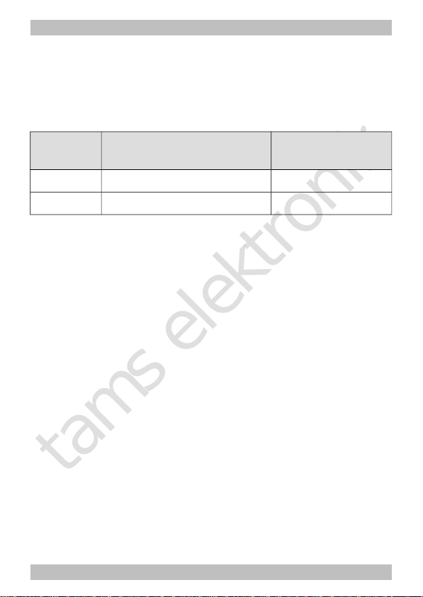
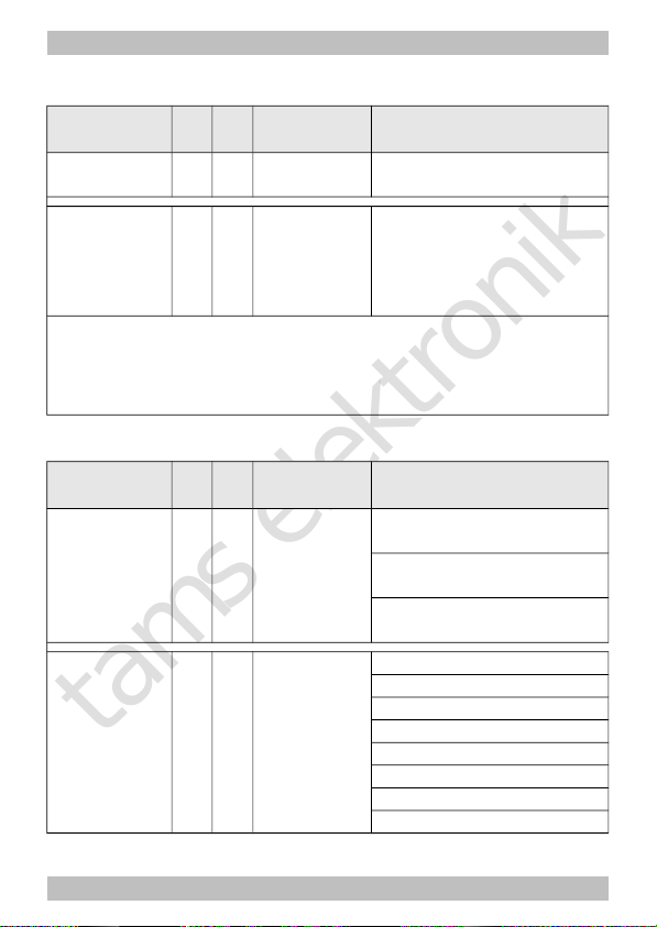
Available versions
Connecting wires /
Interface
LD-G-32.2 LD-W-32.2
without wires + +
with wires + +
according to NEM 650 8- pole (NEM 652) –
according to NEM 658 – –
according to NEM 660 – –
Required materials
For mounting and connecting decoders without interface you need:
an electronic soldering iron (max. 30 Watt) or a regulated soldering
iron with a fine tip and a soldering iron stand,
a tip-cleaning sponge,
a heat-resistant mat,
a small side cutter, a wire stripper and a pair of tweezers,
electronic tin solder (0.5 mm diameter).
Page 5
Page 6
tams elektronik
!
English LD-G-32.2 and LD-W-32.2
In order to connect decoders without interface or soldered connecting
wires you will need wire. Recommended cross sections:
> 0,04 mm² for the connections to the function outputs;
> 0,05 mm² for the connections to the motor and current collectors.
If you want to connect a decoder LD-G-32.2 to an a.c. motor you need:
a load control adapter LRA (item no. 70-02105 or 70-02106) or
a permanent magnet (e.g. item no. 70-04100, 70-04200 or 70-
04300) or
a motor modification set (e.g. item no. 70-40110, 70-40210 or 70-
40310).
In order to bridge short current interruptions you need:
an electrolytic capacitor with a capacity of 100 to 470 µF and a
proof voltage of minimum 35 V.
2. Safety instructions
Caution:
Integrated circuits (ICs) are inserted on the decoder. They are
sensitive to static electricity. Do not touch components without first
discharging yourself. Touching a radiator or other grounded metal part
will discharge you.
Mechanical hazards
Cut wires can have sharp ends and can cause serious injuries. Watch
out for sharp edges when you pick up the PCB.
Visibly damaged parts can cause unpredictable danger. Do not use
damaged parts: recycle and replace them with new ones.
Page 6
Page 7

tams elektronik
LD-G-32.2 and LD-W-32.2 English
Electrical hazards
Touching powered, live components,
touching conducting components which are live due to malfunction,
short circuits and connecting the circuit to another voltage than
specified,
impermissibly high humidity and condensation build up
can cause serious injury due to electrical shock. Take the following
precautions to prevent this danger:
Never perform wiring on a powered module.
Assembling and mounting the kit should only be done in closed,
clean, dry rooms. Beware of humidity.
Only use low power for this module as described in this manual and
only use certified transformers.
Connect transformers and soldering irons only in approved mains
sockets installed by an authorised electrician.
Observe cable diameter requirements.
After condensation build up, allow a minimum of 2 hours for dispersion.
Use only original spare parts if you have to repair the kit or the
ready-built module.
Fire risk
Touching flammable material with a hot soldering iron can cause fire, which
can result in injury or death through burns or suffocation. Connect your
soldering iron or soldering station only when actually needed. Always keep
the soldering iron away from inflammable materials. Use a suitable
soldering iron stand. Never leave a hot soldering iron or station unattended.
Page 7
Page 8
tams elektronik
!
English LD-G-32.2 and LD-W-32.2
Thermal danger
A hot soldering iron or liquid solder accidentally touching your skin can
cause skin burns. As a precaution:
use a heat-resistant mat during soldering,
always put the hot soldering iron in the soldering iron stand,
point the soldering iron tip carefully when soldering, and
remove liquid solder with a thick wet rag or wet sponge from the
soldering tip.
Dangerous environments
A working area that is too small or cramped is unsuitable and can cause
accidents, fires and injury. Prevent this by working in a clean, dry room
with enough freedom of movement.
Other dangers
Children can cause any of the accidents mentioned above because they
are inattentive and not responsible enough. Children under the age of
14 should not be allowed to work with this kit or the ready-built
module.
Caution:
Little children can swallow small components with sharp edges, with
fatal results! Do not allow components to reach small children.
In schools, training centres, clubs and workshops, assembly must be
supervised by qualified personnel.
In industrial institutions, health and safety regulations applying to
electronic work must be adhered to.
Page 8
Page 9

tams elektronik
!
LD-G-32.2 and LD-W-32.2 English
3. Safe and correct soldering
Caution:
Incorrect soldering can cause dangers through fires and heat. Avoid
these dangers by reading and following the directions given in the
chapter Safety instructions.
Use a small soldering iron with max. 30 Watt. Keep the soldering tip
clean so the heat of the soldering iron is applied to the solder point
effectively.
Only use electronic tin solder with flux.
When soldering electronic circuits never use soldering-water or
soldering grease. They contain acids that can corrode components
and copper tracks.
Solder quickly: holding the iron on the joints longer than necessary can
destroy components and can damage copper tracks or soldering eyes.
Apply the soldering tip to the soldering spot in such a way that the
wire and the soldering eye are heated at the same time.
Simultaneously add solder (not too much). As soon as the solder
becomes liquid take it away. Hold the soldering tip at the spot for a
few seconds so that the solder flows into the joint, then remove the
soldering iron.
The joint should be held still for about 5 seconds after soldering.
To make a good soldering joint you should use a clean and
unoxidised soldering tip. Clean the soldering tip with a damp piece of
cloth, a damp sponge or a piece of silicon cloth.
After soldering check (preferably with a magnifying glass) tracks for
accidental solder bridges and short circuits. This would cause faulty
operation or, in the worst case, permanent damage. You can remove
excess solder by putting a clean soldering tip on the spot. The solder
will become liquid again and flow from the soldering spot to the
soldering tip.
Page 9
Page 10

tams elektronik
English LD-G-32.2 and LD-W-32.2
4. Operation overview
4.1. Modes of operation
Digital operation
The locomotive decoder is a multiple protocol decoder, that can operate
with and automatically recognise both DCC or Motorola formats.
The number of addresses is dependant on the format being used:
Motorola-Format: 255 addresses,
DCC-Format: 127 Basis-addresses or 10.239 extended addresses.
In the DCC format the decoder can be driven in all speed levels (14, 28
or 128). In the Motorola format the decoder can be driven in 14 or 27
speed levels. Driving all 27 speed levels can be done only with central
units which support this mode (e.g. MasterControl). With central units
which allow 14 speed levels only, it is only possible to select every
second speed level.
Programming the decoders is done:
in Motorola format by setting the registers,
in DCC format by setting the configuration variables (direct
programming, DCC conform) or by POM (programming on main =
main track programming).
Page 10
Page 11

tams elektronik
!
LD-G-32.2 and LD-W-32.2 English
Analogue mode
The locomotive decoder can also be used in analogue model railway
layouts run with a D.C. speed control, and with restrictions with an A.C.
speed control. When putting the vehicle on the rails the decoder
recognizes automatically if it is run in analogue or digital mode and sets
the corresponding operation mode. The automatic recognition of the
analogue mode can be switched off.
Caution:
Old analogue driving transformers (e.g. models in a blue housing
from Märklin**) are not suitable for use with digital decoders in
analogue operation! These transformers have been designed for the
older supply voltage of 220 V and, due to construction, generate very
high excess voltage impulses when changing the driving direction.
When using them with the modern supply voltage of 230 V too high
excess voltage impulses can occur, damaging electronic parts on the
decoder. For that reason only use driving transformers designed for a
net voltage of 230 V.
Switching the function outputs on or off is not possible in analogue
mode. They can be programmed so that they are either switched on or
off in analogue mode. The effects set for the outputs are active in
analogue mode as well.
Outputs to be switched with F0 are switched on or off in analogue mode
according to the direction of travel. When operated in analogue d.c.
layouts this applies only to lamps or accessories where the return
conductor is connected to the decoder´s common return conductor for all
function outputs.
The decoders´ load control is not active in analogue mode.
Page 11
Page 12
tams elektronik
English LD-G-32.2 and LD-W-32.2
4.2. Driving of the motor
Pulse width modulation
The different decoder types are designed to optimally control their
particular fitting motor types.
Decoder
type
PWM Suitable for coreless
(Faulhaber) motors
LD-G-32.2
32 kHz (fixed) yes
LD-W-32.2 480 or 60 Hz (to be set) no
Load control
The LD-G-32.2 for DC motors has a load control, the LD-W-32.2 for AC
motors do not have this function.
The load control influences the motor voltage to keep the locomotive
with a set speed level at constant velocity, independent of additional
loads (e.g. running up a gradient, coupled carriages).
It is possible to switch on and off the load control by varying a CVvariable of the decoder. The parameters of the load control may be
altered, in order to adapt the decoder to the motor´s individual
characteristics.
Parameters of the load control: The load control is determined by
three parameters which have to be coordinated in order to achieve
optimal driving characteristics. Each of the load control parameters is
assigned to a configuration variable. The parameters are:
KP: The proportional component of the load control ensures the
difference between the set and the present value being as small as
possible. It cannot have the value "0" at any time. This component
affects the basic speed. In case the set value is too small the
locomotive runs too slowly. In case the set value is too high the
locomotive stutters while moving.
Page 12
Page 13

tams elektronik
LD-G-32.2 and LD-W-32.2 English
KI: The integral component of the load control ensures the remaining
difference between the set and the present value is reduced to 0 and so
for the correction of very small divergences. If the set value is too high
the locomotive stutters massively while moving.
KD: The differential component of the load control ensures that the
control is not converted too quickly. Is the set value to low then the
locomotive stutters. If the set value is too high, the locomotive rocks
while moving.
Velocity characteristic
The decoder can be adjusted to the driving characteristics of the motor
and the characteristic speed of the locomotive type, by setting the
starting and maximum velocity. From these two settings the decoder
generates a linear velocity characteristic.
When the speed level mode is set to 28 speed levels, it is possible to
assign any motor voltage to all of the 28 speed levels as an alternative
to the linear velocity characteristic. This allows the programming of a
velocity characteristic which adjusts the individual driving characteristics
of the motor. The set values are saved in the alternative velocity table.
Shunting gear
It is possible to switch into the shunting gear mode via a function key
(in state of delivery F3), when so programmed. In the shunting gear
mode, the velocity of all speed levels is reduced to approx. 50 %
compared to the set velocity.
Acceleration and brake delay
It is possible to program the acceleration and brake delay individually
via the central unit. When so programmed, it can be switched on and
off with a function key (in state of delivery F4).
Page 13
Page 14

tams elektronik
English LD-G-32.2 and LD-W-32.2
Emergency stop
It is possible to carry out an emergeny stop at a change of direction
automatically, when so programmed.
4.3. Function outputs
The decoder has function outputs, which are available to connect
optional accessories (e.g. lighting, smoke generator, sound module,
electric coupling). The accessories´ number and type to be connected
depends on the outputs´number and maximum current as well as on
the maximum total current of the special decoder (see section 5
"Technical specifications").
Effects of the function outputs
It is possible to set the following effects for the function outputs
individually:
Switching on and off depending on the direction of travel.
Flashing and double flashing. Both the frequency and the keying
ratio can be set. E.g. single and double flash lights or strobe lights.
Dimming: Example of use: The electric bulbs of older vehicles made
for analogue operation can be dimmed and thus must not be
exchanged after the mounting of the decoder.
Shunting light: You can program the outputs so that they are switched on
generally during shunting operation (to be switched with F3 or F4). The
dependence on the direction of travel will be nullified for these outputs
during shunting operation.
Page 14
Page 15
tams elektronik
LD-G-32.2 and LD-W-32.2 English
4.4. Releasing the functions
The function outputs can be released by pushing the function keys. The
mapping of the outputs to the function keys and the switching inputs is
arbritary. It is possible to assign several function keys and switching
inputs to one output.
Outputs DCC format MM format
AUX1 to AUX3 F0 to F12 F0 to F4 or
F5 to F9
(= F0 to F4 of a second
decoder address)
4.5. Automated processes
The control software in the locomotive decoder allows you to automate
procedures and to reduce complex processes to one keystroke.
Dimming depending on the velocity
You can automatically switch functions depending on the velocity when
reaching a speed level defined in a CV. You assign an individual voltage
to the function outputs for the ranges of speed levels underneath and
above the defined speed level. This allows for example to switch on and
off the high beam light, to control the cab light or to influence the
intensity of the steam output.
Shunting function
You can assign the shunting gear and the shunting light to the same funtion
key. That way you switch on the shunting light automatically when
switching into the shunting gear (and thus reducing the velocity).
Page 15
Page 16

tams elektronik
English LD-G-32.2 and LD-W-32.2
4.6. Feedback with RailCom**
RailCom is a log for bi-directional communication in digital model
railway layouts controlled in DCC-format. It allows e.g. the feedback of
the address and the CV values from the decoder to the digital central
unit or to special receivers (so-called detectors). The decoders must be
designed to send the RailCom messages.
When so programmed, the locomotive decoders LD-G-32.2 and LD-W-
32.2 send (continuously) the (basic, extended or consist) address to the
detectors (so-called RailCom broadcast datagramm) and transfer a CV
message after a DCC CV read-out command.
Sending RailCom messages is only possible in layouts with a DCC signal
on the rails. It is not possible to use the RailCom-function in a pure
Motorola environment.
Page 16
Page 17
tams elektronik
LD-G-32.2 and LD-W-32.2 English
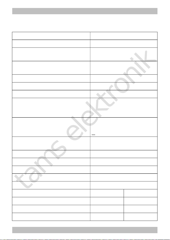
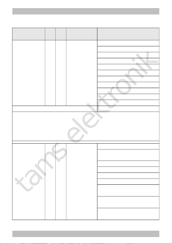
5. Technical specifications
Data format DCC and MM
Feedback log RailCom
Supply voltage 12-24 V digital voltage or
max. 18 V analogue voltage
Current consumption
(without connected loads) max. 40 mA
Max. total current 1.500 mA
Max. current for motor 1.000 mA
Number of outputs 3
Max. current / output
AUX1: 300 mA
AUX2: 300 mA
AUX3: 200 mA
Connection for buffer capacitor
Capacity
Proof voltage
1
100 to 470 µF
> 35 V
Interface
(depending on the decoder type and the version)
according to NEM 652
Protected to IP 00
Ambient temperature in use 0 ... +60 °C
Ambient temperature in storage -10 ... +80 °C
Comparative humidity allowed max. 85 %
Dimensions PCB
approx. 22x17x6 mm
Weight LD-G-32.2 LD-W-32.2
without wires
approx. 1.4 g approx. 1.3 g
with wires
approx. 2.3 g approx. 1.9 g
NEM 652 approx. 2.5 g ---
Page 17
Page 18

tams elektronik
!
English LD-G-32.2 and LD-W-32.2
6. Connections
Note the following comment in order to protect the
decoder from (maybe irreparable) damage!
Avoid all conducting connections between the decoder and
accessories connected to the decoder´s common return conductor for
all function outputs on the one hand and metal parts of the vehicle or
the rails on the other hand. Connections result for example from badly
isolated connecting wires (as well at the stripped ends of connecting
wires not in use) or insufficient fixing and isolating the decoder or the
accessory, for example. Risk of short circuit! In this case the overload
protection of the decoder is not able to protect the decoder from
damage.
Before connecting the motor, lighting or other accessories check if
their current is below the maximum permissible values and the total
current is below the safe load. Should the permissible current be
exceeded, this can result in damage to the decoder.
You should under no circumstances connect the decoder´s common
return conductor for all function outputs to vehicle ground. Risk of
short circuit!
Old analogue driving transformers (e.g. models in a blue housing from
Märklin**) are not suitable for use with digital decoders in analogue
operation! These transformers have been designed for the older
supply voltage of 220 V and, due to construction, generate very high
excess voltage impulses when changing the driving direction. When
using them with the modern supply voltage of 230 V too high excess
voltage impulses can occur, damaging electronic parts on the
decoder. For that reason only use driving transformers designed for a
net voltage of 230 V.
Page 18
Page 19
tams elektronik
LD-G-32.2 and LD-W-32.2 English
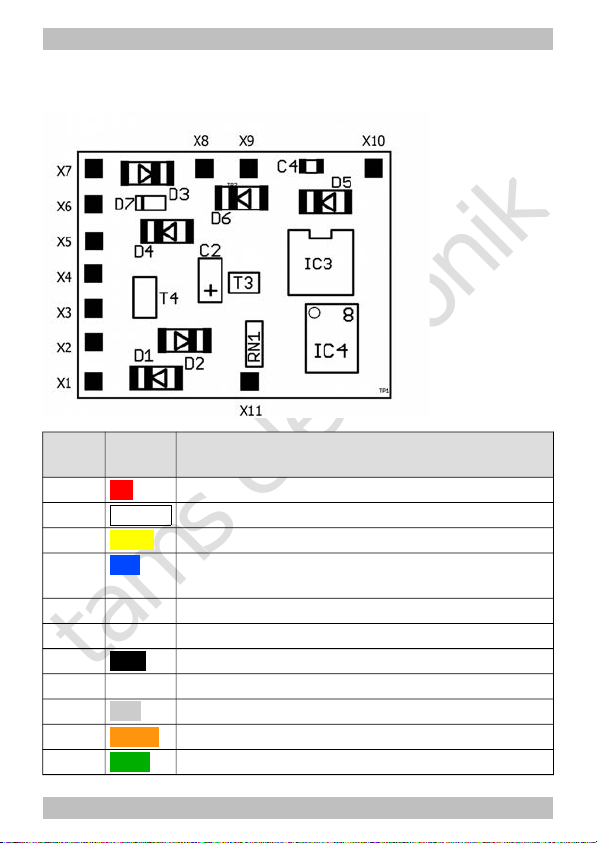
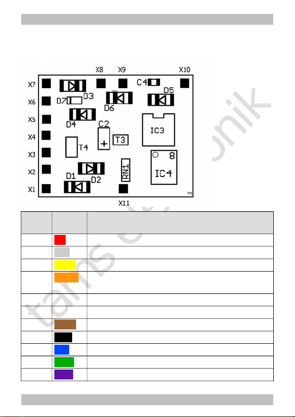
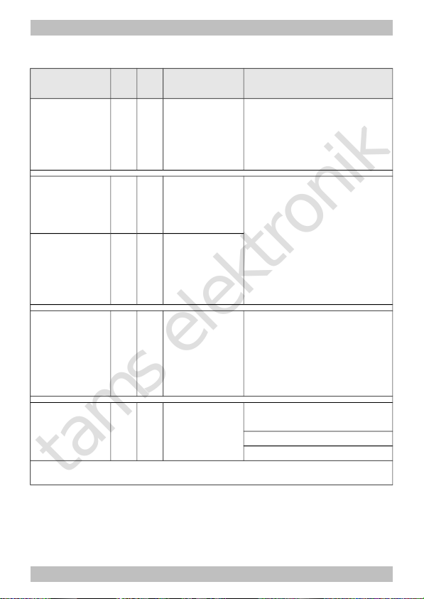
6.1. Connector pin assignment LD-G-32.2
Versions: 8-pole plug (NEM652), with or without wires
LD-G-32.2
Colour
of wire
Connection to
(for use of settings in state of delivery)
X1 red Right current collector (or slider)
X2
white
AUX1 = lighting forward motion (function key F0)
X3 yellow AUX2 = lighting backward motion (function key F0)
X4 blue RL = common return conductor for all function
outputs (+)
X5 Positive pole (+) of buffer capacitor
X6 Negative pole (-) of buffer capacitor
X7 black Left current collector (or vehicle ground)
X8 --- not occupied
X9 grey Motor connection 2 (minus)
X10 orange Motor connection 1 (plus)
X11 green AUX3 (function key F1) | max. current: 200 mA
Page 19
Page 20
tams elektronik
English LD-G-32.2 and LD-W-32.2
6.2. Connector pin assignment LD-W-32.2
Versions: without / with wires
LD-W-32.2
Colour
of wire
Connection to
(for use of settings in state of delivery)
X1 red Right current collector (or slider)
X2 grey AUX1 = lighting forward motion (function key F0)
X3 yellow AUX1 = lighting backward motion (function key F0)
X4 orange RL = common return conductor for all function
outputs (+)
X5 Positive pole (+) of buffer capacitor
X6 Negative pole (-) of buffer capacitor
X7 brown Left current collector (or vehicle ground)
X8 black Motor connection 3
X9 blue Motor connection 2
X10 green Motor connection 1
X11 violet AUX3 (function key F1) | max. current: 200 mA
Page 20
Page 21
tams elektronik
LD-G-32.2 and LD-W-32.2 English
6.3. Using decoders with interface connectors
Many recent locomotives with d.c. motor are equipped ex works with an
interface socket. Using a decoder with a suitable connector saves
separating the connections and soldering works at the locomotive.
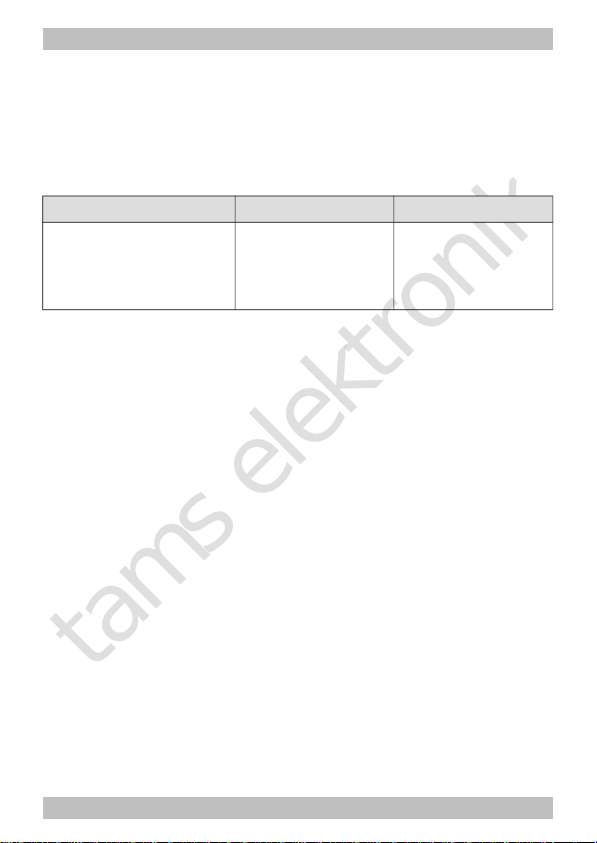
Possible versions:
Description Number of poles MOROP standard
6 pole 6 NEM 651
8 pole 8 NEM 652
The interface enables you to connect the decoder to the motor, the rail
current collectors, the lighting and – provided the special connector is
designed for it – additional accessories.
When mounting decoders with 6-pole interface connectors according to
NEM 651 or 8-pole interface connectors according to NEM 652, take
care to put the markings on the connector and on the socket on top of
each other.
6.4. Use in locomotives with a.c. motor
The LD-G-32.2 has been designed to control direct current (d.c.)
motors, for that reason it cannot be connected directly to alternating
current (a.c.) motors. You can control a.c. motors with the LD-G-32.2
and benefit of the load control when
mounting a load control adapter between a.c. motor and decoder or
replacing the field coil of the a.c. motor by a permanent magnet.
Page 21
Page 22
tams elektronik
!
English LD-G-32.2 and LD-W-32.2
6.5. Mounting decoders without interface
Locate the position for the decoder after opening the locomotive
housing. Disconnect the motor from the rail current collectors or the
change-over switch from the motor and rails if you have a locomotive
with electronic change-over switch. The change-over switch is no
longer necessary, you can remove it.
Caution:
The interference suppression devices mounted to the motor or the
connecting wire must not be removed! Motor and interference
suppression devices are one unit. If even one part is removed, it can
cause extreme interference!
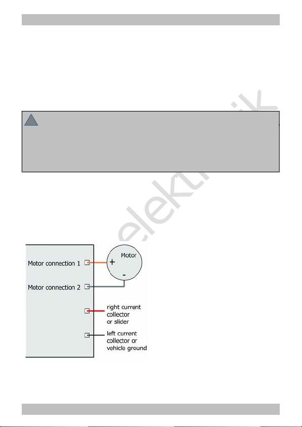
Connecting the decoder to the motor
Connect the decoder to the rail current collectors and to the motor.
Should the locomotive´s direction of motion in analogue mode not
match the direction of motion set at the speed control you have to
swap the connections to the rail current collectors / the slider.
Fig. 1: Connection of
an d.c. motor and the
power supply
Page 22
Page 23
tams elektronik
LD-G-32.2 and LD-W-32.2 English
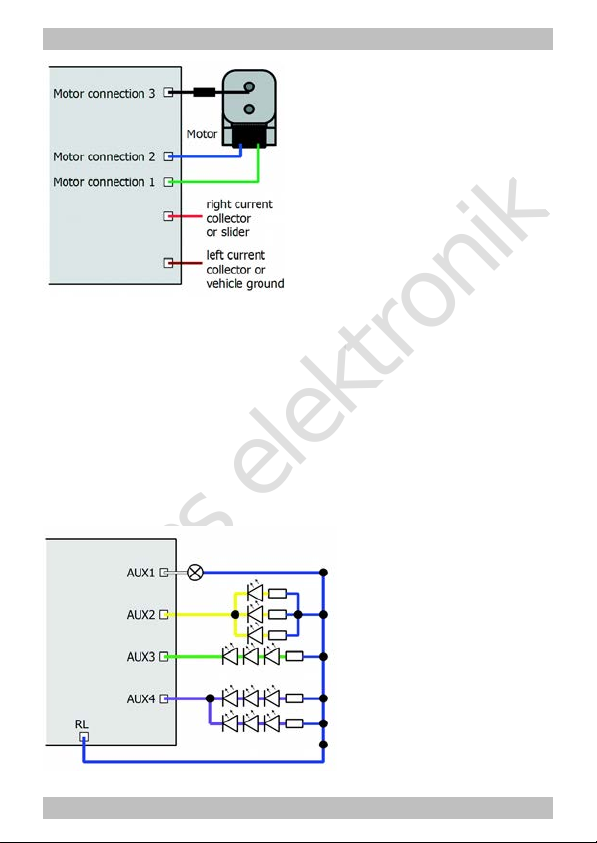
Fig. 2: Connection of
an a.c. motor and the
power supply
Connecting accessories to the outputs
Disconnect any existing diodes in the leads to the lamps, otherwise the
lamps might not light. Connect the lamps and the accessories to the
function outputs of the decoder. If the lamp or the accessory is already
connected with one side to vehicle ground, the connection is complete.
If not, connect the second side of the lamp or the accessory to the
decoder´s common return conductor for all function outputs.
You find the factory (default) settings in the lists with the connector pin
assignments. You can assign the outputs to the function keys
voluntarily by setting the configuration variables.
Fig. 3: Examples for the
connection of accessories
and LEDs to the function
outputs
AUX2: parallel connection
of LEDs
AUX3: serial connection of
LEDs
AUX4: combined parallel
and serial connection of
LEDs
Page 23
Page 24

tams elektronik
!
English LD-G-32.2 and LD-W-32.2
6.6. Connecting LEDs to the function outputs
The decoder´s function outputs switch respective to the decoder
ground. For that reason you must connect the cathodes (-) of the LEDs
to the function outputs and the anodes (+) to the decoder´s common
return conductor for all function outputs.
Caution:
If you use light-emitting diodes (LEDs) you must always operate them via
a series resistor, otherwise they will be damaged when put into operation
or their duration of life will be reduced considerably!
When doing without a series resistor, other components undertake the
series resistor´s function (e.g. rails, wheels, current connectors), possibly
leading to a modification of the data signal and thus to disturbances in
digital operation.
Always determine the necessary series resistor´s value for the peak
value of the available operating voltage. With regulated boosters this
corresponds to the specified boosters´ output (= track) voltage. With
not regulated boosters or analogue driving transformers the peak
value is approx. 1,4 fold the nominal voltage specified on the
transformer.
Serial connection of LEDs
When you want to connect several LEDs to one output you can switch them
in series via a common series resistor. The current consumption is max. 20
mA for all LEDs, depending on the series resistor´s value. The maximum
number of LEDs to be connected in series results from
Peak value of the operating voltage
- sum of the forward voltages of all LEDs
> 0
The advantage of this solution is the low current consumption.
In order to determine the necessary series resistor for a serial LED´s
Page 24
Page 25

tams elektronik
LD-G-32.2 and LD-W-32.2 English
connection first add the forward voltages of all LEDs. The forward
voltages depend on the lighting colour and should be given in the
technical specifications. In case there is no manufacturer information
available, you can take as a basis 4 V for white and blue LEDs and 2 V
for yellow, orange, red and green LEDs.
The remaining voltage has to be "eliminated" by a resistor. The formula
for the calculation of the resistor is:
required RV [Ohm] = ( UB [V] – ∑ UF [V] ) / (IF [mA] x 0.001)
UB = operating voltage (peak value) | ∑ UF = sum of the forward voltages of all LEDs
IF = current with max. luminosity
Parallel connection of LEDs
Alternatively, you can connect several LEDs in parallel, each via a series
resistor of its own. The current consumption is max. 20 mA for all LEDs,
depending on the series resistor´s value. The maximum number of LEDs to
be connected in parallel results from
maximum current at the output
- sum of the current consumption of all LEDs
> 0
Advantageous with this solution is that the LEDs already lighten when
their forward voltage has been reached (2 to 4 V, depending on the
fluorescent colour), which makes this solution suitable for analogue
mode. Disadvantageous is the high current consumption.
The formula for the calculation of the resistor is:
required RV [Ohm] = ( UB [V] – UF [V] / (IF [mA] x 0.001)
UB = operating voltage (peak value) | UF = forward voltage of the LED
IF = current with max. luminosity
In order to save current, you can limit the LEDs´current consumption to
10 mA, which normally does not cause a visible loss of luminance.
Page 25
Page 26

tams elektronik
English LD-G-32.2 and LD-W-32.2
6.7. Connecting inductive loads
When connecting inductive loads (e.g. TELEX couplings, relays or other
accessories with coils), you should switch a free-wheeling diode (e.g.
1N400x) in parallel, in order to avoid damage at the output. Check to
connect the anode of the diode to the function output.
6.8. Connecting accessories via a relay
When you want to switch an accessory / accessories via the decoder,
which connection would lead to exceeding the maximum current at the
output or of the decoder, you can switch the accessories via a relay
(e.g. 1xUm 1A 12V, item-no. 84-61010) and connect them directly to
the vehicle´s current collector.
The current consumed by the relay depends on its type. The relay named in
the example needs approx. 100 mA.
As described in the section "Connecting inductive loads" you should
switch a free-wheeling diode (e.g. 1N400x) in parallel to the relay.
Fig. 4: Connection of an accessory via a relay
Page 26
Page 27

tams elektronik
LD-G-32.2 and LD-W-32.2 English
6.9. Connecting a buffer capacitor
In sections with bad contact to the rails the power supply of the
decoder can be interrupted. Possible consequences are e.g. flickering
lighting. In these and similar cases you can find a remedy by
connecting a buffer capacitor.
The electrolytic capacitor should have a capacity of minimum 100 µF
and a proof voltage of minimum 35 V. Observe the correct polarity
when connecting the capacitor!
6.10. Fixing the decoder
After having finished all connections you should fix the decoder, to
avoid short circuits by contact to metal parts of the vehicle, for
example. You can use double sided adhesive tape for it or a decoder
holder (item no. 70-01810 or 70-01820), for example.
Page 27
Page 28

tams elektronik
English LD-G-32.2 and LD-W-32.2
7. Programming
Programming with DCC central units
You can program the configuration variables (CV) of the decoder from
the digital central unit, you can use main track programming as well.
See the chapter in the manual of your central unit where the byte wise
programming of configuration variables (CVs) (Direct programming)
and main track programming (POM) are explained. With central units
that allow only register-programming it is only possible to program the
variables CV 1, CV 2, CV 3, CV 4 and CV 29 (= register 1 to 5).
Programming with Motorola central units
In Motorola format the settings are saved in registers.
Please note: If you use a central unit for both DCC and Motorola format
it is recommended to program the decoder in the DCC format. After
having finished programming the decoder it is possible to control it in
Motorola format as well.
Please note: You should connect a lamp or a LED to at least AUX1 or
AUX2 before starting to program the decoder with a Motorola central
unit, as the decoder shows the status of the programming by flashing
the lighting connected to these outputs. The flashing frequency shows,
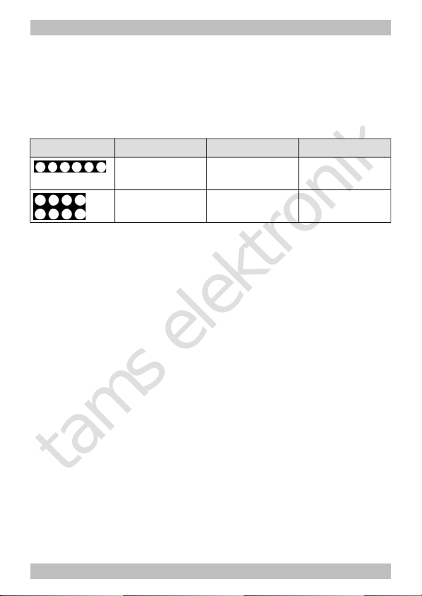
which input the decoder expects:
Slow flashing Fast flashing
Number of the register to be
programmed
Value of the register to be
programmed
Put the vehicle on a track oval or a track section connected to the
central unit’s track output (not to the connection for the programming
track). Make sure no other vehicle than the one you intend to program
is set on the track as the decoder inside this vehicle might be
programmed as well.
Page 28
Page 29

tams elektronik
LD-G-32.2 and LD-W-32.2 English
Starting
the programming mode
Programming the decoder
1. Switch on the central unit or
perform a reset at the central
unit (pushing "stop" and "go")
simultaneously.
2. Set the current decoder
address (default value: 3) or
the address "80".
3. Set all functions to "off".
4. Push button "stop"
à switch off the track voltage.
5. Operate the direction switch
and hold it in that position.
Push the button "go" at once.
6. As soon as the lighting
flashes, release the
direction switch.
1. Enter the number of the
register as a Motorola-address.
If necessary: with a leading "0".
2. Operate the direction switch.
à Lighting flashes faster.
3. Enter the value you want to
set into the register
(as Motorola-address).
4. Operate the direction switch.
à Lighting flashes more slowly.
Repeat steps 1 – 4
for all registers.
Push button "stop".
à Programming mode à End of programming mode.
Programming with Motorola central units with restricted input
options
Some central units do not allow but input values up to 80 or 99. With
the auxillary register 62 values above 80 can be entered.
Programming with the Central Station and the Mobile Station
With the Central Station I or the Mobile Station of Märklin** you can
program the registers. Select the article no. 29750 from the locomotive
database and program the decoder as described for this article in the
Central Station´s or Mobile Station´s manual.
Page 29
Page 30

tams elektronik
English LD-G-32.2 and LD-W-32.2
Programming with the CV-Navi
Instead of programming the configuration variables or registers of the
decoder using the digital central unit, you can use the free software CVNavi. You will find the free download under:
www.tams-online.de
A central unit RedBox or Master Control is required for using the software.
8. Configuration variables and registers
The following lists shows all configuration variables (for the DCC
format) and registers (for the Motorola format), that can be set for the
locomotive decoders.
In the lists you will find in the column "CV-no." the numbers of the
configuration variables for programming in DCC format and in the
column "Rg.-no." the numbers of the registers for programming in
Motorola format. The defaults are those values set in the state of
delivery and after a reset.
Please note: With variables destined to set several parameters, the
input value has to be calculated by adding the numerical values
assigned to the desired parameters.
Page 30
Page 31

tams elektronik
LD-G-32.2 and LD-W-32.2 English
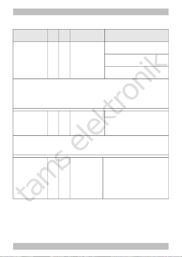
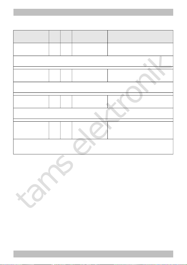
Setting the address
Name of CVs /
registers
CVno.
Rgno.
Input value
(Default)
Remarks and Tips
Basic address 1 01 1 ... 255
(3)
Range of values in
DCC-Format: 1 ... 127
Tip: If a value higher than 127 is set for the basic address and the use of extended addresses
in CV 29 is set to off, the decoder does not react to signals in DCC format!
Extended
address
17 04 192 ... 255
(192)
Only for DCC format. Most
central units permit entering
extended addresses directly.
The CVs 17, 18 and 29 are
set automatically to the
proper values.
18 05 0 ... 255
(255)
Consist
address
19 53 1 ... 127 (0)
= 2nd adress
In DCC format only!
2nd Motorola
address
114 40 1… 255 (4)
= Address needed to switch
additional functions in
Motorola format. The
function keys F5 to F8 are
reached via the function
keys F1 to F4, the function
key F9 via the function key
F0.
Information / Read only
Name of CVs /
registers
CVno.
Rgno.
Input value
(Default)
Remarks and Tips
Version 7 –- ---
Read only in DCC format!
Manufacturer 8 –- --- (62)
Read only in DCC format!
Page 31
Page 32
tams elektronik
English LD-G-32.2 and LD-W-32.2
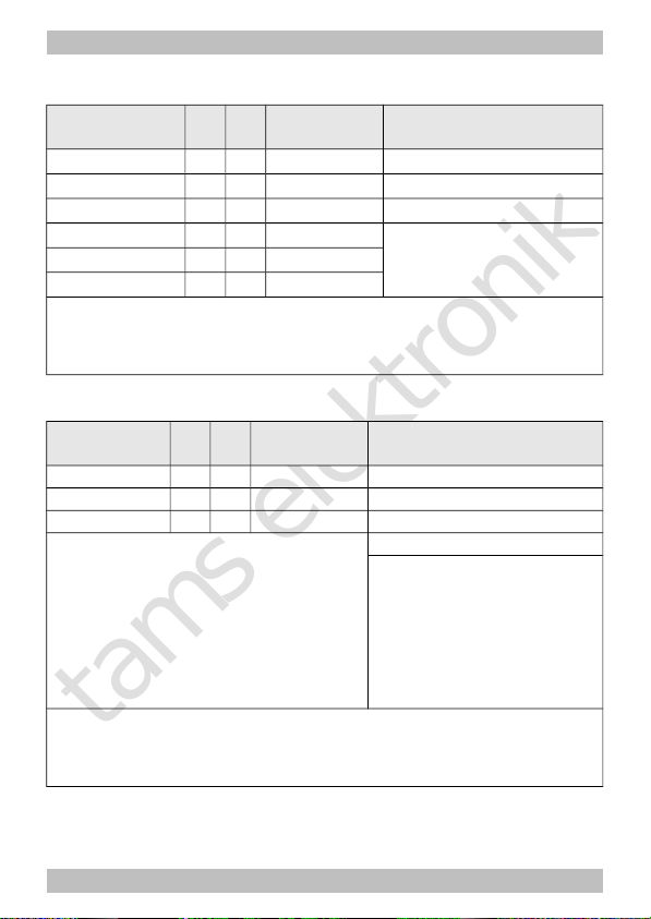
Auxiliary functions
Name of CVs /
registers
CVno.
Rgno.
Input value
(Default)
Remarks and Tips
Reset 8 03 0 ... 255 Any input value restores the
settings in state of delivery.
Auxiliary
register for
programming
with MM
central units
–- 62 1...64 (0) To enable the input of
values > 80 with central
units allowing the input of
values between 0 and 80
only.
The value set in register 62 multiplyed by 4 is added to the value of the register to be
programmed. Example for inputting the value 137 into register 09:
1. 137 / 4 = 34, remainder 1
2. Programming for register 62 the value 34.
3. Programming for register 09 the value 1.
Settings for analogue mode
Name of CVs /
registers
CVno.
Rgno.
Input value
(Default)
Remarks and Tips
Analogue
mode
12 06 0, 1 (0) = Procedure triggering a
change of direction
Overvoltage impulse
(a.c. layouts) 0
Change of polarity
(d.c. layouts) 1
iFunctions
active in
analogue
mode
(only for F1 to
F8, not for F9
to F12)
13 41 0 ... 255 (0) F1 on 1
F2 on 2
F3 on 4
F4 on 8
F5 on 16
F6 on 32
F7 on 64
F8 on 128
Page 32
Page 33
tams elektronik
LD-G-32.2 and LD-W-32.2 English
Basic settings
Name of CVs /
registers
CVno.
Rgno.
Input value
(Default)
Remarks and Tips
Configuration
data 1
29 07 0 ... 64 (14)
Direction "Standard" 0
Reverse direction 1
14 speed levels 0
28 or 128 speed levels 2
Analoge recognition off 0
Analoge recognition on 4
RailCom off 0
RailCom on 8
Linear velocity charact. 0
Alternat. velocity charact. 16
Basic addresses 0
Not for MM mode:
Extended addresses 32
Example: CV 29 = 0. à Direction = "Standard". 14 speed levels. Basic addresses. Automatic
analogue recognition = "off". RailCom = "off".
Example: CV 29 = 46. à Direction = "Standard". 28 or 128 speed levels in DCC-mode. Automatic
analogue recognition = "on". RailCom = "on". Extended addresses.
Tip: If the use of extended addresses is activated in CV 29, the decoder does not react to
signals in Motorola format!
Configuration
data 2
49 22 0 ... 255
(73)
Load control inactive 0
LD-G-32.2 only:
Load control active 1
Shunting gear at F1 2
Shunting gear at F2 4
Shunting gear at F3 8
Shunting gear at F4 16
Acceleration and brake delay
to be switched at F3 32
Acceleration and brake delay
to be switched at F4 64
Emergency stop at
change of direction off 128
Page 33
Page 34
tams elektronik
English LD-G-32.2 and LD-W-32.2
Setting the driving of the motor
Name of CVs /
registers
CVno.
Rgno.
Input value
(Default)
Remarks and Tips
Starting
voltage
(Starting
velocity)
2 47 0 … 255
(LD-G-32.2: 5)
(LD-W-32.2: 50)
= The voltage to be output
to the motor at speed level
1.
0 = 0 Volt
255 = max. voltage
Acceleration
rate
3 44 0 … 255
(LD-G-32.2 : 20)
(LD-W-32.2: 16)
= Length of the delay
before the switching to the
next higher / lower speed
level when the locomotive is
accelerating / braking.The
delay is calculated as
follows:
(value of CV 3) x 0,9 sec. /
number of speed levels
Braking rate 4 45 0 … 255
(LD-G-32.2: 15)
(LD-W-32.2: 5)
Maximum
voltage
(maximum
velocity)
5 46 0 … 255
(0)
= The voltage to be output
to the motor at the highest
speed level.
2 = 0,8 % of the max.
voltage
255 = maximum voltage
Motor
frequency
(LD-W-32.2)
9 48 0, 1 (0) =Frequency controlling the
motor
480 Hz 0
60 Hz 0
Tip: In case that the locomotive´s driving characteristics are not satisfactory with the
standard setting of 480 Hz, the motor frequency of 60 Hz should be chosen.
Page 34
Page 35
tams elektronik
LD-G-32.2 and LD-W-32.2 English
Setting the driving of the motor (continuation)
Name CV /
Register
CVNr.
Rg.
-Nr.
Eingabewert
(Defaultwert)
Erläuterungen und Hinweise
Braking
performance
with d.c.
voltage
27 49 0, 32, 64,96
(0)
No braking
with d.c. voltage 0
Braking with
negative d.c. voltage 32
Braking with
positive d.c. voltage 64
Tip: It is standard to switch over into analogue mode when applying a d.c. voltage at the
rails. In case that the decoder is run in a layout with a braking route based on applying a d.c.
voltage (e.g. Märklin**-braking route), the analogue recognition has to be disactivated (in
CV 29) to ensure that the locomotive reacts as expected on the braking route.
The setting of the negative or positive d.c. voltage is related to the right rail, as seen in the
locomotive´s direction of motion.
Starting-kick 65 62
0 … 255
(LD-G-32.2: 0)
(LD-W-32.2: 55)
= short-time increase of
motor voltage while starting
to clear the breakaway
torque
Example: CV 65 = 6 à The motor voltage while starting is equivalent to the voltage applied
in operation at speed level 6 (of 255). It is reduced immediately to the actually set speed level
with the braking rate defined in CV 4. Thus, when altering the value for CV 4 it may be
necessary to alter CV 65, too.
Alternative
velocity
characteristic
(only with
mode 28
speed levels)
68
.
.
95
68
.
.
95
0 ... 255 = velocity table for the
alternative velocity
characteristic. Any motor
voltage can be assigned to
all of the 28 speed levels.
0 = voltage of "0"
255 = maximum voltage
Page 35
Page 36
tams elektronik
English LD-G-32.2 and LD-W-32.2
Setting the load control (LD-G-32.2 only)
Name of CVs /
registers
CVno.
Rgno.
Input value
(Default)
Remarks and Tips
Parameter of
load control KP
50 23 0 ... 255 (90) = Proportional component
of the load control.
The parameter KP defines the basic speed. A too small value à locomotive too slow. A too
high value à heavy shuttering of the locomotive.
Parameter of
load control KI
51 24 0 ... 255 (70) = Integral component of
the load control.
The parameter KI provides the fine tuning of the load control. The value has to be adjusted in
very small steps. A too high value à heavy shuttering of the locomotive.
Parameter of
load control KD
52 25 0 ... 255 (40) = Differential component of
the load control.
The parameter KD retards the transforming of the load control. A too small value à
shuttering of the locomotive. A too high value à rocking of the locomotive.
Optimising the
load control
124 60 1...15 (4)
To adjust the load control to
the individual motor voltage
The value for CV 124 has to be altered when the velocity does not increase with the high
speed levels. Alter the value for CV 124 step by step until the highest velocity has just been
reached at the highest speed level.
Page 36
Page 37

tams elektronik
LD-G-32.2 and LD-W-32.2 English
Optimising the CV-settings
Above all, the driving characteristics can be influenced by setting the CV
2 (starting voltage) and CV 5 (maximum voltage) and for the decoders
for d.c.motors (LD-G-32.2), in addition, by setting the CV 124
(optimizing the load control) and the CV 50 to 52 (parameters of the
load control).
Make the setting for the load controlled decoder LD-G-32.2 in the
following order, as far as required:
1. CV 124
2. CV 50 to 52
3. CV 2 and CV 5
To adjust the parameters for the load control (CV 50 to 52) the
following procedure is recommended:
If the locomotive is shuttering: à Increase the value for CV 52 (KD) in
5-steps. If this does not lead to an improvement of the driving
characteristics, set the value of CV 52 back to factory setting (default
value). Then decrease the value for CV 50 (KP) in 5-steps and for CV 51
(KI) in 2-steps.
If the locomotive does not have enough power and e.g. gets very slow
on the way uphill: à Increase the value for CV 51 (KI) in 2-steps, until
the locomotive starts to shutter. Then increase the value for CV 52 (KD)
in 5-steps. If this does not lead to an improvement or the locomotive
starts to shutter immediately after increasing CV 51, set the values for
CV 51 and CV 52 back to factory setting (default value) and increase
the value for CV 50 (KP) in 5-steps.
If the locomotive is rocking: à Decrease the value for CV 52 in 5steps.
Page 37
Page 38
tams elektronik
English LD-G-32.2 and LD-W-32.2
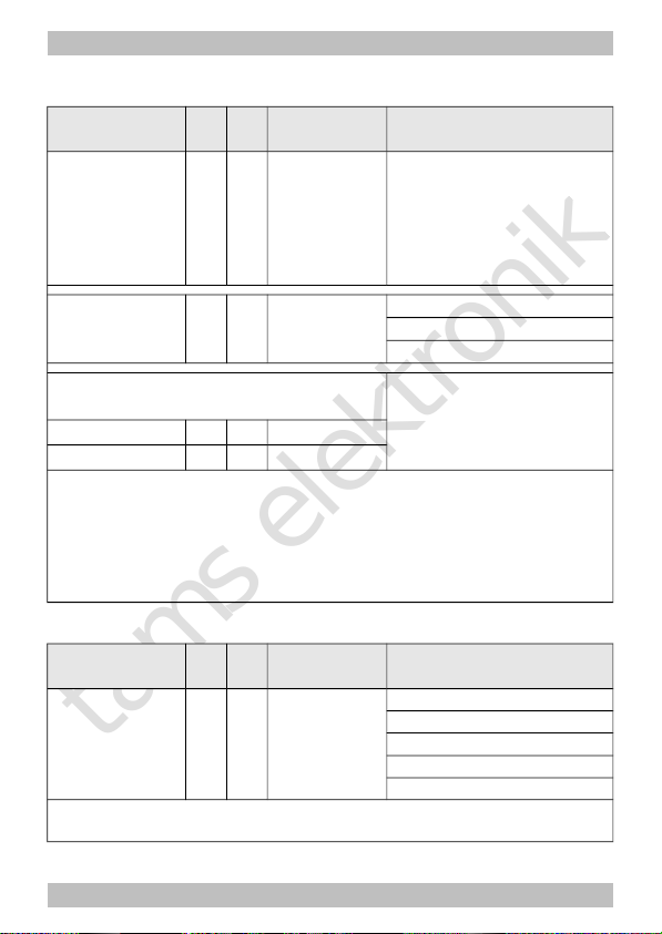
Assignment of the outputs to the function keys F0 to F12
Name of CVs /
registers
CVno.
Rgno.
Input value
(Default)
Remarks and Tips
F0 forward on 33 08 0 ... 3 (1) AUX1 1
F0 backward on 34 09 0 ... 3 (2) AUX2 2
F1 35 10 0 ... 3 (4) AUX3 4
F2 36 11 0 ... 3 (0)
... … … ...
F12 46 21 0 ... 3 (0)
Factory settings: AUX1 to be switched with F0, switched on at forward motion. AUX2 to be
switched with F0, switched on at backward motion.
Example: AUX2 to be switched with F5 à CV 39 = 2
Example: AUX1 and AUX2 to be switched with F6 à CV 40 = 3 (= 1+2)
Effects of the outputs
Name of CVs /
registers
CVno.
Rgno.
Input value
(Default)
Remarks and Tips
AUX1 53 26 0 ... 255 (0) Independent of direction 0
AUX2 54 27 0 ... 255 (0) AUX off at backw. motion 1
AUX3 55 28 0 ... 255 (0) AUX off at forward motion 2
Flashing inverted 8
Keying ratio of the flash
lights :
Lighting off 0
16, 32, 48, 64, 80, 96, 112
Regular flashing 128
144, 160, 176, 192, 208, 224
Permanent light 240
Example: Regular flashing at AUX1 and lighting off at forward motion
à CV 53 = 130 (= 128 + 2)
Tip: The keying ratio for the flash lights determines the phase length of the on-/off states of
the lighting.
Page 38
Page 39
tams elektronik
LD-G-32.2 and LD-W-32.2 English
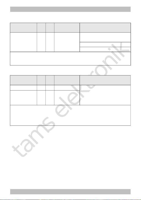
Settings for the flash lights
Name of CVs /
registers
CVno.
Rgno.
Input value
(Default)
Remarks and Tips
Flashing
frequency of
the lighting
112 38 10 ... 255
(200)
Settings common for all
lighting
10 = lowest frequency
255 = highest frequency
Examples for the flashing frequency:
CV 112 = 10 à 0,125 Hz / CV 112 = 200 à 0,5 Hz
CV 112 = 230 à 1 Hz / CV 112 = 255 à 2,5 Hz
Dimming of the outputs
Name of CVs /
registers
CVno.
Rgno.
Input value
(Default)
Remarks and Tips
AUX1, AUX2 62 35
1...255 (255) = Reduction of the voltage
applied to the output.
"1" = lowest voltage,
"255" = maximum voltage
AUX3 63 36
1...15 (15)
It is possible to choose a value between 0 and 15 for any of the outputs. For the outputs with
an odd number the value is set directly, for the outputs with an even number the input value
has to be multiplied by 16.
Example:
For AUX1 value "14" and for AUX2 value "2"à input value: 46 (=14 + 2x16)
Page 39
Page 40
tams elektronik
English LD-G-32.2 and LD-W-32.2
Dimming of the outputs depending on the speed level
Name of CVs /
registers
CVno.
Rgno.
Input value
(Default)
Remarks and Tips
Internal speed
level for CV 116
113 39 1 ... 126 (16) = speed level, from which
the outputs defined in CV
116 are dimmed with the
settings in CV 118 and 119
(instead of settings in
CV 62 and 63).
Outputs dimmed
depending on
the speed level
116 43 0 … 15 (0) AUX1 1
AUX2 2
AUX3 4
Dimming depending
on the speed level
= reduction of the voltage
at the output
"1" = lowest voltage
"255" = maximum voltage
AUX1, AUX2
118 54 1...255 (255)
AUX3
119 55 1...15 (15)
Values are applied to the outputs determined in CV 116 and starting from a speed level
determined in CV 113 only.
It is possible to choose a value between 0 and 15 for any of the outputs. For the outputs with
an odd number the value is set directly, for the outputs with an even number the input value
has to be multiplied by 16.
Example:
For AUX1 value "14" and for AUX2 value "2"à input value: 46 (=14 + 2x16)
Shunting light
Name of CVs /
registers
CVno.
Rgno.
Input value
(Default)
Remarks and Tips
Shunting light 115 42 0 ... 255 (0) for AUX1 1
for AUX2 2
for AUX3 4
to be switched with F3 64
to be switched with F4 128
Example: For AUX2 and AUX 3 shunting light, to be switched with F4:
à input value: 134 (= 2 + 4 + 128)
Page 40
Page 41

tams elektronik
!
LD-G-32.2 and LD-W-32.2 English
9. Check list for troubleshooting
Parts are getting very hot and/or start to smoke.
Disconnect the system from the mains immediately!
Possible cause: one or more connections are soldered incorrectly.
à Check the connections.
Possible cause: Short circuit between the decoder or accessories
connected to the retrun conductor for all functions and metal parts
of the locomotive or the rails. à Check the connections. A short
circuit can result in irreparable damage.
Problems with the driving characteristics
After programming the decoder the locomotive does not run or runs
badly.
Possible cause: The set values for the CV are inconsistent.
à Perform a decoder reset and program the decoder anew.
In digital mode the locomotive suddenly runs very fast.
Possible cause: Interfering signals from the layout have switched the
decoder to analogue mode. à As the origin of the interfering signals´
often cannot be found, it is advisable to switch off the automatic
recognition of the analogue mode during digital operation.
The CV values cannot be read out by RailCom.
Possible cause: RailCom is switched off. à Alter the value of CV 29
(add "8" to the input value).
Problems in analogue mode
The locomotive does not run in analogue mode, the decoder does
not work.
Possible cause: The analogue mode is switched off. Alter the
value for CV 29.
Page 41
Page 42

tams elektronik
English LD-G-32.2 and LD-W-32.2
Problems with switching of the functions
An accessory / a light does not react to switching commands.
Possible cause: The accessory is defective or incorrectly connected.
Check the accessory / the connections.
Possible cause: The output is defective (e.g. due to overload or short
circuit). Send in the decoder for check / repair (with costs).
The lighting goes on and off when the speed levels are turned up or
the lighting cannot be switched on or off.
Possible cause: The speed mode of the decoder and the digital control
unit do not correspond. Example: The central is set to the mode 28
speed levels, but the decoder to the mode 14 speed levels. Change
the speed mode at the central and / or at the decoder.
Hotline: If problems with your decoder occur, our hotline is pleased to
help you (mail address on the last page).
Repairs: You can send in a defective decoder for repair (address on
the last page). In case of guarantee the repair is free of charge for you.
With damages not covered by guarantee, the maximum fee for the
repair is 50 % of the sales price according to our valid price list. We
reserve the right to reject the repairing of a decoder when the repair is
impossible for technical or economic reasons.
Please do not send in decoders for repair charged to us. In case of
warranty we will reimburse the forwarding expenses up to the flat rate
we charge according to our valid price list for the delivery of the
product. With repairs not covered by guarantee you have to bear the
expenses for sending back and forth.
Page 42
Page 43

tams elektronik
LD-G-32.2 and LD-W-32.2 English
10. Guarantee bond
For this product we issue voluntarily a guarantee of 2 years from the
date of purchase by the first customer, but in maximum 3 years after
the end of series production. The first customer is the consumer first
purchasing the product from us, a dealer or another natural or juristic
person reselling or mounting the product on the basis of selfemployment. The guarantee exists supplementary to the legal warranty
of merchantability due to the consumer by the seller.
The warranty includes the free correction of faults which can be proved
to be due to material failure or factory flaw. With kits we guarantee
the completeness and quality of the components as well as the function
of the parts according to the parameters in not mounted state. We
guarantee the adherence to the technical specifications when the kit
has been assembled and the ready-built circuit connected according to
the manual and when start and mode of operation follow the
instructions.
We retain the right to repair, make improvements, to deliver spares or
to return the purchase price. Other claims are excluded. Claims for
secondary damages or product liability consist only according to legal
requirements.
Condition for this guarantee to be valid, is the adherence to the
manual. In addition, the guarantee claim is excluded in the following
cases:
if arbitrary changes in the circuit are made,
if repair attempts have failed with a ready-built module or device,
if damaged by other persons,
if damaged by faulty operation or by careless use or abuse.
Page 43
Page 44

tams elektronik
English LD-G-32.2 and LD-W-32.2
11. EU declaration of conformity
This product conforms with the EC-directives mentioned below
and is therefore CE certified.
2004/108/EG on electromagnetic. Underlying standards: EN 55014-1
and EN 61000-6-3. To guarantee the electromagnetic tolerance in
operation you must take the following precautions:
Connect the transformer only to an approved mains socket installed
by an authorised electrician.
Make no changes to the original parts and accurately follow the
instructions, connection diagrams and PCB layout included with this
manual.
Use only original spare parts for repairs.
2011/65/EG on the restriction of the use of certain hazardous
substances in electrical and electronic equipment (ROHS). Underlying
standard: EN 50581.
12. Declarations conforming to the WEEE directive
This product conforms with the EC-directive 2012/19/EG on
waste electrical and electronic equipment (WEEE).
Don´t dispose of this product in the house refuse, bring it to the next
recycling bay.
Page 44
Page 45

tams elektronik
LD-G-32.2 and LD-W-32.2 English
Page 45
Page 46

tams elektronik
English LD-G-32.2 and LD-W-32.2
Page 46
Page 47

tams elektronik
LD-G-32.2 and LD-W-32.2 English
Page 47
Page 48
tams elektronik
n
n
n
Information and tips:
n
http://www.tams-online.de
n
n
n
n
Warranty and service:
n
Tams Elektronik GmbH
n
Fuhrberger Straße 4
DE-30625 Hannover
n
fon: +49 (0)511 / 55 60 60
fax: +49 (0)511 / 55 61 61
n
e-mail: modellbahn@tams-online.de
n
n
 Loading...