

n
KSM-2
n
Kehrschleifenmodul
für Digitalsysteme
Loop module for digital
controlled model railways
Module de boucle de
retournement pour des
réseaux numériques
Keerlusmodule
voor digitaalsystemen
Art.-Nr. 49-01125 | 49-01126 | 49-01127 n
n
n
n
n
n
n
n
Anleitung
n
Manual
n
Mode d´emploi
n
Handleiding
n
n
n

Alle Rechte, insbesondere das Recht
der Vervielfältigung und Verbreitung
sowie der Übersetzung vorbehalten.
Vervielfältigungen und Reproduktionen in jeglicher Form bedürfen
der schriftlichen Genehmigung durch
die Tams Elektronik GmbH.
Technische Änderungen vorbehalten.
All rights reserved. No part of this
publication may be reproduced or
transmitted in any form or by any
means, electronic or mechanical,
including photocopying, without prior
permission in writing from Tams
Elektronik GmbH.
Subject to technical modification.
Tout droits réservés, en particulier les
droits de reproduction et de diffusion
ainsi que le traduction. Toute
duplication ou reproduction sous
quelque forme que ce soit nécessite
l´accord écrit de la societé Tams
Elektronik GmbH.
Sous réserve de modifications
techniques.
Alle rechten voorbehouden. Niets uit
deze publicatie mag worden
vermenig-vuldigd opgeslagen of
openbaar gemaakt, zonder voorafgaande schriftelijke toestemming van
Tams Elektronik GmbH.
Technische wijzigingen voorbehouden.
© 07/2010 Tams Elektronik GmbH
n
n
n
n
n
n
n
n
n Deutsch 3
n
English 24
n
Français 42
n
Nederlands 61
n
n
n
n

KSM-2 English
Table of contents
1. Getting started 24
2. Safety instructions 26
3. Safe and correct soldering 28
4. Operation overview 29
Diagramatic circuitry of a loop using the KSM-2 (fig. 1)
5. Technical specifications 31
6. Assembling the KSM-2 31
7. Dividing the loop into sections 36
8. Connecting the KSM-2 37
9. Check list for troubleshooting 39
10. CE and Warranty 40
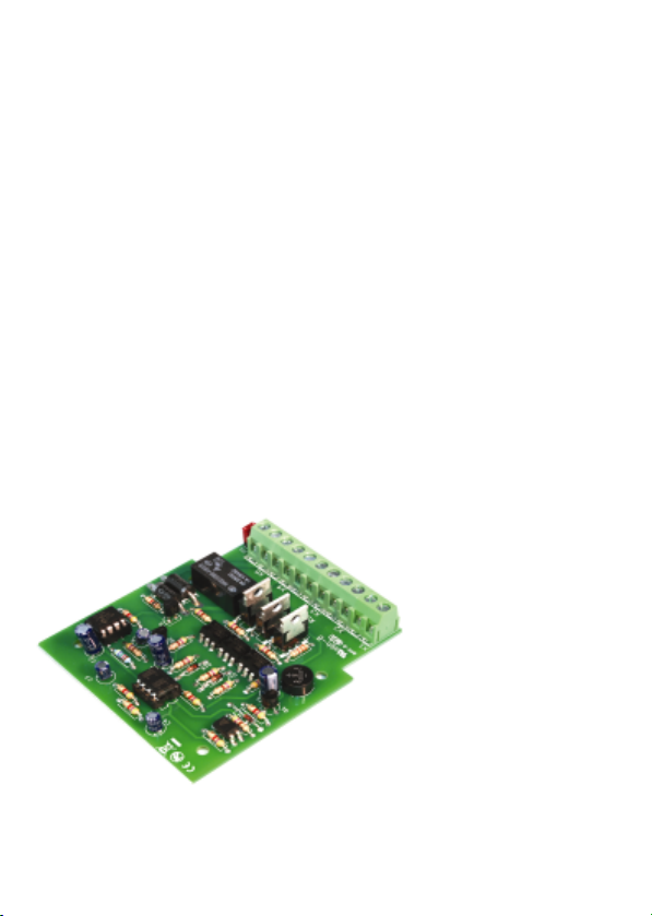
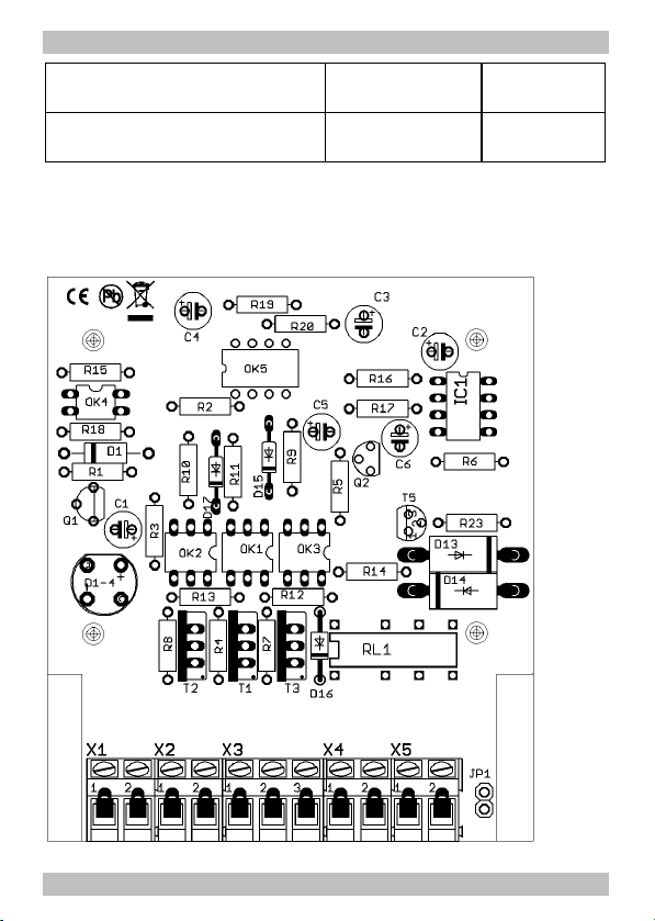
Parts list I.1
Printed Circuit Board (PCB) layout (Fig. 2) 1.2
Circuit Diagram (Fig. 3) II
Connections diagram (Fig. 4) III
(Pages I to III in the centre of this handbook are removable.)
Page 23
English KSM-2
1. Getting started
How to use this manual
This manual gives step-by-step instructions for safe and correct
assembly of the kit and fitting of the module, and operation. Before you
start, we advise you to read the whole manual, particularly the chapter
on safety instructions and the FAQ chapter. You will then know where
to take care and how to prevent mistakes which take a lot of effort to
correct.
Keep this manual safely so that you can solve problems in the future. If
you pass the kit or the module on to another person, please pass on
the manual with it.
Intended use
The loop module KSM-2 has been designed for use in digital model
railway layouts in concordance with these instructions.
Any other use is inappropriate and invalidates any guarantees.
The kit or the module should not be assembled or fitted by children
under the age of 14.
Reading, understanding and following the instructions in this manual
are mandatory for the user.
Caution:
!
The circuit contains integrated circuits. These are very sensitive to
static electricity. Do not touch components without first discharging
yourself. Touching a radiator or other grounded metal part will
discharge you.
Page 24

KSM-2 English
Checking the package contents
Please make sure that your package contains:
§ one kit, containing the components listed in the parts list and one
PCB,
§ or one ready-built module, jumper put onto JP1,
§ or one complete unit (ready-built module in a housing), jumper put
onto JP1,
§ one manual.
Required materials
For assembling the kit you need:
§ an electronic soldering iron (max. 30 Watt) with a fine tip,
§ a soldering iron stand,
§ a tip-cleaning sponge,
§ a heat-resistant mat,
§ a small side cutter and wire stripper,
§ a pair of tweezers and long nose pliers,
§ tin solder (0,5 mm. diameter),
In order to connect the module you need wire. Recommended
diameters: > 0,25 mm² for all connections.
Page 25

English KSM-2
2. Safety instructions
Mechanical hazards
Cut wires can have sharp ends and can cause serious injuries. Watch
out for sharp edges when you pick up the PCB.
Visibly damaged parts can cause unpredictable danger. Do not use
damaged parts: recycle and replace them with new ones.
Electrical hazards
§ Touching powered, live components,
§ touching conducting components which are live due to malfunction,
§ short circuits,
§ connecting the circuit to another voltage than specified,
§ impermissibly high humidity,
§ condensation build up
can cause serious injury due to electrical shock. Take the following
precautions to prevent this danger:
§ Never perform wiring on a powered module.
§ Assembling and mounting the kit should only be done in closed,
clean, dry rooms. Beware of humidity.
§ Only use low power for this module as described in this manual and
only use certified transformers.
§ Connect transformers and soldering irons only in approved mains
sockets installed by an authorised electrician.
§ Observe cable diameter requirements.
§ After condensation build up, allow a minimum of 2 hours for dispersion.
§ Use only original spare parts if you have to repair the kit or the
ready-built module.
Page 26

KSM-2 English
Fire risk
Touching flammable material with a hot soldering iron can cause fire,
which can result in injury or death through burns or suffocation.
Connect your soldering iron or soldering station only when actually
needed. Always keep the soldering iron away from inflammable
materials. Use a suitable soldering iron stand. Never leave a hot
soldering iron or station unattended.
Thermal danger
A hot soldering iron or liquid solder accidentally touching your skin can
cause skin burns. As a precaution:
§ use a heat-resistant mat during soldering,
§ always put the hot soldering iron in the soldering iron stand,
§ point the soldering iron tip carefully when soldering, and
§ remove liquid solder with a thick wet rag or wet sponge from the
soldering tip.
Dangerous environments
A working area that is too small or cramped is unsuitable and can cause
accidents, fires and injury. Prevent this by working in a clean, dry room
with enough freedom of movement.
Other dangers
Children can cause any of the accidents mentioned above because they
are inattentive and not responsible enough. Children under the age of 14
should not be allowed to work with this kit or the ready-built module.
Little children can swallow small components with sharp edges, with
fatal results! Do not allow components to reach small children.
In schools, training centres, clubs and workshops, assembly must be
supervised by qualified personnel.
In industrial institutions, health and safety regulations applying to
electronic work must be adhered to.
Page 27

English KSM-2
3. Safe and correct soldering
Caution:
!
Incorrect soldering can cause dangers through fires and heat. Avoid
these dangers by reading and following the directions given in the
chapter Safety instructions.
§ Use a small soldering iron with max. 30 Watt. Keep the soldering tip
clean so the heat of the soldering iron is applied to the solder point
effectively.
§ Only use electronic tin solder with flux.
§ When soldering electronic circuits never use soldering-water or
soldering grease. They contain acids that can corrode components
and copper tracks.
§ Solder quickly: holding the iron on the joints longer than necessary
can destroy components and can damage copper tracks or
soldering eyes.
§ Observe correct polarity orientation of semi-conductors, LEDs,
electrolytic capacitors and integrated circuits before soldering and
ensure that the solder time does not exceed 5 seconds, otherwise
components can be damaged.
§ Apply the soldering tip to the soldering spot in such a way that the part
and the soldering eye are heated at the same time. Simultaneously add
solder (not too much). As soon as the solder becomes liquid take it
away. Hold the soldering tip at the spot for a few seconds so that the
solder flows into the joint, then remove the soldering iron.
§ Do not move the component for about 5 seconds after soldering.
§ To make a good soldering joint you must use a clean and
unoxidised soldering tip. Clean the soldering tip with a damp piece
of cloth, a damp sponge or a piece of silicon cloth.
§ Cut the wires after soldering directly above the PCB solder side with
a side cutter.
Page 28

KSM-2 English
§ After placing the parts, please double check for correct polarity.
Check the PCB tracks for solder bridges and short circuits created
by accident. This would cause faulty operation or, in the worst
case, damage. You can remove excess solder by putting a clean
soldering tip on the spot. The solder will become liquid again and
flow from the soldering spot to the soldering tip.
4. Operation overview
Loop problems
At the loop points in two-rail-systems, different polarities meet with
each other. As soon as a vehicle bridges the differently polarized
sections a short circuit occurs.
Mode of operation of the KSM-2
Many loop modules work on the principle of neutralizing occuring short
circuits as quickly as possible by changing the polarity within the loop.
The loop module KSM-2 changes the polarity within the loop before a
short cicuit occurs – independently of the locomotive´s direction of
travel or the data format used to control the locomotive.
The loop module´s junctions as well as the section within the loop are
supervised by integrated track busy modules. Thus all relevant
information about the locomotive´s direction of travel and position is
given.
After the locomotive has come into one of the two junctions switched
currentless initially, the integrated track busy indicator sends a busy
message to a micro controller on the printed circuit board. As long as
only one of the two track busy indicators in the junctions indicates
"busy", the locomotive is about to drive into the loop. When the section
within the loops indicates "busy" as well, the locomotive is going to
drive out of the loop.
Page 29

English KSM-2
The micro controller controls a relay which sets the "right" polarity
within the loop. There is no short circuit occuring as the locomotive is
within the junction which initially is currentless.
After having set the polarity within the loop "properly" the two
interruptions at the initially currentless junction are closed by a switch
and the junction is supplied with current.
As a rule, the short interruption of the power supply at the
locomotive´s front axle when coming into the initially currentless
junction has no visible effects on the locomotive´s driving
characteristics.
Fig. 1: Diagramatic circuitry of a loop using the KSM-2
Track busy indicator conducted to the outside
The track busy indicator integrated into the KSM-2 which supervises the
section within the loop, is conducted to the outside of the module and
can be integrated into the rest of the layout´s control system. As they
are galvanically separated from the rest of the circuit, digital feed back
modules can be connected directly.
Page 30

KSM-2 English
Using the KSM-2 in RailCom supervised layouts
In case of supervising the loop by RailCom, the KSM-2 has a connection
for a RailCom detector. As the RailCom detector is an electric load, it
would create a permanent busy indication when connected directly to
the track section. This would invalidate the loop module´s function.
5. Technical specifications
Caution:
!
The KSM-2 should not be supplied by a transformer used for
supplying digital controlled parts of the layout!
Supply voltage 12 - 24 Volt d.c. or a.c. voltage
Current consumption (without loads) max. 100 mA
Protected to IP 00
Ambient temperature in use 0 - + 60 °C
Ambient temperature in storage -10 - + 80 °C
Comparative humidity allowed max. 85 %
Dimensions approx. 73 x 80 mm
Weight approx. 57 g
6. Assembling the KSM-2
You can skip this part if you have purchased a ready-built module or a
complete unit.
Preparation
Put the sorted components in front of you on your workbench. The
separate electronic components have the following special features you
should take into account to prevent mistakes in assembling:
Page 31

English KSM-2
Resistors
Resistors reduce current. Their mounting orientation is of no
importance. The value of resistors for smaller power ratings is
indicated through colour rings. Every colour stands for
another figure. The colour ring in brackets indicates the
tolerance of the resistor which here is of no importance.
Value Colour rings
330 Ω orange - orange - brown (gold)
470 Ω yellow - violet - brown (gold)
1 kΩ brown - black - red (gold)
4,7 kΩ yellow - violet - red (gold)
47 kΩ yellow - violet - orange (gold)
Diodes
Diodes allow the current to pass through in one direction only
(forward direction), simultaneously the voltage is reduced by
0,3 to 0,8 V. Exceeding of the limit voltage always will destroy
the diode, and allow current to flow in the reverse direction.
The diode type is printed on the body.
Diodes must be mounted in a given direction. The negative end is
marked with a ring. This is shown in the PCB layout.
Zener diodes
Zener diodes are used for limiting voltages. In contrast to "normal"
diodes they are not destroyed when the limit voltage is exceeded.
Rectifiers
Rectifiers convert alternating into direct voltage, they have
hardly no influence on the level of the voltage. They have four
pins: two for the input voltage (a.c. voltage) and two for the
output voltage (d.c. voltage). The pins for the output voltage
are polarized. The pin connections are printed on the housing.
Page 32

KSM-2 English
As usual with wired components the longer connecting pin is the
positive pole.
Electrolytic capacitors
Electrolytic capacitors are often used to store energy. In
contrast to ceramic capacitors they are polarized. One of the
two leads is marked with a minus sign which indicates the
mounting orientation. The value is given on the casing.
Electrolytic capacitors are available with different voltage
sustaining capabilities. Using an electrolytic capacitor with a
voltage sustaining capability higher than required is always
possible.
Transistors
Transistors are current amplifiers which convert low signals into
stronger ones. They have three contacts. As they are polarized, they
have to be mounted in a certain direction.
BC-Types have a housing in form of a half cylinder (SOThousing). The cross section is shown in the PCB layout which
determines the mounting orientation.
The BD types have a flat housing (TO-housing) with the type
designation printed on the front side. The metallic rear is
unlabelled, on the PCB layout the rear is marked by a thick
line.
Integrated circuits (ICs)
Depending on the type, ICs fulfil various tasks. They are
polarized and therefore have to be mounted in a certain
direction. The most common housing form is the so-called
"DIL"-housing, from which 4, 6, 8, 14, 16, 18 or more "legs"
(pins) are arranged along the long sides.
Page 33

English KSM-2
The mounting orientation is shown by a semicircular or circular marking
at the end of the housing, which is also shown on the PCB layout.
ICs are sensitive to damage during soldering (heat, electrostatic
charging). For that reason in the place of the ICs IC sockets are
soldered in, in which the ICs are inserted later. The mounting
orientation of the sockets is preset as well. The markings on the PCB,
the socket and the IC must lie on top of each other after mounting.
Micro-Controller
Micro-controller are ICs, which are individually programmed for the
particular application. When leaving the manufacturer´s works their
memory is empty. The programmed controller normally are only
available from the manufacturer of the circuit belonging to it.
Opto couplers
Opto couplers are ICs, which work similar to laser beam switches. They
combine in one housing a light emitting diode and a photo transistor.
Their task is the transmittion of information without galvanic
connection. Normally they are in a DIL-housing with 4, 6 or 8 pins.
Relays
Relays are electronic switches, depending on their position the one or
other (internal) connection is closed. Their mode of operation can be
compared to that of a push-button switch, i.e. the connection is only
closed as long as the voltage is applicated. Bistable relays keep their
status after switching – comparable to a switch.
Relays which combine two switches in one housing are common as well
(shortly 2xUM). The switching between the two connections can be
heard clearly because of the resulting clicking sound.
The mounting orientation of the relays which are put in a rectangular
box shaped housing is given by the layout of the pins.
Page 34

KSM-2 English
Terminal strips
Terminal strips are solder-in screw-type terminals. They provide a
solder-free and safe connection of the cables to the circuit, which can
still be seperated any time. When several terminal strips have to be
mounted side by side, they have to be put together before mounting.
Assembling the kit
Caution:
!
Diodes, ICs, rectifiers, transistors, electrolytic capacitors and relay
should be inserted in the right direction! If you solder them the
wrong way around the affected parts can be damaged when you
connect the power. In the worst case the whole circuit can be
damaged. At the best, a wrongly connected part will not function.
Start the assembly with the resistors and the diodes. First solder the
components on the solder side of the PCB and then cut the excess
wires with the side cutter.
Proceed with the opto coupler OK4. Solder the opto coupler OK4
directly onto the PCB (without socket).
Next solder in the IC-sockets. They have to be mounted according to
the marking on the PCB.
Continue the assembly with the rectifier, the transistors, the electrolytic
capacitors and the relay.
Next solder the terminal strips. Put together the terminal strips before
mounting them.
Finally, insert the opto couplers into the soldered IC-sockets.
Caution:
!
Do not touch the ICs without first discharging yourself by touching a
radiator or other grounded metal parts. Do not bend the "legs" of the
ICs when inserting them into the sockets. Check that the markings
on the PCB, the socket and the IC show to the same direction.
Page 35

English KSM-2
Performing a visual check
Perform a visual check after the assembly of the module and remove
faults if necessary:
§ Remove all loose parts, wire ends or drops of solder from the PCB.
Remove all sharp wire ends.
§ Check that solder contacts which are close to each other are not
unintentionally connected to each other. Risk of short circuit!
§ Check that all components are polarised correctly.
When you have remedied all faults, go on to the next part.
7. Dividing the loop into sections
Divide the loop into three sections according to fig. 4:
§ two junctions near the points and
§ the inner section of the loop.
Isolate both rails in each case. The junctions should be about half as
long as a locomotive, the inner section as long as the longest train. A
train within the loop should never bridge the junctions!
Page 36
KSM-2 English
8. Connecting the KSM-2
Follow the connections diagram fig. 4.
There are terminal strips soldered to the module which are used to
insert and screw on the connecting cables.
The assignment of the connections of the KSM-2 is as follows:
1 Track busy indicator, record output.
2 Track busy indicator, mass connection.
3, 4 Power supply (transformer).
The polarity is of no importance.
5 Outer rail in junction 1.
6 Inner rail in junctions 1 and 2.
7 Outer rail in junction 2.
8, 9 Rails outside the loop.
10 Outer rail within the loop.
11 Inner rail within the loop.
JP1 RailCom detector. Please note: In case there is no RailCom
detector to be connected, the connecting pins JP1 have to be
bridged, e.g. with the short-circuit termination (jumper)
included in the package.
Connection of the power supply
Connect the connection points 3 and 4 of the KSM-2 to a model railway
transformer. The polarity is of no importance.
Caution:
!
Do not connect the KSM-2 to the power supply of the digital system.
The occuring fault current can damage the module irreparably!
Page 37

English KSM-2
Connecting the rails
Connect the rails of the track sections according to the connection
diagram and the list to the connecting points of the KSM-2. Be sure to
connect the inner rail of both junctions to the connecting point 6.
Connection of the track busy indicator to the layout
The track busy indicator integrated into the KSM-2 which supervises the
section within the loop, is conducted to the outside of the module via
the connection points 1 and 2 and can be integrated into the rest of the
layout´s control system. The galvanic separation enables the direct
connection to digital feed back modules (e.g. s88 modules)
Connect the connecting point 1 of the KSM-2 (= record output) to the
input of the feed back module and the connecting point 2 to the mass
connection of the feed back module.
Connection of a RailCom detector
As a RailCom detector is an electric load, it would create a permanent
busy indication when connected directly to the rails within the loop. The
loop module would not work, in consequence.
The RailCom detector supervising the inner section of the loop has to
be looped in between internal track busy indicator and loop module via
the connections JP1.
As at the time of printing this manual only a few RailCom detectors are
available and future developments are pending we have refrained from
describing the connection of RailCom detectors in detail. Please contact
our technical hotline (address on the cover page) and tell us which
RailCom detector (manufacture, type) you intend to connect. You will
receive free information on connecting it then.
Attention:
!
If you do not connect a RailCom detector you have to bridge the two
connecting pins e.g. with the short circuit termination (jumper)
included in the package.
Page 38

KSM-2 English
9. Check list for troubleshooting
§ Parts are getting too hot and/or start to smoke.
Disconnect the system from the mains immediately!
!
Possible cause: one or more components are soldered incorrectly.
à In case you have mounted the module from a kit, perform a
visual check (à section 6.) and if necessary, remedy the faults.
Otherwise send in the module for repair.
§ The loop module does not work as intended.
Possible cause: There is no RailCom detector connected and the
connection points JP1 are not bridged. In consequence there are no
track busy messages to be sent from the inside of the loop.
à Bridge the connections JP1, e.g. with the short circuit
termination (jumper) included in the package.
§ When coming into the junctions a short circuit occurs.
Possible cause: The connecting points 5, 6 and 7 are not connected
to the rails of the junctions the right way.
à Check the connections, especially if the inner rails of both
junctions are connected to connecting point 6.
§ When coming into a junction the locomotive stops.
Possible cause: The connecting points 5, 6 and 7 are not properly
connected to the rails of the junctions.
à Check the connections.
Hotline: If problems with your module occur, our hotline is pleased to
help you (address on the cover page).
Repairs: You can send in a defective module for repair (address on the
cover page). In case of warranty the repair is free of charge for you.
With damages not covered by warranty, the maximum fee for the repair
is the difference between the price for the ready-built module and the
kit according to our valid price list. We reserve the right to reject the
Page 39

English KSM-2
repairing of a module when the repair is impossible for technical or
economic reasons.
Please do not send in modules for repair charged to us. In case of
warranty we will reimburse the forwarding expenses up to the flat rate
we charge according to our valid price list for the delivery of the
product. With repairs not covered by warranty you have to bear the
expenses for sending back and forth.
10. CE and Warranty
Certification (CE)
This product is developed and tested in accordance with the European
standards EN 55014-1 and EN 61000-6-3. This product conforms with
the EC-directive 2004/108/EG on electromagnetic radiation and is
therefore CE certified.
To guarantee the electromagnetic tolerance in operation you must take
the following precautions:
§ Connect the transformer only to an approved mains socket installed
by an authorised electrician.
§ Make no changes to the original parts and accurately follow the
instructions, circuit diagram and PCB layout included with this
manual.
§ Use only original spare parts if you have to repair the kit or the
ready-built module.
Conditions of warranty
This product is guaranteed for two years. The warranty includes the
correction of faults which can be proved to be due to material failure or
factory flaw.
As we have no control over the correct and proper assembly we can
only guarantee the quality of the components and the completeness of
kits. We guarantee the function of the components according to the
Page 40

KSM-2 English
parameters in not mounted state as well as the adherence to the
technical specifications of the circuit when assembled and connected
according to the manual.
Other claims are excluded. By law, we are not responsible for damages
or secondary damages in connection with this product. We retain the
right to repair, make improvements, supply spare parts or return the
purchase price.
The following invalidate the warranty:
§ using an unsuitable soldering iron, solder containing liquid acids or
similar,
§ if the kit is assembled and soldered poorly, or if damage is caused
by not following the instructions in this manual,
§ if the ready-built module has been altered and repair attempts have
failed,
§ if arbitrary changes in the circuit are made,
§ if components are removed or swapped, or wiring is added or
removed in any other way as layed down in the original design,
§ if parts other than the originals delivered with this kit are used,
§ if the copper tracks or soldering eyes are damaged,
§ when components are mounted incorrectly, or if the components or
the circuit are poled incorrectly, also subsequent damage resulting
from these faults,
§ if damage occurs due to an overload of the module,
§ if connected to a incorrect voltage or current,
§ if damaged by other persons,
§ if damaged by faulty operation or if damaged by careless use or
abuse,
§ if damaged by touching components before electrostatic
discharging of the hands.
Page 41
KSM-2
Stückliste - Parts list - Nomenclature - Stuklijst
Widerstände
Resistors
Résistances
Weerstanden
Dioden - Diodes
Zener-Dioden - Zener diodes
Diodes Zener - Zenerdiodes
Gleichrichter D1-4 B80C800
Condensers
Condensateurs
Condensatoren
ICs - ICs - CI´s - ICs
Micro-Controler IC1 PIC12F508P
Soquet IC – IC-voetje
Stiftleiste / Jumper
Solder pin / jumper
Fiche / cavalier
Pinstrip / jumper
Seite - Page - Page - Pagina I.1
R4, R7, R8 330 Ω
R5, R9, R10, R11,
R12, R13, R14,
R17, R18
R23 1 kΩ
R1, R2, R3, R6,
R15, R19, R20
R16 47 kΩ
D16 1N400x
D15, D17 1N4148
D13, D14 1N540x
D1 5V6
C3, C4, C6 2,2 µFElkos
C1, C2, C5 100 µF
T5, Q1, Q2 BC547BTransistoren - Transistors
T1, T2, T3 BT136
OK1, OK2, OK3 MOC3012M
OK4 PC817
OK5 PC827
OK1, OK2, OK3 6-pol.IC-Sockel – IC-socket
OK5, IC1 8-pol.
JP1 2-pol.
470 Ω
4,7 kΩ
Relais RL1 2xUm
monostabil
Anreihklemmen - Terminal strips
Borniers - Printkroonstenen
X1 - X5 11-pol.
Fig. 2: Bestückungsplan | PCB layout
Plan d´implantation | Printplan
KSM-2
Seite - Page - Page - Pagina I.2

KSM-2 KSM-2
Fig. 3: Schaltplan | Circuit Diagram | Schéma de principe | Schakelschema
Seite - Page - Page - Pagina II Seite - Page - Page - Pagina II

KSM-2 KSM-2
Fig. 4: Anschlussplan | Connections Diagram | Connexions | Aansluitschema
Seite - Page - Page - Pagina III Seite - Page - Page - Pagina III

n
n
n
n
Aktuelle Informationen und Tipps:
Information and tips:
Informations et conseils:
Actuele informatie en tips:
http://www.tams-online.de n
Garantie und Service:
Warranty and service:
Garantie et service:
Garantie en service:
Tams Elektronik GmbH
Rupsteinstraße 10
D-30625 Hannover
fon: +49 (0)511 / 55 60 60
fax: +49 (0)511 / 55 61 61
e-mail: modellbahn@tams-online.de
n
n
n
n
n
n
n
n
n
n
n
DE 37847206
 Loading...