

Page 1
tams elektronik
Manual
Funktionsdecoder
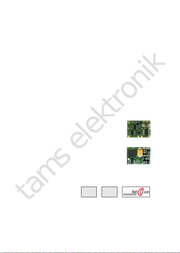
FD-R Basic.3
Item numbers 42-01180 | 42-01181
Front
Back
tams elektronik
n n n
DCC MM
Page 2

tams elektronik
English FD-R Basic.3
Contents
1. Getting started............................................................................4
2. Safety instructions.......................................................................6
3. Safe and correct soldering...........................................................9
4. Operation overview...................................................................10
4.1. Digital operation...............................................................10
4.2. Analogue mode................................................................10
4.3. Function outputs..............................................................11
4.4. Triggering the actions.......................................................14
4.5. Feedback with RailCom®...................................................14
5. Technical specifications..............................................................16
6. Connections..............................................................................17
6.1. Connector pin assignment FD-R Basic.3.............................18
6.2. Connecting accessories to the outputs...............................19
6.3. Connecting LEDs to the function outputs...........................20
6.4. Connecting inductive loads................................................22
6.5. Connecting the switching input.........................................23
6.6. Connecting a buffer capacitor/buffer circuit........................25
6.7. Fixing the decoder............................................................26
7. Programming............................................................................27
8. Configuration variables and registers..........................................29
8.1. Basic settings...................................................................30
8.2. Function mapping.............................................................31
8.3. Effects of the outputs.......................................................38
8.4. Settings for the switching input.........................................41
8.5. RailCom settings..............................................................42
Page 2
Page 3

tams elektronik
FD-R Basic.3 English
8.6. Settings for driving operation............................................43
8.7. Settings for analogue mode..............................................45
8.8. Setting the address..........................................................46
8.9. Auxiliary functions............................................................47
8.10. Information......................................................................48
9. Check list for troubleshooting.....................................................49
10. Guarantee bond........................................................................52
11. EU Declaration of Conformity.....................................................53
12. Declarations concerning the WEEE directive................................53
13. The asterisks **........................................................................54
Version 1.0 | 06/2021 | © Tams Elektronik GmbH
All rights reserved, in particular the right of reproduction, distribution
and translation. Copies, reproductions and alterations in any form
require the written permission of Tams Elektronik GmbH. We reserve
the right to make technical changes.
Printing the manual
The formatting is optimised for double-sided printing. The standard
page size is DIN A6. If you prefer a larger display, printing on DIN A5 is
recommended.
Page 3
Page 4

tams elektronik
English FD-R Basic.3
1. Getting started
How to use this manual
This manual will help you step by step to mount and commission the
decoder safely and correctly. Before you connect the decoder and put it
into operation, please read this manual completely, particularly the
chapter on safety instructions and the checklist for trouble shooting.
You will then know where to take care and how to prevent mistakes
which take a lot of effort to correct.
Keep this manual safely so that you can solve problems in the future. If
you pass the decoder on to another person, please pass on the manual
with it.
Intended use
The function decoder FD-R Basic.3 is designed to be operated
according to the instructions in this manual in model building, especially
in digital model railroad layouts. Any other use is inappropriate and
invalidates any guarantees.
The function decoder should not be mounted by children under the age
of 14.
Reading, understanding and following the instructions in this manual
are mandatory for the user.
Available versions
Connecting wires FD-R Basic.3
(item number)
without wires 42-01180
with wires
(cable length: 100 mm)
42-01181
Page 4
Page 5

tams elektronik
FD-R Basic.3 English
Checking the package contents
Please make sure that your package contains:
one or five function decoders, depending on the version with or
without soldered connecting wires.
For mounting and connecting the decoder you need:
a soldering iron with temperature control and a thin tip and a deposit
stand or a controlled soldering station
a scraper, rag or sponge
a heat-resistant pad
a small pair of side cutters and wire strippers
tweezers and flat-nose pliers if necessary
electronic solder (preferably 0.5 to 0.8 mm diameter)
In order to connect a decoder without soldered connecting wires you
will also need wire. Recommended cross sections:
> 0,04 mm² for the connections to the function outputs,
> 0,05 mm² for the connections to the current collectors or slider
To bridge short current interruptions you need:
an electrolytic capacitor with a capacity of 100 to 470 µF and a proof
voltage of minimum 25 V or
a buffer circuit, e.g.
USV-mini 0.47 (capacity 0.47 F, item no. 70-02215 or 70-02216)
USV mini 1.0 (capacity 1.0 F, item no. 70-02225 or 70-02226)
USV mini 1.5 (capacity 1.5 F, item no 70-02235 or 70-02236).
To trigger switching operations automatically, you need:
a reed contact 1 x closing contact (e.g. item-no. 84-53110) or
a Hall-sensor (e.g. item-no. 84-53210)
permanent magnets (e.g. neodymium magnets Ø 3mm, thickness
= 2 mm, item-no. 84-53990)
Page 5
Page 6

tams elektronik
!
English FD-R Basic.3
2. Safety instructions
Caution:
Integrated circuits (ICs) are inserted on the decoder. They are
sensitive to static electricity. Do not touch components without first
discharging yourself. Touching a radiator or other grounded metal part
will discharge you.
Mechanical hazards
Cut wires can have sharp ends and can cause serious injuries. Watch
out for sharp edges when you pick up the PCB.
Visibly damaged parts can cause unpredictable danger. Do not use
damaged parts: recycle and replace them with new ones.
Electrical hazards
Touching powered, live components,
touching conducting components which are live due to malfunction,
short circuits and connecting the circuit to another voltage than
specified,
impermissibly high humidity and condensation build up
can cause serious injury due to electrical shock. Take the following
precautions to prevent this danger:
Never perform wiring on a powered module.
Assembling and mounting the kit should only be done in closed,
clean, dry rooms. Beware of humidity.
Only use low power for this module as described in this manual and
only use certified transformers.
Connect transformers and soldering irons only in approved mains
sockets installed by an authorised electrician.
Observe cable diameter requirements.
After condensation build up, allow a minimum of 2 hours for dispersion.
Page 6
Page 7

tams elektronik
FD-R Basic.3 English
Use only original spare parts if you have to repair the kit or the
ready-built module.
Fire risk
Touching flammable material with a hot soldering iron can cause fire, which
can result in injury or death through burns or suffocation. Connect your
soldering iron or soldering station only when actually needed. Always keep
the soldering iron away from inflammable materials. Use a suitable
soldering iron stand. Never leave a hot soldering iron or station unattended.
Thermal danger
A hot soldering iron or liquid solder accidentally touching your skin can
cause skin burns. As a precaution:
use a heat-resistant mat during soldering,
always put the hot soldering iron in the soldering iron stand,
point the soldering iron tip carefully when soldering, and
remove liquid solder with a thick wet rag or wet sponge from the
soldering tip.
Dangerous environments
A working area that is too small or cramped is unsuitable and can cause
accidents, fires and injury. Prevent this by working in a clean, dry room
with enough freedom of movement.
Page 7
Page 8

tams elektronik
!
English FD-R Basic.3
Other dangers
Children can cause any of the accidents mentioned above because they
are inattentive and not responsible enough. Children under the age of
14 should not be allowed to mount vehicle decoders.
Caution:
Little children can swallow small components with sharp edges, with
fatal results! Do not allow components to reach small children.
In schools, training facilities, hobby and self-help workshops, the
assembly, installation and operation of electronic modules must be
supervised by trained personnel.
In commercial facilities, the relevant accident prevention regulations
must be observed.
Page 8
Page 9

tams elektronik
!
FD-R Basic.3 English
3. Safe and correct soldering
Caution:
Incorrect soldering can cause dangers through fires and heat. Avoid
these dangers by reading and following the directions given in the
chapter Safety instructions.
Use a soldering iron with temperature control, which you set to
approx. 300 °C.
Only use electronic solder with a flux.
Never use soldering fluid or soldering grease when soldering
electronic circuits. These contain an acid that destroys components
and conductor paths.
Solder quickly: Soldering for too long can detach solder pads or
tracks or even destroy components.
Hold the soldering tip on the soldering point so that it touches the
wire and the pad at the same time. Add (not too much) solder
simultaneously. As soon as the solder begins to flow, remove it from
the soldering point. Then wait a moment for the solder to flow well
before removing the soldering iron from the soldering joint.
Do not move the created solder joint for about 5 seconds.
A clean, non-oxidized soldering tip is essential for a perfect soldering
joint and good soldering. Therefore, before each soldering, wipe off
excess solder and dirt with a damp sponge, a thick damp cloth or a
silicone wiper.
After soldering, check (preferably with a magnifying glass) whether
connections or tracks have been bridged with solder by mistake. This
can lead to malfunction or destruction of components or, in the
worst case, the complete circuit. You can re-liquefy excess solder
with the clean hot soldering tip. The solder then flows from the
board onto the soldering tip.
Page 9
Page 10
tams elektronik
English FD-R Basic.3
4. Operation overview
4.1. Digital operation
The function decoder is a multiple protocol decoder, that can operate
with and automatically recognise both DCC or Motorola formats.
DCC Motorola (MM)
Number of
addresses
127 basic addresses or
10.239 extended
addresses
255
Speed level
modes
14, 28 or 128 14
Programming configuration variables
(direct programming,
DCC conform)
or POM (programming
on main = main track
programming)
registers
4.2. Analogue mode
The function decoder can also be used in analogue model railway
layouts run with an D.C. speed control, but not with an A.C. speed
control.
Automatic analogue recognition
When putting the vehicle on the rails the decoder recognizes
automatically if it is run in analogue or digital mode and sets the
corresponding operation mode. The automatic analogue recognition can
be switched off, e.g.
Page 10
Page 11

tams elektronik
FD-R Basic.3 English
if the decoder suddenly switches to analogue mode in digital
operation (e.g. as a result of interference voltages whose cause is
difficult to localise);
if a value for the Packet Time Out is programmed to perform a
forced stop in case of track voltage failure or shutdown.
Switching the function outputs
Switching the function outputs on or off is not possible in analogue
mode. The outputs can be programmed with the digital central unit so
that they are either switched on or off in analogue mode. The effects
set for the outputs are active in analogue mode as well.
Outputs that are switched depending on the direction are switched on
or off in analogue mode according to the direction of travel. When
operated in analogue d.c. layouts this applies only to lamps or accessories
where the return conductor is connected to the decoder´s common return
conductor for all function outputs.
4.3. Function outputs
The decoder has four function outputs with a maximum current of 300
mA each (F0f, F0r) or 100 mA each (AUX1, AUX2) for the connection of
additional accessories (e.g. lighting, smoke generator, electrical
coupling). Note: The maximum total current of the decoder is 700 mA.
Function mapping according to RCN-227
Assigning the functions to the outputs follows RailCommunity standard
RCN-227. It is possible to assign one or several outputs to each
function (F0 to F28, seperately for forward and backward motion for
each function). In addition, it is possible to assign another function as
an "OFF"-switch to the functions.
Page 11
Page 12

tams elektronik
English FD-R Basic.3
This mode of function mapping allows to implement special features, e.g.:
Switching on and off depending on the direction of travel.
Shunting light: When switching to shunting mode the signals for
shunting locomotive are switched on and those for standard
operation switched off.
Switching off the locomotive´s taillights when connecting wagons.
Effects of the outputs adjustable for outputs
Switching on and off depending on the
direction of travel
F0f F0r AUX1 AUX2
Shunting light F0f F0r AUX1 AUX2
Inverted switching F0f F0r AUX1 AUX2
Flashing F0f F0r AUX1 AUX2
Kick function F0f F0r AUX1 AUX2
Dimming F0f F0r AUX1 AUX2
Programming the effects
Switching depending on the direction of travel
The direction-dependent outputs are switched
over either immediately when the direction is
changed or only when speed level 0 is reached
after a change of direction.
Function Mapping
CV programming
(CV 63)
Shunting light Function Mapping
Inverted switching
When set to position "on" the assigned function
output will be switched off, when set to position
"off" switched on.
CV programming
(CV 58-60)
Page 12
Page 13

tams elektronik
FD-R Basic.3 English
Programming the effects
Flashing
By assigning the flashing function to 2 outputs
and the "inverted switching" function to one of
the two outputs, an alternating flashing is
generated.
The flashing frequency is set separately for each
output.
CV programming
(CV 58-60, CV 101-104)
Kick function
The outputs first receive full voltage for a
maximum of approx. 25.5 seconds and are then
switched off. The kick time is set separately for all
outputs.
Example of use: Some types of electrical couplings
require full voltage to decouple. However, the
voltage should be switched off after uncoupling in
order to protect the couplings.
CV programming
(CV 58-60, CV 99)
Dimming
To reduce the voltage at the output.
Example of use: The lights of older vehicles
intended for analogue operation can be dimmed
and then do not need to be replaced after the
decoder has been installed.
CV programming
(CV 47-50)
Page 13
Page 14

tams elektronik
English FD-R Basic.3
4.4. Triggering the actions
The function outputs are switched on and off and the shunting mode is
(de)activated:
through the assigned function(s) and / or
automatically via the switching input. The switching input is triggered
via external contacts, e.g. via reed contact or Hall sensors in
combination with permanent magnets in the track.
Assignment of the actions to the functions (Function Mapping)
The assignment of the actions controlled by the decoder to the
functions is freely selectable, each separately for forward and reverse
travel.
Actions
DCC format MM format
Outputs F0f, F0r, AUX1 and AUX2
F0 to F28 F0 to F4
Shunting mode (shunting light)
4.5. Feedback with RailCom
®
The function decoder FD-R Basic.3 is a RailCom transmitter and meets
the requirements of the RailCommunity standard RCN-217 "RailCom
DCC feedback protocol" (status 01.12.2019) for mobile decoders
(vehicle decoders). RCN-217 has been published on:
www.railcommunity.org
Sending RailCom messages is possible in layouts with a DCC signal on
the rails only. It is not possible to use the RailCom-function in a pure
Motorola environment.
Background information: RailCom-messages of vehicle decoders
In channel 1, the vehicle decoders transmit their DCC address after
Page 14
Page 15

tams elektronik
FD-R Basic.3 English
each DCC command directed to any vehicle decoder. Channel 1 can be
set "dynamically", i.e. the decoder will only transmit its address in
channel 1 until a DCC command is directed to it. This frees the
channel for the messages of other decoders to which no command has
yet been sent or which are not yet known to the system.
In channel 2, vehicle decoders send their feedback as soon as a DCC
command is sent to their address.
Background information: Dynamic RailCom information
"Dynamic information" mean contents of CVs (RailComCVs 64-127)
which change during operation (e.g. real speed, reception statistics,
tank content). If needed, they are sent by the decoder spontaneously.
The reception statistics are kept by the vehicle decoder, and reported
as number of faulty data packages in relation to the total number of
data packages. These statistics allow conclusions on the transmission
quality between vehicle and rails.
The function decoder FD-R Basic.3 can send the following dynamic
RailCom information:
reception statistics
RailCom® is a registered trademark of Lenz Elektronik GmbH. In order
to increase the readability of this text, we do without referring to this
with every use of the term RailCom.
Page 15
Page 16

tams elektronik
English FD-R Basic.3
5. Technical specifications
Data format DCC and MM
Feedback log RailCom
Supply voltage 12-24 Volt digital voltage
or analogue driving transformer
(max. 18 V direct voltage)
Current consumption
(without connected loads) max. max. 20 mA
Max. total current 700 mA
Number of outputs 4
Max. current / output F0f and F0r: 300 mA
AUX1 and AUX2: 100 mA
Number of inputs 1
Connection for buffer capacitor or
buffer circuit
1
Buffer capacitor Capacity: 100 to 470 µF
Proof voltage: > 15 V
Protected to IP 00
Ambient temperature in use 0 ... +60 °C
Ambient temperature in storage -10 ... +80 °C
Comparative humidity allowed max. 85 %
Dimensions PCB approx. 13 x 9,5 x 3,5 mm
Weight without wires: approx. 0,8 g
with wires: approx. 1,3 g
Page 16
Page 17

tams elektronik
!
FD-R Basic.3 English
6. Connections
Avoid irreparable damage!
Observe the following instructions to avoid damage to the decoder:
1. No conductive connections to metal parts or rails!
Avoid all conductive connections between the decoder or consumers
connected to the return conductor for all functions on the one hand,
and metal parts of the vehicle or the rails on the other hand.
Connections are caused e.g. by insufficiently insulated connecting
cables (even at the stripped ends of unused connecting cables!) or
insufficient fastening and insulation of the decoder or consumers.
Danger of short circuit!
2. Do not connect the return conductor to vehicle ground!
You should under no circumstances connect the decoder´s common
return conductor for all function outputs to vehicle ground. Risk of
short circuit!
3. Exclude overload!
Before connecting lights and additional accessories, check that the
current is below the maximum permissible values and that the total
current is not exceeded. If the permissible current is exceeded, the
decoder may be damaged during commissioning.
4. Not for use in analogue AC systems!
The FD-R Basic.3 is only approved for analogue operation with DC
driving transformers. If it is used in analogue AC systems, irreparable
damage to the components of the decoder may occur.
Page 17
Page 18

tams elektronik
English FD-R Basic.3
6.1. Connector pin assignment FD-R Basic.3
Front Back
Colour
of wire
Connection
(for use of settings in state of delivery)
Right track red Right current collector (or vehicle ground)
Left track black Left current collector (or slider)
AUX1 green AUX1 (function key F1)
AUX2 violet AUX2 (function key F2)
F0f white Lighting forward motion (function key F0)
F0r yellow Lighting backward motion (function key F0)
GND Negative pole (-) of buffer capacitor /
Earth connection IN
RC blue Common return conductor for all function
outputs (+)
Positive pole (+) of buffer capacitor
IN Switching input (back side)
Page 18
Page 19

tams elektronik
!
FD-R Basic.3 English
6.2. Connecting accessories to the outputs
Caution:
The maximum current of the accessory must not exceed the maximum
current of the output to which you connect it. The output may
otherwise be irreparably damaged!
Disconnect any existing diodes in the leads to the lamps, otherwise the
lamps might not light. Connect the lamps and the accessories to the
function outputs of the decoder. If the lamp or the accessory is already
connected with one side to vehicle ground, the connection is complete.
If not, connect the second side of the lamp or the accessory to the
decoder´s common return conductor for all function outputs.
You find the factory (default) settings in the lists with the connector pin
assignments (page 18). You can assign the outputs to the function keys
voluntarily by setting the configuration variables.
F0r: Light bulb
F0f: serial connection
of LEDs
AUX2: parallel
connection of LEDs
AUX1: combined
parallel and serial
connection of LEDs
Fig. 1: Examples for the connection of accessories and LEDs to the
function outputs
Page 19
Page 20

tams elektronik
!
English FD-R Basic.3
6.3. Connecting LEDs to the function outputs
The decoder´s function outputs switch respective to the decoder
ground. For that reason you must connect the cathodes (-) of the LEDs
to the function outputs and the anodes (+) to the decoder´s common
return conductor for all function outputs (RC).
Caution:
You must always operate LEDs via a series resistor! Otherwise LEDs will be
destroyed when put into operation or have a significantly reduced duration
of life. If you do without a series resistor, other components take over
their function (e.g. rails, wheels, current collectors). This can lead to a
change in the digital signal and thus to interference in digital operation.
Determine the required resistance value for the peak value of the
working voltage available at the return conductor (RC).
Determining the peak value of the working voltage
with regulated boosters:
output (= track) voltage of the booster - 1 V*
with not regulated boosters or analogue driving transformers:
(1,4 x the nominal voltage specified on the transformer) - 1 V*
* 1 V gets "stuck" in the rectifier of the decoder.
Serial connection of LEDs
When you want to connect several LEDs to one output you can switch them
in series via a common series resistor. The current consumption is max. 20
mA for all LEDs, depending on the series resistor´s value. The maximum
number of LEDs to be connected in series results from
Peak value of the operating voltage
- sum of the forward voltages of all LEDs
> 0
The advantage of this solution is the low current consumption.
Page 20
Page 21

tams elektronik
FD-R Basic.3 English
In order to determine the necessary series resistor for a serial LED´s
connection first add the forward voltages of all LEDs. The forward
voltages depend on the lighting colour and should be given in the
technical specifications. In case there is no manufacturer information
available, you can take as a basis 4 V for white and blue LEDs and 2 V
for yellow, orange, red and green LEDs.
The remaining voltage has to be "eliminated" by a resistor. The formula
for the calculation of the resistor is:
required RV [Ohm] = ( UB [V] – ∑ UF [V] ) / (IF [mA] x 0.001)
UB = operating voltage (peak value) | ∑ UF = sum of the forward voltages of all LEDs
IF = current with max. luminosity
Parallel connection of LEDs
Alternatively, you can connect several LEDs in parallel, each via a series
resistor of its own. The current consumption is max. 20 mA for all LEDs,
depending on the series resistor´s value. The maximum number of LEDs to
be connected in parallel results from
maximum current at the output
- sum of the current consumption of all LEDs
> 0
Advantageous with this solution is that the LEDs already lighten when
their forward voltage has been reached (2 to 4 V, depending on the
fluorescent colour), which makes this solution suitable for analogue
mode. Disadvantageous is the high current consumption.
The formula for the calculation of the resistor is:
required RV [Ohm] = ( UB [V] – UF [V] ) / (IF [mA] x 0.001)
UB = operating voltage (peak value) | UF = forward voltage of the LED
IF = current with max. luminosity
In order to save current, you can limit the LEDs´current consumption to
10 mA, which normally does not cause a visible loss of luminance.
Page 21
Page 22

tams elektronik
English FD-R Basic.3
6.4. Connecting inductive loads
When connecting inductive loads (e.g. TELEX couplings, relays or other
accessories with coils), you should switch a free-wheeling diode (e.g.
1N400x) in parallel, in order to avoid damage at the output. Check to
connect the anode of the diode to the function output.
Connecting accessories via a relay
When you want to switch an accessory / accessories via the decoder,
which connection would lead to exceeding the maximum current at the
output or of the decoder, you can switch the accessories via a relay
(e.g. 1xUm 1A 12V, item-number84-61010) and connect them directly
to the vehicle´s current collector.
The current consumed by the relay depends on its type. The relay
named in the example needs approx. 100 mA.
As described in the section "Connecting inductive loads" you should
switch a free-wheeling diode (e.g. 1N400x) in parallel to the relay.
Fig. 2: Connection
of an accessory via
a relay
Page 22
Page 23

tams elektronik
!
FD-R Basic.3 English
6.5. Connecting the switching input
The switching input switches against decoder ground and can therefore
be connected to all (external) circuits that can be used to establish a
ground connection. It is possible, for example, to connect reed contacts
or Hall sensors which establish the ground connection as soon as they
enter the magnetic field of a permanent magnet.
Connection of a reed contact
You can use both normally open contacts and changeover switches
(changeover contacts).
Note: The glass bulbs of reed contacts are sensitive to
mechanical damage!
Connect reed contacts to the switching input and the ground
connection of the decoder (GND). Reed contacts are not polarized, so
you can assign the two connections as you wish.
Fig. 3: Connection of a reed contact to the switching input
Page 23
Page 24

tams elektronik
!
English FD-R Basic.3
Connection of a Hall sensor
Pay attention to the correct polarity when connecting Hall sensors.
Assignment of the connections:
Hall sensor Decoder
Mixing up the
connections "ground
terminal" and "supply
voltage terminal" may
damage the Hall
sensor.
Ground terminal
()
Ground terminal
(GND)
Supply voltage
terminal (+)
Voltage output
(RC)
Output Switching input (IN)
Fig. 4: Connection of a Hall sensor to the switching input
Page 24
Page 25

tams elektronik
FD-R Basic.3 English
6.6. Connecting a buffer capacitor/buffer circuit
In sections with bad contact to the rails (e.g. when running over
turnouts) or with a (e.g. construction-related) bad current consumption
of the vehicle, the power supply of the decoder can be interrupted
briefly. In analogue mode the effects are usually small, but in digital
mode massive disturbances can be the result: e.g. flickering of the
lights up to automatic switching to analogue mode. This can be
remedied by connecting a backup capacitor or a special buffer circuit.
Connection of a backup capacitor
The capacitor must have a capacity of at least 100 µF and a maximum
of 470 F and a proof voltage of at least 25 V. Pay attention to the
correct polarity when connecting!
Fig. 5: Connection of a backup
capacitor ("buffer electrolytic
capacitor")
Connection of a buffer circuit
The capacity of buffer circuits is considerably larger than that of buffer
capacitors (e.g. UPS-mini with 0.47 F, 1.0 F or 1.5 F). Use a buffer
circuit according to RCN 530 that can be connected without a control
line, e.g. UPS-mini, part no. 70-0221x, 70-0222x, 70-0223x.
When connecting, follow the instructions for the buffer circuit.
Page 25
Page 26

tams elektronik
English FD-R Basic.3
6.7. Fixing the decoder
After having finished all connections you should fix the decoder, to
avoid short circuits by contact to metal parts of the vehicle, for
example. You can use double sided adhesive tape for it or a decoder
holder (item number70-01810 or 70-01820), for example.
Page 26
Page 27

tams elektronik
FD-R Basic.3 English
7. Programming
Programming with DCC central units
You can program the configuration variables (CV) of the decoder from
the digital central unit, you can use main track programming as well.
See the chapter in the manual of your central unit where the byte wise
programming of configuration variables (CVs) (Direct programming)
and main track programming (POM) are explained.
Register programming is not supported by the decoder. With DCC
central units that allow only register-programming it is not possible to
program the FD-R Basic.3.
Programming with Motorola central units
In Motorola format the settings are saved in registers. The registers
have the same numbers as the configuration variables (CVs) for the
DCC format.
Please note: If you use a central unit for both DCC and Motorola format
it is recommended to program the decoder in the DCC format. After
having finished programming the decoder it is possible to control it in
Motorola format as well.
Please note: You should connect a lamp or a LED to at least F0f or F0r
before starting to program the decoder with a Motorola central unit, as
the decoder shows the status of the programming by flashing the
lighting connected to these outputs. The flashing frequency shows,
which input the decoder expects:
Slow flashing Fast flashing
Number of the register to be
programmed
Value of the register to be
programmed
Page 27
Page 28

tams elektronik
English FD-R Basic.3
Put the vehicle on a track oval or a track section connected to the central
unit’s track output (not to the connection for the programming track).
Make sure no other vehicle than the one you intend to program is set on
the track as the decoder inside this vehicle might be programmed as well.
Starting
the programming mode
Programming the decoder
1. Switch on the central unit or
perform a reset at the central
unit (pushing "stop" and "go")
simultaneously.
2. Set the current decoder
address (default value: 3) or the
address "80".
3. Set all functions to "off".
4. Push button "stop"
→ switch off the track voltage.
5. Operate the direction switch
and hold it in that position.
Push the button "go" at once.
6. As soon as the lighting
flashes, release
the direction switch.
1. Enter the number of the
register as a Motorola-address.
If necessary: with a leading "0".
2. Operate the direction switch.
→ Lighting flashes faster.
3. Enter the value you want to
set into the register
(as Motorola-address).
4. Operate the direction switch.
→ Lighting flashes more slowly.
If necessary: repeat steps 1 to 4
for all registers to be
programmed.
Push button "stop".
→ Programming mode → End of programming mode
Programming with the Central Station I and the Mobile Station
With the Central Station I or the Mobile Station of Märklin** you can
program the registers. Select the article number 29750 from the
locomotive database and program the decoder as described for this
article in the Central Station´s or Mobile Station´s manual.
Page 28
Page 29

tams elektronik
FD-R Basic.3 English
8. Configuration variables and registers
The following lists shows all configuration variables (for the DCC
format) and registers (for the Motorola format), that can be set for the
function decoder.
Registers and configuration variables (CVs) have identical numbers,
they are shown in the tables in the column "No.". The defaults are
those values set in the state of delivery and after a reset.
Please note: With variables destined to set several parameters, the
input value has to be calculated by adding the numerical values
assigned to the desired parameters.
Page 29
Page 30

tams elektronik
English FD-R Basic.3
8.1. Basic settings
Name No. Input values
(Default)
Remarks and tips
Configuration
data 1
29 0 ... 255
(14)
Direction "Standard" 0
Reverse direction 1
14 speed levels 0
28 or 128 speed levels 2
Analogue recognition off 0
Analogue recognition on 4
RailCom off 0
RailCom on 8
Basic addresses 0
For DCC format only:
Extended addresses 32
Tip: If the use of extended addresses is
activated in CV 29, the decoder does not
react to signals in Motorola format!
Example: CV 29 = 0 → Direction = "Standard". 14 speed levels . Automatic analogue
recognition = "off". RailCom ="off". Basic addresses.
Example: CV 29 = 46 → Direction = "Standard". 28 or 128 speed levels in DCC mode.
Automatische Analogerkennung = "on". RailCom = "on". Extended addresses.
Page 30
Page 31

tams elektronik
FD-R Basic.3 English
8.2. Function mapping
The assignment of the actions controlled by the decoder
switching the function outputs on and off
(de)activation of the special function "Shunting mode / Shunting
light" (SM)
to the functions is carried out according to RailCommunity standard
RCN-227. Note: Function mapping is not possible with pure Motorola
central units.
To get access to the corresponding memory area (the so-called
"page"), the values for "Function mapping" must be set in CV 31 and 32
(= default values).
Name No. Input values
(Default)
Remarks and tips
Index for
higher pages
31 0 ... 255 (0) Function mapping 0
32 0 ... 255 (42) Function mapping 42
According to RCN-227, eight configuration variables (CVs) are assigned
to each function (F0 to F28) (four each for forward ("f") and reverse
("r"). Six of them are used for the function decoder FD-R Basic.3 (3 for
forward and 3 for reverse):
2 CVs for the outputs (F0f, F0r, AUX1 and AUX2): Here you set
which outputs are switched with the function.
1 CV for the special function "Shunting mode / Shunting light" (SM):
Here you set which function is used to activate the shunting mode.
Switch-off function: Here you can define a function with which you
can switch off the actions assigned to the function when switching
on. The value "255" determines that the actions are switched off
with no function.
Page 31
Page 32

tams elektronik
English FD-R Basic.3
Outputs
not
in use
Special
functions
off/on with
function
F0f F0r AUX1 AUX2 SM
Values
1 2 4 8 0
4
(on)
F0, F1, F2,
…, F28
Input
values
0, 1, 2, 3, 4,…, 31 0 0, 4
0, 1, 2,... 28,
255
Outputs
not
in use
Special
functions
off/on with
function
CV
name
CVNo.
Default
value
CV-
No.
Def.
value
CV-
Nr.
Def.-
wert
CVNo.
Default
value
F0 f 257
(1) F0f on during
forward travel
258 (0) 259 (0) 260 (255)
F0 r 261
(2) F0r on during
backward travel
262 (0) 263 (0) 264 (255)
F1 f 265
(4) AUX1 on during
forward travel
266 (0) 267 (0) 268 (255)
F1 r 269
(4) AUX1 on during
backward travel
270 (0) 271 (0) 272 (255)
F2 f 273
(8) AUX2 on during
forward travel
274 (0) 275 (0) 276 (255)
F2 r 277
(8) AUX2 on during
backward travel
278 (0) 279 (0) 280 (255)
F3 f 281 (0) 282 (0) 283 (4) 284 (255)
F3 r 285 (0) 286 (0) 287 (4) 288 (255)
F4 f 289 (0) 290 (0) 291 (0) 292 (255)
F4 r 293 (0) 294 (0) 295 (0) 296 (255)
F5 f 297 (0) 298 (0) 299 (0) 300 (255)
F5 r 301 (0) 302 (0) 303 (0) 304 (255)
Page 32
Page 33

tams elektronik
FD-R Basic.3 English
Outputs
not
in use
Special
functions
off/on with
function
F0f F0r AUX1 AUX2 SM
Values
1 2 4 8 0
4
(on)
F0, F1, F2,
…, F28
Input
values
0, 1, 2, 3, 4,…, 31 0 0, 4
0, 1, 2,... 28,
255
Outputs
not
in use
Special
functions
off/on with
function
CV
name
CVNo.
Default
value
CV-
No.
Def.
value
CV-
Nr.
Def.-
wert
CVNo.
Default
value
F6 f 305 (0) 306 (0) 307 (0) 308 (255)
F6 r 309 (0) 310 (0) 311 (0) 312 (255)
F7 f 313 (0) 314 (0) 315 (0) 316 (255)
F7 r 317 (0) 318 (0) 319 (0) 320 (255)
F8 f 321 (0) 322 (0) 323 (0) 324 (255)
F8 r 325 (0) 326 (0) 327 (0) 328 (255)
F9 f 329 (0) 330 (0) 331 (0) 332 (255)
F9 r 333 (0) 334 (0) 335 (0) 336 (255)
F10 f 337 (0) 338 (0) 339 (0) 340 (255)
F10 r 341 (0) 342 (0) 343 (0) 344 (255)
F11 f 345 (0) 346 (0) 347 (0) 348 (255)
F11 r 349 (0) 350 (0) 351 (0) 352 (255)
F12f 353 (0) 354 (0) 355 (0) 356 (255)
F12 r 357 (0) 358 (0) 359 (0) 360 (255)
F13 f 361 (0) 362 (0) 363 (0) 364 (255)
F13 r 365 (0) 366 (0) 367 (0) 368 (255)
Page 33
Page 34

tams elektronik
English FD-R Basic.3
Outputs
not
in use
Special
functions
off/on with
function
F0f F0r AUX1 AUX2 SM
Values
1 2 4 8 0
4
(on)
F0, F1, F2,
…, F28
Input
values
0, 1, 2, 3, 4,…, 31 0 0, 4
0, 1, 2,... 28,
255
Outputs
not
in use
Special
functions
off/on with
function
CV
name
CVNo.
Default
value
CV-
No.
Def.
value
CV-
Nr.
Def.-
wert
CVNo.
Default
value
F14 f 369 (0) 370 (0) 371 (0) 372 (255)
F14 r 373 (0) 374 (0) 375 (0) 376 (255)
F15 f 377 (0) 378 (0) 379 (0) 380 (255)
F15 r 381 (0) 382 (0) 383 (0) 384 (255)
F16 f 385 (0) 386 (0) 387 (0) 388 (255)
F16 r 389 (0) 390 (0) 391 (0) 392 (255)
F17 f 393 (0) 394 (0) 395 (0) 396 (255)
F17 r 397 (0) 398 (0) 399 (0) 400 (255)
F18 f 401 (0) 402 (0) 403 (0) 404 (255)
F18 r 405 (0) 406 (0) 407 (0) 408 (255)
F19 f 409 (0) 410 (0) 411 (0) 412 (255)
F19 r 413 (0) 414 (0) 415 (0) 416 (255)
F20 f 417 (0) 418 (0) 419 (0) 420 (255)
F20 r 421 (0) 422 (0) 423 (0) 424 (255)
F21 f 425 (0) 426 (0) 427 (0) 428 (255)
F21 r 429 (0) 430 (0) 431 (0) 432 (255)
Page 34
Page 35

tams elektronik
FD-R Basic.3 English
Outputs
not
in use
Special
functions
off/on with
function
F0f F0r AUX1 AUX2 SM
Values
1 2 4 8 0
4
(on)
F0, F1, F2,
…, F28
Input
values
0, 1, 2, 3, 4,…, 31 0 0, 4
0, 1, 2,... 28,
255
Outputs
not
in use
Special
functions
off/on with
function
CV
name
CVNo.
Default
value
CV-
No.
Def.
value
CV-
Nr.
Def.-
wert
CVNo.
Default
value
F22f 433 (0) 434 (0) 435 (0) 436 (255)
F22 r 437 (0) 438 (0) 439 (0) 440 (255)
F23 f 441 (0) 442 (0) 443 (0) 444 (255)
F23 r 445 (0) 446 (0) 447 (0) 448 (255)
F24 f 449 (0) 450 (0) 451 (0) 452 (255)
F24 r 453 (0) 454 (0) 455 (0) 456 (255)
F25 f 457 (0) 458 (0) 459 (0) 460 (255)
F25 r 461 (0) 462 (0) 463 (0) 464 (255)
F26 f 465 (0) 466 (0) 467 (0) 468 (255)
F26 r 469 (0) 470 (0) 471 (0) 472 (255)
F27 f 473 (0) 474 (0) 475 (0) 476 (255)
F27 r 477 (0) 478 (0) 479 (0) 480 (255)
F28 f 481 (0) 482 (0) 483 (0) 484 (255)
F28 r 485 (0) 486 (0) 487 (0) 488 (255)
Page 35
Page 36

tams elektronik
English FD-R Basic.3
Example: Programming for shunting operation
Hint: The connection of the return conductor is not shown.
Outputs
off/on with
function
F0f F0r 1 2
Values
1 2 4 8 1 … 254
CV
name
CV-No.
Set value
CV-No.
Set value
F0 f 257 5 (outputs F0f and AUX1) 260 3 (F3=shunting operation)
F0 r 261 10 (outputs F0r and AUX2) 264 3 (F3=shunting operation)
F3 f 265 12 (outputs AUX1 and AUX2) 268 (255 = off)
F3 r 269 12 (outputs AUX1 and AUX2) 272 (255 = off)
With this programming you achieve the following effects when
changing to shunting operation (here using function F3):
the rear end signal for the active direction of motion will be switched
off and
the three-light head end signal will be switched on on both sides.
Page 36
Page 37

tams elektronik
FD-R Basic.3 English
Example: Programming for rear end signal "off"
with coupled carriages
Hint: The connection of the return conductor is not shown.
Outputs
off/on with
function
F0f F0r 1 2
Values
1 2 4 8 1 … 254
CV
name
CV-No.
Set value
CV-No.
Set value
F0 f 257 5 (outputs F0f and AUX1) 260 5 (F5=coupled carriage)
F0 r 261 10 (outputs F0r and AUX2) 264 5 (F5=coupled carriage)
F5 f 297 4 (output AUX1) 268 (255 = off)
F5 r 301 2 ( output F0r) 272 (255 = off)
With this programming you achieve the following effects when
changing to operation with coupled carriages (here using function F5):
the signals appropriate for the direction of motion will be switched
on and
the signals on the side of the coupled carriages will be switched off.
Page 37
Page 38

tams elektronik
English FD-R Basic.3
8.3. Effects of the outputs
Assignment of the effects to the outputs
Output No. Input values
(Default)
Remarks and tips
F0f 57 0 ... 255 (0) no effects 0
F0r 58 0 ... 255 (0) Function inverted 1
AUX1 59 0 ... 255 (0)
Flashing on 2
AUX2 60 0 ... 255 (0)
Kicking on 4
Example: Alternating flashing with AUX1 and AUX2:
→ Input value for AUX1: CV 59 = 2 | Input value for AUX2: CV 60 = 3 (1 + 2)
Flashing frequency
Output No. Input values
(Default)
Remarks and tips
F0f 101 1 ... 255 (20) Setting separately for each
output.
1 = highest flashing frequency
255 = lowest flashing frequency
Note: The flashing function must be
switched on for the output.
(CV 57 - 60)
F0r 102 1 ... 255 (20)
AUX1 103 1 ... 255 (20)
AUX2 104 1 ... 255 (20)
Page 38
Page 39

tams elektronik
FD-R Basic.3 English
Kicking time
Output No. Input values
(Default)
Remarks and tips
Kicking time
("momentfunction")
99 0 ... 255
(32)
Setting common for all outputs.
0 = shortest kick time
255 = longest kick time
(= 25.5 seconds)
Increasing the input value by
"1" extends the time period by
0.1 sec.
Note: The kick function must be switched
on for the output.
(CV 57 - 60)
Dimming of the outputs
Output No. Input values
(Default)
Remarks and tips
F0f 47 1...64 (64) = Reduction of the voltage
applied to the output
1 = lowest voltage
255 = maximum voltage
F0r 48 1...64 (64)
AUX1 49
1...64 (64)
AUX2 50
1...64 (64)
Page 39
Page 40

tams elektronik
English FD-R Basic.3
Reaction to change of direction
Output No. Input values
(Default)
Remarks and tips
Change of
direction
63 0,1 (1)
Setting common for all outputs.
0 = Direction-dependent
outputs are switched
immediately when the direction
changes.
1 = Direction-dependent
outputs are only switched over
in the event of a change of
direction when speed level 0 is
reached.
Page 40
Page 41

tams elektronik
FD-R Basic.3 English
8.4. Settings for the switching input
Name No. Input values
(Default)
Remarks and tips
Assignment of
the functions
to the
switching
input
62 1 … 255 (0) F1 1
F2 2
F3 4
F4 8
F5 16
F6 32
F7 64
F8 128
Minimum
switch-on
time of the
switching
input
97 0 … 255 (0) = Time period for which the
input remains at least on after it
has been connected to ground.
Increasing the input value by
"1" extends the time period by
0.1 sec.
0 = 0 sec. (off)
255 = 25.5 sec.
Example:
The interior lighting (here switched with F1) is to be activated automatically for the duration
of the passage through a tunnel (here 10 seconds).
CV 62 = 4 (assignment of the switching input to F3)
CV 97 = 100 (= 10 seconds)
Page 41
Page 42

tams elektronik
English FD-R Basic.3
8.5. RailCom settings
Name No. Input values
(Default)
Remarks and tips
Dynamic
RailCom
information
10 0,1 (1) off 0
Reception statistics:
The decoder keeps statistics on
all DCC packets and reports the
number of faulty packets / total
number of packets in %. 1
In order to read out RailCom information, you have to make the following additional settings:
- CV 29 ("configuration data 1": RailCom on
- CV 28 "RailCom channels": at least channel 2 on
RailCom
channels
28 0 … 7
(3)
no feedback with RailCom 0
Channel 1 on 1
Channel 2 on 2
Dynamic channel 1 use 4
The setting only has an effect if channel 1
is switched on.
Please note that some RailCom detectors can only receive messages on channel 1.
For the decoder to send RailCom messages, RailCom must be switched on in CV 29.
Further information on RailCom → Section 4.5
Page 42
Page 43

tams elektronik
FD-R Basic.3 English
8.6. Settings for driving operation
Consist operation
As a standard, in multiple units (consist operation) you can only control
velocity and direction. In CV 21 and 22 you can define additional
functions to be switched when using the address for multiple units
defined in CV 19. If the value "0" is set, the function will continue to be
addressed only via the address set for the vehicle concerned in CV 1 or
CV 17 and 18.
Name No. Input values
(Default)
Remarks and tips
Functions
active in
consist
operation
(F1 to F8)
21 0 ... 255
(0)
F1 on 1
F2 on 2
F3 on 4
F4 on 8
F5 on 16
F6 on 32
F7 on 64
F8 on 128
Functions
active in
consist
operation
(F0,
F9 to F12)
22 0 ... 31
(0)
F0f on 1
F0r on 2
F9 on 4
F10 on 8
F11 on 16
F12 on 32
Page 43
Page 44

tams elektronik
English FD-R Basic.3
Setting the Packet Time Out
Name No. Input values
(Default)
Remarks and tips
Packet Time
Out
11 2 … 255
(16)
Time period between the failure
of the digital signal and the
change to the alternative
operation (analogue operation).
Increasing the input value by
"1" extends the time period by
10 ms.
Hint: If the decoder is supplied by a buffer circuit, the locomotive would continue running
unplanned after an emergency stop or a signal stop caused by switching off the track voltage.
To prevent this, you have to set a low value for the Packet Time Out (approx. 16) and switch
off the automatic switch-over to analogue operation in CV 29.
Page 44
Page 45

tams elektronik
FD-R Basic.3 English
8.7. Settings for analogue mode
Name No. Input values
(Default)
Remarks and tips
Analogue
mode
65 0, 1 (1) = Procedure triggering a change
of direction
Change of polarity
(d.c. layouts) 0
Functions
active in
analogue
mode
(F1 to F8)
13 0 … 255
(0)
F1 on 1
F2 on 2
F3 on 4
F4 on 8
F5 on 16
F6 on 32
F7 on 64
F8 on 128
Functions
active in
analogue
mode
(F0,
F9 to F12)
14 0 … 31
(0)
F0 on 1
F9 on 2
F10 on 4
F11 on 8
F12 on 16
Page 45
Page 46

tams elektronik
English FD-R Basic.3
8.8. Setting the address
Name No. Input values
(Default)
Remarks and tips
Basic address 1 1 ... 255
(3)
Range of values:
in DCC format: 1 ... 127
in MM format: 1 … 255
Tip: If a value higher than 127 is set for the basic address and the
use of extended addresses in CV 29 is set to off, the decoder does not
react to signals in DCC format!
Extended
address
17 192 ... 255
(195)
Only for DCC format.
Most central units permit
entering extended addresses
directly. The CVs 17, 18 and 29
are set automatically to the
proper values.
18 0 ... 255
(232)
Consist
address
19 1 ... 127
(0)
Address for consist operation
(multi-traction)
In DCC format only!
Page 46
Page 47

tams elektronik
FD-R Basic.3 English
8.9. Auxiliary functions
Name No. Input values
(Default)
Remarks and tips
Reset 8 0 ... 255 Any input value restores the
settings in state of delivery.
Decoder lock 15 0 ... 255 (3) Changing the CV values of the
decoder is only possible if the
values in CV 15 and 16 are
identical.
By assigning specific values in
CV 16 the CVs of decoders with
the same address can be
changed separately.
16 0 ... 255 (3)
Application e.g. for vehicles or train formations with several decoders with the same address
(e.g. locomotive, sound, function decoders).
Index for
higher
CV-Pages
31 0 (0)
Adjustable in DCC format only!
Function mapping 0
32 0 (42)
Adjustable in DCC format only!
Function mapping 42
Note: If different values are entered in CV 31 and/or 32 the function mapping for the function
outputs and special functions cannot be changed.
Page 47
Page 48

tams elektronik
English FD-R Basic.3
8.10. Information
Name No. Input values
(Default)
Remarks and tips
Version 7 ---
Read only in DCC format!
Manufacturer 8 --- (62)
Read only in DCC format!
Permitted
modes of
operation
12 --- (37)
Readable in DCC format only!
Defines the permitted modes of
operation for the decoder
FD-R Basic.3:
37 = 1 + 4 + 32
1 = DC | 4 = DCC | 32 = MM
Method for
function
assignment
96 --- (2)
Readable in DCC format only!
Defines the method for
assigning the functions:
2 = Function assignment via
CVs 257 to 512 in the bank
selected by CV 31 = 0 and
CV 32 = 42
with CVs per function
according to RailCommunity
standard RCN227 section 2
Page 48
Page 49

tams elektronik
!
FD-R Basic.3 English
9. Check list for troubleshooting
Parts are getting very hot and/or start to smoke.
Disconnect the system from the mains immediately!
Possible cause: one or more connections are soldered incorrectly.
→ Check the connections.
Possible cause: Short circuit between the decoder or accessories
connected to the retrun conductor for all functions and metal parts
of the locomotive or the rails. → Check the connections. A short
circuit can result in irreparable damage.
Problems with switching of the functions
An accessory / a light does not react to switching commands.
Possible cause: The accessory is defective or incorrectly connected.
→ Check the accessory / the connections.
Possible cause: The output is defective (e.g. due to overload or short
circuit). → Send in the decoder for check / repair (with costs).
The lighting goes on and off when the speed levels are turned up or
the lighting cannot be switched on or off.
Possible cause: The speed mode of the decoder and the digital control
unit do not correspond. Example: The central is set to the mode 28
speed levels, but the decoder to the mode 14 speed levels. → Change
the speed mode at the central and / or at the decoder.
Page 49
Page 50

tams elektronik
English FD-R Basic.3
Problems with switching via the switching input
After passing a permanent magnet in the rails no action is activated.
Possible cause: The reed contact or the Hall sensor has been
mounted incorrectly. → Check the connections.
Possible cause: The distance to the magnet is too large or the
magnet is too weak. → Alter the position of the magnet (if possible)
or use a stronger one.
Possible cause: The magnet has been mounted incorrectly polarized.
→ Alter the mounting direction.
Possible cause: The assignment of the function to the switching
input is wrong or the minimum switch-on time is too short. → Check
the inputs in CV 62 and 97.
Problems in analogue mode
The decoder does not react in analogue mode.
Possible cause: The analogue mode is switched off. → Alter the value
for CV 29.
The decoder does not switch to analogue mode (or switches over
although it is still digitally controlled).
Possible cause: The value in CV 11 is set too high or too low. → Alter
the value and check the settings in operation.
Page 50
Page 51

tams elektronik
FD-R Basic.3 English
Hotline
If problems with your decoder occur, our hotline is pleased to help you
(mail address on the last page).
Repairs
You can send in a defective decoder for repair (address on the last
page). In case of guarantee the repair is free of charge for you. With
damages not covered by guarantee, the maximum fee for the repair is
50 % of the sales price according to our valid price list. We reserve the
right to reject the repairing of a decoder when the repair is impossible
for technical or economic reasons.
Please do not send in a decoder for repair charged to us. In case of
warranty we will reimburse the forwarding expenses up to the flat rate
we charge according to our valid price list for the delivery of the
product. With repairs not covered by guarantee you have to bear the
expenses for sending back and forth.
Page 51
Page 52

tams elektronik
English FD-R Basic.3
10. Guarantee bond
For this product we issue voluntarily a guarantee of 2 years from the
date of purchase by the first customer, but in maximum 3 years after
the end of series production. The first customer is the consumer first
purchasing the product from us, a dealer or another natural or juristic
person reselling or mounting the product on the basis of selfemployment. The guarantee exists supplementary to the legal warranty
of merchantability due to the consumer by the seller.
The warranty includes the free correction of faults which can be proved
to be due to material failure or factory flaw. With kits we guarantee
the completeness and quality of the components as well as the function
of the parts according to the parameters in not mounted state. We
guarantee the adherence to the technical specifications when the kit
has been assembled and the ready-built circuit connected according to
the manual and when start and mode of operation follow the
instructions.
We retain the right to repair, make improvements, to deliver spares or
to return the purchase price. Other claims are excluded. Claims for
secondary damages or product liability consist only according to legal
requirements.
Condition for this guarantee to be valid, is the adherence to the
manual. In addition, the guarantee claim is excluded in the following
cases:
if arbitrary changes in the circuit are made,
if repair attempts have failed with a ready-built module or device,
if damaged by other persons,
if damaged by faulty operation or by careless use or abuse.
Page 52
Page 53

tams elektronik
FD-R Basic.3 English
11. EU Declaration of Conformity
This product fulfils the requirements of the following EU
directives and therefore bears the CE marking.
2001/95/EU Product Safety Directive
2015/863/EU on the restriction of the use of certain hazardous
substances in electrical and electronic equipment (RoHS)
2014/30/EU on electromagnetic compatibility (EMC Directive).
Underlying standards:
DIN-EN 55014-1 and 55014-2: Electromagnetic compatibility -
Requirements for household appliances, electric tools and similar
electrical appliances. Part 1: Emitted interference, Part 2: Immunity to
interference
To maintain electromagnetic compatibility during operation, observe
the following measures:
Only connect the supply transformer to a professionally installed and
fused earthed socket.
Do not make any changes to the original components and follow the
instructions, connection and assembly diagrams in this manual exactly.
Only use original spare parts for repair work.
12. Declarations concerning the WEEE directive
This product complies with the requirements of the EU
Directive 2012/19/EC on Waste Electrical and Electronic
Equipment (WEEE).
Do not dispose of this product in (unsorted) municipal waste, but
recycle it.
Page 53
Page 54

tams elektronik
English FD-R Basic.3
13. The asterisks **
This manual mentions the following companies:
Gebr. MÄRKLIN & Cie. GmbH | Stuttgarter Str. 55-57 | D-73033 Göppingen
Page 54
Page 55

tams elektronik
FD-R Basic.3 English
Page 55
Page 56

tams elektronik
n
n
n
Information and tips:
n
http://www.tams-online.de
n
n
n
n
Warranty and service:
n
Tams Elektronik GmbH
n
Fuhrberger Straße 4
DE-30625 Hannover
n
fon: +49 (0)511 / 55 60 60
fax: +49 (0)511 / 55 61 61
n
e-mail: modellbahn@tams-online.de
n
n
 Loading...