

Page 1

n
FD-M
n
n
n
n
Funktionsdecoder
DCC- und Motorola-Format
Function decoder
DCC- and Motorola-Format
Décodeur de fonctions
Format DCC et Motorola
Functiedecoder
DCC- en Motorola-format
Art.-Nr. 22-01-091
n
n
n
Anleitung
n
n
Manual
n
Mode d´emploi
n
Handleiding
n
n
n
n
Page 2

© 09/2007 Tams Elektronik GmbH
n
Alle Rechte, insbesondere das Recht der
Vervielfältigung und Verbreitung sowie
der Übersetzung vorbehalten. Vervielfältigungen und Reproduktionen in
jeglicher Form bedürfen der schriftlichen
Genehmigung durch die Tams Elektronik
GmbH.
Technische Änderungen vorbehalten.
All rights reserved. No part of this
publication may be reproduced or
transmitted in any form or by any
means, electronic or mechanical,
including photocopying, without prior
permission in writing from Tams
Elektronik GmbH.
Subject to technical modification.
Tout droits réservés, en particulier les
droits de reproduction et de diffusion
ainsi que le traduction. Toute duplication
ou reproduction sous quelque forme que
ce soit nécessite l´accord écrit de la
societé Tams Elektronik GmbH.
Sous réserve de modifications
techniques.
Alle rechten voorbehouden. Niets uit
deze publicatie mag worden vermenigvuldigd opgeslagen of openbaar
gemaakt, zonder voorafgaande
schriftelijke toestemming van Tams
Elektronik GmbH.
Technische wijzigingen voorbehouden.
n
n
n Deutsch 3
n English 28
n Français 53
n Nederlands 78
n
n
n
n
n
n
n
n
n
Page 3

English FD-M
Table of contents
How to use this manual 29
Intended use 29
Safety instructions 30
EMC declaration 32
Operation overview 33
Technical specifications 35
Checking the package contents 36
Required tools and materials 36
Safe and correct soldering 36
Mounting the function decoder 37
Programming the function decoder 41
Configuration variables and the registers of the FD-M 44
FAQ 49
Manufacturer's note 51
Certification 51
Conditional warranty 51
Connections (Fig. 1 and 2) I
Connection of a SUSI-module (Fig. 3) II
Circuit Diagram (Fig. 4) II
(Pages I to II in the centre of this handbook are removeable.)
Page 28
Page 4

FD-M English
!
How to use this manual
This manual gives step-by-step instructions for safe and correct fitting
of the module, and operation. Before you start, we advise you to read
the whole manual, particularly the chapter on safety instructions and
the FAQ chapter. You will then know where to take care and how to
prevent mistakes which take a lot of effort to correct.
Keep this manual safely so that you can solve problems in the future. If
you pass the module on to another person, please pass on the manual
with it.
Intended use
The function decoder is designed for mounting in a model railway
locomotive or in a model railway carriage. It evaluates the data sent to
it by the digital central unit either in DCC or Motorola format. It can
switch four amplified and one unamplified output.
The module should not be mounted or operated by children under the
age of 14.
Reading, understanding and following the instructions in this manual
are mandatory for the user.
Any other use is inappropriate and invalidates any guarantees.
Caution:
Integrated circuits (ICs) are inserted on the decoder. They are very
sensitive to static electricity. Do not touch components without first
discharging yourself. Touching a radiator or other grounded metal part
will discharge you.
Page 29
Page 5

English FD-M
Safety instructions
Mechanical hazards
Cut wires can have sharp ends and can cause serious injuries. Watch
out for sharp edges when you pick up the PCB.
Visibly damaged parts can cause unpredictable danger. Do not use
damaged parts: recycle and replace them with new ones.
Electrical hazards
§ Touching powered, live components,
§ touching conducting components which are live due to malfunction,
§ short circuits,
§ connecting the circuit to another voltage than specified,
§ impermissibly high humidity,
§ condensation build up
can cause serious injury due to electrical shock. Take the following
precautions to prevent this danger:
§ Never perform wiring on a powered module.
§ Mounting the module should only be done in closed, clean, dry
rooms. Beware of humidity.
§ Only use low power for this module as described in this manual and
only use certified transformers.
§ Connect transformers and soldering irons only in approved mains
sockets installed by an authorised electrician.
§ Observe cable diameter requirements.
§ After condensation build up, allow a minimum of 2 hours for
dispersion.
§ Use only original spare parts if you have to repair the module.
Page 30
Page 6

FD-M English
Fire risk
Touching flammable material with a hot soldering iron can cause fire,
which can result in injury or death through burns or suffocation.
Connect your soldering iron or soldering station only when actually
needed. Always keep the soldering iron away from inflammable
materials. Use a suitable soldering iron stand. Never leave a hot
soldering iron or station unattended.
Thermal danger
A hot soldering iron or liquid solder accidentally touching your skin can
cause skin burns. As a precaution:
§ use a heat-resistant mat during soldering,
§ always put the hot soldering iron in the soldering iron stand,
§ point the soldering iron tip carefully when soldering, and
§ remove liquid solder with a thick wet rag or wet sponge from the
soldering tip.
Dangerous environments
A working area that is too small or cramped is unsuitable and can cause
accidents, fires and injury. Prevent this by working in a clean, dry room
with enough freedom of movement.
Other dangers
Children can cause any of the accidents mentioned above because they
are inattentive and not responsible enough. Children under the age of
14 should not be allowed to work with this module.
Little children can swallow small components with sharp edges, with
fatal results! Do not allow components to reach small children.
In schools, training centres, clubs and workshops, assembly, mounting
and operation must be supervised by qualified personnel.
In industrial institutions, health and safety regulations applying to
electronic work must be adhered to.
Page 31
Page 7

English FD-M
EMC declaration
This product is developed and tested in accordance with the European
standards EN 55014-1 and EN 61000-6-3 and meets the EC - directive
2004/108/EG and legal requirements.
To guarantee the electromagnetic tolerance in operation you must take
the following precautions:
§ Connect the transformer only to an approved mains socket installed
by an authorised electrician.
§ Make no changes to the original parts and accurately follow the
instructions, circuit diagram and PCB layut included with this
manual.
§ Use only original spare parts if you have to repair the kit or the
ready-built module.
Page 32
Page 8

FD-M English
Operation overview
Digital Operation
The decoder FD-M is a multiple protocol decoder, that can operate with
and automatically recognises both DCC or Motorola formats.
The number of addresses is dependant on the format being used.
Motorola-Format: 255 addresses
DCC- Format: 127 Basis-addresses or 10.239 extended addresses.
In the DCC format the decoder can be driven in all speed levels (14, 28
or 128), in Motorola format only in 14 speed levels.
Programming the decoder is done in DCC format by setting the
configuration variables and in Motorola format through the registers.
Analogue mode
The decoder can also be used in analogue model railway layouts. It can be
run with an A.C. speed control as well as with a D.C. speed control. When
putting the vehicle on the rails the decoder recognizes automatically if it is
run in analogue or digital mode and sets the corresponding operation
mode. The automatic recognition of the analogue mode can be switched
off.
Switching the function outputs on or off is not possible in analogue
mode. They can be programmed so that they are either switched on or
off in analogue mode. The effects set for the outputs are active in
analogue mode as well.
Outputs to be switched with F0 are switched on or off in analogue
mode according to the direction of travel.
Page 33
Page 9

English FD-M
Function outputs
The decoder has four amplified function outputs with a maximum
current of 1.000 mA each, which are available to connect optional
accessories (e.g. lighting, smoke generator, sound module, electric
coupling) and one unamplified output with a maximum current of 10
mA. The decoder´s maximum total current is 1.500 mA.
In DCC format the function outputs can be switched via the function
keys F0 to F12. In Motorola format the function outputs can be
switched via the function keys F0 to F4. The functions F5 to F9 can be
switched via the function keys F1 to F4 and F0 by assigning them to a
second address. The functions F10 to F12 are not available in Motorola
format.
You can assign the function keys to the function outputs freely. It is
possible to assign several function keys to one function output.
SUSI interface
A SUSI module can be connected to the FD-M and programmed via the
decoder. It is not possible to read the SUSI module´s data via the
decoder.
The function decoder transmits the function status and the speed level
set at the central unit, to the SUSI module. This affects the SUSI
module´s outputs depending on the speed level (e.g. motor sound).
The FD-M allows the setting of the acceleration and braking delay so
that the functions depending on the speed level correspond to the
driving characteristics during accelerating and braking.
Effects of the function outputs
It is possible to set the following effects for all function outputs
individually:
Dimming: Example of use: The electric bulbs of older vehicles made
for analogue operation can be dimmed and thus must not be
exchanged after the mounting of the decoder.
Page 34
Page 10

FD-M English
Kick function: It is possible to set the amplified function outputs so
that they get the full voltage first for up to 20 seconds and then are
dimmed. Example of use: For some types of electric couplings you need the
full voltage for decoupling and the voltage then reduced to protect the
couplings.
Switching on and off depending on the direction of travel: This
function can be assigned either to the individual outputs or to the
function keys.
Blinken. Both the frequency and the keying ratio can be set. E.g. single
and alternating flash lights or strobe lights.
Technical specifications
Data format DCC and Motorola
Supply voltage 12-24 Volt digital voltage
Current consumption
(without connected loads) approx. 10 mA
Max. current of the
four amplified function outputs 1.000 mA each
Max. current of the
unamplified function output 10 mA
Max. total current 1.500 mA
Protected to IP 00
Ambient temperature in use 0 - + 60° C
Ambient temperature in storage -10 - + 80° C
Comparative humidity allowed max. 85 %
Dimensions approx. 23 x 12,5 x 3 mm
Weight approx. 1,05 g
Page 35
Page 11

English FD-M
Checking the package contents
Check the contents of the package for completeness immediately after
unpacking:
§ one decoder, with or without soldered connecting wires, depending
on the version.
§ one manual.
Required tools and materials
Make sure you have the following tools, equipment and materials ready
for use:
§ an electronic soldering iron (max. 30 Watt) with a fine tip,
§ a soldering iron stand,
§ a tip-cleaning sponge,
§ a heat-resistant mat,
§ a small side cutter and wire stripper,
§ a pair of tweezers,
§ tin solder (0,5 mm. diameter),
§ wire (diameter: > 0,05 mm² for all connections).
§ When the total current consumption is more than 1,0 A: a heat
sink, e.g. a SMD heat sink with a base of 7 x 19 mm.
Safe and correct soldering
Caution:
Incorrect soldering can cause dangers through fires and heat. Avoid
these dangers by reading and following the directions given in the
chapter Safety instructions.
§ Use a small soldering iron with max. 30 Watt. Keep the soldering tip
clean so the heat of the soldering iron is applied to the solder point
effectively.
Page 36
Page 12

FD-M English
§ Only use electronic tin solder with flux.
§ When soldering electronic circuits never use soldering-water or
soldering grease. They contain acids that can corrode components
and copper tracks.
§ Solder quickly: holding the iron on the joints longer than necessary
can destroy components and can damage copper tracks or
soldering eyes.
§ Apply the soldering tip to the soldering spot in such a way that the wire
and the soldering eye are heated at the same time. Simultaneously add
solder (not too much). As soon as the solder becomes liquid take it
away. Hold the soldering tip at the spot for a few seconds so that the
solder flows into the joint, then remove the soldering iron.
§ The joint should be held still for about 5 seconds after soldering.
§ To make a good soldering joint you should use a clean and
unoxidised soldering tip. Clean the soldering tip with a damp piece
of cloth, a damp sponge or a piece of silicon cloth.
§ After soldering check (preferably with a magnifying glass) tracks for
accidental solder bridges and short circuits. This would cause faulty
operation or, in the worst case, permanent damage. You can
remove excess solder by putting a clean soldering tip on the spot.
The solder will become liquid again and flow from the soldering
spot to the soldering tip.
Mounting the function decoder
Follow the connection diagrams fig. 1 and 2.
Open the vehicle´s housing. Locate the position for the decoder.
Solder the connections from the rail current collectors at the points X1
and X2. Assign the connections as follows:
X1: left rail current collector (seen in direction of motion)
X2: right rail current collector (seen in direction of motion)
Page 37
Page 13

English FD-M
Tip: It is not possible to send a confirmation signal to the central unit in
DCC format when there is not sufficient current consumption. Therefore
you should connect up at least one accessory with a minimum current
consumption of 150 to 200 mA before starting to program the decoder.
Tip: When programming the decoder with a Motorola central unit the
switch into the programming mode, and the status of the programming,
are shown by flashing the lighting connected to the outputs AUX1 to
AUX 4. You should therefore connect lighting to at least one output
before starting to program the decoder with a central unit of that kind.
Connecting accessories to the amplified outputs
Before connecting the lighting and other accessories to the amplified
outputs check if the current is below the maximum permissible value of
1.000 mA per output and the total current is below 1.500 mA. If
lighting or other accessories with current larger than 1.000 mA are
connected, or if the total current is higher than 1.500 mA the decoder
will be damaged when put into operation.
Disconnect any existing diodes in the leads to the lamps. Connect the
lamps and the accessories to the function outputs (AUX1 to AUX4) of
the decoder. The assignment of the function outputs to the function
keys will be made when programming the decoder.
If the lamp or the accessory is already connected with one side to
vehicle ground, the connection is complete. If not, connect the second
side of the lamp or the accessory to the return conductor of the
decoder (point X4).
Page 38
Page 14

FD-M English
!!!!!
!
Caution:
If you connect the accessories to the return conductor for all functions
(point X4), the accessories must be insulated. The accessories should
not make contact with metal parts of the vehicle. Possible short circuit!
The decoder will be damaged in operation.
Caution:
The return conductor for all functions (point X4) must under no
circumstances be connected to vehicle ground. Possible short circuit!
The decoder will be damaged in operation.
Decoder factory settings
If you want to use the decoder factory settings, you have to connect
the lighting and the accessories as follows:
Front lighting: AUX1
Back lighting: AUX2
Accessory switched via F1: AUX3
Accessory switched via F2: AUX4
Connecting accessories to the unamplified output
It is possible to connect an accessory with a maximum current of 10
mA (e.g. one LED) to the function output X7, or a transistor stage to
switch other accessories. Connect the input of the transistor stage to point
X7 and the emitter to point X3 (decoder ground). The output at the
collector is then amplified.
Caution:
The output X7 can be loaded with maximum 10 mA. That is suitable for
a single LED so do not try to connect lighting or other accessories.
Connecting a SUSI module
The decoder has four soldering points for the connection of a SUSI
module. You will find the pin connection in fig. 3.
Page 39
Page 15

English FD-M
!
!
Connecting the LEDs
The amplified function outputs of the decoder (AUX1 to AUX4) switch
respective to the decoder ground. For that reason you must connect
the cathode (-) of the LED to the function outputs.
When using the unamplified output (X7) connect up the LED anode (+).
As soon as the output is switched on, it is fed with 5 V.
Caution:
If you use light-emitting diodes (LEDs) you must always operate them
via a series resistor. LEDs are available in many different models. The
series resistor limits the current flow of the LED and will need to be
calculated for each model. Ask for the max. current rating when buying
your LEDs.
You can connect several LEDs in parallel to each output. In this case
every LED must have a series resistor of its own. If you connect several
LEDs to one output in series, only one series resistor is needed.
Connecting a smoothing capacitor
In track sections with bad contacts the power supply may be
interrupted shortly. You can solder a capacitor between the points X3
and X4 to conterat this effect (see fig. 1).
Fixing the decoder
After completing all connections fix the decoder with double-sided
adhesive tape, for example.
Caution:
The locomotive decoder can get warm during operation. For that
reason it should not be covered with shrinking hose or hot adhesive.
Page 40
Page 16

FD-M English
!
Caution:
When the total current consumption is more than 1,0 A you should cool
the decoder. As a heat sink you could use a SMD heat sink with a base
of 7 x 19 mm. Fix the heat sink on the diodes D1 to D4, using an
appropriate glue ( e.g. super glue ). Take care that the heat sink does not
contact the adjoining components. Risk of short circuit!
Programming the function decoder
Programming with DCC central units
You can programm the configuration variables (CV) of the decoder from
the digital central unit. See the chapter in the manual of your central
unit where the byte wise programming of configuration variables (CVs)
is explained. With central units that allow only register-programming it
is only possible to program the variables CV#1, CV#3, CV#4 and
CV#29 (= register 1, 3, 4 and 5).
Programming with the Central Station and the Mobile Station
With the Central Station or the Mobile Station of Märklin* you can
program the registers, but the value to be set is limited to 80. Select
the article no. 29750 from the locomotive database and program the
decoder as described for this article in the Central Station´s or Mobile
Station´s manual.
Programming with Motorola central units
Put the locomotive on a track oval or a track section connected to the
central unit’s track output. Make sure no other vehicle than the one you
intend to program is set on the track as the decoder inside this vehicle
might be programmed as well.
Please note: If you use a central unit for both DCC and Motorola
format it is recommended to program the decoder in the DCC format.
After having finished programming the decoder it is possible to control
it in Motorola format as well.
Page 41
Page 17

English FD-M
Starting the programming mode
Switch on the central unit or
perform a reset at the central unit.
Set the current address or address 80.
Set all functions to "off".
Push button „stop“
à Switch off the track voltage.
Operate the direction switch and hold it in
that position. Briefly push the button „go“.
As soon as the lighting flashes,
release the direction switch.
Start register-programming
(lighting flashes)
Reset the central unit (by simultaneously pushing the buttons "stop"
and "go" for some time) or quickly switch the central unit off and on. First
enter the current address or the address "80" (e.g. if you do not know the
current address). Manufacturers setting is "3". Set all functions (function,
f1 to f4) to "off".
Page 42
Page 18

FD-M English
Push the "stop" button at the central unit. Next, operate the direction
switch and hold it in that position while briefly pushing the "go" button.
As soon as the lamps connected to the outputs AUX1 to AUX4 flash
(after approx. 2 seconds) the decoder is in the programming mode and
you an release the direction switch.
After having started the programming mode (and when the
locomotive´s lighting flashes) you can program the decoder´s registers
as follows:
1. Choose the register you want to programm by setting the register´s
number with the Motorola locomotive address at your central unit.
Please note that with some central units a leading "0" has to be
entered.
2. Operate the direction switch. The lighting stops flashing.
3. Set the desired value of the register by setting the register´s value
as Motorola locomotive address at your central unit.
4. Operate the direction switch again. The lighting starts flashing
again.
Repeat the steps 1 to 4 for all registers you want to program. In order
to choose a register for programming or to enter a value for a register
you have to confirm the entered number like selecting a Motorola
locomotive address. The lighting shows which kind of entry the decoder
expects:
§ lighting flashes à entry of a CV´s number
§ lighting stops to flash à entry of a CV´s value
In order to stop the programming mode push "stop".
Page 43
Page 19
English FD-M
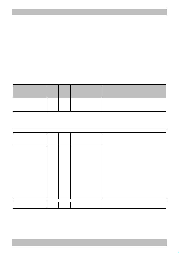
Configuration variables / Register of the FD-M
In the following list you will find in the column "CV-no." the numbers of the
configuration values for programming in DCC format and in the column
"Reg.-no." the numbers of the registers for programming in Motorola
format. The defaults are those values set in the state of delivery and after
a reset.
* For some configuration variables, the input values have to be calculated
by adding the numerical values assigned to the desired parameters.
Name of CVs /
Registers
Basic address 1 01 1 ... 255
Tip: If a value higher than 127 is set for the basic address and the use of
extended addresses in CV#29 is set to off, the decoder does not react to signals
in DCC format!
Acceleration
rate
Braking rate 4 45 0 ... 6
CV-
Reg.
Input value
no.
no.
(Default)
(3)
3 44 0 ... 6
(6)
(6)
Remarks and Tips
Range of values in
DCC-Format: 1 ... 127
= Length of the delay before
switching to the next higher
/ lower speed level. When
the vehicle is accelerating /
braking.
The value "6" corresponds to
the maximum delay. The
input value influences the
functions of the SUSI module
according to the speed.
Version 7 --- --- Read only in DCC format!
Page 44
Page 20

FD-M English
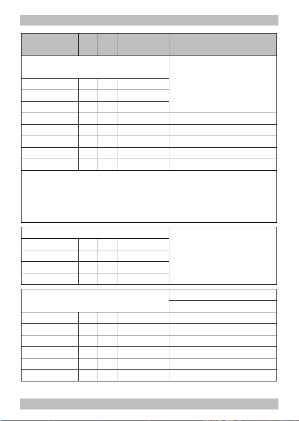
Name of CVs /
Registers
Programming
a SUSI module
CV-
Reg.
no.
no.
Input value
(Default)
Remarks and Tips
7 02 9 To start the programming of
a CV of a SUSI module. The
next CV set, is valid for the
SUSI-module. The CV-no. is
entered without a leading
"9".
Example: Programming the CV#902 of the SUSI module to the value "8":
By entering the value "9" for CV#7 of the decoder, the programming mode is
started. Next the CV of the SUSI module is chosen by entering a "2" or "02"
(leaving out the leading "9") and for the CV#902 the value "8" is set. The
decoder automatically goes back to the programming of it´s own CVs. In order
to programm another CV of the SUSI module, the operation has to be repeated
completely.
Manufacturer 8 --- (62) Read only in DCC format!
Reset 8 03 0 ... 255 Any input value restores the
settings in state of delivery.
Analogue
mode
12 06 0, 1
(0)
0 = a.c. mode
1 = d.c. mode
functions 13 41 0 ... 255 Numerical value*
active in (0) F1 on 1
analogue F2 on 2
mode F3 on 4
(only for F1 to F4 on 8
F8, not for F9 F5 on 16
to F12) F6 on 32
F7 on 64
F8 on 128
Page 45
Page 21

English FD-M
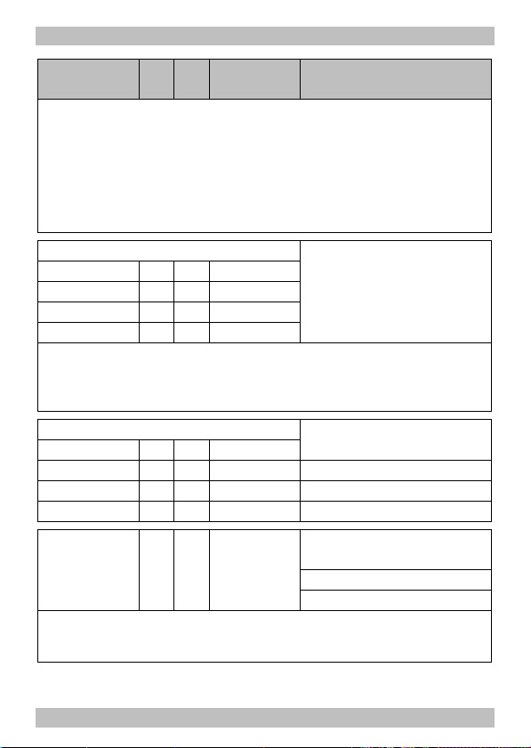
Name of CVs /
Registers
Extended
address
CV-
Reg.
Input value
no.
no.
(Default)
17 04 192 ... 255
(192)
18 05 0 ... 255
(255)
Remarks and Tips
Only for DCC format. Most
central units permit entering
extended addresses directly.
The CVs # 17, 18 and 29 are
set automatically to the
proper values.
Configuration 29 07 0 ... 64 Numerical value*
data 1 (6) Direction "Standard" 0
Reverse direction 1
14 speed levels 0
28 or 128 speed levels 2
Analoge recognition off 0
Analoge recognition on 4
Basic addresses 0
Not for MM mode: Extended addresses 32
Example: CV#29 = 0. à Direction = "Standard". 14 speed levels. Basic addresses.
Automatic analogue recognition = "off".
Example: CV#29 = 38. à Direction = "Standard". 28 or 128 speed levels in DCCmode. Extended Addresses. Automatic analogue recognition = "on".
Tip: If the use of extended addresses is activated in CV#29, the decoder does
not react to signals in Motorola format!
Page 46
Page 22
FD-M English
Name of CVs /
Registers
CVno.
Reg.
no.
Input value
(Default)
Remarks and Tips
Assignment of the function keys
to the outputs
F0 forward on 33 08 0 ... 31 (1)
F0 backward on 34 09 0 ... 31 (2) Numerical value*
F1 35 10 0 ... 31 (4) Assigned output:
F2 36 11 0 ... 31 (8) AUX1 1
F3 37 12 0 ... 31 (16) AUX2 2
F4 38 13 0 ... 31 (0) AUX3 4
... ... ... 0 ... 31 (0) AUX4 8
F12 46 21 0 ... 31 (0) X7 16
Factory settings: AUX1 to be switched with F0, switched on at forward motion.
AUX2 to be switched with F0, switched on at backward motion. AUX3 to be
switched with F1. AUX4 to be switched with F2. X7 to be switched with F3.
Example: AUX2 to be switched with F5 à CV#39 = 2
Example: AUX1 and AUX3 to be switched with F6 à CV#40 = 5 (= 1+4)
Dimming of the outputs:
AUX1 49 22 1 ... 64 (64)
AUX2 50 23 1 ... 64 (64)
AUX3 51 24 1 ... 64 (64)
AUX4 52 25 1 ... 64 (64)
= Reducing the voltage
applied to the output A.
value of "1" corresponds to
the minimum, "64" to the
maximum voltage.
Dependant on the direction of motion Numerical value*
of the outputs and function keys independent of direction 0
AUX1 / F1 53 26 0 ... 63 (0) F off at forward motion 1
AUX2 / F2 54 27 0 ... 63 (0) F off at backward motion 2
AUX3 / F3 55 28 0 ... 63 (0) AUX off at forward motion 4
AUX4 / F4 56 29 0 ... 63 (0) AUX off at backward motion 8
Shunting light AUX at F3 16
Shunting light AUX at F4 32
Page 47
Page 23
English FD-M
Name of CVs /
Registers
Factory settings: The function keys F1 to F4 switch the assigned outputs
independent of the direction of motion. The function key F0 always switches
depending on the direction of motion.
Example: Shunting light at AUX1 to be switched with F3 and at forward motion off
à CV#53 = 20 (= 16 + 4)
Example: All outputs to be switched with function key F2 at backward motion off
à CV#54 = 2
Kick function of the outputs
AUX1 57 30 1 ... 255 (0)
AUX2 58 31 1 ... 255 (0)
AUX3 59 32 1 ... 255 (0)
CVno.
Reg.
no.
Input value
(Default)
Remarks and Tips
= Setting of the period of
time after the maximum
voltage is reduced to the
dimmed value (CV# 49-52).
AUX4 60 33 1 ... 255 (0)
Increasing the input value by 8 extends the period of time by approx. 1 second.
Examples:
CV # 57-60 = 24 à Output gets the maximum voltage for approx. 3 seconds
CV # 57-60 = 80 à Output gets the maximum voltage for approx. 10 seconds
Keying ration of the flash lights = Phase´s length of the
AUX1 61 34 0...255 (255) on-/off states of the lighting
AUX2 62 35 0...255 (255) 0 à lighting off
AUX3 63 36 0...255 (255) 128à regular flashing light
AUX4 64 37 0...255 (255) 255à continuous lighting
Flashing 112 38 10 ... 255 Settings common for all
frequency of (48) lighting.
the lighting 10 à highest frequency
255à lowest frequency
Examples for the flashin frequency:
CV#112 = 10 à 2 Hz / CV#112 = 48 à 0,7 Hz
CV#112 = 100 à 0,25 Hz / CV#112 = 255 à 0,125 Hz
Page 48
Page 24
FD-M English
!
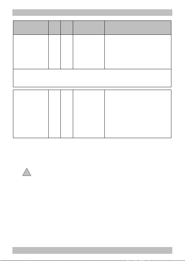
Name of CVs /
Registers
Analogue
voltage
needed for
change of
direction
Tip: In case the input value is too high, the direction of motion is not changed
with a change of direction in analogue mode. In case the value is too low,
unintended changes of direction in analoge mode can happen.
2nd Motorola
address
CV-
Reg.
Input value
no.
no.
(Default)
113 39 100 ... 200
(144)
114 40 1 ... 255
(4)
Remarks and Tips
= Value of the voltage that
has to be exceeded to
change the direction with an
analogue a.c. driving
transformer.
= Address needed to switch
additional functions in
Motorola format. The
function keys F5 to F8 are
reached via the function keys
F1 to F4, the function key F9
via the function key F0.
FAQ
§ Parts are getting very hot and/or start to smoke.
Disconnect the system from the mains immediately!
Possible cause: one or more connections are soldered incorrectly.
à Check the connections.
Possible cause: Short circuit. The decoder is connected to
locomotive or carriage ground. à Check the connections. A short
circuit can result in irreparable damage.
§ After programming, the decoder does not react as intended.
Possible cause: The set values for the CV are inconsistent.
à Perform a decoder reset and first test the decoder with the
default values. Program the decoder anew.
Page 49
Page 25

English FD-M
§ A function or an output cannot be switched on.
Possible cause: The values set in CV# 53 to 56 for a function and
an output, contradict one another. à Alter the values for CV #53 to
56.
§ The lighting does not correspond to the direction of travel.
Possible cause: The configuration data (CV29) of the locomotive
decoder in the train vary from the configuration data programmed
in the function decoder. à Change the programming or the
function or the deocder.
§ The lighting goes on and off when the speed levels are turned up
or the lighting cannot be switched on or off.
Possible cause: The speed mode of the decoder and the digital
control unit do not correspond. Example: The central is set to the
mode 28 speed levels, but the decoder to the mode 14 speed
levels. à Change the speed mode at the central and / or at the
decoder.
§ The decoder does not react in analogue mode.
Possible cause: The analogue mode is switched off. à Alter the
value for CV #29.
§ The decoder does not react to the change direction command in
analogue mode.
Possible cause: The wrong analogue mode has been defined in
CV#12. à Alter the value for CV #12.
If you cannot find the problem, please return the decoder for repair
(address on the cover page).
Page 50
Page 26

FD-M English
Manufacturer's note
The person who brings the circuit into operation is the manufacturer of
the product. If he sells the product to another person he is responsible
for passing on all the relevant papers. Domestic appliances assembled
from a kit are deemed industrial products and must comply with health
and safety regulations.
Certification
This product is developed and tested in accordance with the European
standards EN 55014-1 and EN 61000-6-3. This product conforms with
the EC- directive 2004/108/EG on electromagnetic radiation and is
therefore CE certified.
Conditions of warranty
This product is guaranteed for two years. The warranty includes the
correction of faults which can be proved to be due to material failure or
factory flaw. We guarantee the adherence to the technical
specifications of the circuit when assembled and connected according to
the manual.
Other claims are excluded. By law, we are not responsible for damages
or secondary damages in connection with this product. We retain the
right to repair, make improvements, supply spare parts or return the
purchase price.
The following invalidate the warranty:
§ using an unsuitable soldering iron, solder containing liquid acids or
similar,
§ if damage is caused by not following the instructions in this manual,
§ if the module has been altered and repair attempts have failed,
§ if arbitrary changes in the circuit are made,
§ if additional components are added which are not described in the
manual,
Page 51
Page 27

English FD-M
§ if the copper tracks or soldering eyes are damaged,
§ if damage occurs due to an overload of the module,
§ if connected to a incorrect voltage or current,
§ if damaged by other persons,
§ if damaged by faulty operation or if damaged by careless use or abuse,
§ if damaged by touching components before electrostatic
discharging of the hands.
* The following manufacturers and their products are mentioned in this
manual:
Märklin & Cie. GmbH, Goeppingen, Germany
Page 52
Page 28

FD-M FD-M
Fig. 1:
Anschluss FD-M
Connections FD-M
Connexion FD-M
Aansluiten FD-M
Fig. 2:
Anschluss der Ausgänge
an Fahrzeugmasse
Connection of the outputs
to vehicle ground
Raccordement des sorties
via la masse du vehicule
Verbining van de uitgangen
met de voortuigmassa
AUX1 bis
AUX4
X7 Unverstärkter Ausgang (max. 10 mA)
X1 Schienenabnehmer links
X2 Schienenabnehmer rechts
X3 Decodermasse
X4 Rückleiter für alle Funktionen
Verstärkte Ausgänge (max. 1.000 mA)
Amplified outputs (max. 1.000 mA)
Sorties amplifiées (max. 1.000 mA)
Versterkte uitgangen (max. 1.000 mA)
Unamplified output (max. 10 mA)
Sortie non amplifiée (max. 10 mA)
Onversterkte uitgang (max. 10 mA)
Rail current collectors left
Prises de courant de la voie gauches
Railstroomafnemers links
Rail current collectors right
Prises de courant de la voie droites
Railstroomafnemers rechts
Decoder ground
Masse du décodeur
Decodermassa
Return conductor for all functions
Pole commun des fonctions
Retourleiding voor alle functie
Elko z.B. 100 µF/35V - falls erforderlich
Elko e.g. 100 µF/35V - if necessary
Elko p.e. 100 µF/35V - si necessaire
Elko b.v. 100 µF/35V - indien noodzakelijk
LED mit Vorwiderstand
LED with series resistor
DEL avec une résistance placée en série
LED met voorschakelweerstand
Seite - Page - Page - Pagina I Seite - Page - Page - Pagina I
Page 29

FD-M FD-M
Fig. 3:
Anschluss eines SUSI-Moduls
Connection of a SUSI-module
Connexion d’un module SUSI
Aansluiten van een SUSI-module
1 SUSI – GND
(schwarz – black – noir – zwaart)
2 SUSI – DATA
(grau – grey – gris – grijs)
3 SUSI – CLK
(blau – blue – bleu – blauw)
4 SUSI – PLUS
(rot – red – rouge – rood)
Fig. 4: Schaltplan - Circuit diagram - Schéma de principe - Schakelschema
Seite - Page - Page - Pagina II Seite - Page - Page - Pagina II
Page 30

n
n
n
Aktuelle Informationen und Tipps:
Information and tips:
Informations et conseils:
Actuele informatie en tips:
http://www.tams-online.de n
Garantie und Service:
Warranty and service:
Garantie et service:
Garantie en service:
Tams Elektronik GmbH
Rupsteinstraße 10
D-30625 Hannover
fon: +49 (0)511 / 55 60 60
fax: +49 (0)511 / 55 61 61
e-mail: info@tams-online.de
n
n
n
n
n
n
n
n
n
n
n
n
 Loading...