


tams elektronik
Manual
Booster B-3
Item no. 40-19327
tams elektronik
n n n

tams elektronik
English Booster B-3
Table of contents
1. Why Boosters?............................................................................3
2. Getting started............................................................................4
3. Safety instructions.......................................................................6
4. Your B-3.....................................................................................7
5. Splitting your model railway layout.............................................11
6. Connecting the B-3....................................................................12
7. Settings....................................................................................16
8. Operation.................................................................................17
9. Check list for troubleshooting.....................................................17
10. Guarantee bond........................................................................19
11. EU declaration of conformity......................................................20
12. Declarations conforming to the WEEE directive...........................20
© 09/2016 Tams Elektronik GmbH
All rights reserved. No part of this publication may be reproduced or
transmitted in any form or by any means, electronic or mechanical,
including photocopying, without prior permission in writing from Tams
Elektronik GmbH. Subject to technical modification.
RailCom® is the registered trademark of:
Lenz Elektronik GmbH | Vogelsang 14 | DE-35398 Gießen
To increase the text´s readability we have refrained from refering to
this point in each instance.
Page 2

tams elektronik
Booster B-3 English
1. Why Boosters?
The three essential functions of boosters are:
1. Supplying the power needed for the operation of digital controlled
locomotives and points and other digital consumers.
2. Bringing the voltage to the rails, in order to make sure that all
vehicle and accessory decoders receive the digital switching and
control commands.
3. Making sure the current is switched off in case of a short-circuit on
the layout (e.g. when a vehicle derails), in order to prevent
damages at rails and vehicles.
In layouts monitored by RailCom the booster also provides the so-called
RailCom-cutout needed to transfer RailCom-feedback data.
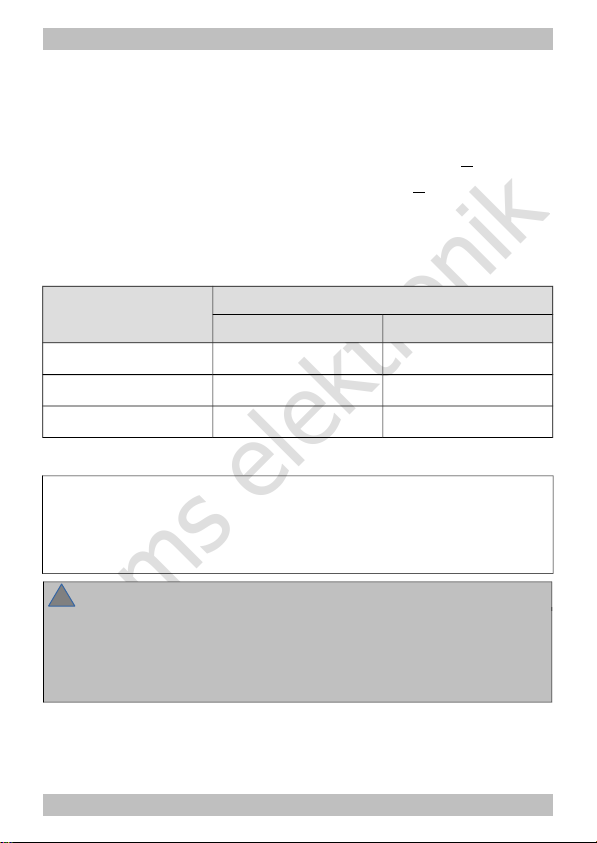
You can measure the power consumption as follows:
1 locomotive gauge N 600 mA
1 locomotive gauge H0 800 mA
1 locomotive gauge 0 1.000 mA
wagon light 50 - 200 mA
another consumer
(such as a sound module) 100 - 300 mA
reserve for points 10% of the calculated sum of
power consumption
The Booster B-3 can provide 2,5 A current. If your overall power
demand exceeds the capacity of one booster you have to connect
additional boosters according to the special requirements of your
layout.
Page 3

tams elektronik
English Booster B-3
2. Getting started
How to use this manual
This manual gives step-by-step instructions for safe and correct
connecting of the booster, and operation. Before you start, we advise
you to read the whole manual, particularly the chapter on safety
instructions and the checklist for trouble shooting. You will then know
where to take care and how to prevent mistakes which take a lot of
effort to correct.
Keep this manual safely so that you can solve problems in the future. If
you pass the booster on to another person, please pass on the manual
with it.
Intended use
The booster B-3 is designed to be operated according to the
instructions in this manual in model building, especially in digital model
railroad layouts. Any other use is inappropriate and invalidates any
guarantees.
The booster B-3 should not be mounted by children under the age of
14.
Reading, understanding and following the instructions in this manual
are mandatory for the user.
Checking the contents
Please make sure that your package contains:
Booster B-3,
one 5-pin connecting cable,
two short-circuit jumpers,
a CD (containing the manual and further information).
Page 4
tams elektronik
!
Booster B-3 English
Required materials
In order to connect the booster you need:
Wire. Recommended diameter:
for the connection to the transformer and the rails: > 1,5 mm²
for the connection to the digital control unit: > 0,25 mm²
A transformer. The recommended voltage and the minimum power
of the transformer depend on the desired settings.
Determining the necessary transformer´s voltage
Desired track voltage Recommended transformer´s voltage
AC voltage DC voltage
12 V 12 V
14 V
15 V 15 V 17 V
19 V 16 oder 18 V 21 V
Determining the transformer´s minimum power
desired track voltage x desired interrupting current
= minimum transformer´s power
Example: 19 V x 2,5 A = 47,5 VA
Please note:
Use a transformer with a nominal voltage not much higher than the
desired track voltage. The power resulting has to be dissipated as heat
by the booster otherwise. When this power is too high, the booster
overheats and switches off.
Page 5

tams elektronik
!
English Booster B-3
3. Safety instructions
Risk of fire
The booster is cooled by a heat sink to prevent overheating. Thus be
careful to allow the air to flow unhindered through the heat sink at the
booster´s back. If the airflow is blocked components can overheat and
catch fire.
Risk of electric shock
Touching powered, live components,
touching conducting components which are live due to malfunction,
short circuits and connecting the circuit to another voltage than
specified,
impermissibly high humidity and condensation build up
can cause serious injury due to electrical shock. Take the following
precautions to prevent this danger:
Only operate indoors in a dry environment.
Wiring should only be carried out when the booster is disconnected.
Only use low power for this device as described in this manual and
only use certified transformers.
Only connect the transformer in an authorised manner to the house
power supply.
Use adequetly thick cable for all wiring. Too thin a cable can
overheat.
If the layout is exposed to condensation, allow at least two hours for
drying out.
Page 6

tams elektronik
Booster B-3 English
4. Your B-3
Technical specifications
Supply voltage 12 - 20 V AC voltage or
14 – 21 V DC voltage
Maximum output current 2,5 A
Output voltage 12, 15 or 19 Volt digital voltage
Power max. 48 Watt
Digital formats DCC, Motorola,
mfx (control commands only)
Feedback log RailCom
Interfaces DCC-conforming booster port
(3-pole)
Märklin-compatible booster port
(5 pole)
Track signal symmetrical
Protected to IP 00
Ambient temperature in use 0 ... +60 °C
Ambient temperature in storage -10 ... +80 °C
Comparative humidity allowed max. 85 %
Dimensions (approx.) 100 x 90 x 35 mm
Weight (approx. ) 181 g
Page 7
tams elektronik
English Booster B-3
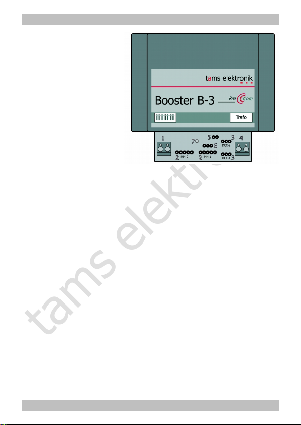
1 Track port
2 Märklin booster port
3 DCC booster port
4 Transformer port
5 RailCom
6 Track voltage
7 Operation display (LED)
Ports
The booster B-3 can be connected either to a port for a Märklincompatible booster or to a DCC-conforming booster port. Advice: The
port ( Märklin-compatible or DCC-conform) used for the booster´s
connection to the control unit, is of no importance for the data format
used to control the decoders. Use the port compatible to your control
unit.
Please note: With control units providing both booster ports (e.g. Tams
MasterControl and Tams RedBox) you have to set the short circuit
polarity according to the booster port in use.
Data formats
The booster B-3 is a multi protocol booster and capable of amplifying
data sent in the Motorola or the DCC format. It transmits control
commands in mfx-format as well, but no mfx feedback signals.
Page 8

tams elektronik
Booster B-3 English
RailCom
The booster B-3 can provide the so-called RailCom-cutout needed to
transfer RailCom-feedback data in RailCom-monitored sections.
When using the B-2 with control units sending a DCC signal but not
compatible to RailCom, providing the RailCom-cutout can cause
malfunction. Some older DCC vehicle decoders and current decoders
(especially of US American manufacturers) which are not designed for
use with Railcom, do not react to driving commands properly with the
RailCom cutout activated. With sound decoders not compatible to
RailCom interferences in the sound playback can occur.
Thus with the B-3 it is possible to switch RailCom on or off. With pure
Motorola control units, malfunction due to sending the RailCom-cutout
is impossible on principle.
Using the ABC-braking method
The booster amplifies the track signal completely symmetrically. This
allows the ABC-braking method to be used in DCC-controlled layouts.
The DCC-input of the B-3 is isolated through an opto-coupler.
Balanced track voltage
The booster B-3 provides a regulated track voltage, which can be set to
a value of 12, 15 or 19 V. At delivery the track voltage is set to 19 V.
Regulating the track voltage to a constant value prevents changes in
locomotive speeds and lighting brightness, resulting from voltage
variations.
Rated size Recommended track
voltage
Value in state of delivery
Z 12 V
N and TT 15 V
H0 19 V 19 V
Page 9

tams elektronik
English Booster B-3
Short-circuit protection
The Booster B-3 provides an intergrated short circuit breaking in shape
of an integrated current limitation. This causes the booster to switch off
automatically when a short circuit occurs at the track output and thus
prevents damages to the booster, the tracks and the vehicles. The
short circuit sensitivity or the interrupting current is set to 2,5 A.
When the short circuit feedback line is connected to the booster port of
the control unit, the B-3 sends a feedback to the control unit when a
short circuit occurs and then the control unit switches off the booster.
After approx. 5 seconds the B-3 switches on automatically. If the short
circuit is still there, it switches off again immediately. After the booster
has been switched on and off five times, the automatic switching on will
be interrupted for approx. one minute before it starts again.
Page 10
tams elektronik
Booster B-3 English
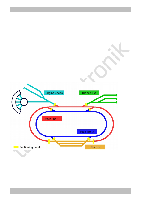
5. Splitting your model railway layout
Split your model railway layout in several track sections electrically
isolating them from each other. Every section has to be supplied by a
booster of its’ own. In each section a maximum of three to five
locomotives should run at the same time. The following divisions are
useful:
station
engine sheds
the main lines (if necessary in several sections)
the branch lines (if necessary in several sections)
Make sure that section borders are not crossed too often.
Isolate the borders between the booster sections as follows:
With 2-rail systems: one rail. Be sure to isolate in all booster sections
on the same rail ("left" or "right"). In large confusing layouts it is
recommended to isolate both rails.
With 3-rail systems: the middle conductor.
Page 11

tams elektronik
!
!
English Booster B-3
6. Connecting the B-3
Please note:
Do not block the flow of air over the heat sink at the booster´s back
surface, otherwise the booster can overheat. Risk of fire! When
connecting the booster be sure to keep sufficient distance to other
devices, walls, and the like.
Connecting the central unit
It is possible to connect the booster to
the interface of the central unit for a Märklin-compatible booster
(with a 5-pin connecting cable) or
the DCC booster interface of the central unit (with a 3-pin connecting
cable).
The enclosed cable is intended for connecting the booster to the
interface of a Märklin-compatible booster. It can be used for connecting
the booster to the central unit MasterControl. The booster configuration
of the MasterControl has to be set to "short circuit polarity: positive
(MM)" (= factory setting).
The booster B-3 has two Märklin-booster ports and two DCC-booster
ports to be used at choice. Please make sure that the pin assignment of
the central unit´s booster interface corresponds to that of the booster
port.
Please note:
When using the Märklin compatible booster port, the connection cable
between booster and control unit should not exceed a length of 1 m.
Otherwise a malfunction of the short circuit feedback can occur. When
using the DCC conform booster port it is possible to use a longer
connection cable.
Page 12
tams elektronik
Booster B-3 English
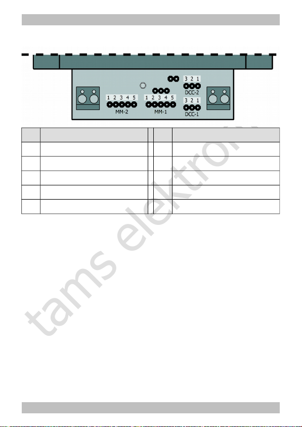
Pin assignment of the booster ports
Märklin booster port DCC booster port
1 short circuit warning wire 1 short circuit warning wire
2 earth 2 data (-)
3 direct voltage appr.+ 19 V 3 data (+)
4 booster "on / off"
5 data
Connecting an additional booster
To connect an additional booster please use the Märklin or DCC booster
port "still disengaged". Please note: If you have connected a booster
via the Märklin-compatible booster port to your central unit you have to
connect the additional booster via the "still disengaged" Märklincompatible booster port. The same goes by analogy for the DCC
booster ports.
Hint: Only use boosters of one type and made by one manufacturer to
avoid problems such as:
Problems with data transfer to the decoders.
Current leakage that make locomotives move by themselves when
other locomotives cross the borders between two track sections.
Short circuits when crossing sections.
Page 13

tams elektronik
!
!
English Booster B-3
Connecting the tracks
Connect the booster´s track port to both rails (with 2-rail systems) or to
one rail and the middle conductor (with 3-rail systems). These
connections should be repeated every 2-3 meters, because the
resistance at the connection points of the tracks is quite high. When
choosing too high intervals, problems with the short circuit indication or
the power supply of the vehicles may occur.
Please note:
The connection order of the rails (or the rail and the middle conductor)
to the two poles of the track port is not significant, if you haven’t
already connected a booster to your layout. If you have then please
note:
The left pole of the second booster´s track port has to be connected
to the same rail (or the the middle conductor) as the left pole of the
booster already connected. The same goes of course for the right pole
of the boosters´track ports. In case the connections are mixed up
short circuits will occur when vehicles cross the boundries of the track
sections.
Connecting the power supply
Connect the transformer to the booster´s transformer port. The
required voltage and the minimum power of the booster depend on the
desired track voltage. See section "required materials" on page 4.
Please note:
You must not interchange the connections to the tracks and to the
transformer. Interchanging these connections normally causes
damages at the booster, in the worst case beyond repair.
Page 14

tams elektronik
Booster B-3 English
Connection to a DCC port
Connection to a Märklin port
Page 15

tams elektronik
English Booster B-3
7. Settings
With the B-3, you can set a track voltage of 12, 15 or 19 V and switch
on or off RailCom. Position the short circuit jumpers included in the
package in concordance with the drawings to the corresponding pins on
the PCB.
Pins open
= RailCom off
Jumper inserted
= RailCom on
Jumper placed
on pin 2 and 3:
Track voltage
= 12 V
Jumper placed
on pin 1 and 2:
Track voltage
= 15 V
Pins open:
Track voltage
= 19 V
Page 16

tams elektronik
!
Booster B-3 English
8. Operation
LED
The LED on the front lights or flashes indicating the operation modes or
problems that occur.
LED Meaning
constantly lighting booster in operation
slowly flashing
(apprx. 1 sec. cycle)
no signal from the control unit
quickly flashing short circuit at the track output
Shunting the boundry between two booster sections
You should take care not to allow locomotives or trains to halt directly
on the boundary between two sections. This would lead to a connection
between the outputs and possible damaging of the two connected
boosters. The short circuit indication does not work under these
circumstances.
9. Check list for troubleshooting
The booster is getting too hot and/or starts to smoke.
Disconnect the system from the mains immediately!
Possible reason: The connections to the track and the power supply
have been mixed up. à Alter the connections. Possibly the booster
has been damaged.
The LED at the booster does not light and the locomotives cannot be
driven.
Possible reason: The power supply has been interrupted. à Check
the connections to the power supply (transformer).
Page 17

tams elektronik
English Booster B-3
The LED flashes slowly.
Possible reason: The control unit has been switched off or the
connection to the control unit has been interrupted. à Check the
control unit and the connections.
The LED flashes quickly.
Possible reason: There is a short circuit at the track output.
Therefore the booster switches off automatically and after approx. 5
seconds automatically on again. In case the short circuit is still there
after autostarting, the booster switches off immediately. This
procedure is repeated five times, followed by a one minute break.
à Eliminate the short circuit.
Hotline
If problems with your device occur, our hotline is pleased to help you
(mail address on the last page).
Repairs
You can send in a defective device for repair (address on the last
page). In case of guarantee the repair is free of charge for you. With
damages not covered by guarantee, the maximum fee for the repair is
50 % of the sales price according to our valid price list. We reserve the
right to reject the repairing of a device when the repair is impossible for
technical or economic reasons.
Please do not send in devices for repair charged to us. In case of
warranty we will reimburse the forwarding expenses up to the flat rate
we charge according to our valid price list for the delivery of the
product. With repairs not covered by guarantee you have to bear the
expenses for sending back and forth.
Page 18

tams elektronik
Booster B-3 English
10. Guarantee bond
For this product we issue voluntarily a guarantee of 2 years from the
date of purchase by the first customer, but in maximum 3 years after
the end of series production. The first customer is the consumer first
purchasing the product from us, a dealer or another natural or juristic
person reselling or mounting the product on the basis of selfemployment. The guarantee exists supplementary to the legal warranty
of merchantability due to the consumer by the seller.
The warranty includes the free correction of faults which can be proved
to be due to material failure or factory flaw. With kits we guarantee
the completeness and quality of the components as well as the function
of the parts according to the parameters in not mounted state. We
guarantee the adherence to the technical specifications when the kit
has been assembled and the ready-built circuit connected according to
the manual and when start and mode of operation follow the
instructions.
We retain the right to repair, make improvements, to deliver spares or
to return the purchase price. Other claims are excluded. Claims for
secondary damages or product liability consist only according to legal
requirements.
Condition for this guarantee to be valid, is the adherence to the
manual. In addition, the guarantee claim is excluded in the following
cases:
if arbitrary changes in the circuit are made,
if repair attempts have failed with a ready-built module or device,
if damaged by other persons,
if damaged by faulty operation or by careless use or abuse.
Page 19

tams elektronik
English Booster B-3
11. EU declaration of conformity
This product conforms with the EC-directives mentioned below
and is therefore CE certified.
2004/108/EG on electromagnetic. Underlying standards: EN 55014-1
and EN 61000-6-3. To guarantee the electromagnetic tolerance in
operation you must take the following precautions:
Connect the transformer only to an approved mains socket installed
by an authorised electrician.
Make no changes to the original parts and accurately follow the
instructions, connection diagrams and PCB layout included with this
manual.
Use only original spare parts for repairs.
2011/65/EG on the restriction of the use of certain hazardous
substances in electrical and electronic equipment (ROHS). Underlying
standard: EN 50581.
12. Declarations conforming to the WEEE directive
This product conforms with the EC-directive 2012/19/EG on
waste electrical and electronic equipment (WEEE).
Don´t dispose of this product in the house refuse, bring it to the next
recycling bay.
Page 20

tams elektronik
Booster B-3 English
Page 21

tams elektronik
English Booster B-3
Page 22

tams elektronik
Booster B-3 English
Page 23

tams elektronik
n
n
Information and tips:
n
n
http://www.tams-online.de
n
n
n
Warranty and service:
n
n
Tams Elektronik GmbH
n
Fuhrberger Straße 4
DE-30625 Hannover
fon: +49 (0)511 / 55 60 60
fax: +49 (0)511 / 55 61 61
e-mail: modellbahn@tams-online.de
n
n
n
n
 Loading...