

Page 1
Manual
s88-BiDiB-Link
Item no. 44-05106 | 44-05107
PC-Interface for the s88 bus
and/or BiDiB interface
tams elektronik
n n n
Page 2

English s88-BiDiB-Link
Contents
1. Definitions..................................................................................3
2. Getting started............................................................................4
3. Safety instructions.......................................................................6
4. Your s88-BiDiB-Link.....................................................................7
5. Technical specifications...............................................................9
6. Connecting the s88-BiDiB-Link...................................................10
6.1. Use as a s88 interface.......................................................10
6.2. Use as a BiDiB interface.....................................................11
6.3. Connecting the PC.............................................................12
7. Updates....................................................................................13
8. Check list for troubleshooting.....................................................14
9. Guarantee bond........................................................................15
10. EU declaration of conformity.....................................................16
11. Declarations conforming to the WEEE directive...........................16
© 03/2015 Tams Elektronik GmbH
All rights reserved. No part of this publication may be reproduced or
transmitted in any form or by any means, electronic or mechanical,
including photocopying, without prior permission in writing from Tams
Elektronik GmbH. Subject to technical modification.
Page 2
Page 3

s88-BiDiB-Link English
1. Definitions
S88, HSI-88 and BiDiB are protocols for the data transfer between
model railroad layouts and PC.
S88
s88 is the most simple bus system to feedback PC conform data. At the
s88 modules´ inputs is determined whether they are connected to
earth or not (or in other words are closed or open). These feedback
data are transferred from the s88 modules via an s88 interface into the
PC where they are used as a basis for the PC control.
HSI-88
HSI-88 was developed to transfer s88 feedback data from a PC
interface with the possibiliy to connect three s88 bus lines into the PC.
BiDiB
BiDiB is a protocol which allows bidirectional communication
among different components of a model railroad control (e.g. digital
control units, boosters, accessory decoders and feedback modules)
and
between the components and the PC.
With BiDiB it is both possible to transfer feedback date via an interface
to the PC, and to send switching and control commands from the PC to
the components of the model railroad control.
Page 3
Page 4

English s88-BiDiB-Link
2. Getting started
How to use this manual
This manual gives step-by-step instructions for safe and correct
connecting of the device, and operation. Before you start, we advise
you to read the whole manual, particularly the chapter on safety
instructions and the checklist for trouble shooting. You will then know
where to take care and how to prevent mistakes which take a lot of
effort to correct.
Keep this manual safely so that you can solve problems in the future. If
you pass the device on to another person, please pass on the manual
with it.
Intended use
The s88-BiDiB-Link is designed to be operated according to the
instructions in this manual in model building, especially in digital model
railroad layouts. Any other use is inappropriate and invalidates any
guarantees.
The s88-BiDiB-Link should not be mounted by children under the age of
14.
Reading, understanding and following the instructions in this manual
are mandatory for the user.
Checking the contents
Please make sure that your package contains:
s88-BiDiB-Link;
one USB cable 2.0, 4-core, plug connector A <> plug connector
Mini-B;
3 short-circuit jumpers;
a CD (containing the manual and further information).
Page 4
Page 5

s88-BiDiB-Link English
Required materials
In order to connect the s88 feedback modules and/or the BiDiB-knots
to the s88-BiDiB-Link you need Ethernet patch cables (RJ-45). In order
to provide a clear arrangement it is recommended to use cables of
different colours, e.g.:
blue for the s88 bus lines,
green for the BiDiBus lines.
In order to connect s88 feedback modules not providing a connection
according to the standard s88-N but only a 6-pole connector, you need
a suitable adapter, e.g. an adapter S88-A. These are available in
different versions for various mounting situations (item no. 44-09100,
44-09110, 44-09200, 44-09210).
Page 5
Page 6

English s88-BiDiB-Link
3. Safety instructions
Risk of electric shock
Touching powered, live components,
touching conducting components which are live due to malfunction,
short circuits and connecting the circuit to another voltage than
specified,
impermissibly high humidity and condensation build up
can cause serious injury due to electrical shock. Take the following
precautions to prevent this danger:
Only operate indoors in a dry environment.
Never perform wiring on a powered module.
Only use low power for this device as described in this manual and
only use certified transformers.
Only connect the transformer in an authorised manner to the house
power supply.
Use adequetly thick cable for all wiring. Too thin a cable can
overheat.
If the layout is exposed to condensation, allow at least two hours for
drying out.
Page 6
Page 7

s88-BiDiB-Link English
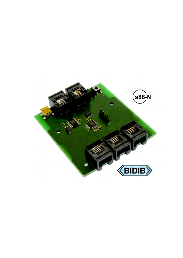
4. Your s88-BiDiB-Link
The s88-BiDiB-Link can be used as
a PC interface for the s88 bus and/or as
a BiDiB interface.
Fig.: BiDiB-Link
Page 7
Page 8

English s88-BiDiB-Link
Use as a PC interface for the s88 bus
The s88-BiDiB-Link has three RJ-45 sockets according to S88-N for the
connection of three s88 bus lines.
The standard s88-N regulates the assignment of commercial
Ethernet patch-cables for use in s88 feedback systems. Unlike
the 6-conductor connecting cables frequently used, the patch-cables
used in computer networks are screened against outside electric
signals. Thus using patch-cables reduces the liability to interference
considerably.
You can connect to each of the three RJ-45 sockets 512 earth contacts
or
32 x 16-fold feedback modules or
64 x 8-fold feedback modules,
which corresponds to 1536 feedback sections in total.
For the data transfer to the PC you can choose between:
HSI-88-mode. Hint: It is used the HSI-88 protocol for serial
interfaces, not the HSI-88-USB protocol.
BiDiB-protocol. The connected s88 modules are administered as
BiDiB knots by the interface.
Use as a BiDiB interface
You can connect a maximum of 32 BiDiB knots to one s88-BiDiB-Link
via two RJ-45 sockets. The assignment of the BiDiB knots to the two
RJ-45 sockets is optional.
Simulaneous use as a s88 and a BiDiB interface
It is possible to use the interface simultaneously as a s88 interface and
a BiDiB interface, there are no restrictions according to the number of
s88 modules or BiDiB knots to be connected. In this case data transfer
to the PC according to the BiDiB protocol is mandatory.
Page 8
Page 9

s88-BiDiB-Link English
5. Technical specifications
Supply voltage via the USB connection
Current consumption (without
connected devices)
max. 40 mA
Data protocols S88 (HSI-88)
BiDiB
Interfaces for s88 bus 3 RJ-45 sockets
according to S88-N
for 512 earth contacts each
Interfaces for BiDiBus 2 RJ-45 sockets
for max. 32 BiDiB knots
PC interface USB 2.0 (connector: Mini-B)
Protected to IP 00
Ambient temperature in use 0 ... +60 °C
Ambient temperature in storage -10 ... +80 °C
Comparative humidity allowed max. 85 %
Dimensions of the PCB
Dimensions including housing
approx. 72 x 82 mm
approx. 100 x 90 x 35 mm
Weight of the assembled board
Weight including housing
approx. 27 g
approx. 75 g
Page 9
Page 10

English s88-BiDiB-Link
6. Connecting the s88-BiDiB-Link
Connect the s88-BiDiB-Link via RJ-45 patch cables to the s88 modules
or the BiDiB knots. For the sake of clarity, we recommend to use
different coloured patch cables for different types of bus lines, e.g.
green for the BiDiBus,
blue for the s88 bus.
6.1. Use as a s88 interface
Connecting the s88 bus lines
You can connect a maximum of 512 earth contacts to each of the three
s88 connections, or worded differently:
32 x 16-fold feedback modules or
64 x 8- fold feedback modules.
When connecting s88 feedback modules not providing a RJ-45
connection according to S88-N but only a 6-pole plug connector, you
need an additional adapter S88-A. These are available in different
versions for various mounting situations.
Settings
In order to transfer feedback data from the inverface to the PC in HSI88 mode, you have to insert a short circuit jumper on JP3. As long as
the connection is open, data are transferred according to the BiDiB
protocol.
Please note: When using the s88-BiDiB-Link simultaneously as a s88
and a BiDiB interface, you have to choose the BiDiB protocol for the
data transfer (to keep the connection JP3 open).
Page 10
Page 11

s88-BiDiB-Link English
6.2. Use as a BiDiB interface
Connecting the BiDiB knots
You can connect a maximum of 32 BiDiB knots to the s88-BiDiB-Link.
The assignment to the two BiDiB connections is optional.
Setting the protocol
When using the s88-BiDiB-Link as a BiDiB interface, you have to choose
the BiDiB protocol for the data transfer from the interface to the PC. For
that purpose the connection JP3 has to be open.
Mounting the terminating jumpers
When the s88-BiDiB-Link is installed at one end of the BiDiBus-line (i.e.
with only one branching RJ 45 cable), you have to mount the
terminating jumpers JP1 and JP2. In state of delivery the terminating
jumpers JP1 and JP2 are not inserted.
Please note: When not mounting terminating jumpers with the BiDiBLink at one end of a bus line, interferences in data transfer due to
distortion of the electrical signals possibly occur.
When subsequently connecting one ore more additional devices to a
BiDiBus-line you have to dismount the terminating jumpers with the
s88-BiDiB-Link.
Please note: With a device with mounted terminating jumpers but not
installed at one end of bus line data transfer possibly collapses.
Faulty mounted or missing terminating jumpers cannot cause damages
at the s88-BiDiB-Link.
Page 11
Page 12

English s88-BiDiB-Link
6.3. Connecting the PC
Connect the s88-BiDiB-Link via the USB cable included in the package
to you PC. In case the USB interface has not been installed on your PC,
you will receive an appropriate indication. You have to download the
driver from the internet then.
Settings in the software for HSI mode
When transferring data from the interface to the PC in HSI-88-mode,
you have to make the following settings in your software:
data transfer according to the HSI-88-protocol for serial interfaces,
number of s88 modules connected to the three bus lines. Hint:
Observe the numbers of the bus lines (see figure in section 4).
Settings in the software for BiDiB
BiDiB has been designed that way connected BiDiB-knots log in
themselves at the software.
S88 modules are administered by the interface as BiDiB-knots when
data transfer to the PC is effected via the BiDiB-protocol.
Page 12
Page 13

s88-BiDiB-Link English
7. Updates
In order to adapt the s88-BiDiB-Link to new developments, you can
perform a software update via BiDiB. For that purpose start the suitable
PC software. As an alternative (e.g. when the software does not
provide an update function) you can perform the update with special
tools (e.g. BiDiB-Monitor or BiDiB-Wizard). Start the suitable part of the
program and follow the instructions.
For starting the update mode, you must keep the identify button
pushed while making contact to the PC (via the USB cable).
When not having integrated the s88-BiDiB-Link in a BiDiB-control, you
can send in the module for updating.
Page 13
Page 14

English s88-BiDiB-Link
8. Check list for troubleshooting
Data are not transferred properly.
Possible cause: The connection(s) between the s88-BiDiB-Link and the
feedback modules / the BiDiB knots are interrupted. Check the
connections.
Possible cause: The terminating jumper has not been inserted although
the s88-BiDiB-Link is installed at the end of a BiDiBus line or the
terminating jumper has been inserted although the s88-BiDiB-Link is
not installed at the end of a BiDiBus line Check the terminating
jumpers.
Hotline: If problems with your device occur, our hotline is pleased to
help you (mail address on the last page).
Repairs: You can send in a defective device for repair (address on the
last page). In case of guarantee the repair is free of charge for you.
With damages not covered by guarantee, the maximum fee for the
repair is 50 % of the sales price according to our valid price list. We
reserve the right to reject the repairing of a device when the repair is
impossible for technical or economic reasons.
Please do not send in devices for repair charged to us. In case of
warranty we will reimburse the forwarding expenses up to the flat rate
we charge according to our valid price list for the delivery of the
product. With repairs not covered by guarantee you have to bear the
expenses for sending back and forth.
Page 14
Page 15

s88-BiDiB-Link English
9. Guarantee bond
For this product we issue voluntarily a guarantee of 2 years from the
date of purchase by the first customer, but in maximum 3 years after
the end of series production. The first customer is the consumer first
purchasing the product from us, a dealer or another natural or juristic
person reselling or mounting the product on the basis of selfemployment. The guarantee exists supplementary to the legal warranty
of merchantability due to the consumer by the seller.
The warranty includes the free correction of faults which can be proved
to be due to material failure or factory flaw. With kits we guarantee
the completeness and quality of the components as well as the function
of the parts according to the parameters in not mounted state. We
guarantee the adherence to the technical specifications when the kit
has been assembled and the ready-built circuit connected according to
the manual and when start and mode of operation follow the
instructions.
We retain the right to repair, make improvements, to deliver spares or
to return the purchase price. Other claims are excluded. Claims for
secondary damages or product liability consist only according to legal
requirements.
Condition for this guarantee to be valid, is the adherence to the
manual. In addition, the guarantee claim is excluded in the following
cases:
if arbitrary changes in the circuit are made,
if repair attempts have failed with a ready-built module or device,
if damaged by other persons,
if damaged by faulty operation or by careless use or abuse.
Page 15
Page 16

English s88-BiDiB-Link
10. EU declaration of conformity
This product conforms with the EC-directives mentioned below
and is therefore CE certified.
2004/108/EG on electromagnetic. Underlying standards: EN 55014-1
and EN 61000-6-3. To guarantee the electromagnetic tolerance in
operation you must take the following precautions:
Connect the transformer only to an approved mains socket installed
by an authorised electrician.
Make no changes to the original parts and accurately follow the
instructions, connection diagrams and PCB layout included with this
manual.
Use only original spare parts for repairs.
2011/65/EG on the restriction of the use of certain hazardous
substances in electrical and electronic equipment (ROHS). Underlying
standard: EN 50581.
11. Declarations conforming to the WEEE directive
This product conforms with the EC-directive 2012/19/EG on
waste electrical and electronic equipment (WEEE).
Don´t dispose of this product in the house refuse, bring it to the next
recycling bay.
Page 16
Page 17

n
n
Information and tips:
n
n
http://www.tams-online.de
n
n
n
Warranty and service:
n
n
Tams Elektronik GmbH
n
Fuhrberger Straße 4
DE-30625 Hannover
fon: +49 (0)511 / 55 60 60
fax: +49 (0)511 / 55 61 61
e-mail: modellbahn@tams-online.de
n
n
n
n
 Loading...