

Page 1
n
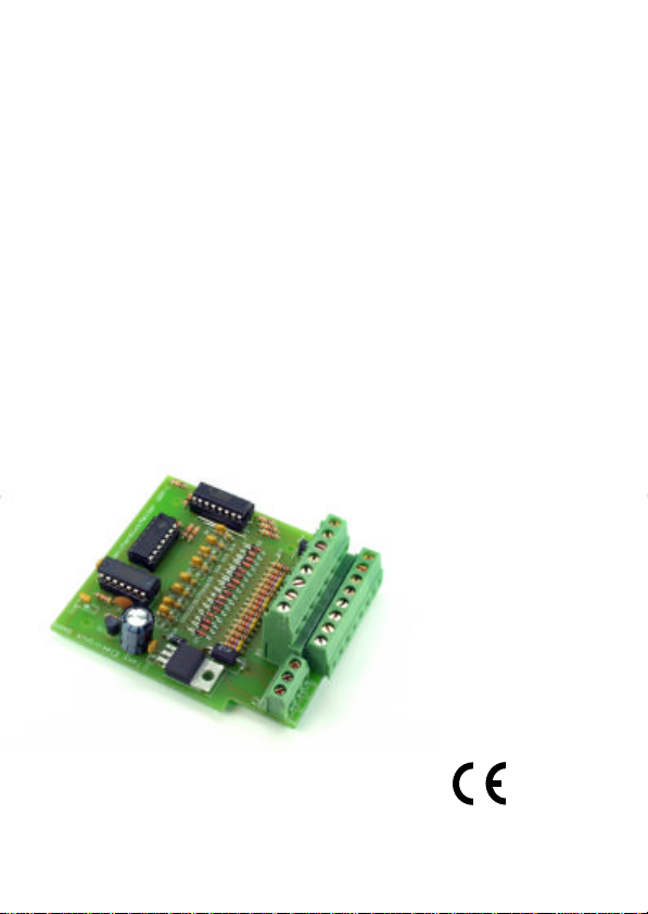
WRM-1
n
n
n
Weichenrückmelder
Points indicator
Indicateur de position
Wisselterugmelder
Art.-Nr. 21-01-027
Art.-Nr. 22-01-027
n
n
n
n
n
n Anleitung
n Manual
n Mode d´emploi
n Handleiding
n
n
n
Page 2

© 02/2005 Tams Elektronik GmbH
Alle Rechte, insbesondere das Recht der
Vervielfältigung und Verbreitung sowie der
Übersetzung vorbehalten. Vervielfältigungen
und Reproduktionen in jeglicher Form
bedürfen der schriftlichen Genehmigung
durch die Tams Elektronik GmbH.
Technische Änderungen vorbehalten.
n
n
n Deutsch 3
n English 19
© 02/2005 Tams Elektronik GmbH
All rights reserved. No part of this
publication may be reproduced or
transmitted in any form or by any means,
electronic or mechanical, including
photocopying, without prior permission in
writing from Tams Elektronik GmbH.
Subject to technical modification.
© 02/2005 Tams Elektronik GmbH
Tout droits réservés, en particulier les droits
de reproduction et de diffusion ainsi que le
traduction. Toute duplication ou
reproduction sous quelque forme que ce soit
nécessite l´accord écrit de la societé Tams
Elektronik GmbH.
Sous réserve de modifications techniques.
© 02/2005 Tams Elektronik GmbH
Alle rechten voorbehouden. Niets uit deze
publicatie mag worden vermenigvuldigd
opgeslagen of openbaar gemaakt, zonder
voorafgaande schriftelijke toestemming van
Tams Elektronik GmbH.
Technische wijzigingen voorbehouden.
n Français 33
n Nederlands 48
n
n
n
n
n
n
n
n
n
Page 3

English
Table of contents
How to use this manual 20
Intended use 20
Safety instructions 21
EMC declaration 23
Operation overview 23
Checking the package contents 23
Choosing a power supply 24
Technical specifications 24
Required tools and consumables 24
Safe and correct soldering 25
Assembling the kit 26
Performing a visual check 28
Functional test and
connecting the points indicator 29
Connecting a points decoder 30
FAQ 30
Manufacturer's note 31
Certification 31
Conditional warranty 31
Parts list I.1
Printed Circuit Board (PCB) layout (Fig.1) I.2
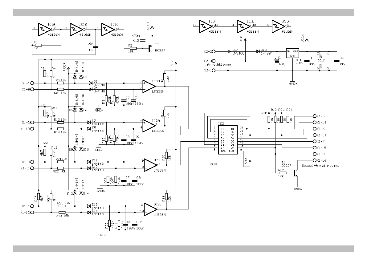
Circuit Diagram (Fig. 2) II
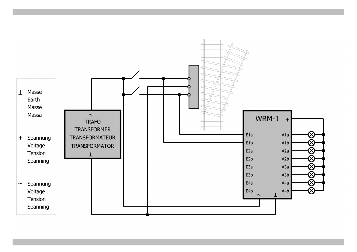
Connections 1 (Fig. 3a) III
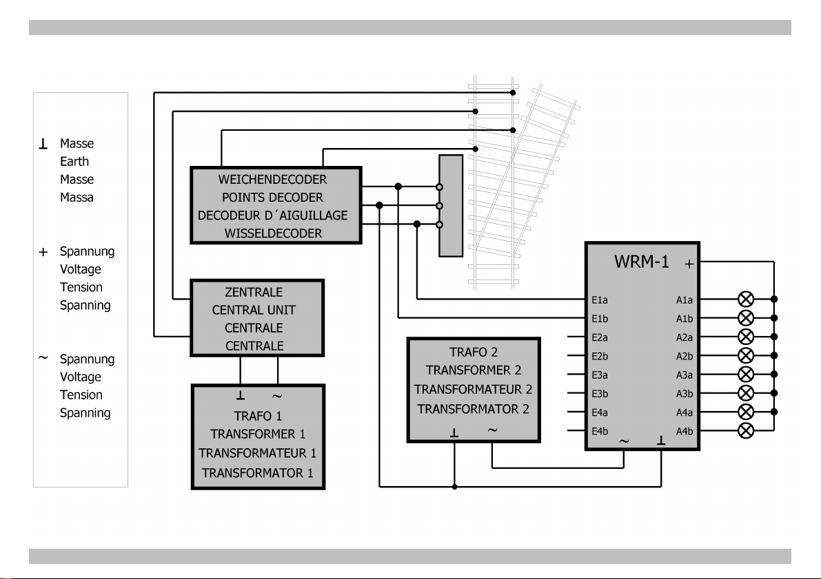
Connections 2 (Fig. 3b) - Connection of a points decoder IV
(Pages I to IV in the centre of this handbook are removeable)
Page 19
Page 4

English
!
How to use this manual
If you have no specialist technical training, this manual gives step-bystep instructions for safe and correct assembly of the kit or fitting of
ready-built modules, and operation. Before you start, we advise you to
read the whole manual, particularly the chapter on safety instructions
and the FAQ chapter. You will then know where to take care and how
to prevent mistakes which take a lot of effort to correct.
Keep this manual safely so that you can solve problems in the future. If
you pass the kit on to another person, please pass on the manual with
it.
Intended use
Caution:
Integrated circuits are very sensitive to static electricity. Do not touch
components without first discharging yourself. Touching a radiator or
other grounded metal part will discharge you.
The kit or the ready-built module can be assembled or fitted using this
manual. The ready-built module is designed for use in model railways.
It indicates the actual position of up to four solenoid accessories
(points, signals, etc.).
The kit and the ready-built module are not suitable for children under
the age of 14.
Reading, understanding and following the instructions in this manual
are mandatory for the user.
Any other use of the kit is inappropriate and invalidates any guarantees.
Page 20
Page 5

English
Safety instructions
Mechanical hazards
Cut wires can have sharp ends and can cause serious injuries. Watch
out for sharp edges when you pick up the PCB.
Visibly damaged parts can cause unpredictable danger. Do not use
damaged parts: recycle and replace them with new ones.
Electrical hazards
§ Do not touch powered, live components.
§ Do not touch conducting components which are live due to
malfunction.
§ Avoid short circuits.
§ Do not connect the circuit to a higher voltage than designed.
§ Impermissibly high humidity.
§ Condensation building up can cause serious injury due to electrical
shock.
Take the following precautions to prevent this danger:
§ Never perform wiring on a powered module.
§ Only use low power for this module as described in this manual and
only use certified transformers.
§ Connect transformers and soldering stations only in approved mains
sockets installed by an authorised electrician.
§ Observe cable diameter requirements.
§ Assembling the kit should only be done in closed, clean, dry rooms.
Beware of humidity.
§ If the humidity in the room is too high, please do not start working
until after a minimum of 2 hours of acclimatisation.
§ Use only original spare parts if you have to repair the kit or the
ready-built module.
Page 21
Page 6

English
Fire risk
Touching flammable material with a hot soldering iron can cause lifethreatening fire, burns and toxic smoke. Connect your soldering iron or
soldering station only when actually needed. Use the correct soldering
iron or station and never leave a hot soldering iron or station
unattended.
Thermal danger
A hot soldering iron or liquid solder accidentally touching your skin can
cause skin burns. As a precaution:
§ use a heat-resistant mat during soldering,
§ always put the hot soldering iron in the soldering iron stand,
§ point the soldering iron tip carefully when soldering, and
§ remove liquid solder with a thick wet rag or wet sponge.
Dangerous environments
A working area that is too small or cramped is unsuitable and can cause
accidents, fires and injury. Prevent this by working in a clean, dry room
with enough freedom of movement.
Other dangers
Children can cause any of the accidents mentioned above because they
are inattentive and not responsible enough. Children under the age of
14 should not be allowed to work with this kit or the ready-built
module.
Little children can swallow small components with sharp edges. Life
threatening! Do not allow components to reach small children.
In schools, training centres, clubs and workshops, assembly must be
supervised by qualified personnel.
In industrial institutions, health and safety regulations applying to
electronic work must be adhered to.
Page 22
Page 7

English
EMC declaration
This product is developed in accordance with the European standards
EN 55014 and EN 50082-1, tested corresponding to the EC - directive
89/336/EWG (EMVG of 09/11/1992, electromagnetic tolerance) and
meets legal requirements.
To guarantee the electromagnetic tolerance you must take the
following precautions:
§ Connect the transformer only to an approved mains socket installed
by an authorised electrician.
§ Make no changes to the original parts and accurately follow the
instructions, circuit diagram and PCB layout included with this
manual.
§ Use only original spare parts if you have to repair the kit or the
ready-built module.
Operation overview
The module indicates the actual position of points (e.g. Märklin* M,
Märklin* K 15° to 1996) and signals with solenoid drive. Every indicator
can indicate the position of up to four points or signals. As the position
of the armature coil is analyzed, the module also reacts if points are
shifted manually. The evaluation ensues to ground so a digital checkback-decoder (e.g. Märklin* S 88) can be connected directly. This
means old points can be integrated in a computer-assisted digital model
railway system.
Checking the package contents
Check the contents of the package for completeness:
§ 1 kit, containing the components listed in the parts list and 1 PCB or
§ 1 ready-built module
§ 1 manual.
Page 23
Page 8

English
Choosing a power supply
The module is designed for connection to a model railway power
source, i.e. 12-18 Volt direct (d.c.) or alternating (a.c.) voltage.
Technical specifications
Supply voltage 12-18 Volt a.c. or d.c. voltage
Current consumption
(without connected loads) ca. 15 mA
Max. current loading 250 mA
Protected to IP 00
Ambient temperature in use 0 - + 60° C
Ambient temperature in storage -10 - + 80° C
Comparative humidity allowed max. 85 %
Dimensions ca. 73 x 80 mm
Weight ca. 66 g
Required tools and consumables
Make sure you have the following tools, equipment and materials ready
for use:
§ a heat-resistant mat
§ a soldering iron stand with tip-cleaning sponge
§ a small side cutter and wire stripper
§ a pair of tweezers and long nose pliers (not necessary for the
ready-built module)
§ an electronic soldering iron (max. 30 Watt) with a fine tip
§ tin solder (0,5 mm. diameter)
§ wire (diameter: > 0,22 mm² for all connections)
§ two lamps for the functional test
Page 24
Page 9

!
Safe and correct soldering
Caution:
Incorrect soldering can cause fires (through excessive heat). Avoid this
danger by reading the chapter Safety instructions again and
following the directions given.
If you have had training in soldering you can skip this chapter.
§ When soldering electronic circuits never use soldering-water or
soldering grease. They contain acids that can corrode components
and copper tracks.
§ Only use tin solder SN 60 Pb (i.e. 60 % tin, 40 % lead) with rosin-
based flux.
§ Solder fast: long soldering can destroy components and copper
tracks, and damages through plated holes.
§ Use a small soldering iron with max. 30 Watt. Keep the soldering tip
clean so the heat of the soldering iron is applied to the solder point
effectively.
§ Observe correct polarity orientation of semi-conductors, LEDs
electrolytic capacitors and integrated circuits before soldering and
ensure that the solder time does not exceed 5 seconds, otherwise
components can be damaged.
§ Apply the soldering tip to the soldering spot in such a way that the
part and the soldering spot are heated at the same time.
Simultaneously add solder (not too much). As soon as the solder
becomes liquid take it away. Hold the soldering tip at the spot for a
few seconds so that the tin solder finds its way, then remove the
soldering iron.
§ Do not move the component for about 5 seconds after soldering. A
glossy and perfect soldering spot should remain.
§ To make a good soldering joint you must use a clean and
unoxidised soldering tip. Clean the soldering tip with a damp piece
of cloth, a damp sponge or a piece of silicon cloth.
English
Page 25
Page 10
English
§ Cut the wires after soldering directly above the PCB solder side with
a side cutter.
§ After placing the parts, please double check for correct polarity.
Check the PCB tracks for solder bridges, short circuits created by
accident. This would cause faulty operation or, in the worst case,
damage. You can remove excess solder by putting a clean soldering
tip on the spot. The solder will become liquid again and flow from
the soldering spot to the soldering tip.
Assembling the kit
You can skip this part if you have a ready-built module.
Preparation
Put the sorted components in front of you on your workbench. An
explanation of the separate electronic components follows:
Resistors
A resistor will "brake" the current. Mounting orientation is of
no importance. Because resistors are very small there is no
readable information on them, but their value is given with
colour rings.
Key:
Value Colour ring
4,7 kΩ yellow - violet - red (gold)
10 kΩ brown - black - orange (gold)
47 kΩ yellow - violet - orange (gold)
470 kΩ yellow - violet - yellow (gold)
The colour ring in brackets indicates the tolerance of the
resistor and is of no importance here.
Capacitors
There is a difference between “normal” capacitors and
electrolytic capacitors which have to be placed in a certain
direction. They have a very bright line at one end marked with
Page 26
Page 11
English
the minus (-) sign. That end must always be connected to
minus.
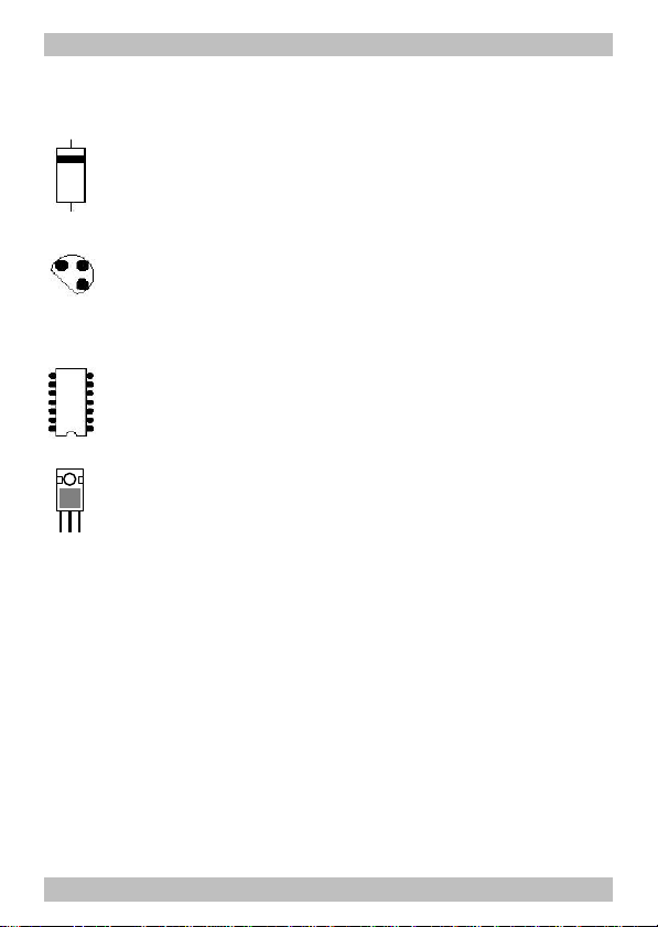
Diodes
Diodes allow current to flow in one direction only and have to
be placed in that direction. The characteristic for a diode is
the ring at one end. Place them as drawn in the PCB layout.
Transistors
Transistors are in fact power switches. They have three wires
and a flat part on the body. They also have to be placed in a
certain direction. The PCB layout will help you to place the
transistor. In the layout, the flat part of the transistor is shown.
ICs
The notch on the IC shows the mounting orientation. The PCB
layout shows this marking.
Voltage regulator
Voltage regulators are ICs in a transistor housing. They
transform a varying uncontrolled input voltage into a
unvarying output voltage.
Terminal strips
Terminal strips are solder-in screw-type terminals. They provide a
solder-free and safe connection of the cables to the circuit.
Assembling the kit
Start the assembly with the resistors. First solder the components on
the solder side of the PCB and then cut the excess wires with the side
cutter, as short as possible. Insert the wire bridges Br1 to Br7. Use the
off-cut wires of the resistors.
Continue the assembly with the diodes. Then insert and solder in the
IC-sockets for IC1 to IC3. The ICs must be mounted according to the
marking on the PCB.
Page 27
Page 12

English
!!!
Caution:
Do not touch the IC without first discharging yourself by touching a
radiator or other grounded metal parts. Do not bend the "legs" of the
IC.
Caution:
Electrolytic capacitors, transistors, ICs and diodes must be placed in the
right direction! If you solder them the wrong way the affected parts can
be damaged when you connect the power. In the worst case the whole
circuit can be damaged. In any case, a wrongly connected part will not
function.
Continue with the capacitors and the transistors. Then solder the
terminal strips X1 to X2. Before mounting, assemble the terminal strips.
Finally, insert IC1 to IC3 into the soldered IC-sockets.
Performing a visual check
Even if you have a ready-built module you must perform a visual check
that screws, plugs and other fasteners are firm and tight to exclude
transport damage.
Caution:
Do not power up the module yet.
Damaged material and/or incorrect handling of parts can always be a
danger. After assembling the kit, perform a visual inspection.
Check all nuts, pins and connections as well as the mechanical
connections for correct assembly.
Remove all loose parts, wire ends or drops of solder from the PCB.
Remove all sharp wire ends.
Check solder spots that are too close to each other for short circuits.
Check that all components are polarised correctly. When you have
taken all these precautions, go on to the next part.
Page 28
Page 13

English
!
!
Functional test and
connecting the points indicator
If you have purchased a ready-built module, check all functions.
Transport damage can never be excluded.
Check the function of the module with the points. Connect the four
functional sections of the points indicator with the points one after the
other. Proceed according to the diagram Connections 1 (fig. 3a) as
follows:
Caution:
Do not connect the module and the transformer to the power supply
yet.
There are terminal strips soldered to the in- and outputs. Insert the
connecting cables into the relevant terminals and fasten the screws.
Connect the test lamps to the outputs A1a and A1b and to the output
"+" of the module. Connect the points to the inputs E1a and E1b and to
ground. Finally connect the module to the transformer. Connect the
transformer to the mains.
One of the two lamps should now light. Switch or manually move the
connected points. The other lamp should now light and the first one
should go off.
Repeat the test with the other three functional sections of the points
indicator.
Caution:
If a component gets too hot, disconnect the points indicator and power
supply from the mains immediately. Possible short circuit! Check the
assembly!
After performing a successful functional test, disconnect the points
indicator from the power supply, the test-points and the lamps and
connect the module to the points or signals on your model railway.
Page 29
Page 14

English
!
!
Connecting a points decoder
If you want to switch the points via a points decoder, connect the
points indicator according to the diagram Connections 2 (fig. 3b). In
this case you need a second transformer which supplies only the points
decoder.
Caution:
You must not connect another circuit to this second transformer! A
digital points decoder must be connected via a relay! Possible short
circuit!
FAQ
§ Parts are getting too hot and/or start to smoke.
Disconnect the system from the mains immediately!
Possible cause: one or more components are soldered incorrectly.
à Perform a visual check.
§ The lamps connected to the module do not light.
Possible cause: The voltage supply is interrupted.
à Check the connection from the module to the transformer.
Possible cause: One or more lamps are defective.
à Check the lamps by connecting them directly to the voltage
supply.
Possible cause: The diode D17 is soldered in the wrong way.
à Reverse D17!
§ Both lamps light permanently.
Possible cause: The points have not switched properly and have
stopped midway.
à Check the position of the points.
Page 30
Page 15

English
§ There is no change over from the first to the second lamp after
switching the points.
Possible cause: The points are not properly connected to the points
indicator.
à Check the thre connections to the points.
§ A connected relay "rattles" (does not switch properly).
Possible cause: The module is connected to a.c. voltage.
à Solder a capacitor in parallel to the relay (> 100 µF).
If you cannot find the problem, please return the module for repair
(address on the cover page).
Manufacturer's note
According to DIN VDE 0869, the person who builds this kit or brings the
circuit into operation is the manufacturer of the product. If he sells the
product to another person he is responsible for passing on all the
relevant papers. Domestic appliances assembled from a kit are deemed
industrial products and must comply with health and safety regulations.
Certification
This product conforms with the EC- directive 89/336/EWG on
electromagnetic radiation and is therefore CE certified.
Conditional warranty
This product is guaranteed for two years. The warranty includes free
repair if the problem is due to material failure or incorrect assembly of
the ready-built module by us. Because we have no control over the
assembly of the kit, we can only guarantee the quality of the
components and the completeness of the kit.
Other claims are excluded. By law, we are not responsible for damages
or secondary damages in connection with this product. We retain the
Page 31
Page 16

English
right to repair, make improvements, supply spare parts or return the
purchase price.
The following invalidate the warranty:
§ using an unsuitable soldering iron, solder containing liquid acids or
similar,
§ if the kit is assembled and soldered poorly, or if damage is caused
by not following the instructions in this manual or the circuit
diagram,
§ if the circuit has been altered and repair attempts have failed,
§ if arbitrary changes in the circuit are made,
§ if parts are stored incorrectly and if the wires to the switches, the
power resistors, etc. are made incorrectly,
§ if parts other then the original ones delivered with this kit are used,
§ if the copper tracks or soldering points are damaged,
§ if parts are placed incorrectly or the circuit is connected incorrectly,
§ if damage occurs due to an overload of the circuit,
§ if the wrong power or current is connected,
§ if damaged by other persons,
§ if damaged by the wrong use or abuse of the circuit,
§ if parts are damaged due to static because they were touched
before a discharge is performed.
(*) Trade Marks: "Märklin" is a registered and protected trade mark of Gebr. Märklin & Co,
Stuttgarter Straße, Göppingen , Germany.
Page 32
Page 17

WRM-1
Stückliste - Parts list
Nomenclature - Stuklijst
Kondensatoren
Condensers
Condensateurs
Condensatoren
Dioden - Diodes
Diodes - Diodes
IC´s - ICs - CI´s - ICs
Spannungsregler - Voltage
regulator - Régulateur de tension
Spanningsregelaar
IC-Sockel - IC-socket
Soquet IC - IC-voetje 16-pol. 1 x
Widerstände
Resistors
Résistances
Weerstanden
Transistoren - Transitors
Doppel-Anreihklemme - Double
terminal strips - Borniers double-
Dubbele printkroonsteen
Anreihklemme - Terminal strip
Bornier - Printkroonstaan
C1 470 µF/ 25V
C2 10 nF
C3 - C11, C13 100 nF
C12 470 nF
D1 - D16 1N4148 *
D17 1N5400 *
D18 1N4002 *
IC1 40106
IC2 ULN 2004
IC3 LM339
IC4 7812
14-pol. 2 x
R1 47 kΩ
R2, R5, R6, R9, R10,
R13, R14, R17, R18,
R21, R22, R25, R26,
R29, R30, R33-R35
R3, R4, R11, R12,
R19, R20, R27, R28
R7, R8, R15, R16,
R23, R24, R31, R32
T1 BC337 *
T2 BC327 *
X1 8-pol.
X2 3-pol.
* oder ähnlich - or similar - ou équivalent - of gelijkwaardig
Seite - Page - Page - Pagina I.1
10 kΩ
4,7 kΩ
470 kΩ
Page 18
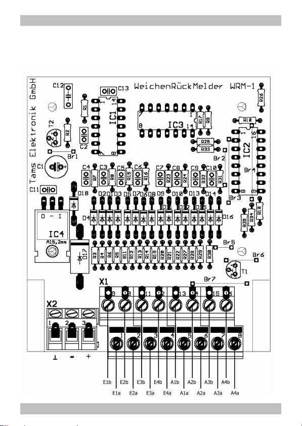
WRM-1
Bestückungsplan - PCB layout
Plan d´implantation - Printplan n n n Fig. 1
Seite - Page - Page - Pagina I.2
Page 19
WRM-1 WRM-1
Schaltplan
Circuit diagram
Schéma de principe
Schakelschema
n n n Fig. 2
Seite II Seite II
Page 20
WRM-1 WRM-1
Anschlußplan 1
Connections 1
Plan de raccordement 1
Aansluit plan 1
n n n Fig. 3a
Seite III Seite III
Page 21
WRM-1 WRM-1
Anschlußplan 2
Connections 2
Plan de raccordement 2
Aansluit plan 2
n n n Fig. 3b
Seite IV Seite IV
Page 22

n
n
n
Aktuelle Informationen und Tipps:
Information and tips:
Informations et conseils:
Actuele informatie en tips:
http://www.tams-online.de n
Garantie und Service:
Warranty and service:
Garantie et service:
Garantie en service:
Tams Elektronik GmbH
Rupsteinstraße 10
D-30625 Hannover
fon: 0049 (0)511 / 55 60 60
fax: 0049 (0)511 / 55 61 61
e-mail: [email protected]
n
n
n
n
n
n
n
n
n
n
n
n
 Loading...