

Page 1

TAMS 81622 PCI GPIO Card
for Linux
Installation & Operation Instructions
Page 2

TAMS 81622 PCI GPIO Card
Installation & Operation Instructions
Test & Measurement Systems Inc.
750 14th Street SW
Loveland, CO 80537
USA
Copyright Test & Measurement Systems Inc. 2000-2003
Page 3

Contents
General Information....................................................................... 3
Unpacking your product
Overview of the TAMS 81622 GPIO Interface
Installing the Interface ................................................................... 5
Driver Installation.......................................................................... 6
Interface Configuration.................................................................. 8
Related Software Documentation................................................ 11
Standard Instrument Control Library for Linux
BASIC For Linux
Additional GPIO Documentation Online
T echnical Information.................................................................. 12
Connector Pinouts
TAMS 81622 Enhancements beyond the HP 2074/5 .................. 14
TAMS 81622 PCI DMA
TAMS 81622 PCTL Delay
Booting After Configuration Changes
Appendix A: Wiring ................................................................... 17
Appendix B: File Locations........................................................ 20
Appendix C: TAMS 61622 SICL Extensions............................. 21
W arranty Information.................................................................... 28
Page 4

General Information
Unpacking Your Product
When you open your TAMS GPIO Card shipment, examine its contents.
Note: The name of the product you have purchased is the TAMS 81622
(GPIO Card for Linux). It includes the TAMS 622-66501 GPIO card and the
t61622 card driver for Red Hat Linux. See the ReadMe for the version supported.
Please complete the registration card and return it to TAMS.
3
Page 5

Overview of the TAMS 81622 GPIO Interface
This guide explains how to install and configure the TAMS 81622 GPIO (General
Purpose Input Output) interface.
GPIO is a parallel interface that is flexible and allows a variety of custom
connections. A PCI expansion slot is required to accommodate the GPIO
interface card.
The TAMS GPIO card has a rotary DIP switch on the upper edge to set the
unique identifier for the card. This is the only switch that needs to be set prior to
installing the card. All other configuration is done in software.
Since the configuration of the GPIO interface (aside from setting the unique card
identifier) is done in software, rather than using DIP-switches or jumpers, this
guide also provides an explanation of the configuration process as it relates to
SICL. A detailed description of the TAMS GPIO’s functionality is included to aid
in this configuration process.
The TAMS 81622 provides 16 bit data exchange with peripheral devices that do
not support more common interface protocols like HP-IB or RS-232. Connection
flexibility is augmented in the TAMS GPIO interface by extra status and control
lines, a choice of handshake methods, several data-latching options, and
selectable data width and polarity.
There are two basic modes for the data ports in the TAMS GPIO interface. The
TAMS GPIO can be configured like the HP 98622 GPIO interface, which is called
Compatibility Mode. Alternately, the TAMS 81622 can be configured with a bidirectional data port and auxiliary control lines, which is called Enhanced Mode
and is the same as that supported by HP 2074/5.
4
Page 6

Installing the Interface
This section explains how to install the TAMS GPIO interface in the computer. To
complete the installation:
1. Make sure the computer is shut down properly, the power is turned off, and
the power cord is unplugged.
2. Refer to the Owner’s Guide of your computer for instructions on opening
your computer and installing PCI boards.
3. The rotary DIP switch on the upper edge of the TAMS 622-66501 card
should be set to the PCI slot number the card is going to reside in. If you
have multiple TAMS 622-66501 cards installed in a single machine, it is
important that the rotary DIP switches each be set to a unique number,
which is guaranteed if you set the switch to the slot number. (Be sure to
note the position of the rotary DIP switch, as you will need to know this when
you configure the card.)
4. Install the GPIO interface in the PC by plugging the card into the PCI slot.
5. Follow the instructions being careful to handle the TAMS 622-66501 board
only by its metal bracket. Avoid contact with the edges. After the board has
been plugged in and the retaining screw installed the computer should be
reassembled.
6. Prepare and install the GPIO interface cable.
Note: The TAMS 622-66501 card is a PCI device. Unlike most EISA and ISA
devices a PCI device does not require an I/O address or IRQ setting. These
settings are handled automatically .
5
Page 7

Driver Installation
Note: Driver installation assumes basic knowledge about software installation
procedures specific to the platform. Refer to your platform specific operating
system documentation or contact your system administrator .
To install the t61622 driver it is not necessary for the T AMS 622-66501 interface
card(s) to be present in the system.
Note: You must have root permission to install the software. In addition, you
must have permission to write to the directories listed in Appendix B. Inst allation
of the TAMS GPIO driver (T81622) also requires that the TAMS I/O Libraries
(T82091) are already installed.
1 Make sure that the I/O Libraries (T82091) for Linux are installed.
2 Insert the installation CD-ROM into the drive and wait for the busy light to
remain off.
3 Mount the CD-ROM. For example:
/bin/mount /dev/cdrom /mnt/cdrom
On some systems this step will be unnecessary since the Linux system will
mount the CD-ROM automatically .
/dev/cdrom is the device file for your CD-ROM drive and /mnt/cdrom
is a directory used as a mount point.
4 Change to the directory where the driver is.
5 Use RPM to install the driver . Architecture-specific versions of the sof tware
have been provided for systems running the supported kernels; the
whichrpm.sh program returns the name of the correct RPM for your
system. (Note the use of backquotes (‘) rather than single quotes (‘).)
/bin/rpm –i ‘./whichrpm.sh‘
If this an upgrade over an existing version use the “-U” instead of “-i”:
/bin/rpm –U ‘./whichrpm.sh‘
6
Page 8

6 The T81622 RPM will automatically load the t61622 kernel module and build
the required device files.
7 Once the installation is complete, unmount the CD.
cd /
/bin/umount /dev/cdrom
8 Once the CD is unmounted, you may remove the media from the drive and
store it in a safe place.
In general, the installation procedure places the files in the necessary directories
by default. Appendix B is a reference for the Linux systems administrator, who
might wish to know where these files are placed.
You will still need to configure the new TAMS GPIO card as a SICL interface
card, as covered in the next section.
7
Page 9

Interface Configuration
After installation of the driver software and loading of the t61622 kernel module
(handled automatically by the RPM package), the SICL configuration file /etc/
opt/sicl/hwconfig.cf needs to be edited to reflect the new interface
card. The version of SICL you are using includes the /opt/sicl/bin/
iosetup program, this can be used in place of manually editing the
hwconfig.cf file. You will still want to refer to this section for a description of
the fields.)
After configuration, the system does NOT need to be rebooted, nor does the
driver module need to be reloaded. However , the SICL iclear function should be
used after making changes to ensure that the configuration changes have taken
effect. See the man page on iclear (1).
For further configuration information, see the “Installing and Configuring the I/O
Libraries” chapter of the I/O Libraries Installation and Configuration Guide for
Linux.
For each TAMS 622-66501 card that you want to configure in your system, you
need to add a line to the hwconfig.cf file. While most users do not need to
see or use this file directly , having used iosetup to make configuration changes,
the fields and their respective meanings are important to know to properly use
the GPIO card.
The content of each line is as follows:
<lu> <name> t61622 <location> <sig> <polarity> <mode> <read_clk> <delay>
The fields are defined as:
Logical Unit (lu) The SICL Logical Unit number for this interface. This number
must be unique for the SICL interfaces currently configured on this machine. A
good choice for a logical unit number would be 12.
Symbolic Name (name) The unique SICL symbolic name. A good choice would
be “gpio”.
Location The unique ID specified by the rotary DIP switch on the TAMS 62266501 being configured. This value is in the range 0-9
Signal (sig) Selects an Unix signal to be used by t61622 driver for interrupts. The value
must be in decimal format and must be 0 or one of the values defined in the signal.h
header file. Allowed signals are SIGIOT, SIGUSR1,
8
Page 10

SIGUSR2 SIGIO or SIGURG. A value of 0 sets the default signal which is
SIGURG. A signal is used by the t61622 driver to notify applications about kernel
events. You can select an alternate signal to avoid conflicts within your
application.
Polarity The logic polarity of various interface lines. A “0” sets active low
polarity; a “1” sets active high. Each bit controls the polarity of one function:
0b<Pullup><Data Out><Data In><PSTS><PFLG><PCTL>. For example,
0b11 1000 activates the pull up resistors and set s both Dat a Out and Dat a In to
active high, while PSTS, PFLG, and PCTL are all active low.
Mode A 2-digit hexidecimal number that onfigures handshake and data port
mode. The most significant digit configures the data port.
HP 98622 compatibility mode:
0 = No DOUT clear at reset
1 = Clear DOUT at reset
Enhanced (bi-directional DINs) data port:
2 = No DOUT clear at reset
3 = Clear DOUT at reset
The least significant digit selects the PFLG/PCTL handshake mode.
0 = Full handshake
1 = Pulse handshake
2 = Async-W rite/Pulse-Read handshake
For example, 0x10 specifies compatibility mode with DOUT cleared on reset and
full handshaking.
Read Clock (read_clk) Determines when data input registers are latched. The
first hex digit is for the upper (most significant) byte. Second hex digit is for the
lower byte. Valid values for each digit are:
0 = when register is read
1 = at busy edge
2 = at ready edge
Delay The delay (settling time) from data write to PCTL set:
0 = 200 nanoseconds
1 = 400 nanoseconds
2 = 700 nanoseconds
3 = 1.2 microseconds
4 = 2 microseconds
5 = 5 microseconds
6 = 10 microseconds
7 = 50 microseconds
9
Page 11

The t61622 driver provides an alternate delay configuration method. The delay
may be expressed in nanoseconds or in microseconds. If the delay is expressed
in nanoseconds the decimal value representing that delay should be suffixed with
“ns”. If the delay is expressed in microseconds the decimal value representing
delay should be suffixed with “us”. A decimal point is allowed. The minimum
delay is 90ns and maximum delay is 245us. Examples: 150ns, 2500ns (same as
2.5us), 1.15us, 90us.
10
Page 12

Related Software Documentation
St andard Instrument Control Library for Linux
To configure the TAMS GPIO interface for the Standard Instrument Control
Library (SICL) for Linux, see the “Installing and Configuring the I/O Libraries”
chapter of the I/O Libraries Installation and Configuration Guide for Linux.
To develop SICL I/O applications for the TAMS card on Linux, see the “Using
GPIO with SICL” chapter of the SICL User’s Guide. SICL functions, including
those that are GPIO specific, are fully defined in the SICL User’s Guide. The
T AMS card also provides functionality enhancement s.
BASIC for Linux
The TAMS GPIO interface is supported on version 11.0 of TAMS BASIC for
Linux.
When the GPIO interface has been configured for SICL, it is also ready to be
used from within BASIC for Linux. BASIC users will need to know the SICL
Logical Unit Number that has been assigned to the interface during
configuration, as this will correspond to the Select Code used to identify the
interface in their BASIC programs.
More information for the use of the GPIO interface is found on the TAMS BASIC
Documentation CD. Relevant sections are the “Linux Highlights” section of the
BASIC Language Reference, and the GPIO chapter of the BASIC Interface
Reference on the CD.
Additional GPIO Documentation Online
Technical articles and other additional GPIO documentation can be found on the
TAMS web site:
http://www.tamsinc.com/support/
11
Page 13

Technical Information
This section provides a detailed, functional description of the TAMS 81622 GPIO
interface. You will need to understand this information in order to set the
appropriate configuration values. This information should also be helpful when
you are preparing and installing the GPIO cable.
After you have read this section and decided how you want to configure the
TAMS 622-66501 card, refer to your software documentation to configure your I/
O application software for the TAMS 622-66501 card. (See the “Related Software
Documentation” section of this guide.)
This section contains the following :
• Connector Pinouts
• Data Lines
• Peripheral Information Lines:
♦ Peripheral Control and Peripheral Flag Handshake Lines (PCTL and
PFLG)
♦ Input/Output Direction Control Line (I/O)
♦ Peripheral S tatus Line (PSTS)
♦ Peripheral Reset Line (P_RESET)
♦ External Interrupt Request Line (EIR)
♦ Control Output Lines (CTL0 and CTL1)
♦ Status Input Lines (STI0 and STI1)
• Direct Memory Access (DMA)
12
Page 14
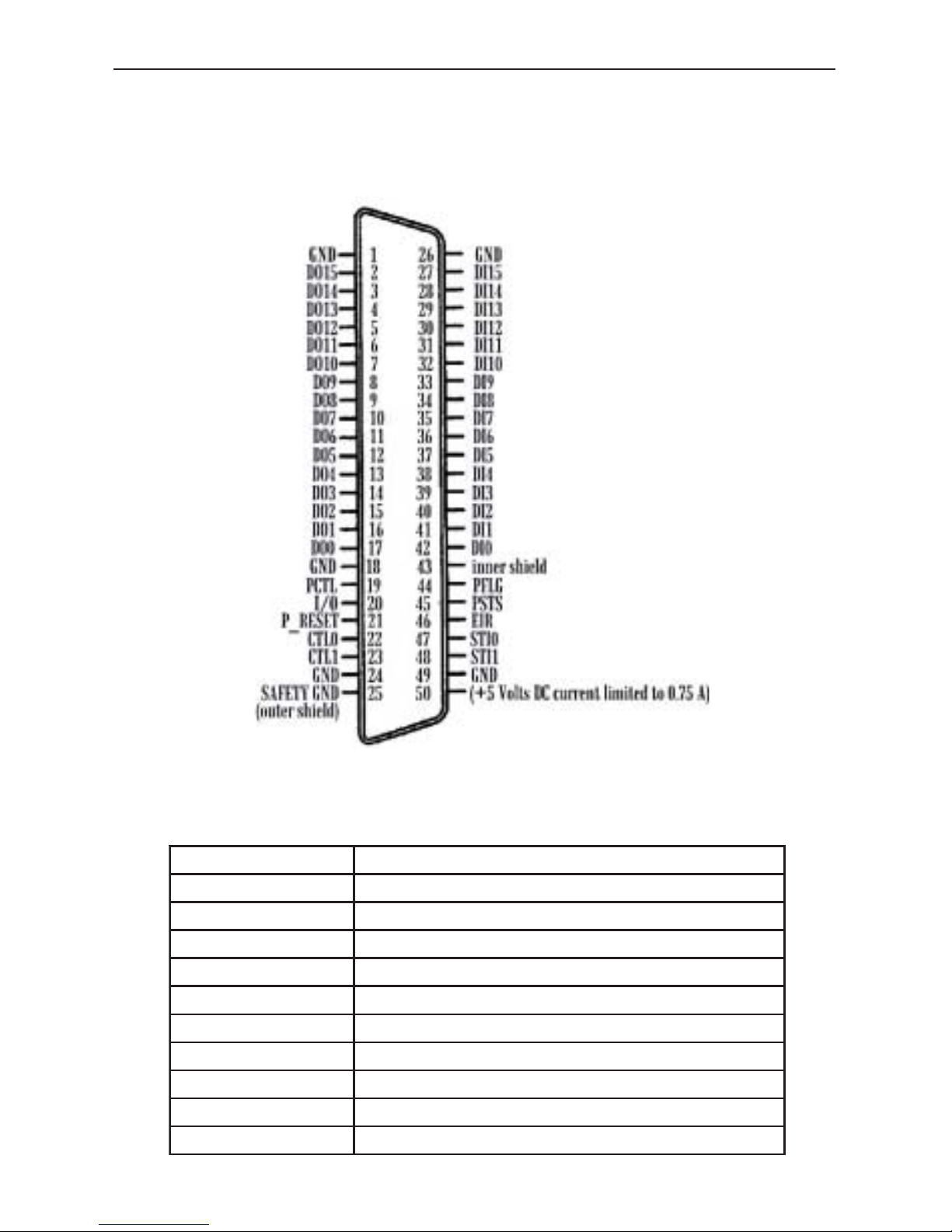
Connector Pinouts
The following figure shows you the Pinouts on the TAMS 622-66501 GPIO
interface connector .
TAMS 622-66501 GPIO Connector Pinouts
lebaL)s(eniL
51IDhguorht0IDtupnIataD
51ODhguorht0ODtuptuOataD
GLFPdnaLTCPekahsdnahgalFlarehpirePdnalortnoClarehpireP
O/IlortnocnoitceridtuptuO/tupnI
STSPsutatSlarehpireP
TESER_PteseRlarehpireP
RIEtseuqeRtpurretnIlanretxE
1LTCdna0LTCtuptuOlortnoC
1ITSdna0ITStupnIsutatS
05NIPA57.0otdetimiltnerrucCDstloV5+
13
Page 15

TAMS 81622 Enhancements beyond the HP 2074/5
TAMS 81622 PCI DMA.
The TAMS 81622 interface has two modes of transfer: DMA and interrupt driven.
A program may control transfer mode used by calls to ihint(). See the SICL
Reference Manual for more information.There are six values that could be
specified to this call:
• I_HINT_USEPOLL
• I_HINT_USEINTR
• I_HINT_USEDMA
• I_HINT_IO
• I_HINT_SYSTEM
• I_HINT_DONTCARE
If I_HINT_USEPOLL is specified, interrupt mode (I_HINT_USEINTR) is used.
This is due to the fact that with advances in hardware and operating systems,
there is no situation that using polled mode would have an advantage over
interrupt mode. Interrupt mode is not noticeably slower than polled and it
releases the processor while waiting for interrupts greatly improving system
overall performance.
If I_HINT_USEINTR is used, all inbound and outbound transfer will be performed
in interrupt mode. Each transfer of a single 8 or 16-bit data item (depending on
configured GPIO width) will be initiated, and the processor freed to perform other
tasks. Once the transfer is complete, the processor will initiate another transfer.
If the transfer is inbound and a termination and/or end character is specified, the
driver will check if the termination condition occurred before initiating another
transfer.
The igpioctrl(id, I_GPIO_READ_EOI,
<end_char>
) and
itermchr(id,
<term_chr>
) calls control end and termination characters.
If I_HINT_USEDMA is specified, DMA will always be used for outbound transfer.
For inbound transfer , if no termination nor end character is specified, DMA is
used. Otherwise interrupt mode (I_HINT_USEINTR) will be used. This will only
happen for the current transfer . No call to ihint() is required to restore DMA
transfer mode. For the next transfer , DMA will be resumed for outbound and if no
termination and/or end character is specified, for inbound transfers.
14
Page 16

If I_HINT_IO or I_HINT_SYSTEM or I_HINT_DONTCARE is specified, then
DMA (I_HINT_USEDMA) will be used. The I_HINT_IO is intended for best
transfer performance and I_HINT_SYSTEM for best system performance
executing other applications. The fact is that both qualities are delivered best
when DMA is used.
However , there is a difference between above three modes and
I_HINT_USEDMA. It is possible for PCI bus DMA transfers to fail due to
hardware or OS instabilities. If this happens, the three modes described in this
paragraph will switch from that moment to interrupt mode (I_HINT_USEINTR)
until the computer is rebooted. An explicit ihint() call with I_HINT_USEDMA will
always use DMA; and, if a DMA bus error occurs, the iread or iwrite will return
with an error . That said, the PCI bus DMA error is very unlikely to occur.
TAMS 81622 PCTL delay.
The TAMS 81622 is much more flexible than any other available GPIO interface.
With the HP 2074/5 interface a user has a choice of one of eight delay time
values. The gaps between those values are significant and prevent performance
optimization. The TAMS 81622 accepts values directly in nanoseconds. The
range extends from 90 nanoseconds to 245000 nanoseconds (245
microseconds) allowing optimal transfer performance according to the length of
cable used. In addition, the time specified is applied with accuracy at any mode
of transfer , while other available GPIO interfaces add as much as 500 ns when
different modes are used. This caused users to configure more PCTL time than
actually required in order to compensate for worst possible transfer mode cases.
The TAMS 81622 PCTL delay is configurable via the SICL iosetup utility or it may
be changed at any time from within an application by a call to igpioctrl(id,
I_GPIO_PCTL_DELAY,
<val>
) where
<val>
could be one of eight HP 2074/5
compatible values, or directly a value in nanoseconds between 90 and 245000
inclusive.
The eight (0-7) HP 2074/5 compatible values are interpreted as follows:
0 - 200ns, 1 - 400ns, 2 - 700ns, 3 - 1.2µs, 4 - 2µs, 5 - 5µs, 6 - 10µs, 7 - 50µs.
Booting A f ter Configuration Changes
When the TAMS GPIO card is reconfigured via either the SICL configuration
utility or by manually editing hwconfig.cf the system does not require rebooting,
nor does the driver module need to be reloaded, for the changes to
15
Page 17

take effect. Changes t ake ef fect when a session on a newly configured interface
is started for the first time within a process.
Care should be taken when a running application is using the TAMS GPIO
interface while it is reconfigured.
If, for example, a polarity setting is changed on an interface while an application
is using it, it may take effect in the middle of a transfer causing undesired effects.
However , no fat al effects such as a system crash or device hang will be caused.
It is safest to perform an iclear on the interface after modifying it s
configuration to guarantee that it is in a known state.
16
Page 18

Appendix A: Wiring
Data Lines
There are 32 data lines on the TAMS GPIO: 16 designated as data input, and 16
designated as data output. Color codes are provided for the TAMS 622-001
GPIO cable and the HP 5061-4209 GPIO cable.
Data Input Lines
The 16 data input lines are labeled DI0 through DI15. The following table list s the
connector pin numbers and cable wire color codes for the data input lines.
Data Input Lines
lebaL.oNniP100-2269024-1605
0ID24yerGnoetihWkcalB
1ID14eulBnonworBnworB
2ID04teloiVnoetihWdeR
3ID93eulBnoetihWegnarO
4ID83neerGnoetihWwolleY
5ID73wolleYnoetihWneerG
6ID63egnarOnoetihWeulB
7ID53kniPnoetihWteloiV
8ID43neerGnonworBdeR/nworB/etihW
9ID33wolleYnonworBegnarO/nworB/etihW
01ID23egnarOnonworBwolleY/nworB/etihW
11ID13kniPnonworBneerG/nworB/etihW
21ID03yerGnonaTegnarO/deR/etihW
31ID92teloiVnonaTwolleY/deR/etihW
41ID82eulBnonaTneerG/deR/etihW
51ID72neerGnonaTeulB/deR/etihW
17
Page 19

Data Output Lines
The 16 data output lines are labeled DO0 through DO15. The following table list s
the connector pin numbers and wire color codes for the data output lines.
Data Output Lines
lebaL.oNniP100-2269024-1605
0ID24yerGnoetihWkcalB
1ID14eulBnonworBnworB
2ID04teloiVnoetihWdeR
3ID93eulBnoetihWegnarO
4ID83neerGnoetihWwolleY
5ID73wolleYnoetihWneerG
6ID63egnarOnoetihWeulB
7ID53kniPnoetihWteloiV
8ID43neerGnonworBdeR/nworB/etihW
9ID33wolleYnonworBegnarO/nworB/etihW
01ID23egnarOnonworBwolleY/nworB/etihW
11ID13kniPnonworBneerG/nworB/etihW
21ID03yerGnonaTegnarO/deR/etihW
31ID92teloiVnonaTwolleY/deR/etihW
41ID82eulBnonaTneerG/deR/etihW
51ID72neerGnonaTeulB/deR/etihW
18
Page 20

Peripheral Information Lines
The following table lists the connector pin numbers and wire color codes for the
peripheral information lines.
Peripheral Information Lines
lebaL.oNniP100-2269024-1605
DRG1 naTnowolleY
DRG81nworBnoteloiV
LTCP91etihWnonaTyerG/etihW
O/I02nworBnoyerGnworB/kcalB/etihW
TESER_P12kniPnoegnarOdeR/kcalB/etihW
0LTC22naTnonworBteloiV/deR/etihW
1LTC32naTnokniPyerG/deR/etihW
DRG42etihWnonworB
DRGytefaS52naTnoegnarO
DRG62wolleYnonaT
DRGytefaS24teloiVnonworB
GLFP44naTnoetihWyerG
STSP54yerGnonworByerG/kcalB/etihW
RIE64egnarOnokniPyerG/nworB/etihW
0ITS74nworBnonaTeulB/nworB/etihW
1ITS84kniPnonaTteloiV/nworB/etihW
DRG94nworBnoetihW
)desuf(5+05egnarOnonaT
19
Page 21
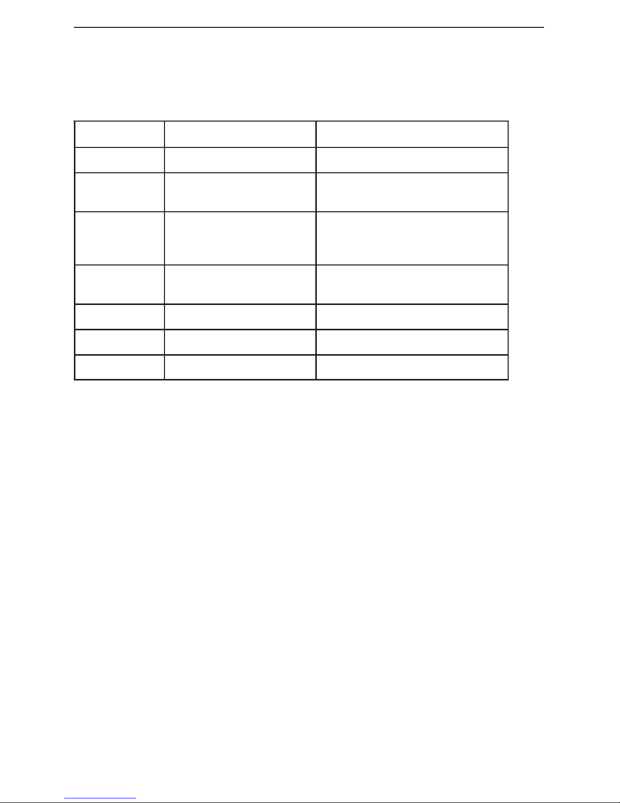
Appendix B: File Locations
The installation procedure places files in the following directories :
eliFnoitacoLnoitpircseD
os.22616tbil/lcis/tpo/yrarbilpiluTderahsLCIS
o.22616tlenrek</seludom/bil/
rahc/srevird/lenrek/>noisrev
eludomrevirdlenrek
22616td.tini/cte/ehtgnidaol)nu(roftpircstrats/pots
gnitaerc)nu(hetdnaeludomlenrek
selifecivedeht
22616t59S
22616t50K
d.]543[cr/cte/22616t/d.tini/cte/otknil
emdaer.22616t0.1-22618T/cod/erahs/rsu/elifemdaer
0.22616tved/0DIhtiwdracrofelifecivedlaiceps
n.22616tved/nDIhtiwdracrofelifecivedlaiceps
20
Page 22

Appendix C: TAMS 81622 SICL Extensions
All of the TAMS 81622 SICL extension functions are implemented by using the
header file t61622sicl.h and the standard SICL functions igpioctrl and igpiostat.
These two functions are described below:
IGPIOCTRL
Supported sessions: . . . . . . . . . . . . . . . . . . . . . . . . . interface
Affected by functions: . . . . . . . . . . . . . . . . . . . . . . . . ilock, itimeout
C Syntax
#include <sicl.h>
#include <t61622sicl.h>
int igpioctrl (id, request, setting);
INST id;
int request;
unsigned long setting;
IGPIOSTAT
Supported sessions: . . . . . . . . . . . . .. . . . . . . . . . . . . .interface
C Syntax
#include <sicl.h>
#include <t61622sicl.h>
int igpiostat (id, request, result);
INST id;
int request;
unsigned long *result;
21
Page 23
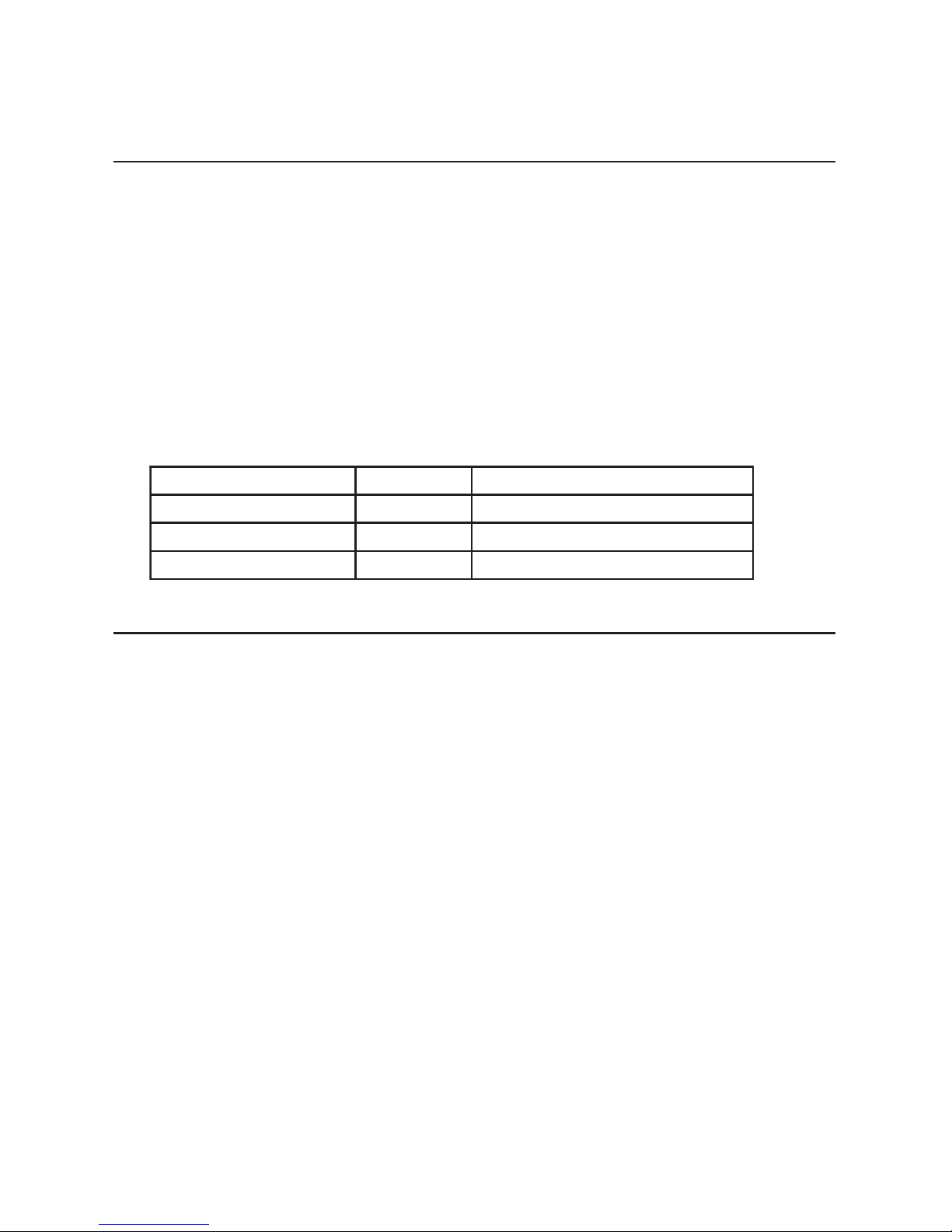
The following are all of the TAMS 81622 SICL extensions and some examples of
how to use them.
TAMS 81622 PCTL delay
The TAMS 81622 PCTL delay function provides an extended PCTL delay
control that was not available before. Besides the standard 0-7 values for delay
used with HP cards, the delay of the TAMS 81622 may be set directly in
nanoseconds.
Examples:
Setting the PCTL delay to 560ns
igpioctrl(id, I_GPIO_T61622_DL Y_TM, 560)
Reading the PCTL delay in nanoseconds
igpiostat(id, I_GPIO_T61622_DL Y_TM, &dtm)
Important time defines for the PCTL delay (in nanoseconds)
NIM_YLD_22616T09yaledLTCParofmuminiM
PTS_YLD_22616T06petsevitceffeerawdraH
TFD_YLD_22616T004toobnodedaoleulaV
XAM_YLD_22616T007542yaledLTCParofmumixaM
TAMS 81622 Filtering
This feature allows filtering of DIN[0..15], STI0, STI1 and EIR lines for glitch
rejection.
There are two different requests for this function:
I_GPIO_T61622_FLT_EN controls what groups are going to be enabled for
filtering. The groups are DIN[0..15], STI[0..1] and EIR. This destroys the old
setting and replaces it with the provided setting.
I_GPIO_T61622_FLT_TM sets the time in nanoseconds for the group or groups
that are enabled. The time set is common for all of the lines within those groups.
No individual lines can be controlled. The defines T61622_DIN, T61622_STI,
and T61622_EIR control DIN[0..15], STI[1..0] and EIR groups respectively.
Examples:
Using I_GPIO_T61622_FL T_EN
Enable DIN group for filtering
igpioctrl(id, I_GPIO_T61622_FL T_EN, T61622_DIN);
Read what groups are enabled for filtering
igpiostat(id, I_GPIO_T61622_FL T_EN, &fen);
22
Page 24
Using I_GPIO_T61622_FLT_TM
Set filtering to 1
µµ
µµ
µs (microsecond, 1000 nanoseconds)
igpioctrl(id, I_GPIO_T61622_FL T_TM, 1000)
Read the time set for filtering in nanoseconds
igpiostat(id, I_GPIO_T61622_FLT_TM, &ftm)
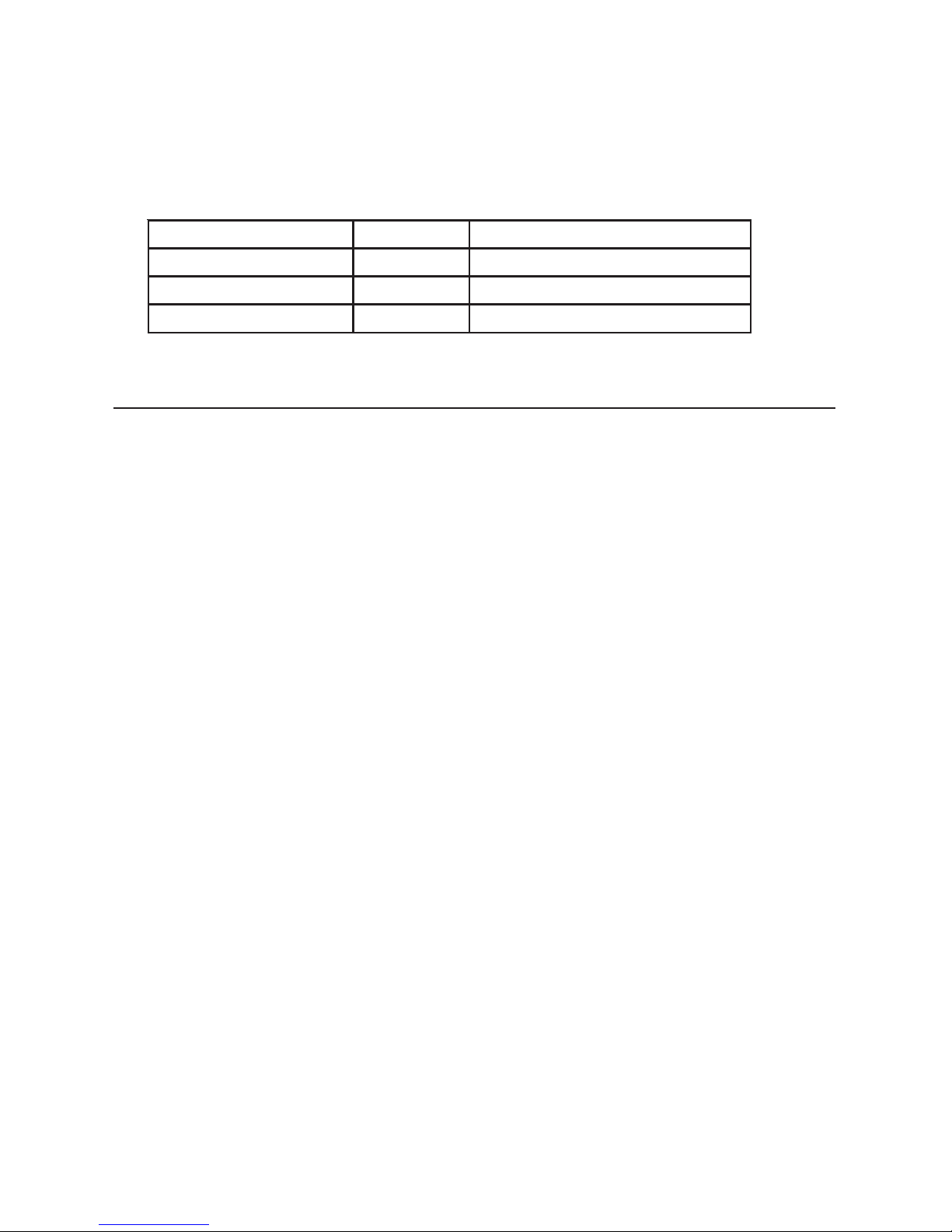
Important time defines for line filtering (in nanoseconds)
NIM_TLF_22616T03emitgniretlifmuminiM
PTS_TLF_22616T06petsevitceffeerawdraH
TFD_TLF_22616T051toobnodedaoleulaV
XAM_TLF_22616T00351emitgniretlifmumixaM
TAMS 81622 Polarity
This function allows for complex, individual polarity setting for DIN, STI0, STI1,
and EIR. The polarity of nineteen lines (DIN[0..15], STI[0..1] and EIR) can be
controlled independently . It enables interrupt control on either rising or falling
edge of a line level transition.
For the DIN lines, interpretation and implementation of the polarity is identical to
the standard GPIO DIN polarity as described in the SICL documentation.
For the STI and EIR lines, the standard GPIO interface does not provide polarity
configuration. This is a TAMS 81622 extension to the HP GPIO.
To maintain maximum compatibility with the standard GPIO, the following rules
apply:
• For STI and EIR lines, if their polarity is set to 0, their behavior is fully
compatible with standard GPIO. If set to 1, polarity is reversed for these
lines.
• For DIN lines, 81622 extensions allow the user to set the polarity for each
line independently . Setting the DIN polarity with standard GPIO SICL igpioctrl
(id, I_GPIO_POLARITY, setting) is still supported and will cause the
setting or clearing of all the DIN lines’ polarity with a single call. This is
because the standard allows only for all of the DIN lines’ polarity to be set at
a time. This guarantees backwards compatibility.
Examples:
Setting polarity for only DIN6 and EIR lines
igpioctrl(id, I_GPIO_T61622_POL, T61622_DIN06 | T61622_EIR)
Reading back the polarity setting
igpiostat(id, I_GPIO_T61622_POL, &pol);
23
Page 25

TAMS 81622 Latching
This function allows latching the levels of the lines to be enabled in the three
different groups (DIN[0..15], STI0, STI1, and EIR lines). The time at which the
latching occurs depends upon the polarity of the line being latched.
• If the polarity is set to 0, the latch will occur on a LO to HI logical transition.
• If the polarity is set to 1, the latch will occur on a HI to LO logical transition.
This function has three different request codes:
• I_GPIO_T61622_LAT_EN controls which group of lines are enabled for
latching, DIN[0..15], STI0, STI1 and/or EIR.
• I_GPIO_T61622_LAT_RD lets you read the latched lines.
• I_GPIO_T61622_LAT_CL clears the latched lines.
Examples:
Enable T61622_DIN06 and T61622_EIR
igpioctrl (id, I_GPIO_T61622_LA T_EN, T61622_DIN06 |
T61622_EIR)
Read what lines are enabled for latching
igpiostat(id, I_GPIO_T61622_LA T_EN, &len)
Read back what lines are latched
igpiostat(id, I_GPIO_T61622_LA T_RD, &lat)
Clear latched lines
igpioctrl(id, I_GPIO_T61622_LA T_CL, lat)
TAMS 81622 line interrupt
This function controls which lines can cause an interrupt. Interrupts on level
transitions on DIN[0..15], STI[0..1] and EIR lines can be controlled individually .
When the interrupt occurs depends upon the polarity:
• If the polarity is set to 0, the interrupt occurs on logical LO to HI transitions
• If the polarity is set to 1, the interrupt occurs on logical HI to LO transitions.
24
Page 26

If this function is combined with the TAMS 81622 latching function, then the
interrupt will fire only once. If this is the case, the latched lines need to be
cleared before other interrupts can happen from those lines.
If one or more interrupts occur, the interrupt handler is called with the “reason”
parameter equal to I_INTR_GPIO_T61622 and the “sec” parameter is the mask
of the lines that caused the interrupt.
The mask is always a subset of the following:
T61622_DIN | T61622_STI | T61622_EIR | T61622_RDY
Examples:
Enabling DIN4 line to interrupt
igpioctrl(id, I_GPIO_T61622_INT_EN, T61622_INT_DIN04)
Checking what lines can interrupt
igpiostat(id, I_GPIO_T61622_INT_EN, &int)
TAMS 81622 Pull-up Resistors
I_GPIO_T61622_PUL controls if DOUT[0..15], CTL[0..1], PCTL, I/O, and
PRESET lines are pulled up with 4.7k resistors to +5V. There is no control for
individual lines. All lines are controlled at the same time.
Examples:
Turn all pull-ups ON
igpioctrl(id, I_GPIO_T61622_PUL, 1)
Check if pull-ups are on
igpiostat(id, I_GPIO_T61622_PUL, &pull)
Turn pull-ups OFF
igpioctrl(id, I_GPIO_T61622_PUL, 0)
TAMS 81622 Board ID
The 81622 is equipped with a rotary DIP switch. Its purpose is the identification
of each GPIO board on a system with multiple GPIO cards.
The user must set the switch position to a unique value for each card on the
system and then can read its value by using the request I_GPIO_T61622_CID to
check which physical card is associated with a specific opened session.
Examples:
Get the switch value
igpiostat(id, I_GPIO_T61622_CID, &swID)
25
Page 27
TAMS 81622 Handshake
The TAMS 81622 internal handshaking loop allows the testing/debugging of
GPIO applications without requiring anything to be connected to the TAMS 62266501 GPIO card.
This test mode only has an effect on handshaking transfers. If this mode is
enabled, the PCTL/PFLG are set in a loop mode and, as a consequence, no
external device is needed for the handshaking, because it is being generated
internally by the TAMS 622-66501 card.
The user can turn the mode on or off by using the request I_GPIO_TEST_ONLY.
If an invalid value is passed in it is ignored. The actual polarity of PCTL and
PFLG lines does not affect the internal handshaking loop mode.
Examples:
Enable loop test mode
igpioctrl(id, I_GPIO_TEST_ONL Y, T61622_HSHK_LOOP)
Get test settings
igpiostat(id, I_GPIO_TEST_ONL Y, &test)
Disable loop test mode
igpioctrl(id, I_GPIO_TEST_ONL Y, 0)
Important time defines for loop test mode
POOL_KHSH_22616T10000000x0LTCPdnaGLFPpool
ENON_YLD_22616T20000000x0yaledonhtiwpool
ENON_KHSH_22616T40000000x0gnikahsdnahonhtiwpool
TAMS 61622 DOUT read
The I_GPIO_T61622_DOUT reads the value of the DOUT lines. The value read
is not affected by the DOUT polarity.
Example:
Get the DOUT value
igpiostat(id, I_GPIO_T61622_DOUT, &dout)
TAMS 61622 Macros
The following is a table with all of the macro definitions passed to the TAMS
61622 SICL extension functions. Individual bits may be p assed to select specific
line(s).
26
Page 28

TAMS 61622 SICL extension function defines
T61622_DIN 0x0000FFFF DIN[0..15] 16 bit s
T61622_DIN_L 0x000000FF DIN[0..7] 8 bits
T61622_DIN_U 0x0000FF00 DIN[8..15] 8 bits
T61622_STI 0x00030000 STI[0..1] 2 bits
T61622_EIR 0x00040000 EIR 1 bit
T61622_RDY 0x00080000 RDY 1 bit
T61622_MORE 0x00100000 used inside driver only
T61622_ALL 0x000FFFFF all of above 20 bits
Individual bits for DIN and STI
T61622_DIN00 0x00000001
T61622_DIN01 0x00000002
T61622_DIN02 0x00000004
T61622_DIN03 0x00000008
T61622_DIN04 0x00000010
T61622_DIN05 0x00000020
T61622_DIN06 0x00000040
T61622_DIN07 0x00000080
T61622_DIN08 0x00000100
T61622_DIN09 0x00000200
T61622_DIN10 0x00000400
T61622_DIN11 0x00000800
T61622_DIN12 0x00001000
T61622_DIN13 0x00002000
T61622_DIN14 0x00004000
T61622_DIN15 0x00008000
T61622_STI0 0x00010000
T61622_STI1 0x00020000
27
Page 29

Warranty Information
ONE YEAR LIMITED WARRANTY
Test & Measurement Systems, Inc. warrants to the purchaser that the Interface card will be free of
all defects in material and/or workmanship for one year from the date of shipment to the
customer.
In the event of malfunction or failure attributable directly to faulty material and/or workmanship,
TAMS will at it’s option, repair or replace the defective product or components, to whatever
extent it shall deem necessary to restore the product or component, to proper operating condition.
TAMS may at its option repair or replace, a defective unit with a new or refurbished unit.
The customer shall be solely responsible for the failure of any TAMS product, resulting from
accident abuse, or misapplication of the product, and TAMS assumes no liability as a
consequence of such events under the terms of this warranty.
While TAMS has made every effort to provide clear and accurate technical information about the
application of this product, TAMS assumes no liability for any events arising out of the use of
this technical information.
This Warranty gives you specific legal rights and you may also have other rights which vary from
state to state, and from country to country.
This Warranty is in Lieu of all other express warranties which now or hereafter might otherwise
arise with respect to this product. ANY AND ALL IMPLIED WARRANTIES OF MERCHANT
ABILITY AND FITNESS FOR PARTICULAR USE, SHALL HAVE NO GREATER
DURATION THAN THE PERIOD FOR THE EXPRESS WRITTEN W ARRANTY
APPLICABLE TO THIS PRODUCT AS SHOWN ABOVE, AND SHALL TERMINATE
AUTOMATICALLY AT THE EXPIRATION OF SUCH PERIOD.
(Some states and countries do not allow limitations on how long an implied warranty lasts, so this
limitation may not apply to you) No action shall be brought for breach of any implied or express
warranty after one year subsequent to the expiration of the period of the express written warranty.
Incidental and consequential damages caused by malfunction, defect, or otherwise and with
respect to breach of any express or implied warranty, are not the responsibility of TAMS, and to
the extent permitted by law, are hereby excluded both for property and to the extent not
unconscionable, for personal injury damage. (Some states do not allow the exclusion or limitation
of incidental or consequential damages, so the above limitation or exclusion may not apply to
you.)
28
Page 30

TAMS 81622 GP-IO Card for Red Hat Linux
Printed in USA E011.01.03
Part #81622-90004
 Loading...