

Tamron AF 18-200MM F 3.5-6.3 XR DIII LD ASPHERICAL MACRO, SP AF 11-18MM F 4.5-5.6 DIII LD ASPHERICAL, SP AF 17-50MM F 2.8 XR DIII LD ASPHERICAL, AF 55-200MM F 4-5.6 DIII LD MACRO DATASHEET
side. A
200
135
10070503518
LO CK
200
135
10070503518
LO CK
200
135
10070503518
LO CK
200
135
10070503518
LO CK
m
f
t
1
0
0
3
0
7
3
2
8
5
3
1
.
4
8
0
.
4
5
1
2
0
50
1
0
0
7
0
1
3
5
3
5
18
200
2
1
m
f
t
1
0
0
3
0
7
3
2
8
5
3
1
.
4
8
0
.
4
5
1
2
0
50
1
0
0
7
0
1
3
5
3
5
18
200
3
m
f
t
1
0
0
3
0
7
3
2
8
5
3
1
.
4
8
0
.
4
5
1
2
0
50
1
0
0
7
0
1
3
5
3
5
18
200
2
1
55
8
5
7
0
1
0
0
1
3
5
0
55
8
5
7
0
1
0
0
1
3
5
0
2
1
55
8
5
7
0
1
0
0
1
3
5
0
2
1
200
1
0
0
8
5
70
135
200
8
5
70
1
0
0
135
1
200
8
5
70
1
0
0
135
2
1
15
13
13
14
15
15
13
200
135
10070503518
LOC K
12
13
11 15
200
135
10070503518
LOC K
13 11
12
15
200
135
10070503518
LOC K
131411
12
15
200
135
10070503518
LOC K
13
11 15
12
135
1008570
55
11
13
15
135
1008570
55
11
13
14
15
135
1008570
55
13
11 15
TLM-EFDSINPC-A13A14A15A16-U-0603
ENGLISH
FRANÇAIS
SP AF11-18mm F/4.5-5.6 DiII LD Aspherical [IF]
SP AF17-50mm F/2.8 XR DiII LD Aspherical [IF]
(
Model A13
(
Model A16
AF18-200mm F/3.5-6.3 XR DiII LD Aspherical [IF] Macro(Model A14
AF55-200mm F/4-5.6 DiII LD Macro
1
2
3
A13
A13
A15
Focusing Zooming
35
.
0
1
4
.
0
1.25
5
5
.
0
1.
7
.
2
0
1
3
3
0
1
m
ft
5
5
0
7
5
11 15
8
0
0
1
5
3
1
0
0
2
1
5
3
0.
5
2
.
1
0.4
.5
5
1
.
0
2
7
.
0
3
1
0
3
1
ft
m
4 5 6
15
13
10
9
6
11
7
8
5
4
3
2
1
13
A13
10
9
8
17
A14
4
A16
1
16
A15
A14, A16
A14, A16
Nikon Canon
8
.4
1
0.45
3
1
5
2
8
3
7
20
0
00
3
1
ft
m
0
0
2
Focusing Zooming
(
Model A15
5
.4
0
1.48
1
3
5
2
3
8
7
20
0
30
10
t
m
f
8
1
5
3
0
5
70
0
0
1
5
3
1
A15
)
)
)
)
8
1
35
0
5
0
7
0
0
1
135
0
0
2
Konica Minolta
Focusing Zooming
13
12
11
10
9
8
7
6
5
4
3
2
1
Pentax
5
3
1
0
0
2
A14 Only
55
0
7
5
8
0
0
1
Thank you for purchasing the Tamron lens as the latest addition to your photographic
equipment. Di II lens (Digitally Integrated) series are designed for digital SLR cameras
with image sensors equivalent to APS-C size. Before using your new lens, please read
the contents of this Owner’s Manual thoroughly to familiarize yourself with your lens
and the proper techniques for creating the highest quality images possible.With proper
handling and care, your Tamron lens will give you many years of photographing
beautiful and exciting pictures.
Explains precautions that help to prevent problems.
Explains things you should know in addition to basic operations.
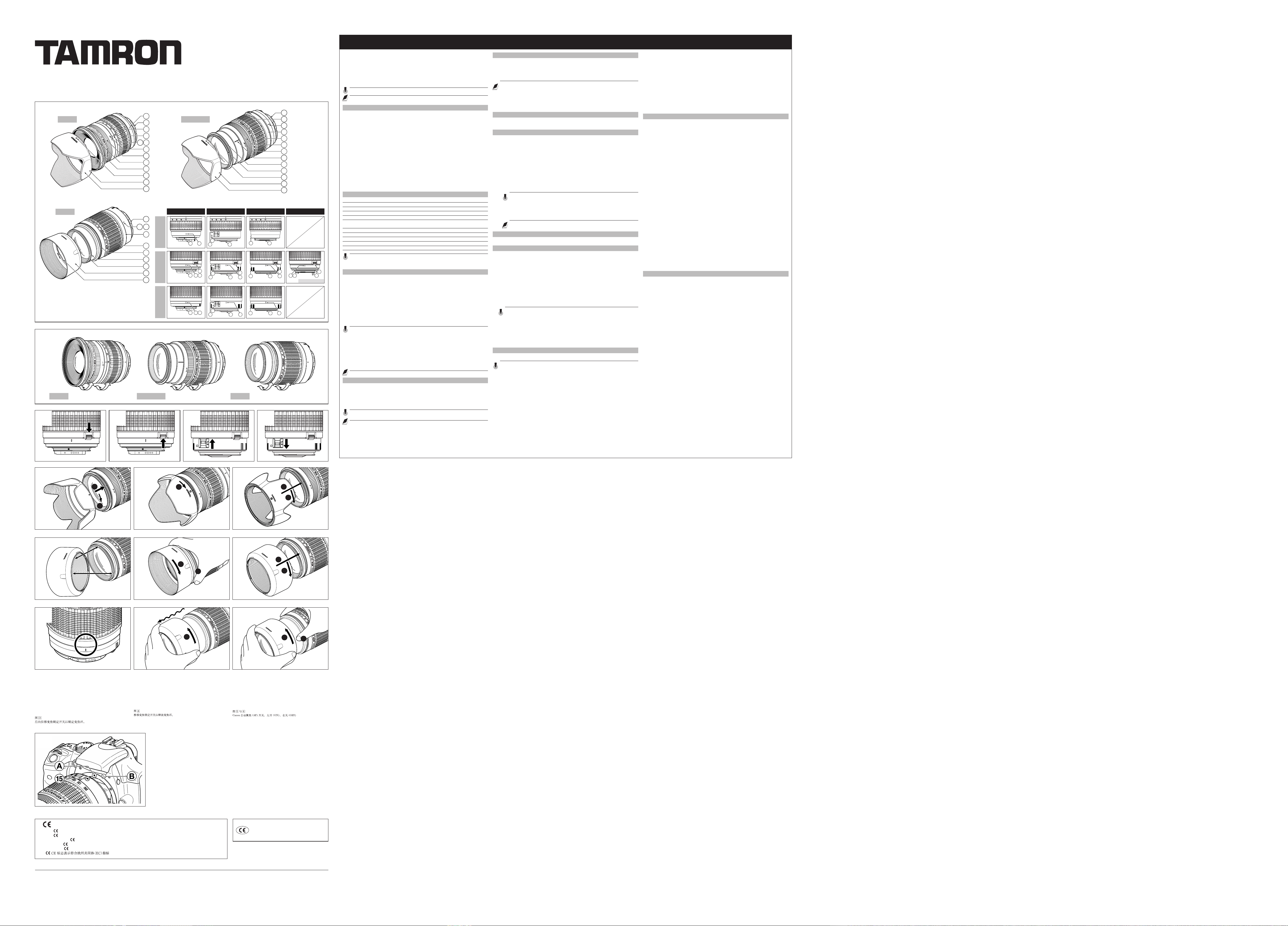
NOMENCLATURE (Refer to Fig. 1, if not specified)
1 Lens hood
2 Hood attaching alignment mark
3 Hood attaching indicator
4 Filter ring
5 Hood attaching bayonet ring
6 Distance index
7 Distance scale
8 Focusing ring
9 Zooming ring
0 Focal length scale
- Zoom index mark
= Zoom lock switch (A14 & A16: Figs. 3 & 4 )
q Lens mount/Lens mount contacts (Nikon)
w AF-MF altering switch (Canon Fig. 5 & 6 )
e Lens attachment mark
r Bayonet tab on the hood
t Bayonet tab on the lens
SPECIFICATIONS
A13 A14 A15 A16
Focal Length 11-18 mm 18-200 m m 55-200 m m 17-50 m m
Maximum A perture
Angle of View 103 °29' - 75°33' 75°33' - 7°59' 28°28' - 7°59' 78°45' - 31°11'
Lens Con struction
Minimum Foc using 0.25 m
Distance
Filter Size ø 77 mm 62 mm 52 mm 67 mm
Length 78.6 mm 83.7 mm 83.0 mm 83.2 mm
Diameter ø 83.2 mm 73.8 mm 71.6 mm 73.8 mm
Weight 345 g 398 g 295 g 430 g
Lens Hood DA13 DA06 DA15 DA09
F/4.5-5.6 F/3.5-6. 3 F/4-5.6 F/2.8
12/15 1 3/15 9/13 13/16
(through out the
entire zo om range)
0.45 m
0.95 m
(through out the 0.27 m
entire zo om range) entire zo om range)
(through out the
Lengths and weights listed in lens specifications are for lenses with Nikon mounts.
Features and cosmetic designs of lenses listed in this owner’s manual may be revised
without notice.
ATTACHING AND REMOVING THE LENS (A13, A14, A15, A16)
How to mount the lens
Removing the rear cap of the lens. Align the Lens attachment mark e on the lens
barrel with its counterpart on the camera mount and insert the lens.
Rotate the lens clockwise until it click-locks. For Nikon and Pentax models, align the
lens attachment mark on the camera and the Lens attachment mark e on the lens
to attach the lens. For Nikon models, align the lens attachment mark with the dot on
the camera and rotate the lens counter-clockwise until it click-locks.
How to detach the lens
Pressing the lens release button on the camera down, turn the lens counter-clockwise
(in case of Nikon lens, clockwise), and lift the lens off the camera’s lens mount.
The image circles of Di II lenses are designed to match the digital SLR cameras using
the image sensors equivalent to APS-C (approx. 15.523.2mm) . Do not use Di II lenses
with cameras using image sensors larger than APS-C. Using Di II lenses with such
cameras may cause vignetting on the image.
Some Canon digital SLR cameras have index marks for attaching both EF lenses (red)
A and EF-S lenses (white) B on the bayonet mount.
To attach Tamron DiII lenses, align the lens attachment mark on the lens e with the
index mark for EF lenses (red) A. Do not forcibly align the indicator on the lens e
with the index mark for EF-S lens (white) B.
Doing so could result in damage to the lens and/or camera.
For further details, please read the instruction manual of your camera.
FOCUSING (Autofocus) (Ref. Figs. 1 & 2 ) (A13, A14, A15, A16)
Switch the focusing mode switch of the camera to Auto focusing mode (AF) in case of
Nikon, Konica Minolta or Pentax. In case of a Canon camera, switch the AF/MF switch w
on the lens to AF. (Fig. 5). Press the shutter button lightly while viewing through the
camera’s viewfinder, the lens focuses automatically. An in-focus mark will light when
lens focuses on the main subject sharply. Press the shutter button further to photograph.
When set on AF mode, interfering with focusing ring 8 may cause serious damage to
the lens mechanism.
For further details, please read the instruction manual of your camera.
FOCUSING (Manual Focus) (Ref. Figs. 2 ) (A13, A14, A15, A16)
Switch the focusing mode switch of the camera to manual focusing mode (MF) in case
of Nikon, Konica Minolta or Pentax. In case of a Canon camera, switch the AF/MF switch
w on the lens to MF. (Fig. 6) Focus manually rotating the focusing ring while viewing
through the camera’s viewfinder. The main subject in the viewfinder will be sharp when
the lens is focused correctly.
Even in the MF mode, turning focusing ring 8 while pressing the shutter button halfway the
focus aid function lamp lights up when the picture is in focus.
At infinity, make sure the image in the viewfinder appears sharp. The infinity position on A13,
A14 & A16 is made with certain allowances to insure proper focus under a variety of conditions.
The focusing ring 8 of the A15 does not have a distance scale.
For further details, please read the instruction manual of your camera.
ZOOMING (Ref. Fig. 2 ) (A13, A14, A15, A16)
Rotate zooming ring 9 of the lens while viewing through the camera’s viewfinder and
compose your image at the chosen focal length.
ZOOM LOCK SWITCH (Ref. Figs. 3 & 4) (A14, A16)
Model A14 & A16 is equipped with zoom lock switch mechanism which prevent lens
barrel from extendting towards long focal length, while hanging around the neck.
Activate the switch at the shortest setting to stop the lens barrels from rotating and
extending.
How to activate the zoom lock switch mechanism
1) Locking: Set the zoom ring on the lens to the shortest position. Move the zoom
lock switch = toward the camera for locking the zooming ring 9. The lens
barrel is locked in position when the portion beneath “Lock” is shown in red and
the lens barrel does not rotate or extend by its own weight.
2) Releasing: Push the zoom lock switch = up. The zooming ring 9 is now
released and can be rotated.
Zoom lock switch can not be activated unless the lens is set to the shortest
position. Do not force the lock switch or try to rotate the zooming ring while
locked, doing so may damage the lens.
The zoom lock mechanism is made to prevent the lens barrel from extending
while carried around the neck. When not locked and the zoom lens may change its
focal length during a long exposure used in a low or high angle position.
The lens can be used at the shortest setting for picture taking even while in the focused
position.
LENS APERTURE AND AE MODE (A13, A14, A15, A16)
Please follow the instruction manual of your camera.
LENS HOOD (Ref. Figs. 1, 7, 8 & 9 ) (A13, A14, A16)
A bayonet-type lens hood is provided as standard equipment. We recommend shooting
with the hood attached whenever possible as the lens hood eliminates stray light which
is harmful to the picture. However, please be aware of the precautions written below
when your camera is equipped with a built-in flash.
Attaching the Lens Hood (Ref. Figs. 7 & 8)
Align the index mark 2 on the hood with the corresponding index mark 5 or the top
of the index line of the distance scale) on the lens. Press the hood lightly onto the
hood attaching bayonet ring (Fig. 7, No. 1) and then rotate it clockwise to secure
(Fig. 7, No. 2). The lens hood will be securely held as the mark “TAMRON ”
comes to the top (Fig. 8, No. 3). When attaching the lens hood, hold the focusing
and zoom control rings so that they are not rotated unintentionally.
Pay particular attention to align the hood attaching indexes when using zoom lenses
including wide-angle (e.i. 35 mm or wider) settings.
Improper attachment of a hood for wide-angle zoom lens may cause large shadowed
areas in your pictures.
Stowing lens hood on the lens (Ref. Fig. 9)
1) Reverse the lens hood. Point the lens toward to opening, then align the hood
attachment mark on the lens with the (TAMRON ) alignment on the hood 3.
2) Turn the hood clockwise until it alignment mark (•) is at the top to set it. (Fig. 9, 2)
LENS HOOD (Ref. Figs. 1, 0 to e ) (A15)
When attaching and detaching the lens hood for the A15, please follow these instructions.
When attaching and detaching the lens hood for the A15, be sure to set your camera or
lens to MF mode. The hood attaching bayonet ring 5 turns as the focusing ring 8
turns. Trying to attach the lens hood when the camera or lens is set in the AF mode
forces the focusing ring 8 to turn and will damage the camera or lens.
Attaching the Lens Hood (Ref. Figs. 0 & -)
1) For Nikon or Konica Minolta cameras, set the camera to the MF mode. For Canon
cameras, set the AF-MF switch w on the lens to the MF position.
2) Engage the bayonet tab on the lens hood r with the bayonet tab on the lens t.
3) Secure the focusing ring 8 from moving while turning the lens hood 1 clock
wise until the hood clicks into the lock position.
Detaching the lens hood
1) For Nikon and Konica Minolta cameras, set the camera to the MF mode. For Canon
cameras, set the AF-MF switch w on the lens to the MF position.
2) Secure the focusing ring 8 from moving while turning the lens hood 1 counter-clock
wise until the hood is released from the lens.
Storing the lens hood (Ref. Fig. =)
The lens hood can be reverse-mounted for easy storage.
1) For Nikon or Konica Minolta cameras, set the camera to the MF mode. For Canon
cameras, set the AF-MF switch w to the MF position.
2) Engage the hood attachment bayonet ring 5 with the hood attaching tabs on the
hood.
3) Turn the lens hood 1 clock-wise until it clicks into the locking position.
Detaching the stored lens hood (Ref. Figs. q, w & e)
1) For Nikon or Konica Minolta cameras, set the camera to the MF mode. For Canon
cameras, set the AF-MF switch w to the MF position.
2) Set the zoom index mark - at 200mm on the zooming ring 9.
3) Turn the lens hood 1 counter-clockwise to extend the focusing ring 8.
4) Hold the extended portion of the focusing ring 8 to secure from moving while
turning the hood 1 counter-clock wise until the hood is released.
PRECAUTIONS IN SHOOTING
The optical design for Di II takes into consideration the various features of digital
single reflex cameras. However, due to the configuration of the digital single reflex
cameras, even when the autofocus accuracy is within specifi-cations, the focal point
may be a little forward or behind the optimum point when shooting with auto focus
under some conditions.
The image circles of Di II lenses are designed to match the digital SLR cameras using
the image sensors equivalent to APS-C (approx. 15.5 23.2mm). Do not use Di II
lenses with cameras using image sensors larger than APS-C. Using Di II lenses with
such cameras may cause vignetting on the image.
(A13, A14, A16) employ an internal focusing (IF) system. Because of the
characteristics of this optical design, the angles of view at distances other than
infinity are wider than that of the lenses applying an ordinary focusing system.
When the built-in flash on the camera is used, adverse photographic phenomena such
as corner illumination fall-off or vignetting at the bottom part of the image may be
observed, especially in wide angle ranges. This is due to the inherent limitation of the
coverage of the built-in flash,and/or the relative position of the flash to the edge of
the lens barrel which causes shadows on the image. It is strongly recommended to
use a suitable separate flash unit provided by the camera manufacturer for all flash
photography.
For further details, please read the “built-in flash” article on the instruction manual of
your camera.
When using the lens in the telephoto focal range, please be careful with the camera
shake. Effective way to avoid the camera shake is using an ISO setting of higher
numbers. Using a tripod or monopod is also effective.
When set on AF mode, interfering with focusing ring may cause serious damage to the
lens mechanism.
Certain camera models may indicate the maximum and minimum aperture values of
the lens appropriate numbers. This is inherent to the design of the camera and not an
indication of an error.
When using a special filter such as a PL filter on the A16, use low-profile filter. The
thick rim of a normal filter may cause vignetting.
TO ENSURE LONG-TERM SATISFACTION
Avoid touching the glass element surface. Use a photographic lens cloth or blower to
remove dust from the lens element surface. When not using the lens, always place a
lens cap on it for protection.
Use a lens cleaning tissue or lint cloth with a drop of cleaning solution to remove
fingerprints or dirt on the glass lens surface with a rotary motion from the center to
the edge.
Use a silicon cloth to clean your lens barrel only.
Mildew is an enemy of your lens. Clean the lens after shooting near water or in any
humid place. Store your lens in a clean, cool and dry place.When storing the lens in
an lens case, store it with commercially available drying agent such as silicagel, and
change the agent occasionally. If you find mildew on your lens, consult an authorized
repair shop or nearby photo-graphic store.
Do not touch the lens-camera interface contacts since dust, dirt and/or stains may
cause a contact failure between the lens and camera.
When using your equipment [camera(s) and lens(es)] in an environment where the
temperature changes from one extreme to the other, make sure to put your
equipment temporarily in a case or a plastic bag for a length of time in order for the
equipment to go through a gradual temperature shift.
7 8 9
0 - =
q w
e
Fig. 3
Ziehen Sie Zoom-Lock rück wärts, um den Zoom-Ring zu verriegeln.
Poussez le bouton de bloca ge du zoom vers le boîtier pour bloq uer la
bague de réglage du zoom.
Tire hacia atrás del bloqueo del zoom para bloquear el anillo del
zoom.
Trek de knop naar ac hteren om de zoomring te vergrendelen.
Puxe o botão de travagem do zoom para travar o anel de zoom.
Sposta te all´indietro l´interruttore di blocco dello zoom per bloccare
lo zoom.
r
* The Marking is a directive conformity mark of the European Community (EC).
* Das -Zeichen entspricht der EC Norm.
* La marquage est un marquage de conformité à la direcive CEE (CE).
* La marca es marca de conformidad segun directiva de la Comunidad Europea (CE).
* Il marchio attesta la conformita alla directtiva della Comunità Europea (CEE).
*
TAMRON CO., LTD.
<Overseas Sales Dept.>
1385, Hasunuma, Minuma-ku, Saitama-shi, Saitama 337-8556 JAPAN
Tel : +81-48-684-9339 Fax : +81-48-684-9349
Fig. 4
Drücken Sie Zoom-Lock, um d en Zoom-Ring freizugeben.
Poussez le bouton de bloca ge du zoom pour libérer la bague de
réglag e du zoom.
Empuje el bloqueo del zoo m para li berar el anillo del zoom.
Duw de knop naar voren om de zoomr ing te ontgrendelen.
Empurre o botão de trava gem do zo om para l ibertar o anel do zoom.
Spingete in avanti l´interruttore di blocco dello zoom per sb loccarlo.
Fig. 5 & 6
Canon AF-umschaltu ng ON (li nks), OFF (rechts).
Canon AF : sélecteur ON [marc he] (gauche), OFF [arrêt] (droite).
Selector AF Canon ON (izqui erda), OFF (derecha).
Canon AF-schakelaa r AAN (link s) en UIT (rechts).
Canon AF botão ON (esquerda ), OFF (direita).
Interruttore/commutaatore AF su obiettivi Canon EOS “ON” (sicistr a),
“OFF” (destra).
The EEC Conformity Report applies to the
Council Directive 98/336/EEC, 92/31/EEC,
93/68/EEC and is used by Tamron Co., Ltd.,
manufacturer of this product.
 Loading...