

Page 1
User’s Guide
MicroSync®II is a product.
®
Wireless radio system
for firing strobes and most
DSLR cameras.
*
• Fires strobes from the hot shoe of most DSLR cameras.
• Receiver has interchangeable plugs to fit directly into most
strobes (no sync cord required).
• Instant, automatic on/off power management.
• 16 channels with automatic synchronization.
• Transmitter battery life up to three years.
• 200 feet maximum range.
*Firing a DSLR camera requires an accessory cord (not included).
www.microsyncdigital.com
Page 2

2
Table of Contents
English
MicroSync®II Package Contents . . . . . . . . . . . . . . . . . . . . . . . . . . . . . . . . . 3
Operation at a Glance: Transmitter . . . . . . . . . . . . . . . . . . . . . . . . . . . . . . . 4
Operation at a Glance: Receiver. . . . . . . . . . . . . . . . . . . . . . . . . . . . . . . . . . 5
Firing Strobes . . . . . . . . . . . . . . . . . . . . . . . . . . . . . . . . . . . . . . . . . . . . . . . . 6
Changing or Synchronizing Channels . . . . . . . . . . . . . . . . . . . . . . . . . . . . . . 6
Tips and Troubleshooting . . . . . . . . . . . . . . . . . . . . . . . . . . . . . . . . . . . . . . . 7
Remotely Firing a DSLR . . . . . . . . . . . . . . . . . . . . . . . . . . . . . . . . . . . . . . . . 8
Camera Firing Cords . . . . . . . . . . . . . . . . . . . . . . . . . . . . . . . . . . . . . . . . . . . 9
Sync Cords and Adapters . . . . . . . . . . . . . . . . . . . . . . . . . . . . . . . . . . . . . . 10
Warranty. . . . . . . . . . . . . . . . . . . . . . . . . . . . . . . . . . . . . . . . . . . . . . . . . . . 11
German . . . . . . . . . . . . . . . . . . . . . . . . . . . . . . . . . . . . . . . . . . . . . . . . . . . . . . . 12
Spanish. . . . . . . . . . . . . . . . . . . . . . . . . . . . . . . . . . . . . . . . . . . . . . . . . . . . . . . 22
French . . . . . . . . . . . . . . . . . . . . . . . . . . . . . . . . . . . . . . . . . . . . . . . . . . . . . . . . 32
Page 3
3
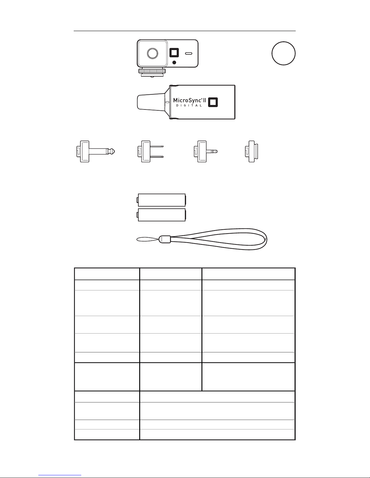
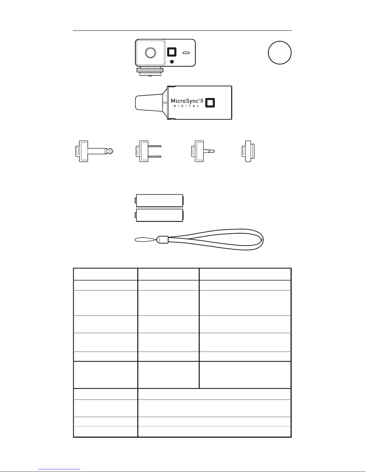
This MicroSync®II package has the following contents:
Specifications:
Transmitter Receiver
Batteries/Approx.Life CR2032 / 3 yrs 2 AA / 1 yr
Plugs Hot shoe
Interchangeable 1⁄4” mono plug,
3.5mm mono plug, two-prong plug,
and shoe mount
Ports Sub-mini phone input Sub-mini phone output 2.5 mm
2.5mm
Size 2.13 x 0.9 x 1.26” 1.42 x 0.9 x 4.17”without plug
(54 x 23 x 32 mm) attached, (36 x 23 x 106 mm)
Weight incl. Batteries 0.7 oz (20 g) 3.35 oz (95 g)
System Requirements Cameras with a Power pack or monolight with
universal hot shoe sync voltage above 3 volts and less
than 100 volts
Max Range 200 ft (60 m)
Max Sync Speed Focal plane: 1/200th of a second *
Leaf shutter: 1/350th of a second
Channels 16
Frequency 433 MHz
Transmitter
(included in kit only)
Transmitter
Battery (installed)
Receiver
Plugs
AA batteries
Lanyard
Mono Plug Two Prong Plug Mini Plug
(3.5mm)
Shoe Mount
CR2032
*Please note that maximum sync speed will vary among camera/strobe combinations and may be less.
Page 4
4
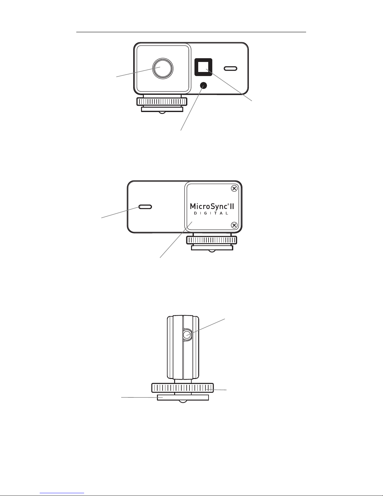
Operation at a Glance: Transmitter
Hot Foot
Slips into the
hot shoe of
most cameras.
Test Fire
Button
Press to
manually fire
strobes.
Channel Select Button
Press once and the LCD will display the
current channel. When pressed again,
channel will change to next channel.
LCD
Displays channel and
battery level. Battery
icon will flash when
battery is low.
Battery Compartment Door
Replace battery when the battery
icon on LCD flashes.
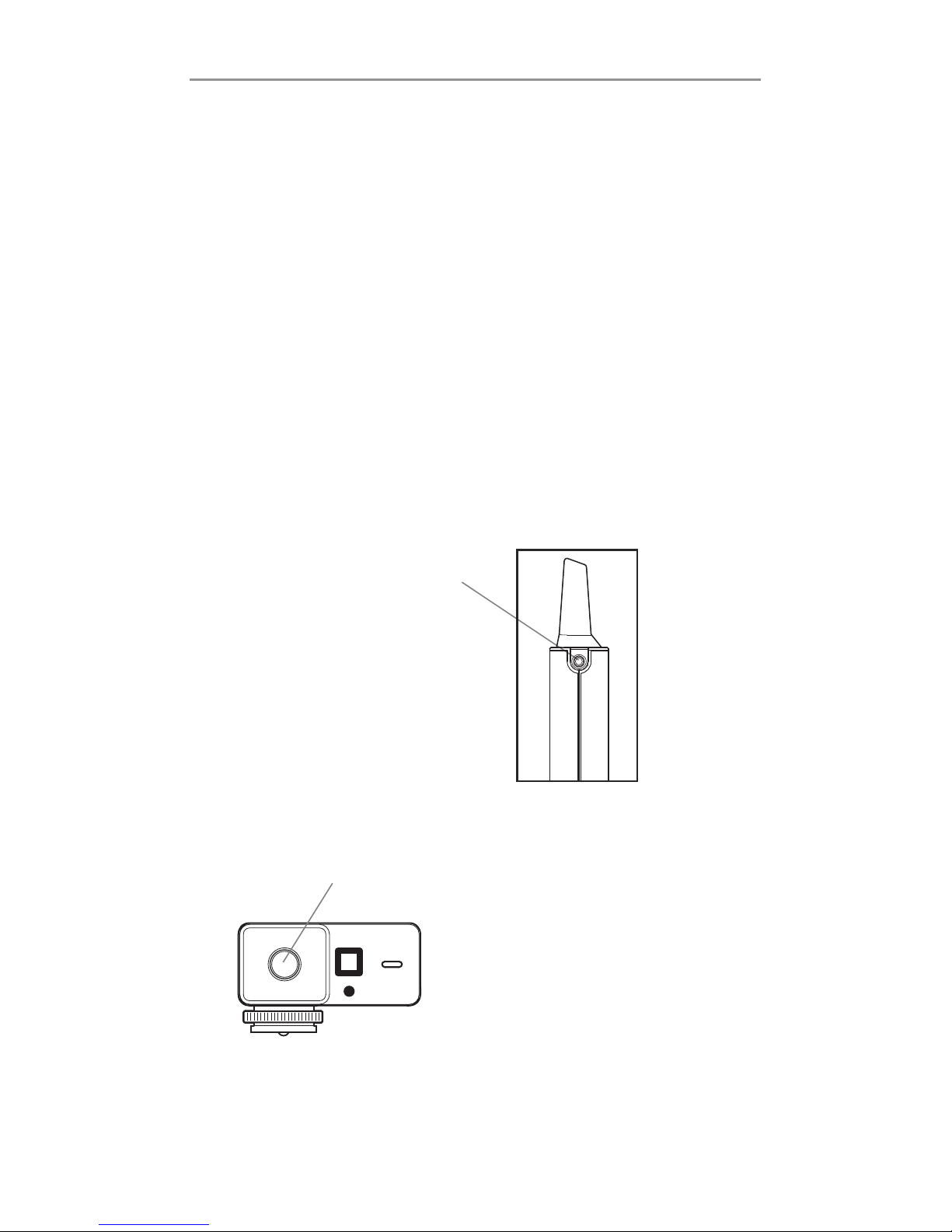
Transmitter Input
Can be used with a
sync cord to connect
the transmitter to a
camera’s sync
terminal.
Locking Ring
Used to secure the
transmitter into the
hot shoe.
LED
Flashes to
confirm
signal transmission and
channel
change.
Please Note: There are no on/off buttons on the transmitter or receiver
because they feature an automatic power management system. Both units
remain in a state of 'sleep' until the instant they are used.
Page 5
5
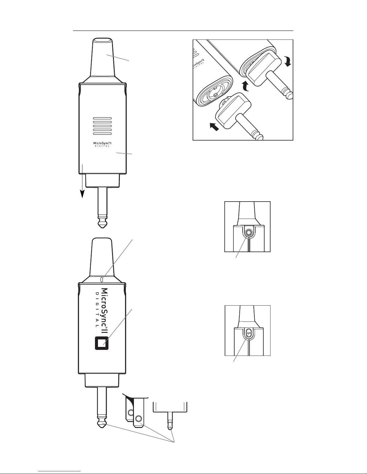
Operation at a Glance: Receiver
Antenna
For best range,
position vertically and keep
clear of metal,
concrete, and
water.
Lanyard Attachment
Can be used to hang the
receiver from a tripod or
light stand.
Battery Compartment Door
Replace batteries
when battery
icon on LCD
flashes.
Receiver Output
For use with adapter
cord or firing a camera
or strobe.
Strobe Sync Plugs
Allow receiver to be plugged directly into
most mono lights and power packs.
Slide
down
to open
LCD
Displays channel
and battery
level. Battery
icon will flash
when battery
is low.
LED
Flashes to confirm
startup, signal
reception, and
channel change
instruction from
transmitter.
Mono
Plug
Two Prong
Plug
Mini Plug
(3.5mm)
Attaching Plugs
Insert plug adapter into
receiver base and turn
clockwise to lock.
Page 6

6
Directions for Firing Strobes and Channel Operation
To Fire Strobes
To fire strobe lights using the MicroSync®II, you need a MicroSync®II transmitter
and a MicroSync®II receiver. Follow these easy steps:
1. Insert the transmitter into the hot shoe of your camera and turn your camera on.
If your camera doesn’t have a hot shoe, visit www.microsyncdigital.com to learn
how to fire strobes from cameras without a hot shoe.
2. Open the receiver’s battery compartment door by pulling down on the side of
the receiver with the grooves on it.
3. Install the two included “AA” batteries (observe the polarity of the batteries as
indicated).
4. A set of four interchangeable plugs are supplied with the MicroSync®II. Each
plug has a bayonet-type mount for attaching it to the receiver. Select the plug
type that corresponds to your strobe’s sync input. Insert plug adapter into the
receiver base and turn the plug adapter clockwise to lock (see illustration on
page 5). If the plugs supplied are not compatible with your strobe, you may be
able to connect the receiver to your strobe with a cable. Visit
www.microsyncdigital.com for information about available cables.
5. Plug the receiver into the sync socket of your power pack or monolight.
6. Shoot!
To Change or Synchronize Channels
The MicroSync®II has 16 channels. The transmitter and receiver must be on the
same channel. Both the transmitter and the receiver are set to channel 1 at the
factory. The receiver also automatically resets to channel 1 when the batteries are
removed and reinstalled.
Please note: Channels 1-4 of the MicroSync®II are compatible with channels 1-4
of the previous version of the MicroSync®and have the same sync speed and
range as the previous version of the MicroSync®. Channel 16 has been designed
with less sensitivity in order to work with strobes that produce interference. As a
result, this channel has a maximum range of approximately 20 feet.
To change or synchronize the channels, follow these steps:
1. Turn on your power pack or monolight.
2. Plug the receiver into the sync socket of the power pack or monolight.
3. While standing within three feet of the receiver, press the channel select
button on the transmitter. The transmitter’s LCD screen will display the current
channel. Press the channel select button again to select the next channel.
The transmitter will wirelessly synchronize the receiver to the last selected
channel. The receiver’s LCD screen will then display the channel selected.
Please note: This channel changing or synchronizing procedure must be done
within three feet of the receiver and within 10 seconds of plugging the receiver in
to a strobe or power pack. After 10 seconds the receiver will lock itself to the last
selected channel. This feature ensures that another MicroSync®II user cannot
inadvertently change the channel of your MicroSync®II receiver.
Page 7

7
Tips and Troubleshooting
Instant, automatic on/off power management
There are no on/off buttons on the transmitter or receiver because they feature an automatic power management system. Both units remain in a state
of 'sleep' until the instant they are used.
My MicroSync®II won’t fire
The most common reason is unsynchronized channels. Test the strobe independently to be sure it is firing. If the strobe works, but the MicroSync
®
II
doesn’t, turn the strobe off and on again with the receiver connected.
Within 10 seconds after the strobe is turned on, synchronize the channels
(transmitter must be within three feet of receiver). The transmitter’s LCD
screen will confirm the channel selection. The receiver’s LCD screen should
display the same channel.
Low Batteries
The transmitter and the receiver have a low-battery indicator on the LCD
screens. If so indicated, replace the batteries, observing polarity.
I can’t get enough range
The MicroSync®II has been tested to 200 feet (60 m). Radio reflections and
obstructions may reduce the range significantly, so observe the following
guidelines to achieve the best range: Position the receiver antenna
vertically, and as high as possible. Keep your hands from covering the
transmitter antenna. Avoid having metal, concrete, or water obstructions
between the transmitter and receiver. Relocate the receiver to avoid
possible local reflections. Moving the transmitter a few feet will often
solve the problem.
Some strobes (particularly Canon’s 580EX and 580EX II) generate interference that prevents the receiver from receiving a signal from the transmitter.
Channel 16 has been designed with less sensitivity to compensate for the
interference from these strobes. Because of the reduced sensitivity of
Channel 16, the maximum range of this channel is approximately 20 feet.
Page 8
8
Directions for Firing a DSLR
To remotely fire a DSLR
The MicroSync®II can be used to remotely fire most DSLRs that have an
electronic cable release input. To do this, you will need a camera firing cord
for your DSLR. MicroSync
®
II camera firing cords are available for most
Canon, Nikon and Pentax digital and film SLRs. For available camera firing
cords visit: www.microsyncdigital.com.
Once you obtain the proper cord for your camera, follow these
easy steps:
1. Turn your camera on.
2. Locate the electronic shutter release input on your camera.
3. Plug the corresponding end of the camera firing cord into the camera’s
electronic shutter release input.
4. Plug the cord’s sub-mini phone plug
(2.5mm) into the MicroSync
®
II
receiver’s output port.
5. Install the shoe mount adapter on to
the receiver and place it into the
camera’s hot shoe. Please note that
this adapter is not a live hot shoe; it
is only a mechanism for holding the
receiver on the camera.
6. While holding the transmitter,
press the test fire button to fire
the camera.
Please Note: For cameras in auto focus mode, you will need to press and
hold down the test fire button for a second to allow the camera to focus
and then fire.
Page 9
9
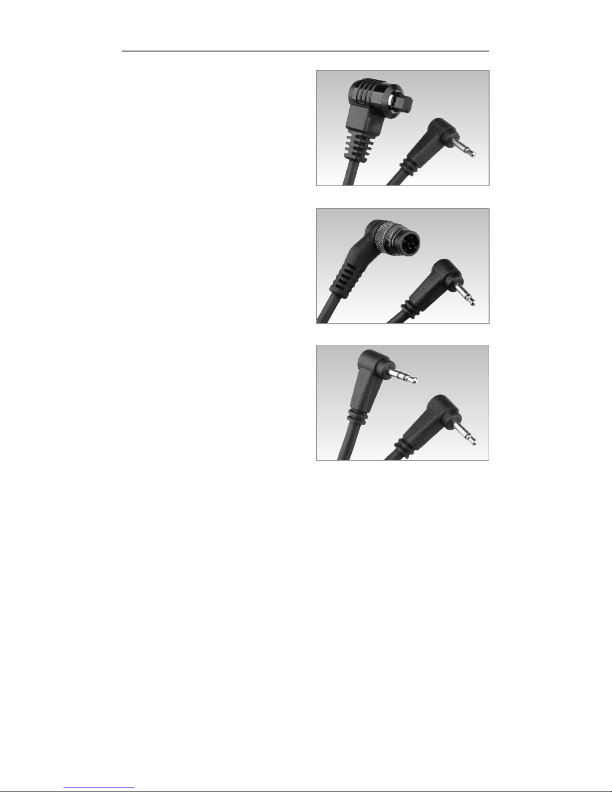
Camera Firing Cords
For Canon Pro DSLRs
Model VMC115
Works with Canon 10D, 20D, 30D,
40D, 50D, 5D, 5D Mark II, 7D,
1D Mark II, 1D Mark II N, 1D Mark III,
1D Mark IV, 1Ds Mark II, 1Ds Mark III,
1V, 1VHS, and EOS 3 SLRs.
For Nikon DSLRs
Model VMC116
Works with Nikon D1, D1H, D1X,
D2H, D2Hs, D2X, D2Xs, D3, D3S,
D3X, D200, D300, D300s, D700,
F100, F5, F6, N90 and N90s SLRs.
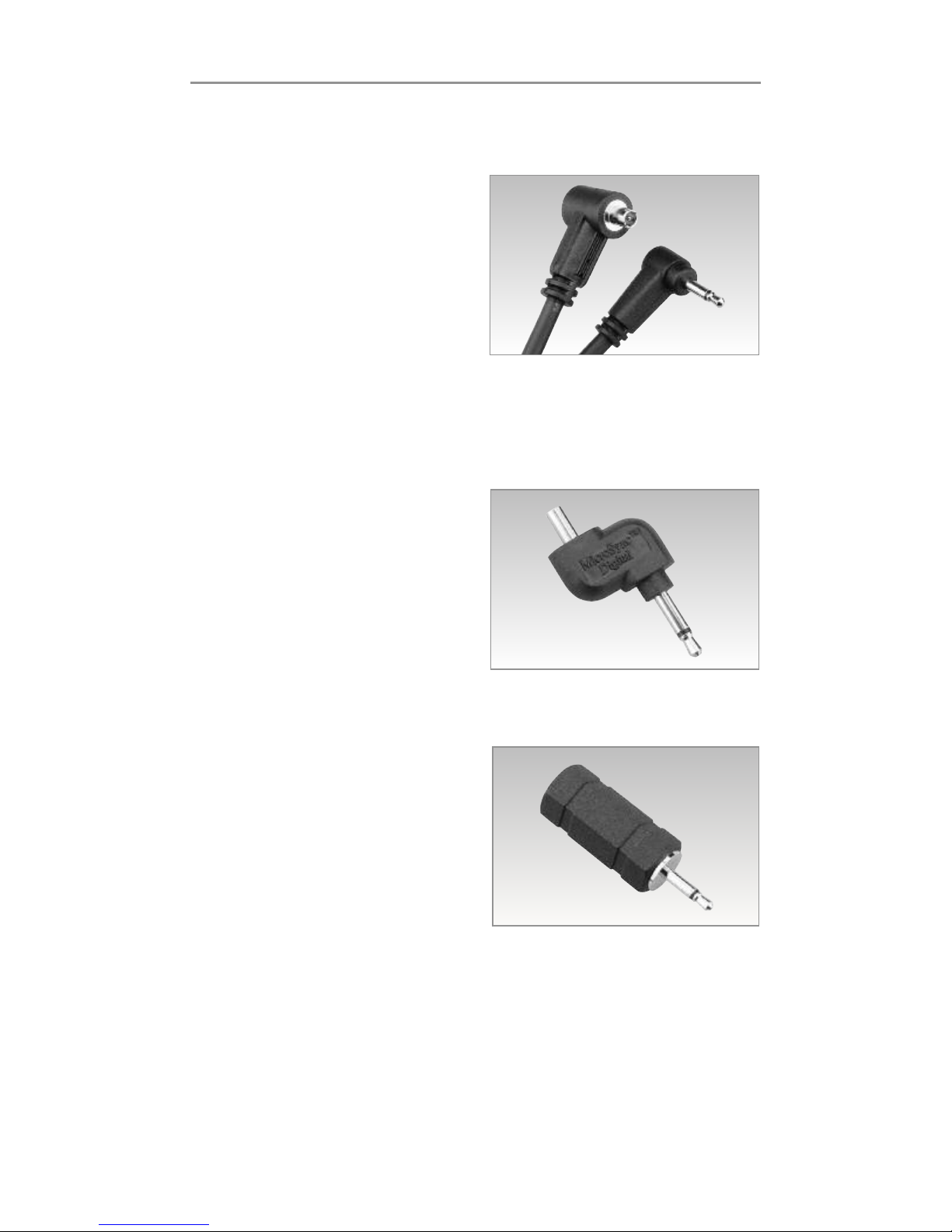
For Canon Digital Rebel
and Pentax DSLRs
Model VMC117
Works with Canon 60D, EOS Digital
Rebel (300D), Digital Rebel T1i
(500D), Digital Rebel T2i (550D),
Digital Rebel T3 (1100D), Digital
Rebel T3i (600D), Digital Rebel XS
(1000D), Digital Rebel Xsi (450D),
Digital Rebel XT (350D), and Digital Rebel XTi (400D) DSLRs. Also works
with Pentax K-5, K-7, K-r, K-x, K10D, K20D, K100D, K110D, K200D, *istD,
*istDL, *istDS, and *istDS2 DSLRs.
For a complete list of compatible DSLRs,
visit www.microsyncdigital.com.
Page 10
10
Sync Cords and Adapters
To expand the utility of the MicroSync®II system, we offer the
following sync cords and adapters (sold separately).
PC Cord for MicroSync®II
Model VMC112
Common Uses:
• Remotely fire a PC terminal-
equipped flash (such as Canon’s
580EX II and Nikon’s SB-26,
SB-28, SB-80, SB-800 or SB-900).
• Fire a remote light and a hot shoe
mounted flash simultaneously.
• Fire strobes remotely using a PC terminal-equipped light meter.
• Fire strobes remotely from PC terminal-equipped medium format
cameras or lenses.
Universal Sync Cord Adapter
for MicroSync
®
II
Model VMC113
This adapter allows you to plug your
strobe’s sync cord into the MicroSync
®
II receiver.
Note: This adapter is only necessary
for strobes that do not have either
the
1
⁄4” mono plug, mini (3.5mm) plug
or two prong plug sync inputs.
Sync Cord Reducer for
MicroSync
®
II
Model VMC114
Mini (3.5mm) to Sub-mini (2.5mm)
Makes sync cords with mini phone
(3.5mm) plugs compatible with
MicroSync
®
II sub-mini phone
(2.5mm) ports.
For instructions on the use of these sync cords
and adapters, visit www.microsyncdigital.com.
Page 11

11
2 YEAR LIMITED WARRANTY
This MicroSync®II product is fully warranted to the original retail purchaser
against defects in materials and workmanship for 2 years, except as noted
below. This warranty shall apply to those products which have been put to the
use intended by the manufacturer and does not apply to products
damaged by misuse or neglect. Service under this warranty is available by forwarding the product, freight prepaid, with dated proof of purchase to Tamrac’s
Service Department, 9240 Jordan Avenue, Chatsworth, CA 91311, USA.
(Note: MicroSync
®
II products purchased outside of the United States
should be returned to the place of purchase or to the Tamrac distributor in that country for warranty coverage.) If our inspection finds the
product to be defective in either materials or workmanship, we will repair or
replace it at our option and return it freight collect. This
procedure shall be the exclusive remedy for any breach of this limited warranty. Tamrac shall not be liable for consequential or incidental damages. There
are no other expressed or implied warranties, including merchantability or fitness for particular purpose, that extend beyond the terms of this limited warranty. This warranty gives you specific legal rights, and you may also have
other specific legal rights which may vary from state to state.
Warning
!! Do not plug the two-prong plug of the MicroSync®II receiver into
a wall socket or extension cord. The two-prong adapter is to be plugged
into flash units with the corresponding two-prong receptacle only!!
Plugging the receiver into a wall socket is not an intended use. Doing so will
permanently damage the receiver and will void the warranty.
Warranty
Modifications made to the product, unless expressly approved by
Tamrac, Inc., could void the user’s authority to operate the equipment.
FCC ID: UJYMS0200
This device complies with Part 15 of the FCC Rules. Operation is subject to
the following two conditions: (1) This device may not cause harmful
interference, and (2) this device must accept any interference received,
including interference that may cause undesired operation.
EC Conformity declaration
MicroSync®II complies with the spectrum and electromagnetic regulations as
provided by the European Community (EMV-RL 2004/108/EG). A declaration of
conformity might be obtained from the importer in your country.
Page 12

12
Inhaltsverzeichnis
Englisch . . . . . . . . . . . . . . . . . . . . . . . . . . . . . . . . . . . . . . . . . . . . . . . . . . . . . . . 2
Deutsch
MicroSync®II Packungsinhalt . . . . . . . . . . . . . . . . . . . . . . . . . . . . . . . . . . 13
Kurzbeschreibung: Sender . . . . . . . . . . . . . . . . . . . . . . . . . . . . . . . . . . . . . 14
Kurzbeschreibung: Empfänger . . . . . . . . . . . . . . . . . . . . . . . . . . . . . . . . . . 15
Auslösen von Blitzgeräten . . . . . . . . . . . . . . . . . . . . . . . . . . . . . . . . . . . . . 16
Ändern oder Synchronisieren der Kanäle. . . . . . . . . . . . . . . . . . . . . . . . . . 16
Hinweise und Fehlerbehebung. . . . . . . . . . . . . . . . . . . . . . . . . . . . . . . . . . 17
Fernauslösung einer digitalen SLR-Kamera . . . . . . . . . . . . . . . . . . . . . . . . 18
Kameraauslösekabel fur verschiedene Kameras . . . . . . . . . . . . . . . . . . . . 19
Synchronisationskabel und-adapter . . . . . . . . . . . . . . . . . . . . . . . . . . . . . 20
Garantieerklärung. . . . . . . . . . . . . . . . . . . . . . . . . . . . . . . . . . . . . . . . . . . . 21
Spanisch. . . . . . . . . . . . . . . . . . . . . . . . . . . . . . . . . . . . . . . . . . . . . . . . . . . . . . 22
Französisch . . . . . . . . . . . . . . . . . . . . . . . . . . . . . . . . . . . . . . . . . . . . . . . . . . . 32
Wichtiger Hinweis zu Batterien und Akkus
Das nebenstehende Symbol weist Sie darauf hin, dass ausgediente Batterien und
Akkus im Interesse des Umweltschutzes weder zerlegt noch verbrannt, noch im
Hausmüll entsorgt werden dürfen, sondern ausschließlich an den dafür
eingerichteten Sammelstellen abgegeben werden müssen, z.B. dort, wo
Sie neue Batterien und Akkus kaufen können, oder an Sammelstellen
der öffentlich-rechtlichen Entsorger. Recycling schont die Natur und Ihre
Gesundheit.
EG-Konformitätserklärung
Für den Tamrac MicroSync®II wird bestätigt, dass er den Anforderungen entspricht,
die in der Richtlinie des Rates zur Angleichung der Rechtsvorschriften der Mitgliedstaaten über die elektromagnetische Verträglichkeit und das Funkspektrum (EMV-RL
2004/108/EG) festgelegt sind. Eine Konformitätserklärungs-Kopie können Sie
anfordern bei:
HapaTeam Handelsges. mbH, Goethestr. 11, D-85386 Eching
Page 13
13
Diese MicroSync
®
II-Packung enthält folgende Teile:
Technische Daten:
Sender Empfänger
Batterie/Lebensdauer CR2032 / ca. 3 Jahre 2 Mignon-Zellen / ca. 1 Jahr
Geräteanschluss Aufsteckfuß
auswechselbar: Mono-Klinke ¼“,
bzw.- befestigung Mini-Klinke 3,5 mm, Doppelstift-
Stecker oder Kamera-Aufsteckfuß
Weitere Anschlusse
Sub-Mini-Klinkenbuchse
Sub-Mini-Klinkenbuchse 2,5 mm
2,5 mm (Eingang) (Ausgang)
Abmessungen 54 x 23 x 32 mm 36 x 23 x 106 mm (ohne einen der
auswechselbaren Steckanschlusse)
Gewicht inkl. Batterie(n) 20 g 95 g
System-Voraussetzung Kamera mit u blichem Generator- oder Kompaktblitzgerät
Aufsteckschuh mit mit Synchronisationsspannung
Mittenkontakt zwischen 3 Volt und 100 Volt
Reichweite ca. 60 m
kürzeste Verschlusszeit Schlitzverschluss: 1/200 s*
zur Synchronisation Zentralverschluss: 1/350 s
Kanäle 16
Sendefrequenz 433 MHz
Sender
(nur im Set enthalten)
Batterie für
Sender (eingelegt)
Empfänger
Steckanschlüsse
Mignon-Zellen
(Typ AA, LR06)
Handschlaufe
Mono-Klinke Doppelstift-
Stecker
Mini-Klinke
(3,5 mm)
Aufsteckfuß
(ohne el. Kontakte,
nur zur Befestigung)
CR2032
* Die kürzeste Verschlusszeit kann je nach Kamera-Blitz-Kombination auch kürzer sein.
Page 14

14
Kurzbeschreibung: Sender
Aufsteckfuß
Lässt sich in den
Aufsteckschuh der
meisten Kameras
stecken.
TestAuslöser
Zum manuellen
Blitzauslöse
hier drücken.
Taste zur Kanalauswahl
Bei einmaligem Drücken wird im LCD-Feld
der aktuelle Kanal angezeigt; bei wiederholtem
Drücken wird zum jeweils nächsten Kanal gewechselt.
LCD
Anzeige des Kanals und
des Batteriezustands;
das Batteriesymbol blinkt
bei schwacher Batterie.
Batteriefach-Abdeckung
Wenn das Batteriesymbol im LCD-Feld
blinkt, ist die Batterie zu erneuern.
Eingangsbuchse
Hier ist bei fehlendem
Mittenkontakt ein
Synchronkabel zur
Kamera-Synchronbuchse
anzuschließen.
Arretierring
Damit kann der im Aufsteckschuh eingesteckte
Sender gesichert werden.
LED
Blinkt zur
Bestätigung
eines ausgesandten
Signals und
eines Kanalwechsels.
Achtung: Es gibt weder am Sender noch am Empfänger einen Ein- oder
Ausschalter, weil das Stromversorgungssystem automatisch reagiert.
Beide Geräte bleiben bis zur Benutzung in einem Bereitschaftsmodus.
Page 15

15
Kurzbeschreibung: Empfänger
Antenne
Fur besten
Empfang
und größte
Reichweite
möglichst
senkrecht
stellen und
von Metall,
Beton und
Wasser
fernhalten.
Batteriefach-
Abdeckung
Wenn das Batterie-
symbol im LCD-Feld
blinkt, ist die Batterie
zu erneuern.
Steckanschlusse zum Blitzgerät
Damit ist der Empfänger direkt an einen
Generator-/Kompaktblitz anschließbar.
Zum
Öffnen
nach
unten
schieben
Handschlaufen-Öse
Zum Aufhängen des
Empfängers an ein Stativ
oder Lampenstativ.
Ausgangsbuchse
Fur Adapterkabel zum
Auslösen einer Kamera
oder eines Blitzgeräts.
LCD
Kanal- und
Batteriezustands-
anzeige; das
Batteriesymbol
blinkt bei zu
schwacher Batterie.
LED
Blinkt zur Bestätigung
von Blitzbereitschaft,
Signalempfang sowie
Befehlsempfang
vom Sender zum
Kanalwechsel.
Mono-
Klinke
Doppelstift-
Stecker
Mini-Klinke
(3,5 mm)
Steckanschlussbefestigung
In den Empfängerboden
einstecken und im
Uhrzeigersinn drehen
.
Page 16

16
Anleitung zum Blitzauslösen und zur Kanalumschaltung
Auslösen von Blitzgeräten
Um ein Blitzgerät über einen MicroSync®II auszulösen, brauchen Sie einen MicroSync®II-Sender und einen MicroSync®II-Empfänger. Folgen Sie dieser Anweisung:
1. Stecken Sie den Sender in den Kamera-Aufsteckschuh und schalten Sie die
Kamera ein. Falls Ihre Kamera keinen Aufsteckschuh hat, informieren Sie sich
bitte auf der Internetseite
www.microsyncdigital.com,
wie vorzugehen ist.
2. Öffnen Sie das Batteriefach des Empfängers, indem Sie die Seitenwand desGehäuses mit der gerillten Fläche nach unten schieben.
3. Legen Sie die beiden mitgelieferten Mignon-Zellen ein; achten Sie dabei auf
dierichtige Polarität (+ und -), wie es dort angegeben ist.
4. Im Lieferumfang des
MicroSync®II
finden Sie vier Steckanschlüsse für denEmpfänger, die über ein Bajonett zu befestigen sind. Wählen Sie den zum Auslösekontakt Ihres Blitzgeräts passenden Steckanschluss. Stecken Sie ihn an den
Empfänger, indem Sie die Pfeile auf der Montageplatte und am Steckanschluss
in Deckung bringen und dann den Steckanschluss im Uhrzeigersinn bis zum Einrasten drehen. Falls keiner der vier Steckanschlüsse mit Ihrem Blitzgerät kompatibel ist, können Sie den Empfänger per Kabel mit dem Blitzgerät verbinden.
Informieren Sie sich auf www.microsyncdigital.com über die lieferbaren Kabel.
5. Stecken Sie den Empfänger an die Synchronisationsbuchse Ihres Blitzgeräts.
6. Sie können jetzt mit kabelloser Blitzauslösung fotografieren!
Ändern oder Synchronisieren der Kanäle
Ihr MicroSync®II bietet 16 Übertragungskanäle. Die Kanäle 1 bis 4 sind mit den vier
Kanälen 1 bis 4 des früheren MicroSync®-Systems kompatibel, eignen sich für die
gleichen Verschlusszeiten und haben dieselbe Reichweite wie diese. Um mit dem MicroSync®II arbeiten zu können, mussen Sie dafur sorgen, dass Sender und
Empfänger auf denselben Kanal eingestellt sind. Werkseitig sind beide auf Kanal 1
eingestellt. Der Empfänger stellt sich, wenn die Batterie gewechselt wird, stets automatisch wieder auf Kanal 1 ein (was dann gegebenenfalls geändert werden muss).
Kanal 16 arbeitet mit reduzierter Empfindlichkeit (und hat darum nur ca. 6 m Reichweite), um mit Blitzgeräten benutzt werden zu können, die Störungen verursachen.
Zum Ändern und Synchronisieren des geänderten Kanals gehen Sie wie folgt vor:
1. Schalten Sie das Blitzgerät bzw. dessen Generator ein.
2. Stecken Sie den Empfänger an die Synchronisationsbuchse den Blitzgeräts.
3. Bleiben Sie im Umkreis von ca. 1 m vom Empfänger und drücken Sie am Sender
die Taste zur Kanalwahl. Im LCD-Feld des Senders wird dann der aktuell
eingestellte Kanal angezeigt. Drücken Sie nun die Kanalwahltaste des Senders
so oft, bis Sie den gewunschten Kanal erreicht haben. Dabei wird zugleich der
Empfänger kabellos mit dem jeweils zuletzt eingestellten Kanal synchronisiert.
Im LCD Fenster des Empfängers wird ebenfalls der eingestellte Kanal angezeigt.
Bitte beachten Sie:
Die Kanalwahl/Synchronisation muss innerhalb von 10 Sekunden
nach dem Anstecken des Empfängers an die Blitzgerät-Synchronisationsbuchse
des Blitzgeräts und aus weniger als 1 m Abstand des Senders vom Empfänger erfolgen. Nach 10 Sekunden wird die aktuelle Kanaleinstellung des Empfängers fest
gespeichert. Das gewährleistet, dass später ein anderer MicroSync®II-Benutzer mit
seinem Sender nicht ungewollt den an Ihrem Empfänger eingestellten Kanal ändert.
Page 17

17
Hinweise und Fehlerbehebung
Schnellreagierende automatische Ein- und Ausschaltung
Es gibt weder am Sender noch am Empfänger Ein- oder Ausschalter, weil
beide mit einem automatischen Ein-und-Ausschalt-System ausgestattet
sind. Beide bleiben bis zu dem Moment im Bereitschaftsmodus (Standby), in
dem sie benutzt werden.
Mit meinem MicroSync®II lässt sich nicht auslösen
Der häufigste Grund sind unsynchronisierte Kanäle. Prüfen Sie daher zunächst,
ob das Blitzgerät selbst (unabhängig vom
MicroSync
®
II) blitzen kann. Wenn es
funktioniert, mit dem
MicroSync
®
II aber nicht, schalten Sie das Blitzgerät mit
angestecktem Empfänger
MicroSync
®
II aus und wieder ein. Synchronisieren
Sie dann innerhalb von 10 Sekunden, wie links beschrieben, die Kanäle von
Sender und Empfänger (wobei ihr Abstand voneinander kleiner als 1m sein
muss). Das LCD-Feld des Empfängers zeigt den Kanal zur Bestätigung an; es
muss derselbe Kanal wie im LCD-Feld des Senders sein.
Die Batterie ist zu schwach
Sowohl der Sender als auch der Empfänger zeigt bei zu schwacher Batterie
im jeweiligen LCD-Feld ein blinkendes Batteriesymbol an. Erneuern Sie die
Batterie(n), sobald eine solche Warnung erscheint. Beachten Sie die richtige
Polarität (+ und -).
Die Reichweite ist zu gering
Wir haben die
MicroSync
®
II-Geräte bei 60m Abstand getestet. Reflexionen
der Funkwellen und Hindernisse können aber die Reichweite merklich
verkürzen. Beachten Sie daher die folgenden Regeln, um die bestmögliche
Reichweite zu erzielen: Die Antenne des Empfängers sollte sentrecht und so
hoch wie möglich stehen. Decken Sie nicht mit Ihren Händen die Antenne
des Senders ab. Sorgen Sie dafür, dass sich keine Hindernisse aus Metall,
(Stahl-) Beton oder Wasser zwischen Sender und Empfänger befinden.
Ändern Sie gegebenenfalls die Position der Empfängers, um FunkwellenReflexionen zu vermeiden oder ihnen auszuweichen. Manchmal genügt
schon eine Ortsveränderung um weniger als einen Meter, um solche
Empfangsprobleme zu beheben.
Manche Blitzgeräte (speziell die Modelle Canon 580EX und 580EX II) erzeugen
Störungen, die den Empfänger daran hindern, die Signale des Senders zu
empfangen. Der Kanal 16 des Empfängers wurde deshalb mit reduzierter
Empfindlichkeit konzipiert, um auf die von solchen Blitzgeräten ausgehenden
Störungen nicht zu reagieren. Wegen dieser verminderten Empfindlichkeit
auf Kanal 16 kann aber mit diesem Kanal nur eine kürzere Reichweite von ca.
6m erzielt werden.
Page 18

18
Anleitung zum Auslösen einer (digitalen) SLR-Kamera
Fernauslösung einer digitalen SLR-Kamera
Ihr MicroSync®II kann auch zur Fernauslösung der meisten digitalen und
einiger analoger SLR-Kameras benutzt werden, die eine Buchse fur ein elek-
trisches Auslösekabel haben. Dazu benötigen Sie ein zu Ihrer SLR-Kamera
passendes Kamera-Auslösekabel (siehe rechts). Solche Kabel sind fur die
meisten Canon-, Nikon- und Pentax-SLR-Kameras erhältlich. Informieren Sie
sich uber die aktuell verfugbaren Kamera-Auslösekabel auf der Internetseite
www.microsyncdigital.com.
Nachdem Sie sich das fur Ihre Kamera geeignete Kamera-Auslösekabel
beschafft haben, folgen Sie diesen einfach auszufuhrenden Schritten:
1. Stecken Sie den Empfänger mit dem unten angebrachten Aufsteckfuß* auf
den Aufsteckschuh der Kamera und schalten Sie Ihre Kamera ein.
2.
Sehen Sie nach, wo sich die Buchse fur das elektrische Auslösekabel befindet.
3. Stecken Sie das dazu passende Ende des Kamera-Auslösekabels in die
Buchse fur das elektrische Auslösekabel.
4. Stecken Sie den 2,5-mm-Mini-Klinkenstecker am anderen Kabelende in die
entsprechende Ausgangsbuchse des MicroSync
®
II-Empfängers.
5. Befestigen Sie den
Aufsteckfuß
an
den Aufsteckschuh der Kamera. Bitte
beobachtigen Sie dass der
Aufsteck-
fuß
nicht ein aktiver Adapter ist aber
eine Methode um der Empfänger auf
die Kamera zu setzen.
6. Nehmen Sie den MicroSync
®
II-
Sender in die Hand und drucken Sie
zum Auslösen der Kamera die
seitliche Test-Auslösetaste des
Senders.
Bitte beachten Sie: Wenn sich Ihre Kamera im Autofokus-Modus befindet,
muss die Test-Auslösetaste etwa eine Sekunde lang gedruckt gehalten werden,
damit die Kamera erst automatisch scharfstellen kann, bevor ausgelöst wird.
* Achtung: Der Aufsteckfuß des Empfängers
hat keine elektrischen Kontakte, sondern
dient nur zur Befestigung an der Kamera!
Page 19

19
Kamera-Auslösekabel
Modell VMC115
für Canon-Pro-SLR-Kameras
Passt zu Canon-SLR-Kameras 10D,
20D, 30D, 40D, 50D, 5D, 5D Mark II,
7D, 1D Mark II, 1S Mark II N, 1D
Mark III, 1D Mark IV, 1Ds Mark II, 1Ds
Mark III, 1V, 1VHS und EOS 3.
Modell VMC116
für Nikon-SLR-Kameras
Passt zu Nikon-SLR-Kameras D1,
D1H, D1X, D2H, D2Hs, D2X, D2Xs,
D3, D3S, D3X, D200, D300, D300s,
D700, F100, F5, F6, N90 und N90s.
Modell VMC117
für Canon-Amateur-SLRund Pentax-SLR-Kameras
Passt zu Canon 60D, 300D (EOS
Digital Rebel), 350D (Digital Rebel
XT), 400D (Digital Rebel XTi), 450D
(Digital Rebel Xsi), 500D (Digital
Rebel T1i), 550D (Digital Rebel T2i),
600D (Digital Rebel T3i), 1000D (Digital Rebel XS), 1100D (Digital RebelT3).
Passt außerdem auch an Pentax K-r, K-x, K-5, K-7, K10D, K20D, K100D,
K110D,K200D, *istD, *istDL, *istDS und *istDS2.
Eine stets aktuelle Liste aller kompatiblen SLR-Kameras
finden Sie auf der Internetseite
www.microsyncdigital.com.
Page 20

20
Synchronisationskabel und-adapter
Zur Erweiterung der Anwendungsmöglichkeiten des MicroSync®II-Systems
bieten wir die als separates Zubehör erhältlichen Synchronisationskabel undadapter an.
Modell VMC112
Synchronisationskabel
fur MicroSync
®
II
Anwendungsbereiche:
• Zur Fernauslösung eines Blitzgeräts mit
der ublichen PC-Blitzbuchse („Blitznip-
pel“), z.B. Canon 580EX II oder Nikon
SB-26, SB-28, SB-80, SB-800 oder
SB-900.
• Zur gleichzeitigen Fernauslösung eines
Blitzgeräts, wenn ein anderes Blitzgerät auf dem Kamera-Au steckschuh über
dessen Mittenkontakt ausgelöst wird.
• Zur Fernauslösung eines Blitzgeräts zur Blitzmessung mit einem über seine PC-
Blitzbuchse mit dem Blitzgerät zu synchronisierenden Blitzbelichtungsmesser.
• Zur Fernauslösung eines Blitzgeräts von einer Mittelformatkamera ohne Mittenkon-
takt-Aufsteckschuh über deren Kamera- oder Objektiv-PC-Blitzbuchse.
Modell VMC113
SynchronisationskabelAdapter fur MicroSync
®
II
Der Adapter ermöglicht den Anschluss
des MicroSync®II-Empfängers an ein
Blitzgerät über ein normales Synchronisa-
tionskabel. Das ist erforderlich, wenn
das Blitzgerät weder eine ¼“-Klinkenbuchse noch eine 3,5-mm-Mini-Klinkenbuchse,
noch eine Doppelstift-Buchse hat, über die der Empfänger direkt ans
Blitzgerät angesteckt werden könnte.
Modell VMC114
Reduzieradapter von 3,5 mm-
auf 2,5-mm-Klinkenstecker
fur MicroSync
®
II
Damit kann ein Synchronisationskabel
mit 3,5-mm-Mini-Klinkenstecker an die
2,5-mm-Sub-Mini-Klinkenbuchse des
MicroSync®II
-Empfängers angeschlossen
werden.
Eine Anleitung fur den richtigen Einsatz dieses Synchronkabels und dieser Adapter
finden Sie auf der Internetseite
www.microsyncdigital.com
Page 21

An diesem Produkt vorgenommene Änderungen, die nicht ausdrucklich von
Tamrac Inc. genehmigt worden sind, können den Verlust der Zulassung zum
Betrieb dieser Funkanlage zur Folge haben.
FCC ID: UJYMS0200
Dieses Gerät erfüllt die Bedingungen von Absatz 15 der FCC-Regeln (FCC =
Federal Communications Commission). Ihr Betrieb unterliegt den folgenden
Bedingungen: (1) Dieses Gerät darf keine schädlichen Störungen verursachen
und (2) es muss alle empfangenen Störungen akzeptieren, auch wenn sie
eventuell zu unerwarte-tem Verhalten seiner Funktionen führen.
21
2 Jahre Herstellergarantie
Der Erstkäufer dieses MicroSync®II-Geräts erhält eine 2-Jahres-Garantie ab Kaufdatum, welche bei Defekten die Material- und Arbeitszeitkosten abdeckt, wenn die weiter
unten angegebenen Bedingungen erfullt sind. Diese Garantie erstreckt sich nur auf
Produkte, die bestimmungsgemäß und unter Beachtung dieser Bedienungsanleitung
eingesetzt wurden, und gilt nicht bei Beschädigungen durch falsche Bedienung oder
Missachtung der ublichen Vorsichtsmaßnahmen. Um die Garantieleistung (Reparatur
oder Ersatz) innerhalb der USA in Anspruch zu nehmen, ist das defekte Gerät mit einer
Beschreibung des Fehlers oder Schadens und einer Rechnungskopie als Nachweis des
Kaufdatums einzusenden an: Tamrac Service Department, 9240 Jordan Avenue,
Chatsworth, CA 91311, USA. Wenn Sie Ihr MicroSync®II-Gerät außerhalb der USA
gekauft haben, ist das defekte Gerät zur Einforderung der Garantieleistung ebenfalls
mit einer Beschreibung des Fehlers oder Schadens sowie einer Rechnungskopie dort
abzugeben, wo Sie das Gerät gekauft haben, oder an die Tamrac-Vertretung Ihres
Landes zu senden. Wenn sich bei unserer Prufung zeigt, dass das Gerät aufgrund
eines Material- oder Fabrikationsfehlers defekt ist, werden wir es nach eigenem Ermessen reparieren oder ersetzen und unfrei an Sie zuru cksenden. Dieses Verfahren
gilt grundsätzlich fur alle durch diese Garantie abgedeckten Defekte. Tamrac kann nicht
fur sonstige Begleit- und Folgeschäden haftbar gemacht werden. Daruber hinaus gibt
es keine stillschweigenden oder ausdrucklichen Garantiezusagen, die u ber den Inhalt
dieser Garantieerklärung hinausgehen, auch keine vermeintlich marktu blichen oder zur
Eignung fur spezielle Anwendungen. Diese Garantieerklärung sichert Ihnen gewisse
Rechte, die eventuell gemäß den gesetzlichen Bestimmungen Ihres Landes noch durch
weitere Rechte ergänzt werden können.
Achtung - Gefahr!
Stecken Sie den Doppelstift-Stecker, der genauso aussieht wie ein amerikanischer
Netzstecker, niemals in eine entsprechende Netzsteckdose oder an ein entsprechendes Netz-Verlängerungskabel – der Empfänger wurde einen Totalschaden er-
leiden und die Garantie erlöschen!Der Doppelstift-Stecker darf nur in die entsprechende Synchronisationsbuchse von Studioblitz-Generatoren eingesteckt werden.
Garantieerklärung
Page 22

22
Indice
Inglés. . . . . . . . . . . . . . . . . . . . . . . . . . . . . . . . . . . . . . . . . . . . . . . . . . . . . . . . . . 2
Alemán . . . . . . . . . . . . . . . . . . . . . . . . . . . . . . . . . . . . . . . . . . . . . . . . . . . . . . . 12
Español
Contenido de MicroSync®II . . . . . . . . . . . . . . . . . . . . . . . . . . . . . . . . . . . 23
Funcionamiento: transmisor . . . . . . . . . . . . . . . . . . . . . . . . . . . . . . . . . . . . 24
Funcionamiento: receptor. . . . . . . . . . . . . . . . . . . . . . . . . . . . . . . . . . . . . . 25
Disparar flashes . . . . . . . . . . . . . . . . . . . . . . . . . . . . . . . . . . . . . . . . . . . . . 26
Cambiar o sincronizar canales . . . . . . . . . . . . . . . . . . . . . . . . . . . . . . . . . . 26
Consejos y solución de problemas . . . . . . . . . . . . . . . . . . . . . . . . . . . . . . . 27
Disparar una cámara digitral . . . . . . . . . . . . . . . . . . . . . . . . . . . . . . . . . . . 28
Cables para disparar la cámara . . . . . . . . . . . . . . . . . . . . . . . . . . . . . . . . . 29
Cables sync y Adaptadores. . . . . . . . . . . . . . . . . . . . . . . . . . . . . . . . . . . . . 30
Garantía . . . . . . . . . . . . . . . . . . . . . . . . . . . . . . . . . . . . . . . . . . . . . . . . . . . 31
Francés . . . . . . . . . . . . . . . . . . . . . . . . . . . . . . . . . . . . . . . . . . . . . . . . . . . . . . 32
Declaración de la conformidad de la Comunidad Europeo
MicroSync®II se conforma con el espectro y las regulaciones electromagnéticas
en la manera prevista por la Comunidad Europea (EMV-RL 2004/108/EG.). Una
declaración de la conformidad se pudo obtener del importador en su país.
Page 23

23
Este caja MicroSync®II contiene:
Especificaciones:
Transmisor Receptor
Baterías/Duración
CR2032 / 3 años 2 AA / 1 año
Conexiones Zapata
1⁄4” mono intercambiable,
3,5mm mono, de 2 patas, y zapata
Puertos Entrada teléfono salida teléfono sub-mini t 2.5mm
sub-mini 2,5mm
Tamaño 54 x 23 x 32mm 36 x 23 x 106mm sin conexión
Peso (con baterías) 20 g 95 g
Requerimientos Cámaras con Power pack o flash con voltage
del sistema zapata universal superior a 3 V e inferior a 100 V.
Alcance Max 60 m
Velocidad máx. Plano Focal plane: 1/200 de segundo *
Obturador: 1/350 de segundo
Canales 16
Frecuencia 433 MHz
Transmisor
(sólo con el kit)
Receptor
Conectores
2 baterías AA
Cordón
Conector
mono
Conector de
doble patilla
Conector Mini
Plug (3,5mm)
Conector
Zapata
Transmisor
Battería
(instalado)
CR2032
*La velocidad máxima variará dependiendo de las combinaciones de camara y flash y podría ser inferior
a lo indicado.
Page 24

24
Funcionamiento: transmisor
Conectador
de la zapata
Ajustes en la
zapata de las
mayoría de las
cámaras.
Botón de
testeo de
disparo
Presionar
manualmente
para disparar
los flashes.
Selector de canal
Presione una vez y verá el canal
actual en el LCD. Presione otra vez y
cambiará al siguiente canal.
LCD
Muestra el canal y
La carga de la batería.
Cuando está baja
parpadea el icono de
batería.
Compartimento de baterías
Sustituya las baterías cuando el icono
del LCD parpadee.
Entrada del transmisor
Se puede usar con un
cable sync para conectar
el transmisor al terminal
de la cámara.
Anillo de cierre
Asegura el transmisor en la zapata.
EL LED
parpadea
para confirmar
la transmisión
y el cambio
de canal.
Importante: No hay botones de encendido/apagado ni en el receptor ni
en el transmisor porque el sistema es automático. Ambas unidades
quedan en “espera” hasta que se utilizan.
Page 25

25
Funcionamiento: receptor
Antena
Para mejorar el
alcance sitúela
verticalmente y
mantégase lejos
de metal,
cemento y agua.
Cordón
Para utilizar cuelgue el
receptor de un trípod.
Compartimento
de baterías
Sustituya las
baterías cuando
parpadee el icono
en el LCD.
Salida Receptor
Ara usar con cable adaptador
o para disparar una cámara o
un flash.
Conexiones
Permiten conectar el receptor a
luces mono y power packs.
Respale
abajo
para
abrir
LCD
Muestra el canal
y el nivel de
batería. El icono
de la batería
parpadeará
cuando el nivel
sea bajo.
LED
Parpadea para
confirmar la
recepción,
canal, y baja
batería.
Conector
Mono
Conector de
doble patilla
Conector
Mini Plug
(3.5mm)
Conexiones
Inserte el adaptador en la
base del receptor y gírelo
en el sentido de las agujas
del reloj.
Page 26

26
Instrucciones Para Disparar Flashes// Canales
Para disparar flashes
Para disparar flashes con MicroSync®II, se necesitan un transmisor y un receptor
MicroSync®II yseguir estos pasos:
1. Inserte el transmisor en la zapata de la cámara y encienda ésta..
Si la cámara no tiene zapata, visite www.microsyncdigital.com para ver cómo
puede utilizar MicroSync®sin la misma.
2. Abra compartimento de baterías del receptor tirando hacia abajo por el lado del
receptor que tiene las ranuras.
3. Coloque las dos pilas AA (ponga atención a la polaridad).
4. MicroSync®II incluye un juego de cuatro conexiones intercambiables. Cada una
cuenta con una montura de bayoneta para sujetarla al receptor. Seleccione la
conexión correspondiente a su flash.Inserte la conexión en la base del receptor
y gírela en el sentido de las agujas del reloj (ver pag. 25). Si ninguna de las
conexiones es compatible con su flash, quizás puede conectar éste al receptor
con un cable. Visite www.microsyncdigital.com si desea información sobre los
cables disponibles.
5. Conecte el receptor a la zapata de su monolight of power pack.
6. Ya puede disparar.
Cambiar O Sincronizar Canales
MicroSync®II tiene 16 canales. El transmisor y el receptor deben de estar en el
mismo canal. Ambos le llegaran ajustados al canal 1. El receptor se reajusta automáticamente al canal 1 cuando se quitan las baterías y se vuelven a colocar.
Importante: los canales 1 a 4 de MicroSync
®
II son compatibles con los canales
1-4 de la versión MicroSync
®
anterior, con la misma velocidad y alcance. El canal
16 se ha diseñado con menor sensibilidad para trabajar con flashes que producen
interferencias. Por ello, este canal tiene un alcance aproximado de 6 metros.
Para cambiar o sincronizar canales, siga los siguientes pasos:
1. Encienda el power pack o monolight .
2. Conecte el receptor a la zapata del power pack o monolight.
3. Coloquese a una distancia de 1m del receptor y apriete el botón de selección
de canal del transmisor. El LCD de éste mostrará el canal en el que está.
Apriete de nuevo el botón para seleccionar el siguiente canal. El transmisor
sincronizara el receptor al último canal seleccionado. La pantalla del receptor
mostrará el canal seleccionado.
Importante: El cambio o sincronización de canal debe realizarse a 1m del receptor
y en unos 10 segundos desde que se conecta el receptor. Al cabo de los 10 segundos, el receptor se bloquea en el último canal seleccionado. De esta forma se evita
que otro usuario de MicroSync
®
II pueda cambiar el canal de su MicroSync®II in-
advertidamente.
.
Page 27

27
Consejos y Solución de Problemas
Encendido / Apagado automático
No hay botones de encendido/apagado en el transmisor ni en el receptor ya
que el sistema es automático. Ambas unidades quedan en “espera” hasta
que se utilizan.
Mi MicroSync®II no dispará
El mótivo más común es que no se han sincronizado los canales. Compruebe
el flash sin Microsying para asegurarse de que funciona. Si es así, apague y
vuelva a encender el flash con el receptor conectado. Diez segundos después de que se haya encendido el flash, sincronice los canales (el transmisor debe estar a 1m del receptor). En la pantalla LCD del transmisor verá
el canal seleccionado. La pantalla LCD del receptor debe mostrar el mismo
canal.
Batería baja
El transmisor y el receptor tienen un indicador de batería baja en la Pantalla
LCD si aparece esta indicación sustituya las baterías.
No tengo suficiente alcance
MicroSync®II se ha comprobado hasta una distancia de 60m. No obstante
las ondas de radio y otros obstáculos puede reducir esta distancia
significativamente. Por ello le aconsejamos:
• Colocar la antena del receptor en vertical y lo más alto posible.
• Evitar tapar el transmisor de la antena con las manos.
• Evitar obstáculos de metal, cemento o agua entre el transmisor y el
receptor.
• Cambiar la colocación del receptor para evitar interferencias.
• Mover el transmisor unos pasos hasta que se solucione el problema.
Algunos flashes (en concreto los Canon’s 580EX and 580EX II) generan interferencias que impiden que al receptor le llegue la señal del transmisor.
El canal 16 se ha diseñado con menor sensibilidad para compensar las interferencias de estos flashes. Debido a la reducida sensibilidad de este
canal, su alcance máximo son aproximadamente 6m.
Page 28

28
Instrucciones para disparar una cámara digital
Para disparar una cámara digital
MicroSync®II se puede usar para disparar una cámara digital que tenga
una entradad de cable electrónica. Para ello necesita un cable disparador
(disponibles para la mayoría de las cámaras digitales Canon, Nikon y Pentax). Para más información visite www.microsyncdigital.com.
Una vez que tenga el cable adecuado, siga estos pasos:
1. Encienda la cámara.
2. Localice la entrada del disparador electrónico del obturador.
3. Conecte el extremo correspondiente del cable disparador a la la cámara.
4. Instale el conector entrada
teléfono (2.5mm) a la salida
receptor.
5. Coloque el adaptador en el receptor y
éste en la cámara. Este adaptador es
sólo un mecanismo para que el receptor se sujete en la cámara.
6. Mientras sujeta el transmisor apriete
el botón de disparon de la cámara.
Aviso: para cámaras en modo autofoco tendrá que mantener apretado el
botón de disparo unos segundos para que la cámara enfoque antes de disparar.
Page 29

29
Cables disparadores
Para Canon Pro DSLRs:
Modelo VMC115
Funciona con Canon EOS,
10D, 20D, 30D, 40D, 50D, 5D, 5D
Mark II, 7D1D Mark II, 1Ds Mark II,
1D Mark II N, 5D,1D Mark III, 1V,
1VHS y 3 EOS SLRs.
Para Nikon DSLRs:
Modelo VMC116
Funciona con Nikon, modelos
D1, D1X, D2X, D2Xs, D1H, D2H,
D2Hs,D3, D3S, D3X, D200, D300,
D300s, D700, F100, F5, F6, N90 y
N90s SLRs.
Para Canon Digital Rebel y
Pentax DSLRs
Modelo VMC117
Funciona con Canon 60D, EOS
Digital Rebel (300D), Digital Rebel
T1i (500D), Digital Rebel T2i (550D),
Digital Rebel T3 (1100D), Digital
Rebel T3i (600D), Digital Rebel XS
(1000D), Digital Rebel Xsi (450D),
Digital Rebel XT (350D) y Digital Rebel XTi (400D)
DSLRs. También sirve para Pentax K-5, K-7, K-r, K-x,
K10D, K20D, K100D, K110D, K200D, *istD,
*istDL, *istDS e *istDS2 DSLRs.
Puede ver la lista completa de cámara
complatibles en:
www.microsyncdigital.com.
Page 30

30
Cables Sync y Adaptadores
Para incrementar la utilidad del MicroSync®II, ofrecemos los siguientes
cables de sincronización y adaptadores (vendidos por separado).
Cable PC para MicroSync®II
Modelo VMC112
Funciones:
• Disparo remoto de un flash con
terminal PC (por ejemplo el Canon
580EX II y el Nikon SB-26, SB-28,
SB-800 o SB-900).
• Disparo remoto de flash
complementario y flash montado en zapata simultáneamente.
• Disparo de flashes remotos empleando un metro de luz equipado
con un terminal PC.
• Disparo de flashes remotos desde una cámara u objetivos de medio
formato equipadas con terminal PC.
Cable Adaptador Sync Universal para MicroSync
®
II
Modelo VMC113
Este adaptador permite conectar el
cable sync de los flashes al receptor
MicroSync
®
II.
Nota: Este adaptador solo es
necesario para flashes que no tienen
ni el mono ¼”, mini (3,5mm) o el
conector de doble patilla ni entradas sync.
Cable Sync Reductor para
MicroSync
®
II Modelo VMC 114
Mini (3,5mm) hasta sub-mini
(2,5mm)
Compatibiliza los cables sync mini
phone (3,5mm) con los puertos
sub-mini MicroSync
®
II de 2,5mm
Para instrucciones de uso de estos cables sync
y adaptadores, entra en www.microsyncdigital.com
Page 31

31
Dos (2) Años de Garantía Limitada MicroSync®II
Este producto está garantizado ante defectos de materiales o de fabricación durante los dos años siguientes a la compra excepto en los casos expuestos más
abajo. La garantía solo cubre al producto en sí mismo y excluye cualquier daño que
pueda producirse en otro material o inconveniencia de cualquier tipo. Los costes
de envío de MicroSync®II serán a cargo del cliente. El servicio de esta garantía
se efectuará enviando el producto (porte pagado por el cliente) a Tamracs Service Department, 9240 Jordan Avenue, Chatsworth, CA 91311, USA. (Nota: Los
productos MicroSync®II comprados fuera de Estados Unidos deberán
ser enviados al lugar de compra o al distribuidor oficial Tamrac de cada
país). Si nuestra inspección encuentra defectos de materiales o de fabricación
dentro del periodo de garantía, se procederá a reparar o cambiar el producto. Tamrac o el distribuidor de cada país no se hace responsable de daños colaterales. No
existe otra garantía incluida además de esta garantía limitada. Esta garantía le
otorga derechos legales, y puede tener otros derechos legales específicos que
pueden variar de un Estado a otro.
La garantía del fabricante es de 2 años desde la fecha de compra y cubre cualquier
defecto de fabricación del producto. Si su MicroSync®tiene un defecto que cobra
la garantía, debe ponerse en contacto con nosotros vía e-mail, describiéndonos el
defecto que presenta el producto e indicándonos su nombre, dirección postal,
teléfono y el número de factura (adjuntando una copia de la factura o comprobante de fecha de compra). Cualquier defecto que no sea de fabricación, queda
excluido de esta garantía.
Por ejemplo:
1. Uso inapropiado o negligente.
2. Agua, baterías sulfatadas, arena, etc.
3. Reparaciones realizadas en servicios o compañías no autorizadas o
individualmente de forma no autorizada.
Atención
¡¡No conecte el conector de doble clavija del receptor MicroSync®II en un
enchufe de pared o cable alargador. El adaptador de doble clavija debe enchufarse únicamente en flashes con conexiones de doble clavija!!
Si conectamos el receptor en un enchufe de pared, dañaremos el receptor y
estará exento de garantía.
Garantía
La modificación del producto sin el consentimiento expresio de
Tamrac, Inc., podría invalidar el derecho del usuario a utilizar el equipo.
FCC ID: UJYMS0200
Este aparato cumple con la parte 15 de las normas FCC. Su manejo está sujeto
a las siguientes condiciones: 1) el aparato no debe causar interferencias dañinas y 2) el aparato deberá aceptar cualquier interferencia incluso las causadas
por operaciones indebidas.
Page 32

32
Sommaire
Anglais . . . . . . . . . . . . . . . . . . . . . . . . . . . . . . . . . . . . . . . . . . . . . . . . . . . . . . . . 2
Allemand . . . . . . . . . . . . . . . . . . . . . . . . . . . . . . . . . . . . . . . . . . . . . . . . . . . . . 12
Espagnol. . . . . . . . . . . . . . . . . . . . . . . . . . . . . . . . . . . . . . . . . . . . . . . . . . . . . . 22
Français
Contenu du pack MicroSync®II. . . . . . . . . . . . . . . . . . . . . . . . . . . . . . . . . 33
L’émetteur . . . . . . . . . . . . . . . . . . . . . . . . . . . . . . . . . . . . . . . . . . . . . . . . . . 34
Le récepteur . . . . . . . . . . . . . . . . . . . . . . . . . . . . . . . . . . . . . . . . . . . . . . . . 35
Pour déclencher des flashes. . . . . . . . . . . . . . . . . . . . . . . . . . . . . . . . . . . . 36
Changement de canaux ou synchronisation. . . . . . . . . . . . . . . . . . . . . . . . 36
Conseils en cas de problèmes . . . . . . . . . . . . . . . . . . . . . . . . . . . . . . . . . . 37
Déclencher à distance un Boîtier Reflex . . . . . . . . . . . . . . . . . . . . . . . . . . 38
Cordons de déclenchement . . . . . . . . . . . . . . . . . . . . . . . . . . . . . . . . . . . . 39
Cordons synchro et adaptateurs. . . . . . . . . . . . . . . . . . . . . . . . . . . . . . . . . 40
Garantie . . . . . . . . . . . . . . . . . . . . . . . . . . . . . . . . . . . . . . . . . . . . . . . . . . . 41
Page 33

33
Ce pack MicroSync®II contient les éléments suivants:
Caractéristiques:
Emetteur Récepteur
Piles/Durée de vie approx.
CR2032 / 3 ans AA / 1 an
Ports Sabot
Prise mono 1⁄4 interchangeable,
prise mono 3,5mm, prise 2 branches,
adaptateur semelle
Ports Entrée sub-mini phone Sortie sub-mini phone (2,5mm)
(2,5mm)
Dimensions 54 x 23 x 32mm 36 x 23 x 106mm (sans prise
attachée)
Poids avec piles 20 g 95 g
Equipement nécessaire Appareils avec sabot Générateurs ou monobloc avec
universel voltage synchro entre 3V et 100V
Portée maximale 60 m
Vitesse synchro max Obturateur focal: 1/200ede seconde*
Obturateur rideau: 1/350ede seconde
Nombre de canaux 16
Fréquence 433 MHz
Pile pour
l’émetteur
(installée)
Récepteur
Prises
Batteries AA
Lanière
Prise mono Prise 2 branches Mini Plug
(3,5mm)
Adaptateur
semelle
CR2032
Emetteur
(inclus seulement
dans le kit)
*Notez que la vitesse maximale de synchronisation peut varier en fonction de la combinaison
boitier/générateur et peut être inférieure aux données
Page 34

34
Emetteur
Sabot
Se glisse dans la
griffe porte-flash
de la plupart des
appareils.
Testeur
d’éclairs
Pressez pour
déclencher
des flashes
manuellement.
Bouton de sélection des canaux
Appuyez une fois et l’écran LCD fait
apparaître le canal utilisé. Appuyez à
nouveau, le canal passe au suivant.
Ecran LCD
Indique le canal utilisé
et le niveau des piles.
Le pictogramme d’une
pile clignotera si leur
niveau est trop faible.
Compartiment piles
Changez les piles lorsque l’icône
clignote sur l’écran LCD.
Prise entrée
émetteur
A utiliser avec le cordon
synchro pour relier
l’émetteur à la prise
synchro de l’appareil.
Bague de
verrouillage
Pour verrouiller
l’émetteur dans la
griffe porte-flash.
LED
S’allume pour
confirmer la
transmission
du signal et le
changement
de canal.
Note: Il n’y a pas de bouton On/Off ni sur l’émetteur ni sur le récepteur car
ils sont équipés d’une gestion automatique de la puissance. Chaque unité
est en « veille » permanente jusqu’à l’utilisation.
Page 35

35
Récepteur
Antenne
Pour une
meilleure
réception, à
maintenir
verticale. Tenir
éloignée du
métal, du béton
et de l’eau.
Accroche lanière
Permet d’attacher le
récepteur à un trépied.
Compartiment
piles
Changez les piles
lorsque l’icône
clignote sur
l’écran LCD.
Sortie récepteur
Pour déclencher un
appareil ou un flash avec
le cordon adaptateur.
Prises de branchement
synchro
Permettent de brancher directement le récepteur dans la plupart
des générateurs et monoblocs
.
glissez
vers le
bas
pour
s'ouvrir
LCD
Indique le canal
et le niveau des
piles. Le pictogramme d’une
pile clignotera si
leur niveau est
trop faible.
LED
Clignote pour
confirmer l’allumage,
le signal de réception
et les instructions
de changement
de canal venant
de l’émetteur.
Prise
mono
Prise 2
branches
Prise mini
(3,5mm)
Fixation des prises
Insérez l’adaptateur dans la
base du récepteur et tourner
dans le sens des aiguilles d’une
montre pour verrouiller.
Page 36

36
Conseils pour déclencher des flashes et utilisation des canaux
Pour déclencher des flashes
Pour déclencher des flashes à l’aide du MicroSync®II, il faut un émetteur
MicroSync®II et un récepteur MicroSync®II. Suivez ces étapes faciles:
1. Insérez l’émetteur sur le sabot de synchro flash de votre appareil et allumez
l’appareil. Si votre appareil n’a pas de sabot, visitez www.microsyncdigital.com
pour apprendre comment déclencher des flashes avec les appareils dépourvus
de prise flash.
2. Ouvrez le compartiment piles en tirant sur le cache.
3. Installez les deux piles fournies AA (vérifiez la polarité correcte des piles).
4. Un jeu de 4 prises interchangeables est fourni avec le MicroSync®II. Chaque
prise dispose d’une monture de type Baïonnette pour se fixer sur le récepteur.
Choisissez celle qui correspond à votre prise de synchro flash. Insérez la prise
d’adaptation dans le récepteur et tournez la dans le sens des aiguilles d’une
montre pour la verrouiller. Si les prises fournies ne sont pas compatibles avec
votre flash, vous devez pouvoir connecter votre flash au récepteur avec un
câble. Visitez www.microsyncdigital.com pour connaître les câbles disponibles.
5. Branchez le récepteur dans la prise synchro de votre générateur ou flash
monobloc.
6. Déclenchez!
Pour changer de canaux ou synchroniser
Le MicroSync®II possède 16 canaux. Les canaux 1-4 du MicroSync®II sont compatibles avec les canaux 1-4 de la version précédente du MicroSync®. Les canaux
1-4 du MicroSync®II ont la même vitesse synchro et la même portée que la
version précédente du MicroSync®. Pour bien fonctionner, l’émetteur et le
récepteur du MicroSync®II doivent utiliser le même canal. Le réglage-usine des
deux unités est le canal 1. Lorsque les piles sont changées ou simplement
déconnectées, le récepteur est automatiquement réglé à nouveau sur le canal 1.
Pour changer de canal ou synchroniser, suivez les étapes suivantes:
1. Allumez votre générateur ou flash monobloc.
2. Branchez le récepteur dans la prise synchro de votre générateur ou flash
monobloc.
3. En vous tenant à une distance d’1 mètre du récepteur, pressez le bouton de
sélection des canaux sur l’émetteur. L’écran LCD indique le canal en marche.
Appuyez à nouveau et sélectionnez le canal suivant. L’émetteur synchronisera
automatiquement le récepteur sur le dernier canal sélectionné. L’écran LCD du
récepteur indiquera le canal sélectionné.
Note: Cette procédure doit se faire à 1 mètre du récepteur et dans les 10 secondes
après branchement du récepteur dans le générateur. Après 10 secondes, le
récepteur sera automatiquement verrouillé sur le canal sélectionné. Cela évitera
qu’un autre utilisateur de MicroSync®II change de canal par inadvertance.
Page 37

37
Conseils en cas de problèmes
Gestion automatique et instantanée de la fonction On/Off
Il n’y a pas de bouton On/Off ni sur l’émetteur ni sur le récepteur car ils sont
équipés d’une gestion automatique de la puissance. Chaque unité est en
« veille » permanente jusqu’à l’utilisation.
Mon MicroSync®II ne déclenche pas le flash
La raison la plus courante est la mauvaise synchronisation des canaux.
Testez le flash indépendamment pour vous assurer qu’il fonctionne bien.
Si le flash fonctionne, mais pas le MicroSync
®
II, éteignez le flash puis
rallumez-le a ce le récepteur connecté. Dans les 10 secondes après la mise
en route du flash, synchronisez les canaux (émetteur doit être à 1 mètre de
distance du récepteur).L’écran LCD de l’émetteur doit confirmer le canal
sélectionné. L’écran LCD du récepteur doit indiquer le même canal.
Piles faibles
L’émetteur et le récepteur ont chacun un indicateur LCD de piles faibles.
Dans ce cas, changez les piles, en observant bien la polarité.
Je n’ais pas assez de portée
Le MicroSync®II a été testé à une distance de 60 mètres. La réflexion des
ondes radio et les obstacles peuvent réduire significativement cette
portée. Nous vous conseillons de suivre les instructions suivantes pour
obtenir une meilleure portée : positionnez l’antenne du récepteur
verticalement, et aussi haut que possible. Ne touchez pas l’émetteur avec
vos mains au moment de déclencher. Evitez la présence d’obstacles en
béton, métal ou eau entre l’émetteur et le récepteur. Repositionnez le
récepteur afin d’éviter d’éventuelles réflexions locales du signal radio.
Souvent, un déplacement de 30cm peut résoudre le problème.
Certains flashes (en particulier les Canon 580 EX et 580 EXII) génèrent des
interférences qui empêchent le récepteur de recevoir le signal de
l’émetteur. Le canal 16 a été conçu avec une sensibilité réduite pour
compenser l’interférence de ces flashes. A cause de sa sensibilité réduite,
le Canal 16 a une portée inférieure à 6 mètres.
Page 38

38
Conseils pour déclencher un Reflex Numérique
Déclenchement à distance d’un Reflex Numérique
Le MicroSync®II peut déclencher à distance la plupart de Reflex
numériques équipés d’une prise pour cordon de liaison électronique. Pour
ce faire, vous avez besoin d’un cordon de déclenchement, MicroSync
®
II,
disponible pour la plupart des boîtiers reflex Canon, Nikon et Pentax,
numériques ou analogiques.
Visitez le site www.microsyncdigital.com pour la liste des cordons
disponibles.
Dès que vous avez le cordon, suivez les étapes suivantes:
1. Allumez le boîtier.
2. Localisez la prise de cordon sur votre boîtier.
3. Fixez une extrémité du cordon dans la prise de votre boîtier.
4. Fixez l’autre extrémité sub-mini
(2,5mm) dans la prise du récepteur
MicroSync
®
II.
5. Installez l’adaptateur semelle sur le
récepteur et placez-le sur la griffe
de flash. Notez que cet adaptateur
ne transmet pas de courant, il est
simplement destiné à fixer le
récepteur sur le flash.
6. Tout en tenant l’émetteur, pressez le
bouton de test flash pour déclencher.
Note: En mode autofocus, maintenir le bouton test flash appuyé 1 seconde
pour permettre à l’appareil de faire la mise au point puis de déclencher.
Page 39

39
Cordons de déclenchement
Pour boîtiers reflex numériques
Canon Pro: modèle VMC115
Compatible avec Canon 10D, 20D,
30D, 40D, 50D, 5D, 5D Mark II, 7D,
1D Mark II, 1D Mark II N, 1D Mark III,
1D Mark IV, 1Ds Mark II, 1Ds Mark III,
1V, 1VHS, EOS 3.
Pour boîtiers reflex
numériques
Nikon Pro:
modèle VMC116
Compatible avec Nikon D1, D1H,
D1X, D2H, D2Hs, D2X, D2Xs, D3,
D3S, D3X, D200, D300, D300s,
D700, F100, F5, F6, N90, N90s.
Pour boîtiers reflex
numériques Canon Rebel
et Pentax: modèle VMC117
Compatible avec Canon 60D, EOS
Digital Rebel (300D), Digital Rebel
T1i (500D), Digital Rebel T2i (550D),
Digital Rebel T3 (1100D), Digital
Rebel T3i (600D), Digital Rebel XS
(1000D), Digital Rebel Xsi (450D),
Digital Rebel XT (350D), Rebel XTi (400D).
Egalement Pentax K-5, K-7, K-r, K-x, K10D, K20D,
K100D, K110D, K200D, istD, istDL,
istDS, istDS2.
Pour la liste complète des boîtiers reflex numériques
compatibles, visitez www.microsyncdigital.com.
Page 40

40
Cordons synchro et adaptateurs
Pour étendre l’utilisation du MicroSync®II, il existe différents cordons
synchro et adaptateurs.
Cordon PC pour MicroSync®II
modèle VMC112
Utilisation courante:
• Déclenchement à distance d’un
flash équipé d’une prise synchro
de type PC (comme Canon 580EX
II et Nikon SB-26, SB28, SB80,
SB800 et SB-900).
• Déclenchement simultané d’un flash à distance et d’un flash monté
sur l’appareil photo (cordon entre la prise synchro de l’appareil et
l’émetteur).
• Déclenchement à distance à partir d’une cellule de mesure de lumière
équipé de prise synchro PC.
• Déclenchement à distance à partir d’un moyen format équipé de prise
synchro PC.
Adaptateur cordon synchro
universel MicroSync
®
II
modèle VMC113
Cet adaptateur vous permet de
brancher le cordon synchro de votre
flash dans votre récepteur
MicroSync
®
II. Note: Cet adaptateur
est seulement nécessaire pour des
flashes sans entrée synchro standard.
Réducteur MicroSync®II
modèle VMC114
Mini (3,5mm)vers Sub-mini (2,5mm)
Rend compatible un cordon synchro
de type mini (3,5mm) avec le port
MicroSync
®
II de type sub-mini
(2,5mm).
Pour tous renseignements concernant les cordons synchro
et adaptateurs, visitez www.microsyncdigital.com.
Page 41

41
GARANTIE LIMITÉE 2 ANS
Le produit MicroSync®II est entièrement garanti pour le premier acheteur contre tous défauts des matériaux ou de fabrication pendant 2 ans, sauf pour les
exceptions ci-dessous. Cette garantie s’applique aux usages pour lesquels le
produit a été conçu par le fabricant, et ne s’applique pas aux produits endommagés par une utilisation inadaptée ou négligences. Cette garantie se
réalise en expédiant le produit, frais de port pré-payés, avec la preuve d’achat
datée, à: Tamrac, Service Department, 9240 Jordan Avenue, Chatsworth,
CA91311, USA. (Note: Les produits MicroSync
®
II achetés en dehors
des USA doivent être retournés au lieu d’achat ou au distributeur Tamrac du pays qui couvre la garantie). Si après examen, le produit se révèle
être défectueux en termes de composants ou de fabrication, nous le réparerons
ou le remplacerons et vous le retournerons, port à votre charge. Cette procédure est la seule possible pour mettre en œuvre la garantie. Tamrac ne peut
en cun cas être tenu responsable de tous dommages ou pertes, directes ou indirectes. Il n’y a aucune autre forme, de garantie possible, directe ou indirecte,
incluant la négociation pour des conditions particulières, qui permettent d’étendre la durée et les conditions au-delà de cette garantie limitée.
Attention!
Ne jamais brancher l’adaptateur à 2 branches du récepteur MicroSync®II
dans une prise murale ou une rallonge électrique. Cet adaptateur à 2 branches
convient seulement aux flashes munis d’une prise adaptée à cet effet.
Brancher cet adaptateur dans une prise murale ou une rallonge électrique
est dangereux, est interdit et pourrait conduire à détruire le récepteur et
annuler la garantie.
Garantie
Toute modification apportée au produit, sauf approbation expresse de
Tamrac, Inc. entraîne la responsabilité de l’utilisateur.
FCC ID: UJYMS0200
Ce produit en accord avec l’art. 15 du code FCC. L’autorisation est sujette à
2 conditions: (1) ce produit ne doit pas causer d’interférence dangereuse, et
(2) ce produit doit accepter toute interférence reçue, y compris des
interférences qui pourraient causer des résultats non désirés.
Déclaration de conformité de la communauté Européenne
MicroSync®II est conforme au spectre et aux règlements électromagnétiques
de la manière prévue par le Communauté Européen (EMV-RL 2004/108/PAR EXEMPLE). Une déclaration de cette conformité pourrait être obtenue à l'importateur dans votre pays.
Page 42

Tamrac, Inc., 9240 Jordan Ave., Chatsworth, California 91311 USA
800-662-0717 U.S. Patent 7,486,883 Additional Patents Pending
©2011 Tamrac, Inc. Made in Malaysia
www.microsyncdigital.com
MicroSync®II is a product.
®
RoHS
2002/95/EC
N73
No. 21
 Loading...