


New Network Servo System
SV-NET
Network Servo System
Network Servo System
Making your small-scale system even more compact !
A debut of an agile network motion control providing up to 8-axis
simultaneous control
SV-NET, an original network system based on Controller Area Network
(CAN)(in-vehicle LAN type), realizes total compactness for your
small-scale systems.
With motors incorporating an almost trouble-free and capable
sensor you can set up a simple, compact and highly reliable
network servo system only Tamagawa can offer.
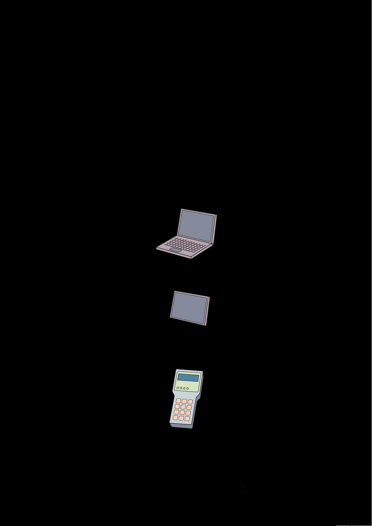
Compact
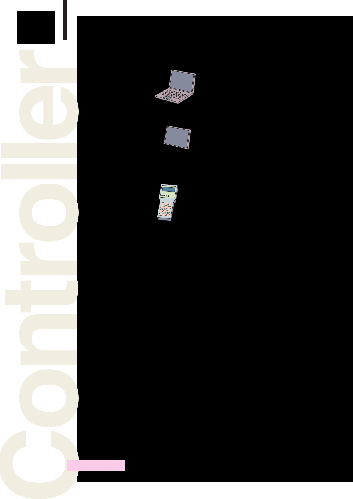
Controller
PC
USB connection
Reliability
Touch panel (to be developed)
[Recommended model : VT-2 (Keyence),
GOT-10 (Mitsubishi)]
Handy terminal (to be developed)
Driver
1 2
TBL-V Series motor
TBL-i ll Series motor

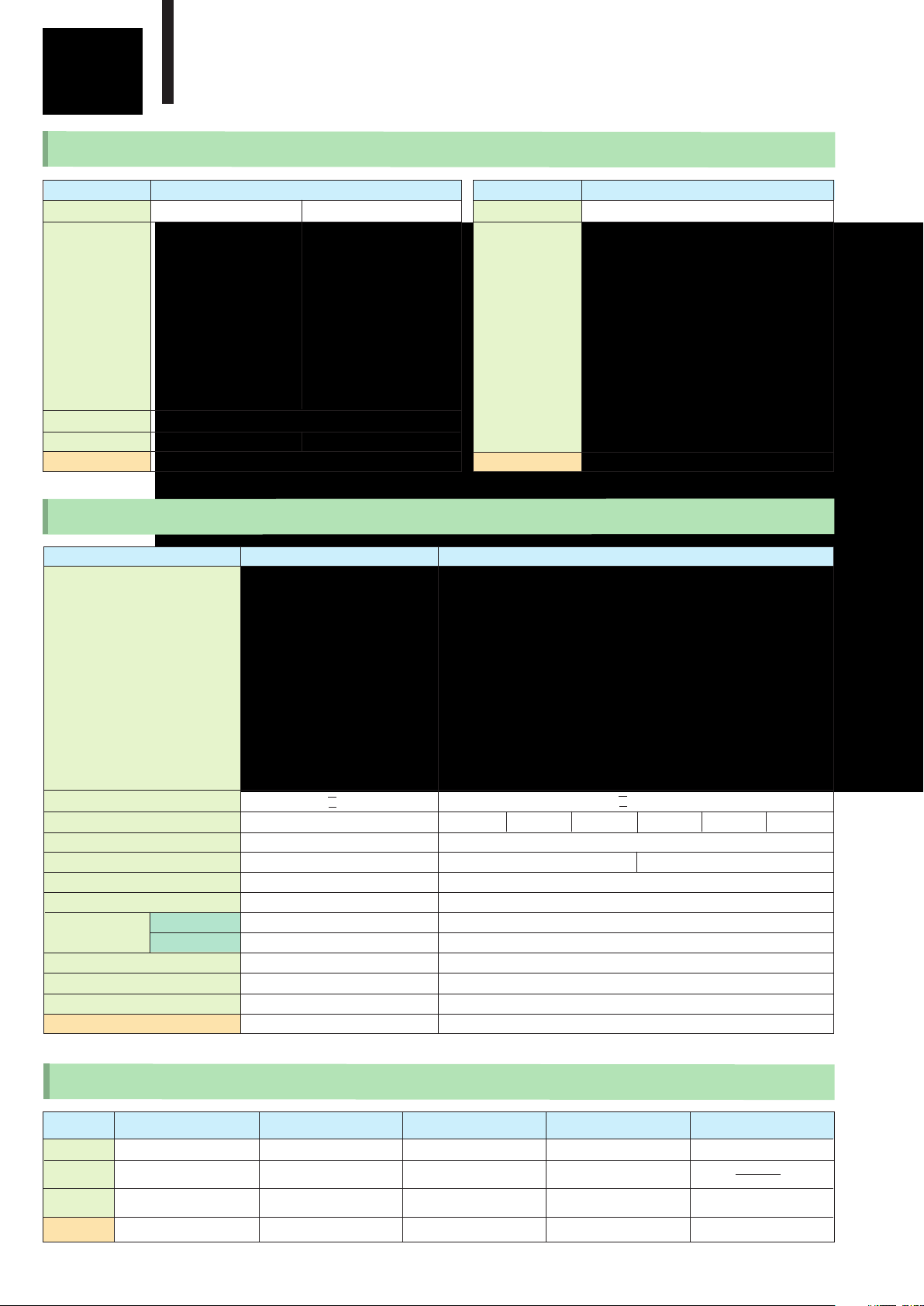
A novel proposition for compact network servos
Answers to your questions :
SV-NET motion controller network
Simple
Isn't your current system too large ?
・Compact system priced reasonably
・Compact size and volume
・Compact system of sequencer-less configuration
・Compact system offering a rich variety of commands
Isn't your motor prone to troubles ?
・A tough sensor nearly free from troubles
・Resolvers having proven its performance on vehicles, incorporated as the sensor
・Resolvers' MTBF being 1 million hours
Don't you want to reduce
the number of cables ?
・Network system designed to reduce amount of wiring
Compact
Reliability
Simple
Controller
Dedicated programming software
Offered free of charge : Free upgrading possible
"Control tower" for servo control
(Standard I/O 32/64)
RS-232C
Controller
PC
USB connection
Control power :
24VDC
Touch panel (to be developed)
[Recommended model :
VT-2 (Keyence),
GOT-10 (Mitsubishi)]
SV Programmer
Driver
Driver
Driver
Driver
Handy terminal
(to be developed)
motor
● 8-axis synchronous control
● S-curve / trapezoidal acceleration
and deceleration control
● Linear / circular interpolation
● Pass motions
● 8 user tasks
■ Applications
・Small to medium-size X-Y tables
・Belt conveyor units
・Handling units between equipments
・Automatic drilling and tapping machines
・Packing and packaging machines
・Food processing machines
・Automatic sorting machines
・Measuring and inspection systems
・Robots
・Textile and sewing machines
・AGV systems, automatic warehousing, etc.
Max. 8 axes connectable
3 4

Compact
Reliability
Simple
Motor
For the users who are planning "heavy-duty applications" for AC servo motors
● Heavy-load applications
● Z-axis applications
● IP 65 demanding applications
High-accuracy resolver mounted.
A rich lineup with options of speed reducer, brake, etc.
■ Applications
・Multiaxis robots
・Physical distribution machinery
・Food and packaging machinery
・Measuring equipment and the like
・Training equipment, medical and healthcare equipment
Optimal for speed control of equipment with simple positioning
and large load torque variation
For users who desire faster motion than with stepping motors
● Light-load applications
● Flanges of the same size as stepping motors
VR resolver mounted
■ Applications
・Weaving machines, embroidering machines
・Conveyance equipment, packaging equipment
・Uniaxial actuators
・Pumping equipment
・XY table / bench machine tools, etc.
Optimal for simple positioning and speed control applications
Compact
Reliability
Simple
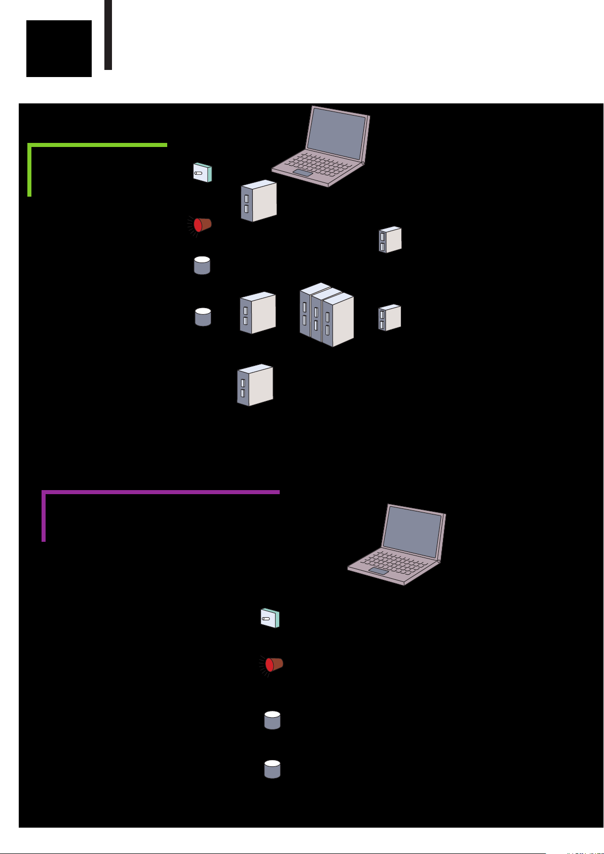
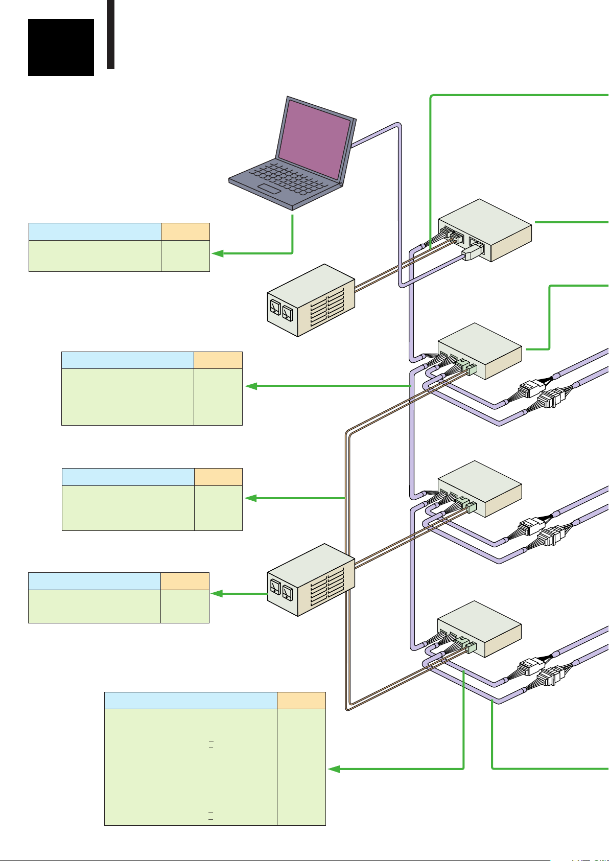
Servo System Configuration
Conventional
System
Conventional motion control
systems centered around PLC/
sequencers require a large
number of units.
Thus the users have to
take the trouble of learning about
their functions and operations.
Switch
Indicator lamp
Sensor
Sensor
Network Servo System
PC
■SV-NET is open for flexibility
I/O
I/O
Sequencer / PLC
Positioning unit
Positioning
unit
Driver
Driver
Motor
Motor
Communication
■SV-NET reduces components
SV-NET
Servo System Configuration
The SV-NET servo system employs a
controller with standard I/O interfaces and
network commands. With high-performance
drivers and rich motor variation, you can
structure a simple yet highly functional
motion control system. The SV-NET
not only provides optimal performance and
function to small to medium-size
systems but also helps reduce overall
cost reduction.
Indicator lamp
I/O
Switch
■SV-NET also works under RS-232C
PC
Driver
Motor
Driver
Sensor
Sensor
5 6
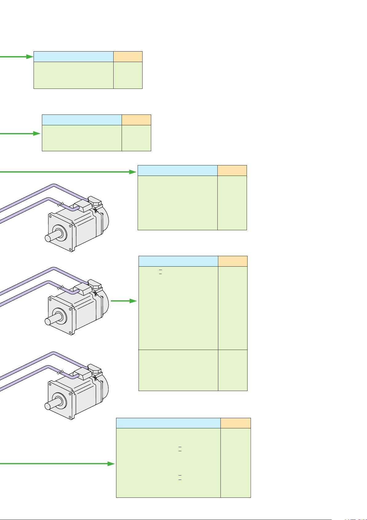
SV-NET controller
●SV-NET Servo System
Motor
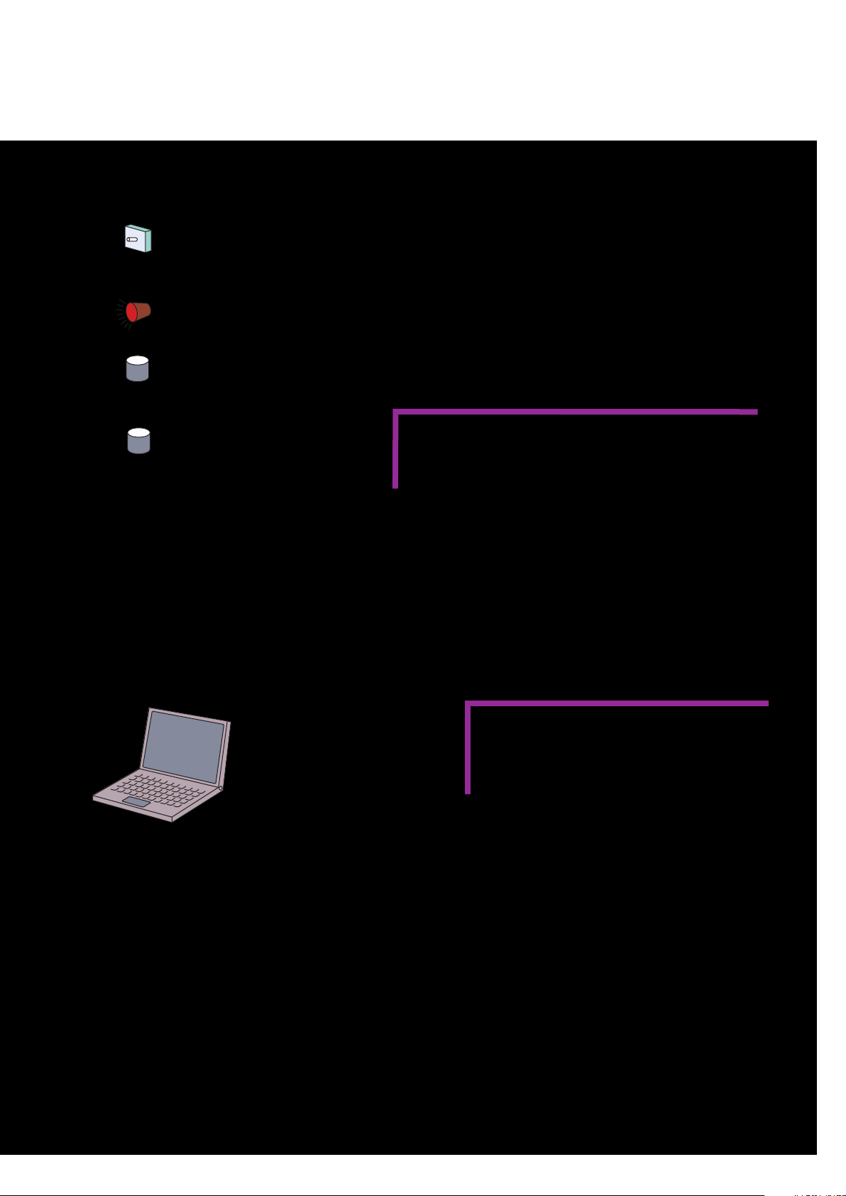
User's Own Controller
Switch
Indicator lamp
Sensor
Sensor
● SV-NET Servo System
Driver
Driver
Motor
Motor
SV-NET is open to customized
system configuration
For users thinking of using his own host controller
SV-NET, using a CAN in the physical layer, provides a
network featuring excellent general-purpose properties.
Any customer who already has a host controller for
CAN or is now developing one can use this system quite easily.
Note : Communication specifications are disclosed under a separate agreement.
PC
Communication unit or
Regenerative communication unit
●SV-NET Servo System
Driver
Driver
Motor
Motor
Simple motion control by
RS232C communication
In applications where high speed and complex
motions are not primary requirements and
multiaxial synchronous control is not necessary,
SV-NET drivers can be controlled via RS232C
serial data communication.
PC application software "Master of SV-NET ll"
helps you to check and simulate simple motions,
and to manage system and motion parameters.
Note : Communication specifications are disclosed under a
separate agreement.
Compact
Reliability
Simple
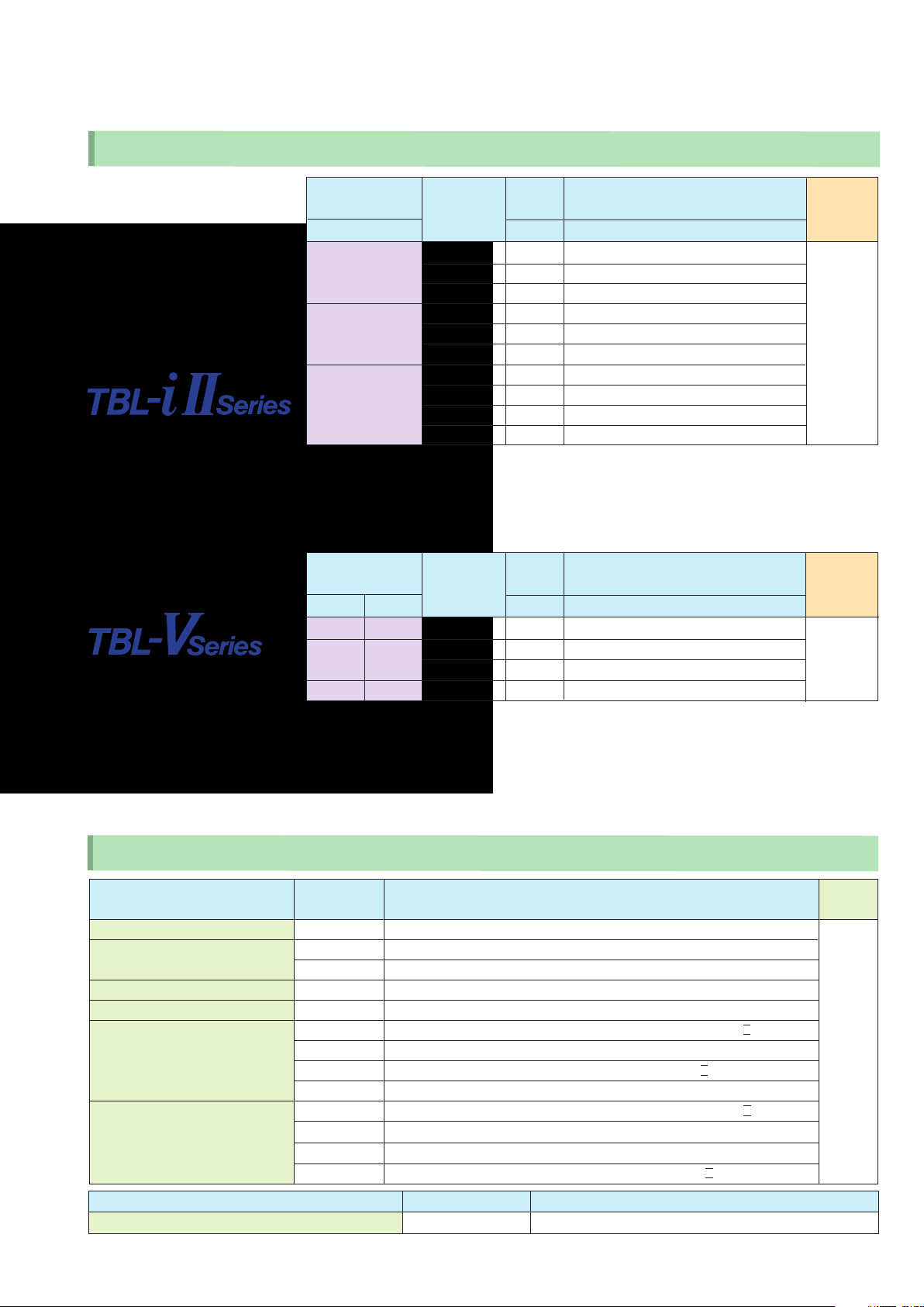
Product Lineup
SV-NET Controller
Model
Appearance
Supply voltage
I/O points
Page
SVCC- I SVCC-II
DC24V
32 64
SV-NET Driver
TA8440 series
11〜12
Model
Appearance
Page
SV Programmer
Programming software
Free of charge (Download from our website)
13〜14
Appearance
Combination motor series
Combination motor output
Control power source
Drive power source
Communication specifications
External connection I/O
Angle sensor
Regenerative capability
Dynamic brake
Mechanical brake output
Resolver
Encoder
Page
TA8410 series
TBL- i I I / TBL-V TBL- i lI / TBL-V
〜200W 〜100W 〜200W 〜400W 〜200W 〜400W 〜750W
DC24V DC24V
DC24V/48V AC100V AC200V
SV- N ET SV-N ET
○ ○
○ ○
○ ○
× ○
× ○
○ ○
15〜18
TA8411 series
19〜22
SV-NET Related Products
Regenerative
communication unit
Model
Related
equipment
Function
Page
7 8
TA8413
TA8410 series
Regen. com. function for
DC24V/DC48V units
25
Communication unit
TA8433
All SV-NET drivers
SV-NET com. Function
25
Master of SV-NET III
Software
All SV-NET drivers
Programming tool
26
Power supply unit
TA8 430
TA8420 series
DC288V 4-axis power +
Regen. Function
SV-NET training pack
TA8425
Controller + 3 sets of
motors & drivers
2623
AC Servo Motor
SV-NET Servo System
Mounting flange
[mm] [W] [V]
□40 TS4602 50
□60 TS4607 200
□80
Mounting flange
[inch] [mm] [W] [V]
#17 42 TS4742 50 DC24, DC48, AC100, AC200
TS4746 100 (DC24), DC48, AC100, AC200
#23 56.4
TS4747 200 (DC24), DC48, AC100, AC200
#34 86 TS4752 400 (AC100), AC200
Model
TS4601 30
TS4603 100
TS4606 100
TS4609 400
TS4611 200
TS4612 400
TS4613 600
TS4614 750
Model
Output
Output
Driver supply voltage
DC24, DC48, AC100, AC200
DC24, DC48, AC100, AC200
DC24, DC48, AC100, AC200
DC24, DC48, AC100, AC200
(DC24), DC48, AC100, AC200
AC100, AC200
AC100,AC200
AC200
AC200
AC200
Driver supply voltage
Page
27〜34
Page
35〜36
Cables & Accessories
Product type
Controller power cable
SV-NET cable
Driver power cable
Serial communication cable
Motor cable
Sensor cable
Product type
SV-NET terminating resistor unit
※Cable length can be specified by "N-number" in 10cm unit. (except for EU6517 : in 1m unit)
Model
EU9611
EU9610
EU9636
EU9613
EU6517
EU9614
EU9621
EU9635
EU9638
EU9615
EU9622
EU9645
EU9646
Related equipment
TA8440
TA8440 / TA8410 / TA8411 / TA8413 / TA8433
TA8420
TA8410 / TA8411 / TA8420 / TA8413
TA8440 (for upgrading firmware), TA8413 / TA8433
Combination of TA8410 / TA8420 and motor TBL-i ll series
Combination of TA8410 / TA8420 and motor TBL-i Vseries
Combination of TA8411and motor TBL-i ll series
Combination of TA8411and motor TBL-i V series
Combination of TA8410 / TA8411 and motor TBL-i ll series
Combination of TA8410 / TA8411 and motor TBL-i V series
Combination of TA8420 and motor TBL-i V series
Combination of TA8420 and motor TBL-i ll series
Model
EU9637
Page
37〜38
Related equipment
For TA8420
Compact
Reliability
Programming software
PC application software
"SV Programmer"
Simple
Product Categories
PC
Page
13〜14
Control power supply
Controller
Servo driver
Cable
SV-NET cable
TA8410/TA8 411/TA8413
/TA8433→EU 9610
TA8420→EU9636
Cable
Driver power cable
TA8410/TA8411/TA 8420
TA8413→EU9613
Power Supply
DC280V power supply
TA8430
Page
37
Servo driver
Page
37
Page
Servo driver
23
Drive power supply
Cable
Sensor Cable
TA8410/TA 8411
→EU9615 (for TBL- i I I connection)
TA8410/TA8411
→EU9622 (for TBL-V connection)
TA8420
→EU9645 (for TBL-V connection)
TA8420
→EU9646 (for TBL-iI I connection)
9
Page
38
SV-NET Servo System
Cable
Controller power cable
TA8440 series
→EU9611
Controller
SV-NET controller
TA8440 series
SVCC-I/SVCC-II
Page
37
Page
11〜12
Servo driver
SV-NET driver
DC24/48V 〜200W
TA 8 410 series
AC100/200V 〜750W
TA8411 series
DC280〜320V 750/400W
TA8420 series
Page
15〜24
Motor
Motor
Motor
Cable
AC servo motor
TBL-i II series
□40 30W TS4601
□40 50W TS4602
□40 100W TS4603
□60 100W TS4606
□60 200W TS4607
□60 400W TS4609
□80 200W TS4611
□80 400W TS4612
□80 600W TS4613
□80 750W TS4614
TBL-V series
#17 50W TS4742
#23 100W TS4746
#23 200W TS4747
#34 400W TS4752
Page
27〜34
35〜36
Page
Motor Cable
TA8410/TA8420
→EU9614 (for TBL-i II connection)
TA8410/TA8420
→EU9621 (for TBL-V connection)
TA8411
→EU9635 (for TBL-i II connection)
TA8411
→EU9638 (for TBL-V connection)
38
10
Compact
Reliability
Simple
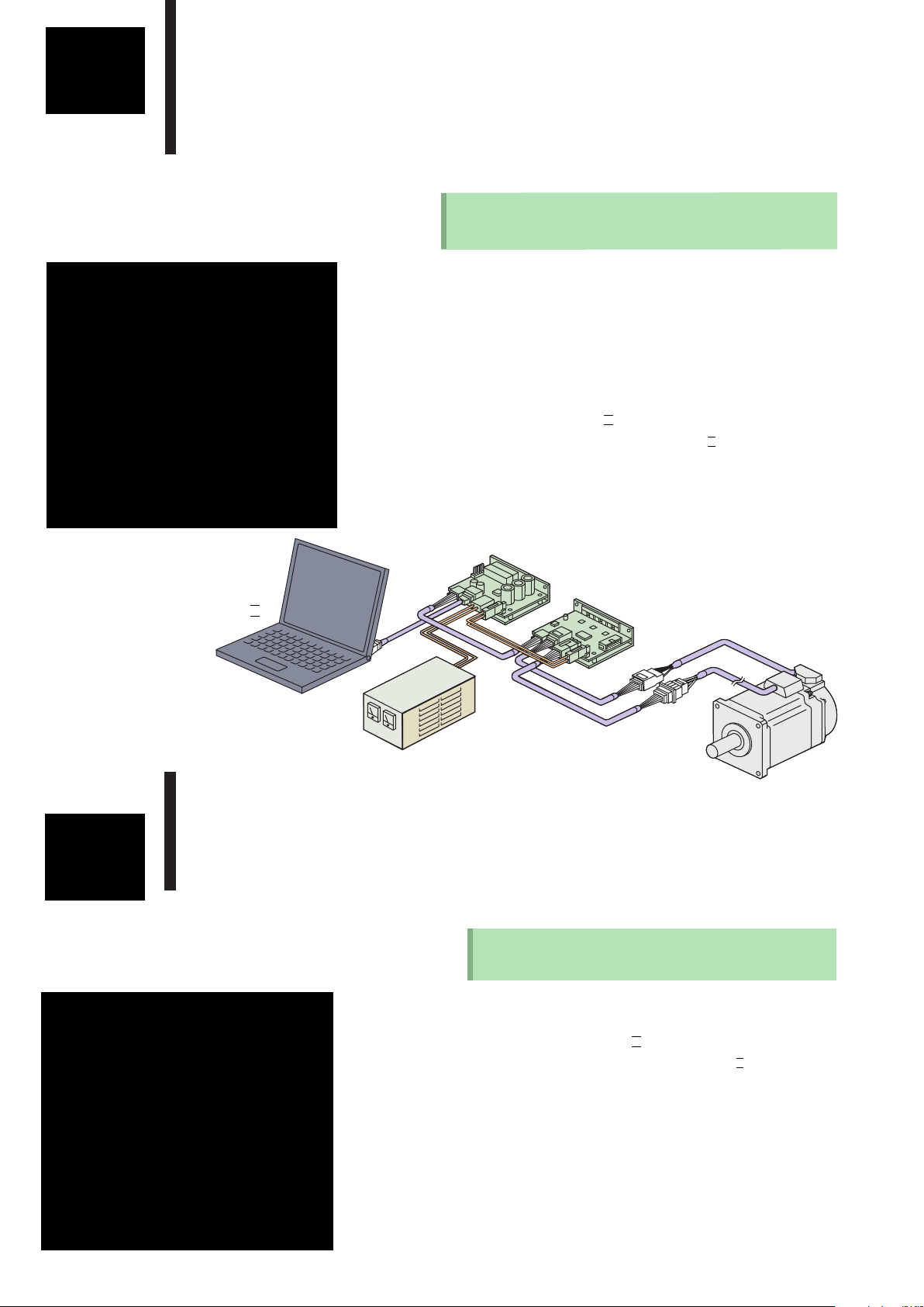
SV-NET Controller TA8440
SV-NET Controller "TA8440" and PC Software
"SV Programmer" being the
Mainstay of your Motion Control System
USB
Easy USB connection to PC.
Control power (DC24V)
Control power is supplied from the controller to all
the drivers via SV-NET cables.
Max. 8-axis control
Up to 8 axes controllable. Also synchronous operation
for 8 axes. Linear interpolation (8 axes),
circular interpolation (2 axes)
Stand-alone operation
The system can operate on a prepared program
without connecting PC.
Flexible system structuring possible by various I/O
combinations.
I/O interfaces up to 64 points
16 input points/16 output points : Total 32 points (SVCC-I)
32 input points/32 output points : Total 64 points (SVCC-II)
Main functions of TA8440
■ SV-NET port ×1
■ USB port ×1
■ Power supply DC24V
■ I/O 32 or 64 points
■ Stand-alone operation
■ Max. connectable axes : 8
■ 8-axis synchronous operation
■ Program memory capacity 640 KB
■ Interpolation cycle 4 ms
■ Transmission cycle 2 ms
PC application
■ SV Programmer (programming software)
You can download the programming software from the following
website free of charge :
http : //sv-net.tamagawa-seiki.com
Accessories
■ USB cable (for PC connection)
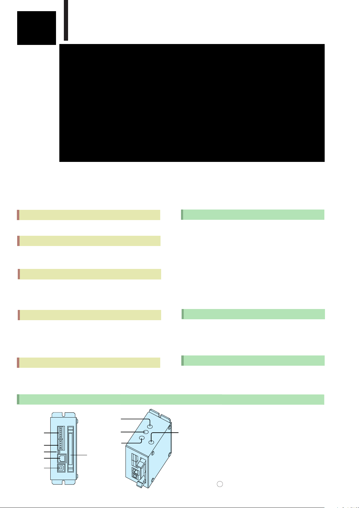
Names of TA8440 parts
1
SV-N ET : CAN Connector
○
7
SW-I D
○
8
HW-I D
○
○
9
BOOT
○
6
I/O
SV-N ET
1
○
2
Power
○
3
Status
○
4
RS232C
○
USB
5
○
11 12
10
○
PF No.
2
Power : Power input connector
○
3
Status : LED
○
4
RS232C : For upgrading firmware
○
5
USB : For PC connection
○
6
I/O : Connector
○
7
SW-ID : Set at factory
○
8
HW-ID : Set at factory
○
BOOT : Used for upgrading firmware
9
○
10
PF No. : Set at factory

SV-NET Servo System
TA8440 Model Designation
T A 8 4 4 0 N □ □ □ □ E □ □ □
Product type Cover color
10:SVCC-I
20:SVCC-II
0:Black (standard)
1:Black (standard)
2:Red
3:Silver
4:Green
5:Blue
6:White
Other option
0:Standard
TA8440 Basic Specifications
Unit specifications
■ Power input
DC24V±10%
Current consumption 0.3A Max.
■ SV-NET
Number of ports ×1
Communication protocol SV- NET
Physical layer:CAN
Control power output DC24V
■ USB
Number of ports ×1 for PC connection
■ I/O
1 port 32 points (16 input points, 16 output points)
SVCC - I ×1 port
SVCC- I I ×2 ports
■ Program memory capacity 640 KB
Motion control specifications
■ Number of control axes : 8
■ Transmission cycle : 4ms
Software
■ PC application
SV Programmer
Environmental specifications
■ Operation environment 0〜40℃ 90%RH Max.
No condensation
■ Storage temperature −10〜85℃
■ Applicable standard RoHS Directive
Accessories
■ USB cable (for PC connection)
■ SV Programmer
Installation CD for a charge is available.
Free download is available from web site.
http : //sv-net.tamagawa-seiki.com
Software specification
100:Standard
42
TA MAGAWA
SV-NET
POWER
116
108
100
RS232C
USB
STATU S
SVCC- I
PF-1
4.2
55
TA MAGAWA
SV-NET
POWER
116
108
100
RS232C
USB
STATU S
SVCC- II
PF-1
PF-2
4.2
SVCC - II
External Connection Diagram
USB
PC
SV-NET
Driver
Power
supply
SV-N ET
Power
1
GND
2
CAN_L
3
SHIELD
4
CAN_H
5
+24V
GND
1
NC
2
NC
3
+24V
4
Current
capacity
100 mA Max.
Current
capacity
100 mA Max.
Current
capacity
100 mA Max.
Current
capacity
100 mA Max.
×4
×4
×4
×4
×4
×4
×4
×4
SVCC - I
I/O -1 & I/O-2
1
2
3
4
5
6
7
8
9
10
11
12
13
14
15
16
17
18
19
20
21
22
23
24
25
26
27
28
29
30
31
32
33
34
35
36
37
38
39
40
73
73
Input power 24V IN 0-3
Input power 24V IN 4-7
IN 0
IN 1
IN 2
IN 3
IN 4
IN 5
IN 6
IN 7
Input power 24V IN 8-11
Input power 24V IN 12-15
IN 8
IN 9
IN 10
IN 11
IN 12
IN 13
IN 14
IN 15
Output power ground OUT 0-3
Output power ground OUT 4-7
OUT 0
OUT 1
OUT 2
OUT 3
OUT 4
OUT 5
OUT 6
OUT 7
Output power ground OUT 8-11
Output power ground OUT 12-15
OUT 8
OUT 9
OUT 10
OUT 11
OUT 12
OUT 13
OUT 14
OUT 15
2
2

Compact
Reliability
Simple
SV Programmer
Programming Servo monitor
Jog operation
Parameter
management
Up-to-date programming with a
rich supply of commands realizing
a speedy and flexible system development for you !
Programming tool "Program Grid"
Programming is done in Tamagawa's original
language.
That is, you select a command from the pull-down
menu in each step and enter an argument in
correspondence to the command.
The up-to-date programming is quite easy.
"Servo Monitor" for graphical view
of operation
Positions, speeds, and currents are logged and
displayed in graphs.
Axes of the graphs are scalable as you like.
"Jog Operation" for trial run
Constant speed operation or step operation can be
performed for each individual axis.
In JOG operation, you can operate the motor without
programming, just by selecting menu.
Main Functions of SV Programmer
■ Program Grid
Tamagawa's original language
Max. 5000 steps
Program memory capacity 640 KB
Variables capacity 32KB
■ Jog operation
Constant speed operation and step operation possible
Override function usable
■ Servo monitor function
Monitored items : Position, speed, and feedback current
Time axis and measurement axis scale changeable
■ Device setup
Device (driver) parameter management
Display in list or in category
Changing and saving parameters
Upload/Download, storage, printing, etc.
of parameter data
■ Controller setup
Parameter information management for SV-NET controller
Display in list or in category
Changing and saving parameters
Upload/Download, storage, printing, etc. of parameter data
13

"Device Setup" for collective parameter management
The parameters for the connected devices (drivers)
can be managed collectively.
The parameter settings can be loaded, stored, and
printed. The category display facilitates adjustments
with its easy-to-understand display of parameters
such as control modes, servo commands, and servo
gains.
Unique programming commands
■The user can customize the acceleration
/deceleration pattern, using composite commands.
In addition to movement patterns, such as
trapezoidal and S-curve patterns, you can create
your own acceleration / deceleration patterns
optimum for the system.
■Monitor commands for checking status of the
controller or drivers
set specified data in variables.
You can use these variables in the program to make
the motion so flexible.
■Use of indirect reference to variables enhances the
efficiency of programming.
You can accomplish a speedy system development.
SV-NET Servo System
Basic Specifications
■ PC environment
Applicable model PC/AT compatible machine
Applicable OS Windows 2000, XP, Vista
Necessary memory 256 MB Min.
Hard disk 500MB Min.
■ USB
USB 2.0 Full Speed
■ Programming specifications
Language Tamagawa's original language
Program capacity 640 KB
Program steps Max. 5000 steps
User tasks Max. 8 tasks
Variables capacity 32KB
Variables type 32-Bit signed integer
(−2147483648〜2147483647)
Arithmetic operation Substitution, unary, addition,
subtraction, multiplication,
division, remainder
Logical operation Logical inversion, logical
multiplication (AND), logical
addition (OR), exclusive OR,
logical shift
Jump instructions Unconditional jump, unary,
AND, equality sign,
inequality sign, less or equal,
more or equal, small, large
Subroutines Call instruction available
■ Motion control specifications
Number of control axes Max. 8
Transmission cycle 2ms
Interpolation cycle 4 ms
Interpolation function Linear interpolation ( 8axes)/
Circular interpolation (2axes)
Control system Position control, speed control,
current control
Compensation function Electronic gear
Command units mm /deg (in position control)
Acceleration/deceleration
S-curve and trapezoidal control
Home position return function
Jog operation
Override function
SV- N ET 1 system
14

Compact
Reliability
Simple
SV-NET Driver TA8410 Series
AC Servo Drivers running on 24V/48VDC and max. 200W
Powerful functions within a compact body !
SV-NET in daisy chain
Daisy chain connection minimizes wiring
requirement.
Powerful functions
The functions packed into the small framework
facilitate not only network connection, but also
easy external signal inputs such as pulse commands
or analog commands through the use of an I/O
connector.
The extension board built-in type SVD-DW has
add-on functions, which can interface with
A/B/Z outputs and encoder as well.
Resolver
The standard brushless resolver is employed as a
high-reliability angle sensor.
Compatible with a variety of encoders
The drivers interface not only with the
resolver but also with various encoders.
(SVD-DW with built-in extension board only)
Drive power DC24/48V
Main Functions of TA8410
■ Control commands
Position command input SV-NET/pulse command
Speed command input SV-NET/analog command
Current command input SV-NET/analog command
■ Parameter setting functions
Control mode, Position loop gain, Speed loop gain,
Speed integration gain,
Feed forward, Resonance control filter, Analog
command scale setting, Electronic gear setting,
Smoothing, Acceleration limit, etc.
■ Protective functions
Sensor error, Drive power error,
Over-heat, Over-speed, Overload,
Excessive deviation, etc.
■ Applicable sensors
Brushless resolver (Smartsyn/Singlsyn)
Encoder 17BIT- INC /ABS (SVD-DW only)
Encoder Minimal wiring incremental
(SVD - DW only)
■ Input and output signals
Servo ON input, Alarm reset input, Alarm output,
In-the-position output, A/B/Z output
(SVD-DW with built-in extension board only), etc.
Product & Accessories
■TA8 410 unit only
15 16

SV-NET Servo System
TA8410 Model Designation
TA8410 N □○○○ E □
Software specifications
100〜:See list of motor-driver combinations.
Sensor specifications
N1 * * * E5 * * : 2048 C/T
Minimal wiring incremental (*1)
N3 * * * E6 * * :17 B I T-A BS (*1)
N3 * * * E7 * * :17 B I T- I N C (*1)
N7 * * * E1 * * / E2 * * :Brushless resolver
I/O specifications, etc.
0:I/O I/F absent (standard, network connection only)
1:I/O I/F present (right angle type/with lock)
2:I/O I/F present (straight type/with lock) (*2)
3:I/O I/F present (right angle type/without lock)
4:Extension board (open collector output)+I/O I/F absent (*3)
5:Extension board (open collector output)
+ I/O I/F present (right angle/with lock) (*3)
6:Extension board (open collector output)
+ I/O I/F present (right angle/without lock) (*3)
7:Extension board (line driver output)+I/O I/F absent (*3)
8:Extension board (line driver output)
+ I/O I/F present (right angle/with lock) (*3)
9:Extension board (line driver output)
+ I/O I/F present (right angle/without lock) (*3)
(*2) Setting possible for open frame type only
(*3) SVD-DW type
Casing specifications, etc.
1:Covered type (BLACK:standard)
2: 〃 (RED)
3: 〃 (SILVER)
4: 〃 (GREEN)
5: 〃 (BLUE)
6: 〃 (WHITE)
※…… 0 as per separate product specifications
0:Open frame
Continuous rating output current specifications
3:4 Arms (12 Arms Max.)
5:8 Arms (24 Arms Max.)
Basic model
TA8410 (low-voltage drive) series
□
□
(Singlsyn/Smartsyn)
(*1) SVD-DW type
Basic Specifications
ltem TA 8 410 series
Control power voltage ※1
Drive power voltage ※1
Control power current
Drive power capacity
Communication specifications
Sensor
Driver internal resolution
Brushless resolver
(Singlsyn/Smartsyn)
2048 (1/rev) 2 (1/rev) 2048 (1/rev)
Combination motors
Combination motor output [W]
Operating temperature range
Storage temperature range
Operating humidity
Definition of rotating direction
CW rotation as viewed from motor shaft end : Forward rotation ※2
Recommended load inertia
Mass
Directive
※1…Do not use the same power supply for the control power and the drive power
(when the drive power is DC24V). Otherwise, troubles may occur. When
the use of the same power supply is inevitable, take precautions, such as
inser ting a diode, so that the voltage variation on the drive power side may
not adversely affect the control power side.
※2…Definition of rotating direction can be changed by parameter.
DC24V ±10%
DC24〜48V ±10%
0.1 A
As per motor combination
Communication protocol:SV-NET
Physical layer:CAN
17BIT-ABS/
17BIT- INC
17
TBL-V series / TBL- i I I series
〜200W
0〜+40℃
−10〜+85℃
90%RH Max. (no condensation)
30 times the motor inertia Max.
Approx. 0.3kg
Complying with RoHS Directive
Min.wiring
incremental encoder
Control Specifications
Control specifications As per separate communication specifications
Baud 1 Mbps
rate
MAC I D 31
(factory set value : changeable by parameter)
(factory set value : changeable by rotary SW or by parameter)
External View & Dimensions
SVD-DL
(2)
4
±0.5
108
30
15
±0.2
4.5
TA MAGAWA
STATUS
CN2
SV-NET
CN5
SENSOR
CN3
MOTOR
CN1
POWER
SVD-DL
4.5
±0.5
116
±0.2
Resolver type
(8)
(CONTROL/CAN)
100
(8)
CN2
CN5
(SENSOR)
CN3
(MOTOR)
CN1
(POWER)
(15)
LED
(STATUS)
MAC ID
SVD-DW
17.5
CN9
BAT
CN10
MON
M4 setscrew hole
(2)
4
CN9
(BATTERY)
±0.5
±0.5
108
116
CN10
(MONITOR)
(8)
LED
(STATUS)
CN2
(CONTROL/SV-NET)
CN5
(SENSOR)
100
CN3
(MOTOR)
CN1
(POWER)
CN8
(I/O 2)
CN7
(I/O 1)
(15)
CN8
(I/O 2)
CN7
(I/O 1)
75
(3)
MAC ID
75
(3)
35
±0.2
4.5
TA MAGAWA
STATUS
CN2
SV-NET
CN5
SENSOR
CN3
MOTOR
CN1
POWER
SVD-DW
Built-in extension board type
Resolver type
Encoder 17Bit ABS/INC
Encoder 2048C/T INC

Compact
Reliability
Simple
Connection
CN1 (main power)
Connector for supplying main power (drive power).
●Header:5569-02A1 (MOLEX)
PIN No. FUNCTION
1 GND(main)
2 DC24V/DC48V(main)
Mating connector (not supplied as accessory)
・Receptacle housing:5557-02R (MOLEX)
・Terminal :5556-TL (MOLEX)
CN3 (motor connection)
Connector for connecting motor cable
●Header:5569-06A1 (MOLEX)
PIN No.
1
2
3
4
5
6
Mating connector (not supplied as accessory)
・Receptacle housing:5557-06R (MOLEX)
・Terminal :5556-TL (MOLEX)
(BK)……motors with brake only
(BK)……motors with brake only
FUNCTION
Standard
U
V
W
F・G
CN7 (I/O connection)
Connectors for connecting I/O input/output signals.
Connector types vary depending on "N-number."
●N***1 header:HIF3BA-16PA-2.54DS (HIROSE)…right angle, with lock
●N***2 header:HIF3BA-16PA-2.54DSA (HIROSE)…straight, with lock
●N***3 header:HIF3F-16PA-2.54DS (HIROSE)…right angle, without lock
PIN No.
※「A-I n」:Analog signal input,「D-I n」:Signal input,「D-O ut」:Digital signal output
1
○
MCP604 equivalent TLP112A equivalent
10kΩ
※Mating connector (to be prepared by users)
・Socket:HIF3BA-16D-2.54R (HIROSE)
I/O FUNCTION
GND
1
A-In AIN (Analog command input) See Fig. 1
2
D-In Reverse-PLS+ (Reverse command pulse input+)
3
D-In Reverse-PLSー (Reverse command pulse input−)
4
D-In Forward-PLS+ (Forward command pulse input+)
5
D-In Forward-PLSー (Forward command pulse input−)
6
GND
7
D-In AUX (Auxiliary)
8
D-In C-RST (Counter reset input)
9
D-In RST (Reset input) See Fig. 3
10
D-In Reverse-LMT (Reverse drive disable input)
11
D-In Forward-LMT (Forward drive disable input)
12
D-In SVON (Servo ON input)
13
D-In INP (In-the-position signal output)
14
D-Out ALM (Alarm signal output)
15
+24V
16
Analog signal input
1.65kΩ
Vref(+1.65V)
Digital signal input
2
○
150Ω
I/O internal circuit
Digital signal input
3
○
1SS388 equivalent
+5V
470Ω
74VHC04
ON:1V Max.
OFF:open or 3.5V Min.
(Reverse voltage of diode : 40V)
4
○
SSM5N15FE equivalent
15
16
CN7 Pin number
17 18
2
1
CN1 Pin number
5
6
4
3
2
1
CN3 Pin number
See Fig. 2
See Fig. 4
Digital signal output
DG
3
1
4
2
CN2 (control signal)
Connector for connecting control power (DC24V) and communication
(CAN). Even when communication (CAN) is not used, be sure to input
control power (DC24V) between PIN 1 and PIN 5 of the CN2.
●Header:734-165 (WAGO)
PIN No. FUNCTION
1 GND (control)
2 CAN L (ー)
3 GND (SHIELD)
4 CAN H (+)
5 DC24V (control)
Mating connector (not supplied as accessory)
・Connector plug:734-105 (WAGO)
CN5 (sensor connection)
Connector for connecting sensor cable
●Tab header:1376020-1 (Tyco Electronics AMP)
PIN No.
A1
B1
A2
B2
A3
B3
A4
B4
A5
B5
A6
B6
Mating connector (not supplied as accessory)
・Receptacle housing:1-1318118-6 (Tyco Electronics AMP)
・Terminal :1318108-1 (Tyco Electronics AMP)
Min. wiring 17BIT-ABS/INC Resolver
A − S2 (output)
A/ − S4 (output)
B − S1 (output)
B/ − S3 (output)
Z SD R1 (excitation)
Z/ SD/ R2 (excitation)
− VB −
− GND-VB −
VCC VCC −
GND GND ー
− − ー
GND (SHIELD) GND (SHIELD) GND (SHIELD)
FUNCTION
CN8 (I/O connection) SVD-DW only
●Header:HIF3BAF-14PA-2.54DS (HIROSE)
PIN No.
1
2
3
4
5
6
7
8
9
10
11
12
13
14
※「D-Out」:Digital signal output,
CN9 (
※Used with 17B-ABS encoder only
●Connector:IL-2P-S3FP2-1 (JAE)
Battery:ER17500VC (Toshiba Battery)
I/O
D-Out
D-Out NC LEAD ー
D-Out LAG LAG +
D-Out NC LAG ー
D-Out Z Z+
D-Out NC Zー
GND
GND
A-Out Monitor output1
(factory setting:motor current)
A-Out Monitor output2
(factory setting:speed feedback)
Open cnnector Line driver
LEAD LEAD +
「A-Out」:Analog signal output
FUNCTION
GND
GND
NC
NC
backup battery connection connector) SVD-DW only
PIN No. FUNCTION
1 GND (ー)
2 VB (+)
1
5
CN2 Pin number
1
CN9 Pin number
2

List of Motor / Driver Combinations
SV-NET Servo System
●TBL-V Series (E1 )
□
□
DC24V system / DC48V system
Motor model
Driver model to be combined
TS4742 (50W/50W-□42) TA8410N*5**E111
TS4746 (98W/100W-□56.4) TA8410N*5**E112
TS4747 (92W/200W-□56.4) TA8410N*5**E113
Note) TBL- V series employs the resolver (Singlsyn) only.
Compact
Reliability
Simple
System Configuration
DC24/48 Type
TBL-V/TBL-i II MOTOR
TBL-V/TBL-i II MOTOR
TBL-V/TBL-i II MOTOR
TA8410 TBL-DRIVER
SENSOR
MOTOR
TA8410 TBL-DRIVER
SENSOR
MOTOR
TA8410 TBL- DRIVER
SENSOR
MOTOR
CN4
CN3
CN4
CN3
CN6
CN2
CN2
CN1
CN2
CN1
CN2
CN1
CAN+
4
CANー
2
GND
3
GND
1
DC24V
5
GND
1
DC24/48V
2
CAN+
4
CANー
2
GND
3
GND
1
DC24V
5
GND
1
DC24/48V
2
CAN+
4
CANー
2
GND
3
GND
1
DC24V
5
GND
1
DC24/48V
2
Twist Pair /
Each Pair Shielded +
All Shielded Cable
Twist Pair /
Each Pair Shielded +
All Shielded Cable
Twist Pair /
Each Pair Shielded +
All Shielded Cable
●TBL- i II Series (E2 )
DC24V system
Motor model
□
□
Driver model to be combined
DC48V system
Motor model
Driver model to be combined
TS4601 (30W-□40) TA8410N*3**E241 TS4601 (30W-□40) TA8410N*3**E281
TS4602 (50W-□40) TA8410N*3**E242 TS4602 (50W-□40) TA8410N*3**E282
TS4603 (100W-□40) TA8410N*5**E243 TS4603 (100W-□40) TA8410N*3**E283
TS4606 (100W-□60) TA8410N*5**E256 TS4606 (100W-□60) TA8410N*3**E296
TS4607 (100W-□60) TA8410N*5**E257 TS4607 (200W-□60) TA8410N*5**E297
SV-N ET Motion Controller
(Termination resistor)
(120Ω)
PC
CAN+
4
CANー
2
3
GND
1
GND
(Built-in
5
DC24V
termination
1
4
resistor)
GND
(120Ω)
USB
DC24V
Control Power Supply:DC24V
GND
DC24V
Drive power:DC24〜48V
0V
DC24〜48V
PC
SV-N E T Controller
Terminating resistor 120Ω to be connected
Control Power
DC24V
Drive Power Supply
DC24/48V
SV-N ET Driver TA 8410
Motor
SV-N E T Driver TA 8410
Motor
SV-N ET Driver TA8 410
Motor

Compact
Reliability
Simple
SV-NET Driver TA8411 Series
AC Servo Drivers running on
100V/200VAC outputs up to
750W within a compact body.
SV-NET in daisy chain
The daisy chain connection minimizes wiring
requirement.
TA8411 Model Designation
TA8411 N □○○○ E □
Software specifications
100〜:Standard specifications
Sensor specifications
N1 * * * E5 * * :2048 C/T
Minimal wiring incremental
N3 * * * E6 * * :17 BIT-ABS
N3 * * * E7 * * :17 BIT- INC
N7 * * * E1 * * / E2 * * :Brushless resolver
Mechanical specifications, etc.
1:Extension board (open collector output)
2:Extension board (I ine driver output)
Casing specifications, etc.
1:Covered type (BLACK:standard)
2: 〃 (RED)
3: 〃 (SILVER)
4: 〃 (GREEN)
5: 〃 (BLUE)
6: 〃 (WHITE)
Input voltage / output current specifications
2:AC100V / 2 Arms (6 Arms Max.)
3:AC100V / 4 Arms (8 Arms Max.)
4:AC100V / 6 Arms (12 Arms Max.)
6:AC200V / 2 Arms (6 Arms Max.)
7:AC200V / 4 Arms (8 Arms Max.)
8:AC200V / 6 Arms (12 Arms Max.)
Basic model
TA8411 (high-voltage drive) series
□
□
(Singlsyn/Smartsyn)
Powerful functions
The functions packed into the small framework
facilitate not only network connection, but also
easy external signal inputs such as pulse commands
or analog commands through the use of an I/O
connector. It outputs A/B/Z signals and interfaces
with encoders as well.
Resolver
Brushless resolver is used as the standard
high-reliability angle sensor.
Compatible with a variety of encoders
The drivers are compatible not only with the
resolver but also with various encoders.
Drive power AC100/200V
Single-phase, AC90~115V/AC180~253V, 50Hz/60Hz
Dynamic brake and regenerative circuit
are built
Product & Accessories
■TA8411 unit only
Main Functions of TA8411
■ Control commands
Position command input SV-NET/pulse command
Speed command input SV-NET/analog command
Current command input SV-NET/analog command
■ Parameter setting functions
Control mode, Position loop gain, Speed loop gain,
Speed integration gain,
Feed forward, Resonance control filter, Analog
command scale setting, Electronic gear setting,
Encoder output resolution setting, Acceleration limit, etc.
■ Regenerative function Built-in circuit
■ Dynamic brake function Built-in circuit
■ Mechanical brake drive output DC24V-0.4A Max.
■ Protective functions
Sensor error, Drive power error,
Over-heat, EEPROM error, Over-speed
Overload, Excessive deviation, etc.
■ Applicable sensors
Brushless resolver (Smartsyn/Singlsyn)
Encoder 17BIT- INC /ABS
Encoder Minimal wiring incremental
■ Input and output signals
Servo ON input, Alarm reset input, Alarm output,
In-the-position output, A/B/Z output
(built-in extension board type only), etc.
19 20

Basic Specifications
ltem TA 8 411 series
Control power voltage
Drive power voltage
Control power current
Single-phase, AC90〜115V / AC180〜253V 50/60 Hz
0.1 A (fan type:+0.1A / brake type:+0.4A)
Drive power capacity
Communication specifications
Sensor
Driver internal resolution
Brushless resolver
(Singlsyn/Smartsyn)
2048 (1/rev) 2 (1/rev) 2048 (1/rev)
Combination motor
Combination motor output [W]
Operating temperature range
Storage temperature range
Operating humidity
Definition of rotating direction
CW rotation as viewed from motor shaft end : Forward rotation
Recommended load inertia
Mass
Directive
DC24V ±10%
As per motor combination
Communication protocol:SV-NET
Physical layer:CAN
17BIT-ABS/
17BIT-INC
17
Min. wiring
incremental encoder
TBL-V series / TBL- i I I series
〜400W (drive power AC100V)
〜750W (drive power AC200V)
0〜+40℃
ー10〜+85℃
90%RH Max. (no condensation)
30 times the motor inertia Max.
Approx. 0.6kg
Complying with RoHS Directive
Control Specifications
Control specifications As per separate communication specifications
Baud rate 1 M bps
MAC I D 31
(factory set value : changeable by parameter)
(factory set value : changeable by rotary SW or by parameter)
SV-NET Servo System
External View & Dimensions
SVD-ALW
15
φ5
TA MAGAWA
CN7
I/O 1
CN2
SV−
NET
POWER
37
5
*
STATUS
SVD-ALM
±1
STATUS
(LED)
CN2
(CONTROL/
SV-NET)
POWER
(LED)
FG
(M 4 screw)
TA8411 N 2 / N 6
CN9
BAT
CN8
I/O 2
CN10
MON
CN5
SENSOR
CN3
MOTOR
CN1
POWER
15
*
CN9
(BATTERY)
CN10
(MO NITO R)
CN1
(AC I N)
R2.5
*
* *
160
10
±0.5
*
170
5
±1
180
CN6
(DB/RB)
CN6
DB/RB
(Mounting surface)
±1
130
(3)
External View & Dimensions
SVD-AMW
15
φ5
TA MAGAWA
CN7
I/O 1
CN2
SV−
NET
POWER
37
SVD-AMW
5
±1
*
STATUS
STATUS
(LED)
CN2
(CONTROL/SV-NET)
POWER
(LED)
FG
(M 4 screw)
TA8411 N 3 / N 7
*
CN9
BAT
CN8
I/O 2
CN10
MON
CN5
SENSOR
CN3
MOTOR
CN1
POWER
15
*
CN9
(BATTERY)
CN10
M ON ITO R
CN1
(AC I N)
R2.5
(3)
* *
160
10
*
±0.5
170
5
±1
180
CN6
(DB/RB)
CN6
DB/RB
130
(Mounting surface)
±1
(3)
SVD-AHW
φ5
25
TA MAGAWA
CN7
I/O 1
CN2
SV−
NET
POWER
5
47
STATUS
SVD-AHW
±1
*
CN9
BAT
CN8
I/O 2
CN10
MON
CN5
SENSOR
CN3
MOTOR
CN1
POWER
25
*
* *
(BATTERY)
M ON ITO R
STATUS
(LED)
CN2
(CONTROL/SV-NET)
POWER
(LED)
CN1
(AC I N)
FG
(M 4 screw)
TA8411 N 3 / N 7
CN9
CN10
R2.5
(3)
(Mounting surface)
±1
±0.5
160
180
170
±1
CN6
(DB/RB)
CN6
DB/RB
130
5
10
*
*
(3)

Compact
Reliability
Simple
Connection
CN1 (main power)
Connector for supplying main power (drive power).
●Header:5569-02A1 (MOLEX)
PIN No. FUNCTION
1
2
Mating connector (not supplied as accessory)
・Receptacle housing:5557-02R (MOLEX)
・Terminal :5556-TL (MOLEX)
Single-phase AC100V / AC200〜220V (main)
CN3 (motor connection)
Connector for connecting motor cable
●Header:1-178139-2 (Tyco Electronics AMP)
PIN No.
A1
A2
A3
B1
B2
B3
Mating connector (not supplied as accessory)
・Receptacle housing :1-178129-6
・Receptacle contact :175218-2
(BK)……Motors with brake only
(BK)……Motors with brake only
(Tyco Electronics AMP)
(Tyco Electronics AMP)
FUNCTION
Standard
U
V
W
F・G
CN6 (External resistance)
Connectors for connecting external resistance.
●Header:5569-04A1 (MOLEX)
PIN No. FUNCTION
1
2
3
4
Mating connector (not supplied as accessory)
・Receptacle housing:5557-04R (MOLEX)
・Terminal :5556TL (MOLEX)
RG1 (regenerative resistance connection)
DB1 (dynamic brake resistance connection)
RG2 (regenerative resistance connection)
DB2 (dynamic brake resistance connection)
CN7 (I/O connection)
Connectors for connecting I/O input/output signals.
●Header:HIF3BAF-16PA-2.54DS (HIROSE)
PIN No.
※「A-In」:Analog signal,「D-In」:Signal input,「D-Out」:Digital signal output
I/O FUNCTION
GND
1
A-In AIN (Anglog command input) See Fig. 1
2
D-In Reverse-PLS+
3
D-In Reverse-PLSー
4
D-In Forward-PLS+
5
D-In Forward-PLSー
6
GND
7
D-In AUX (Auxiliary input)
8
D-In C-RST (Counter reset input)
9
D-In RST (Reset input) See Fig. 3
10
D-In Reverse-LMT (Reverse drive disable input)
11
D-In Forward-LMT (Forward drive disable input)
12
D-In SVON (Servo ON input)
13
D-In INP (In-the-position signal output)
14
D-Out ALM (Alarm signal output)
15
+24V
16
(Reverse command pulse input+)
(Reverse command pulse input−)
(Forward command pulse input+)
(Forward command pulse input−)
CN1 Pin number
A1
CN3 Pin number
CN6 Pin number
See Fig. 2
See Fig. 4
2
1
B1
B2
B3
A2
A3
4
3
2
1
CN2 (control signal)
Connector for connecting control power (DC24V) and communication
(CAN). Even when communication (CAN) is not used, be sure to input
control power (DC24V) between PIN 1 and PIN 5 of the CN2.
●Header:734-165 (WAGO)
PIN No. FUNCTION
1 GND (control)
2 CAN L (ー)
3 GND (SHIELD)
4 CAN H (+)
5 DC24V (control)
Mating connector (not supplied as accessory)
・Connector plug:734-105 (WAGO)
CN5 (sensor connection)
Connector for connecting sensor cable
●Tab header:1376020-1 (Tyco Electronics AMP)
PIN No.
A1
B1
A2
B2
A3
B3
A4
B4
A5
B5
A6
B6
Mating connector (not supplied as accessory)
・Receptacle housing:1-1318118-6 (Tyco Electronics AMP)
・Terminal :1318108-1 (Tyco Electronics AMP)
Analog signal input
1
○
MCP604 equivalent
1.65kΩ
10kΩ
Vref (+1.65V)
※Mating connector (not supplied as accessory)
・Socket:HIF3BA-16D-2.54R (HIROSE)
Min. wiring 17BIT-ABS/INC Resolver
A − S2 (output)
A/ − S4 (output)
B − S1 (output)
B/ − S3 (output)
Z SD R1 (excitation)
Z/ SD/ R2 (excitation)
− VB −
− GND-VB −
VCC VCC −
GND GND ー
− − ー
GND (SHIELD) GND (SHIELD) GND (SHIELD)
Digital signal input
2
○
TLP112A equivalent
150Ω
I/O Internal Circuit
FUNCTION
Digital signal input Digital signal output
3
○
1SS388 equivalent
+5V
470Ω
74VHC04
ON:1V Max.
OFF:open or 3.5V Min.
(Reverse voltage of diode : 40V)
4
○
SSM5N15FE equivalent
15
16
(PCB facing side)
CN1 Pin number
1
5
CN2 Pin number
B1
A1
CN5 Pin number
DG
3
1
4
2
B6
A6
21 22

Connection
CN8 (I/O connection)
●Header:HIF3BAF-14PA-2.54DS (HIROSE)
PIN No.
1
2
3
4
5
6
7
8
9
10
11
12
13
14
※「D-Out」:Digital signal output,「A-Out」:Analog signal output
I/O
Open connector Line driver
D-Out
D-Out NC LEAD ー
D-Out LAG LAG +
D-Out NC LAG ー
D-Out Z Z+
D-Out NC Zー
GND
GND
A-Out Monitor output1
(factory setting:motor current)
A-Out Monitor output2
(factory setting:speed feedback)
LEAD LEAD +
FUNCTION
GND
GND
NC
NC
See Figs. 1
and 2
SV-NET Servo System
7407 equivalent
1
(open collector) (line driver)
※Mating connector (not supplied as accessory)
・Socket:HIF3BA-14D-2.54R (HIROSE)
CN9 (
backup battery connection connector)
※Used with 17B-ABS only
●Connector:IL-2P-S3FP2-1 (JAE)
PIN No. FUNCTION
1 GND
2 VB (+)
Battery:ER17500VC (Toshiba Battery)
2
I/O Internal Circuit
AM26C31 equivalent
1
CN9 Pin number
2
List of Motor / Driver Combinations
●TBL-V Series (E1 )
AC100V system / AC200V system
Motor model Driver model to be combined
TS4742 (50W/50W- □42) TA8411N*3**E111/TA8411N*7**E111
TS4746 (100W/100W- □56.4) TA8411N*3**E112/TA8411N*7**E112
TS4747 (200W/200- □56.4) TA8411N*3**E113/TA8411N*7**E113
TS4752 (320W/400W- □86) TA8411N*3**E114/TA8411N*7**E114
Note) TBL- V series employs the resolver (Singlsyn) only.
□
□
System Configuration
AC100V/200V Type
PC
Control power supply
DC24V
Drive power supply
Single-phase
AC100V/AC200V
SV-N E T Controller
SV-N ET Driver TA 8411
SV-N E T Driver TA 8411
SV-N ET Driver TA8 411
●TBL- i ll Series (E2 )
AC100V system
Motor model E number
TS4601 (30W- □40) TA8411N*2**E241 TS4601 (30W- □40) TA8411N*6**E281
TS4602 (50W- □40) TA8411N*2**E242 TS4602 (50W- □40) TA8411N*6**E282
TS4603(100W- □40) TA8411N*2**E243 TS4603 (100W- □40) TA8411N*6**E283
TS4606 (100W- □60) TA8411N*2**E256 TS4606 (100W- □60) TA8411N*6**E296
TS4607 (200W- □60) TA8411N*3**E257 TS4607 (200W- □60) TA8411N*6**E297
TS4609 (400W- □60) TA8411N*4**E259 TS4609 (400W- □60) TA8411N*7**E299
TS4611 (200W- □80) TA8411N*3**E271 TS4611 (200W- □80) TA8411N*6**E201
TS4612 (400W- □80) TA8411N*7**E202
TS4613 (600W- □80) TA8411N*8**E203
TS4614 (750W- □80) TA8411N*8**E204
Motor
Terminating resistor 120Ω to be connected
Motor
□
□
AC200V system
Motor model E number
Motor

Compact
Reliability
Simple
SV-NET Driver TA8420 Series
DC280V to 325V, 400W/750W AC Servo Drivers
Small Size and Large Capacity
SV-NET Network Driver
Daisy chain connection minimizes wiring
requirement.
Drive power : DC280V to 325V
Built-in dynamic brake control
Resolver
The angle sensor employed is a resolver featuring
high environmental resistance.
Compact
Reliability
Simple
Power Source Unit TA8430
※These driver models are not equipped with a heat
radiator. Please consult us about the details of
your application.
Main Functions of TA8430 Power Source Unit
■ AC-DC conversion
Input rating AC200V/220V 3φ
Output rating About DC280/308V
■ Number of connections
4systems
■ Power capacity
Max. 8 A per system (TOTAL:18A Max.)
■ Built-in regenerative function
Regenerative resistance to be connected externally
(Option:EU6656N2)
■ Compatible driver
TA8420 series
23 24

Compact
Reliability
Simple
System Configuration
DC280V Type
System configuration using a power source unit
TA8420 System Configuration Diagram
Host Controller or
Communication Unit
(TA8433) or the like
SV- NET
Cable
Backup battery
ER175000VC (TOSHIBA)
(for 17 Bit ABS only )
Power Input
R S T
When TA8430 power source unit used
Rating :
AC200/220V
No Fuse Breaker (NFB)
Power line protection
(Overcurrent)
Noise Filter
Reduction of noise from power line
Magnetic Contactor (MC)
ON/OFF of servo driver power
Power Factor
Improving Reactor
(to improve efficiency of power supply)
Y ZX
Ext. Regenerative Resistor (Option)
EU6656N2
TA8430 Power Source Unit
1
AC INPUT
R
T
2
S
CN3 CN4
CN1
CN2
RB[+V] R B[ーV]
CN4 FOR SENSOR
Tab Header:1376020-1(AMP)
TA8420 (Front)
Sensor Cable
Motor Cable
CN4
CN3
CN2A
PWR
CN3 FOR MOTOR
Header:5569-06A1 (MOLEX)
CN2-A FOR CONTROL
Header:S10B-J21DK-GGYR(JST)
CN5 ONLY 17B-ABS
Connector:IL-2P-S3FP2-I(JST)
CN5
CN1 FOR POWER
Header:5569-02A1 (MOLEX)
CN1
POWER LED
TA8420 (Back)
CN2-B
3
Surge Protector
Protection of electronic circuitry
from lightning surge or the like
Grounding
Daisy chain connection
SV-NET Cable
SV-NET connectors CN2A amd CN2B
are connected inside TA8420, so they
can be used for daisy chain connection.
Output voltage
DC280V/308V
DC Output Connectors (C N1〜C N4)
4 systems connectable
Header:
1-178136-2
(Tyco Electronics AMP)
Applicable connector
Receptacle housing:
1-178128-3
(Tyco Electronics AMP)
Receptacle contact:
1-175218-2
(Tyco Electronics AMP)
Power source : DC280V
(DC235〜370V)
CN3 FOR MOTOR
Header:5569-06A1 (MOLEX)
CN2-B FOR CONTROL
Header:S10B-J2 DK-GGYR (JST)
CN4 FOR SENSOR
Tab Header:1376020-1(AMP)
CN4
CN3
CN2A
CN5
CN1
PWR
CN2-A FOR CONTROL
Header:S10B-J21DK-GGYR(JST)
CN5 ONLY 17B-ABS
Connector:IL-2P-S3FP2-I(JST)
CN1 FOR POWER
Header:5569-02A1 (MOLEX)
POWER LED
Compact
Reliability
Simple
SV-NET Regeneration &
Communication Unit TA8413
Driver and motor protected
against regenerative action
Main Functions of TA8413 Regeneration &
Communication Unit
■ Regenerative protection function
Drivers and motors are protected by controlling the
rise of drive voltage due to regenerative action.
A lineup of DC24/48V specifications with built-in
regenerative resistor.
■ SV-NET conversion function
Conversion from RS232C to SV- N ET
■ Master of SV-NET II
PC application "Master of SV-NET II" helps to
enable parameter management of drivers and simple
control from the personal computer.
■ Compatible driver
TA8 410 series
PC「Master of SV- N ET I I」
Reliability
Compact
Simple
SV-NET
Communication Unit TA8433
Control of SV-NET drivers via
RS232C/ RS422 /RS485
Regenerative unit
Driver (Example :TA 8410)
Stabilized power supply
Motor
Main Functions of TA8433
Communication Unit
■ SV-N E T conversion function
Conversion from RS232C/RS422/RS485 to SV-NET
■ Master of SV-N ET II
PC application "Master of SV-NET lI " helps to
enable parameter management of drivers and
simple control from the personal computer.
■ Applicable drivers
All SV-NET drivers
25 26

Compact
Reliability
Simple
Master of SV-NET II
Main Functions of Master of SV- NET II
■ Control mode
Position control, Speed control, Current control
■ Parameter management
Reading and writing to / from parameter list
■ Simple programming
Programming in 20 steps Max. possible.
■ Applicable drivers
All SV-NET drivers
Compact
Reliability
Simple
SV-NET Training Pack TA8425
With the 100VAC / 200VAC power outlet and a PC connected,
this training pack creates an environment for operating three
axes of motors.
Configuration
■ SV- N ET controller
TA8 440 × 1
■ Driver
TA8410 × 3
■ Motor
TBL-i I I 100W TS4603 × 2
TBL-V 50W TS4742 × 1
■ Power source
AC100V/200V input
DC24V output 2.5A
■ Accessories
Power cable × 1
USB cable × 1
CD-ROM × 1

Compact
Reliability
Simple
Servo Motor
AC Servo Motor
Optimal for industrial robots, press machines,
machine tools, weaving machines
Small size and high reliability
Rigidly built and highly reliable, incorporating
thorough quality control.
A rich lineup of models
The angle sensor is a brushless resolver as standard.
Options include encoder 17BIT INC/ABS and
incremental 2048 C/T (min. wiring) types.
Brake is also available.
Brushless Resolver
The brushless resolver can withstand harsh
environmental conditions
(high temperature, low temperature, vibration, shock).
Basic Specifications
Output
Mounting flange
[mm] [V][W]
□40
□60
□80
Model
TS4601 30
TS4602 50
TS4603 100
TS4606 100
TS4607 200
TS4609 400
TS4611 200
TS4612 400
TS4613 600
TS4614 750
Driver power voltage
DC24・DC48
AC100・AC200
AC100・AC200
AC100・AC200
AC100・AC200
100
200
AC100・AC200
AC100・AC200
AC100・AC200
DC24
DC48
DC24
DC48
DC24
DC48
DC24
DC48
AC200
AC200
AC200
Rated torque
[N・m]
0.095
0.095
0.159
0.159
0.159
0.318
0.318
0.318
0.318
0.318
0.318
0.64
0.64
0.64
1.27
0.64
1.27
1.91
2.39
Max. torque
[N・m]
0.29
0.29
0.48
0.48
0.48
0.95
0.95
0.95
0.95
0.95
0.95
1.91
1.91
1.91
3.82
1.91
3.82
5.73
7.16
Rated rotation
speed
−1
[min ]
3,000
3,000
3,000
3,000
3,000
3,000
3,000
3,000
3,000
3,000
3,000
1,500
3,000
3,000
3,000
3,000
3,000
3,000
3,000
Max. rotation speed
−1
[min ]
5,000
5,000
4,600
4,700
5,000
3,600
4,600
5,000
3,600
4,600
5,000
1,900
3,900
5,000
5,000
5,000
5,000
5,000
5,000
27

Motor Characteristics (without brake and oilseal)
SV-NET Servo System
Power supply voltage
Motor flange size
Motor model
Rated output
Rated torque
Stall torque
Momentary max. torque
Rated rotation speed
Max. rotation speed
Rotor inertia
Rated power rate
Mechanical time constant
Shaft friction torque
Axial play
PR
TR
TS
TP
NR
N MAX
J M
QR
τm
Tf
N・m MAX
mm MAX
Allowable radial load
Allowable axial load
W
N・m
N・m
N・m
ー1
min
ー1
min
kg・m
kW/s
ms
N
N
TS4601
2
0.013×10
0.095
0.095
0.29
3,000
5,000
Power supply voltage
Motor flange size
Motor model
N MAX
t
τ
W
P
R
N・m
T
R
N・m
T
S
N・m
T
P
ー1
min
N
R
ー1
min
2
kg・m
J
M
kW/s
Q
R
ms
m
N・m
MAX
T
f
mm
MAX
N
N
Rated output
Rated torque
Stall torque
Momentary max. torque
Rated rotation speed
Max. rotation speed
Rotor inertia
Rated power rate
Mechanical time constan
Shaft friction torque
Axial play
Allowable radial load
Allowable axial load
※The characteristic value is that with no brake or no oil seal.
TS4602
TS4601
30
0.095
0.095
0.29
ー4
0.019×10
0.013×10
7.2
1.5
□40
50
0.159
0.159
0.48
ー4
12.9
0.9
0.02
78.4
39.2
TS4603
0.035×10
TS4602
30
0.159
0.159
0.48
3,000
4,600
ー4
0.019×10
7.2
12.9
1.4
AC100V (E100) AC200V (E200)
TS4606
100
100
0.318
0.318
0.318
0.318
0.95
0.95
3,000
5,000
ー4
0.085×10
28.7
11.9
0.7
1.2
0.2
Low-voltage type
DC24V (E520) DC48V (E620)
□40 □60 □40 □60
50
0.9
TS4603
ー4
0.035×10
0.02
100
0.318
0.318
0.95
3,000
3,600
28.7
0.7
TS4606
ー4
0.085×10
100
0.318
0.318
0.95
3,000
3,600
11.9
1.4
TS4607
ー4
0.018×10
100
0.64
0.64
1.91
1,500
1,900
22.6
1
0.04
TS4601
0.095
0.095
3,000
5,000
ー4
0.013×10
30
0.29
7.2
1.4
TS4602
50
0.159
0.159
0.48
3,000
4,700
ー4 ー4
0.019×10
12.9
0.9
TS4603
0.035×10
0.02
100
0.318
0.318
0.95
3,000
4,600
28.7
0.7
TS4606
0.318
0.318
3,000
4,600
ー4
0.085×10
0.95
11.9
100
1.2
TS4607
ー4
0.18×10
200
0.64
0.64
1.91
3,000
3,900
22.6
1.0
0.04
0.2
□80
TS4613
600
1.91
1.91
5.73
196
68.6
TS4614
750
2.39
2.39
※※※
7.16
78.4
39.2
□60
TS4607
TS4609
200
0.64
0.64
※
※
1.91
400
1.27
1,27
3.82
High-voltage type
高電圧タイプ
□80
TS4601
TS4611
30
200
0.095
0.64
0.095
0.64
※
0.29
1.91
196
68.6
□40
□60
TS4602
TS4603
50
0.159
0.159
0.48
100
0.318
0.318
0.95
TS4607
TS4606
100
0.318
0.318
0.95
□60
200
0.64
0.64
1.91
78.4
39.2
TS4611
TS4609
400
1.27
1,27
※
3.82
200
0.64
0.64
1.91
TS4612
400
1.27
1.27
3.82
3,000
5,000
ー4
0.18×10
22.6
0.9
ー4
0.34×10
0.04
47.9
0.6
ー4
0.28×10
14.3
1.0
0.06
ー4
0.013×10
7.2
1.5
ー4
0.019×10
12.9
0.9
ー4
0.035×10
0.02
28.7
0.7
ー4
0.085×10
11.9
1.2
ー4
0.18×10
22.6
0.9
ー4
0.34×10
0.04
47.9
0.6
ー4
0.028×10
14.3
1.0
ー4
0.55×10
0.06
29.7
0.6
ー4
0.86×10
42.2
0.6
ー4
1.06
0.08
×10
53.6
0.6
0.2
196
68.6
※When combined with TA8411 driver, the momentary max. torque is reduced to two times the rated torque.
78.4
39.2
196
68.6
343
98
ー4
ー4
Model designation
TS □□□□ N □□□□ E □□□
Shaft end specifications
00:No oil seal Round shaft (standard)
01:No oil seal Double-milled
Basic type
10:17 bit INC-SE, No brake
15:2,048C/T (min. wiring) INC-SE, No brake
20:17/33 bit (17B) ABS-SE, No brake
30:1X Resolver, No brake (motor flange size □40)
33:1X Resolver, No brake (motor flange size □60, □80)
60:17 bit INC-SE, Brake
65:2,048C/T (min. wiring) INC-SE, Brake
70:17/33 bit (17B) ABS-SE, Brake
80:1X Resolver, Brake (motor flange size □40)
83:1X Resolver, Brake (motor flange size □60, □80)
02:No oil seal Keyway
05:Oil seal Round shaft
06:Oil seal Double-milled
07:Oil seal Keyway
Power source specifications
520:DC24V
620:DC48V
100:AC100V
200:AC200V
28

Compact
Reliability
Simple
Specifications
Common Specifications
Insulation classification
Withstand voltage
Insulation resistance
Protection
Direction of rotation
F class
AC1500V, 1 minute
DC500V, 100 MΩ or above
Fully-closed, self-cooling, IP65
(excl. connectors and shaft opening)
CCW as viewed from shaft end when
energized in sequence of U→V→W
Operating temperature range
Storage temperature range
Humidity
Coating color
(□40〜□80)
0〜+40(℃)
ー10〜+85(℃)
85% RH Max.
(No condensation)
Shaft Loading Conditions
Motor model
Allowable radial load
[N (kgf)]
TS4601
TS4602
TS4603
78.4(8)
TS4606
TS4607
TS4609
TS4611
196(20)
TS4612
TS4613
TS4614
Be sure to use your motors within the ranges specified in the above table. Please consult us about any of your applications outside the specified ranges.
343(35)
Allowable axial load
[N (kgf)]
39.2(4)
68.6(7)
98(10)
Loading point
20(mm) from flange face
Not painted
Wire Connection Table
Applicable motor model
Motor power line side
Tab housing (Tyco Electronics AMP)
B1 B2 B3
A1
A2
A3
Sensor
B1 B2 B3
B4 B5 B6
A1
A4
A2
A3
A5
(1) 17 bit Incremental type
ENCODER CONNECTION
PIN No. FUNUCTION COLOR
A1
A2
A3
A4
A5
A6
B1
B2
B3
B4
B5
B6
SD
Vcc
SD
GND
SHIELD
:178964−3
Tab contact
:175289−2
:175288ー2(PIN No. B2, B3)
Tab housing
:1ー1318115−6
Tab contact
A6
:1318112−1
BLU
RED
BLU/BLK
BLK
SHIELD
TS4601〜TS4614
(Tyco Electronics AMP)
(2) 17 bit ABS type
ENCODER CONNECTION
PIN No. FUNUCTION COLOR
A1
A2
A3
A4
A5
A6
B1
B2
B3
B4
B5
B6
SD
VB
Vcc
SD
GND
GND
SHIELD
BLU/BLK
BRW/BLK
SHIELD
MOTOR & BRAKE CONNECTION
PIN No. FUNUCTION COLOR
A1
A2
A3
B1
B2
B3
U
V
W
C.G
(BRAKE)
(BRAKE)
(3) Min. wiring incremental
ENCODER CONNECTION
PIN No. FUNUCTION COLOR
A1
BLU
BRW
RED
BLK
A2
A3
A4
A5
A6
B1
B2
B3
B4
B5
B6
ー
UE,A
ー
VE,B
ー
WE,Z
SHIELD
UE,A
VE,B
WE,Z
Vcc
ー
ー
ー
GND
RED
WHT
BLK
GRN/YEL
(YEL)
(BLU)
BLU/BLK
GRN/BLK
YEL/BLK
SHIELD
BLU
GRN
YEL
RED
BLK
(4) Resolver
RESOLVER CONNECTION
PIN No. FUNUCTION COLOR
A1
A2
A3
A4
A5
A6
B1
B2
B3
B4
B5
B6
S2
S1
R1
S4
S3
R2
SHIELD
BLU
BRW
RED
BLU/BLK
BRW/BLK
BLK
SHIELD
29

Shaft Specifications
For motors with shaft keyway
R
SV-NET Servo System
(Keyway width)
S
Motor model
Q (keyway length)
TS4601
TS4602
16
TS4603
TS4606
TS4607
TS4609
TS4611
20
TS4612
TS4613
25
TS4614
For motors with double milled shaft
S
S
6.2(0,ー0.2)
11(0,ー0.2)
15.5(0,ー0.2)
Q
(Keyway length)
Dimensions : mm
R (keyway)
3P9(ー0.006,ー0.031)
Supplied key size
3×3×16 (half circle)
(JIS B 1301)
5P9(ー0.012,ー0.042)
6P9(ー0.012,ー0.042)
5×5×20 (half circle)
(JIS B 1301)
6×6×25 (half circle)
(JIS B 1301)
For motors with oil seal
When oil seal is provided, be sure to use under the following
conditions :
・Keep the level of oil below the lip of the oil seal.
・Use the oil seal in a way that it is exposed
to the spray of oil.
S
Motor model
TS4601
TS4602
TS4603
TS4606
TS4607
TS4609
TS4611
TS4612
TS4613
TS4614
Q (milling width)
16
20
25
Q
S (milling width)
7.5 (±0.2)
13 (±0.2)
17.5 (±0.2)
Oil seal
30

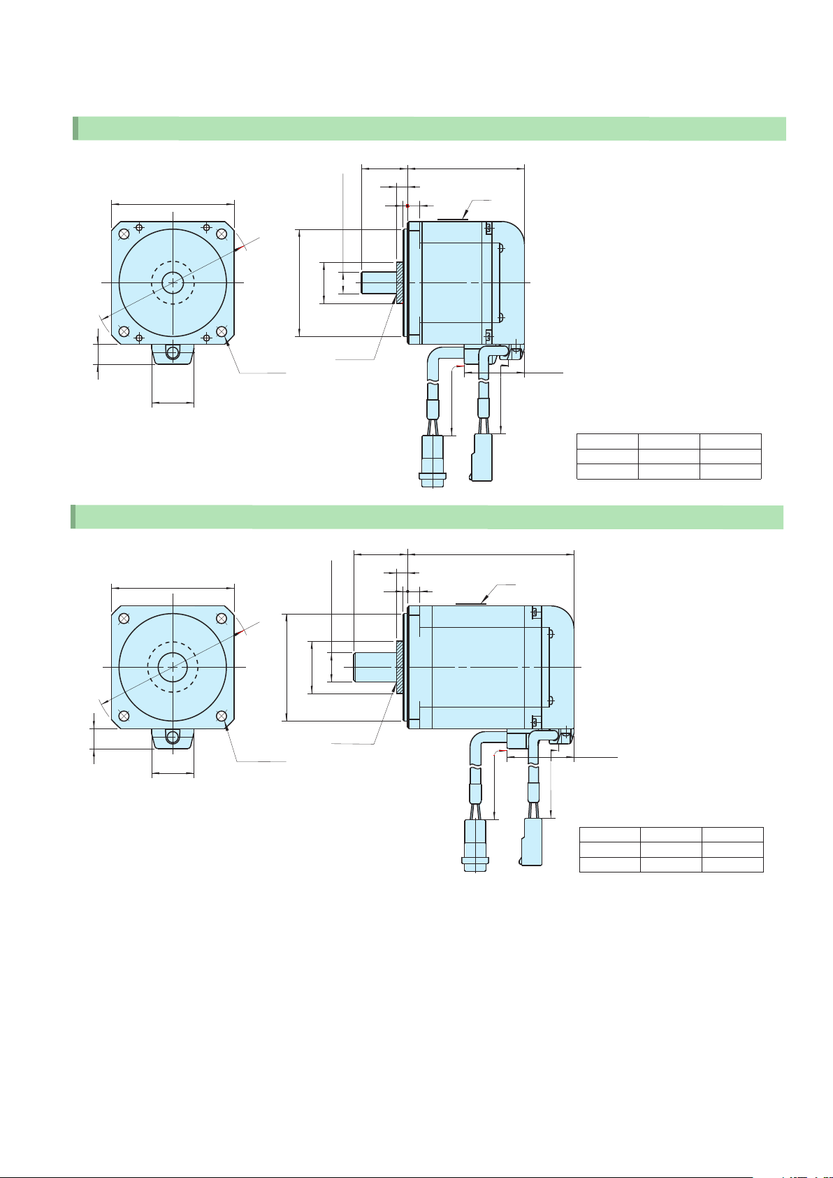
Compact
Dimensional Outline
Reliability
Simple
(Standard Type)
●□40 (30W,50W,100W)
□40
φ
55
)
(11.1
(21
2-φ4.5
PCD 46
)
●□60 (100W)
□60
0
−0.021
30h7
φ
equal division
φ80
0
−0.025
±1
25
)
(7
※
0
−0.009
2.5
8h 6
φ
)
20
(φ
※
(Oil seal)
0
−0.009
8h6
φ
)(φ
21
50h7
※
φ
5
±1
25
)(7
※
3
L
±50
300
Name plate
6
±1
Name plate
±50
300
±1
L
)(
39
L dimension
Rated output
Model
L(mm)
※Without oil seal, the shaded part is absent.
30W 50W
TS4601 TS4602
(Unit:mm)
100W
TS4603
73.559.553.5
)(13
4-φ5.5
PCD 70
)(27.6
●□60 (200W,400W)
□60
□
φ
)
13
(
)
(
27.6
4-φ5.5
PCD 70
PCD 70
equal division
80
0
−0.025
50h7
φ
equal division4-φ5.5
(Oil seal)
0
)
27
(φ
※
−0.011
14h6
φ
(Oil seal)
)(40.2
±50
300
±1
30
※
)(
7
3
6
±50
300
L
Name plate
±50
300
L dimension
Rated output
Model
L(mm)
±1
)(42.8
±50
300
L dimension
Rated output
Model
L(mm)
200W
TS4607
76.1
100W
TS4606
59.8
400W
TS4609
98.1
31 32
●□80 (200W,400W)
□80
φ
105
0
−0.030
70h 7
φ
SV-NET Servo System
(Unit:mm)
0
−0.011
14 h6
φ
±1
30
)(
※
7
3
8
±1
L
Name plate
※Without oil seal, the shaded part is absent.
)
(φ27
※
)(13
4-φ6.6
PCD 90
)(27.6
●□80 (600W,750W)
□80
φ
)(
13
)(27.6
4-φ6.6
PCD 90
equal division
105
0
−0.030
70 h7
φ
equal division
)
34
(φ
※
(Oil seal)
0
−0.013
19 h6
φ
(Oil seal)
35
)(
39.2
±50
300
±1
)(
※
7
8
3
±50
300
±1
L
Name plate
±50
300
±50
300
L dimension
Rated output
Model
L(mm)
(
)
43.8
200W
TS4611
64.3
400W
TS4612
76.3
L dimension
Rated output
Model
L(mm)
600W
TS4613
99.7
750W
TS4614
108.7

Compact
Dimensional Outline
Reliability
Simple
(Brake Type)
●□40 (30W,50W,100W)
□40
φ
55
)
(11.1
(21
2-φ4.5
PCD 46
)
●□60 (100W)
□60
0
−0.021
30h7
φ
equal division
φ80
±1
25
)
(7
※
0
−0.009
8h 6
φ
)
20
(φ
※
(Oil seal)
0
−0.009
8h6
φ
2.5
5
±50
±1
25
)(7
※
6
3
Name plate
300
L
Name plate
±1
L
±1
※Without oil seal, the shaded part is absent.
74.7()
±50
300
L dimension
Rated output
Model
L(mm)
89.1 95.1
50W30W
TS4602TS4601
(Unit:mm)
100W
TS4603
109.1
)(13
4-φ5.5
PCD 70
)(27.6
●□60 (200W,400W)
□60
φ80
0
−0.025
50h7
※
φ
equal division
0
−0.025
50h7
※
φ
)
21
(φ
(Oil seal)
0
27(φ )
−0.011
14 h6
φ
64.2()
±50
300
±1
30
※
7( )
3
6
±50
300
±1
L
Name plate
L dimension
Rated output
Model
L(mm)
100W
TS4606
83.8
)(13
equal division
4-φ5.5
PCD 70
)(27.6
(Oil seal)
±50
300
±50
300
( )
77.4
L dimension
Rated output
Model
L(mm)
200W
TS4607
110.7
400W
TS4609
132.7
33 34

●□80 (200W,400W)
□80
SV-NET Servo System
±1
30
※
0
−0.011
14 h 6
φ
105
0
−0.030
70 h7
φ
φ
)
27(φ
※
7( )
8
3
±1
L
Name plate
※Without oil seal, the shaded part is absent.
(Unit:mm)
)(13
)(27.6
●□80 (600W,750W)
□80
φ
)(
13
)(27.6
4-φ6.6
PCD 90
4-φ6.6
PCD 90
105
0
−0.030
70 h7
φ
equal division
(Oil seal)
equal division
0
−0.013
19 h6
φ
34(φ )
※
(Oil seal)
70.2()
±50
300
±1
35
7( )
※
3
8
Name plate
±50
300
L dimension
Rated output
Model
L(mm)
±1
L
200W
TS4611
95.3
400W
TS4612
107.3
80.4( )
±50
300
±50
300
L dimension
Rated output
Model
L(mm)
600W
TS4613
136.3
750W
TS4614
145.3

Compact
Reliability
Simple
AC Servo Motor
AC Servo Motor
Optimal replacement for
step motors
Servo motors mechanically compatible with step motors
The TBL-V series AC servo motors have the same flange size as
that of step motors. Hence, they can be installed in replacement of
such step motors.
(Note : The installation dimensions of step motors may vary by makers. Check the drawing for details.)
VR resolver
The VR resolver is of a simple structure with fewer parts than the
brushless resolver. lt features lower cost and even higher reliability.
Motor Characteristics
Power supply voltage
Motor flange size
Motor model
Rated output
Rated torque
Stall torque
Momentary max. torque
Rated rotation speed
Max. rotation speed
Rotor inertia
Rated power rate
Mechanical time constant
Shaft friction torque
Axial play
Allowable radial load
Allowable axial load
Power supply voltage
Motor flange size
Motor model
Rated output
Rated torque
Stall torque
Momentary max. torque
Rated rotation speed
Max. rotation speed
Rotor inertia
Rated power rate
Mechanical time constant
Shaft friction torque
PR
TR
TS
TP
NR
N MAX
J M
QR
τ
Tf
Axial play
Allowable radial load
Allowable axial load
i nch
m m
TS4742
PR
TR
TS
TP
NR
N MAX
J M
QR
τ
m
Tf
W
N・m
N・m
N・m
ー1
min
ー1
min
kg・m
kW/s
ms
N・m MAX
mm MAX
N
N
2
0.031×10
0.095
0.095
5,000
8,000
0.005
i nch #17 #23 #34 #17 #23 #34
m m 42 56.4 86 42 56.4 86
TS4742
m
W
N・m
N・m
N・m
ー1
min
ー1
min
kg・m
kW/s
ms
N・m MAX
mm MAX
N
N
2
50
0.095
0.095
0.29
5,000
8,000
0.031×10
3.0
3.4
0.005
39.2
19.6
ー4
DC24V (E500) DC48V (E600)
#17
42
TS4746
50
0.29
ー4
0.093×10
3.0
3.7
39.2
19.2
AC100V (E100) AC200V (E200)
TS4746
100
0.19
0.19
0.57
5,000
8,000
ー4
0.093×10
3.9
3.1
0.02
0.1
58.8
29.4
98
0.19
0.19
0.57
4,900
6,200
3.9
3.8
0.02
0.1
58.8
29.4
TS4747
200
0.38
0.38
1.15
5,000
8,000
0.182×10
8.0
2.3
0.02
58.8
29.4
Low-voltage type
#23
56.4
TS4747
92
0.38
0.38
1.15
2,300
2,900
ー4
0.182×10
8.0
2.3
0.02
58.8
29.4
High-voltage type
TS4752
320
0.76
0.76
2.29
4,000
4,400
ー4
1.02×10
ー4
5.7
1.8
0.04
78.4
39.2
TS4742
0.095
0.095
0.29
5,000
8,000
ー4
0.031×10
0.005
39.2
19.6
TS4742
50
0.095
0.095
0.29
5,000
8,000
0.031×10
3.0
3.4
0.005
39.2
19.6
#17
42
50
3.0
3.7
ー4
TS4746
ー4
0.093×10
TS4746
100
0.19
0.19
0.57
5,000
8,000
0.093×10
3.9
3.1
0.02
58.8
29.4
100
0.19
0.19
0.57
5,000
8,000
3.9
3.8
0.02
0.1
58.8
29.4
TS4747
ー4
0.182×10
0.1
5,000
8,000
#23
56.4
TS4747
200
0.38
0.38
1.15
5,000
5,900
ー4
0.182×10
0.02
58.8
29.4
高電圧タイプ
TS4752
200
0.38
0.38
1.15
5,000
8,000
ー4
1.02×10
8.0
2.3
0.02
58.8
29.4
8.0
2.3
400
0.76
0.76
2.29
5.7
1.8
0.04
78.4
39.2
ー4
ー4
35

Reliability
Compact
Simple
Dimensional Outline
Basic Specifications
Mounting flange
[inch]
[mm]
#17 □42 TS4742 50
#23 □56.4
#34 □86
Model
TS4746
TS4747
TS4752
● #17 □42 (50W)
±0.1
□42
±0.1
□31
Output
98
100
92
200
320
400
Name plate
4- M3 Depth 6
Driver power voltage
[V][W]
DC24・DC48
AC100・AC200
DC24
DC48
AC100・AC200
DC24
DC48
AC100・AC200
AC100
AC200
±1
20
2
0
−0.008
5h6
φ
0
−0.021
22h 7
φ
65.3
±50
300
Rated torque
[N・m]
0.095
0.095
0.19
0.19
0.19
0.38
0.38
0.38
0.76
0.76
±1
Protective tube
±50
300
SV-NET Servo System
Max. torque
[N・m]
0.29
0.29
0.57
0.57
0.57
1.15
1.15
1.15
2.29
2.29
Rated rotation
speed
−1
[min ]
5,000
5,000
4,900
5,000
5,000
2,300
5,000
5,000
4,000
5,000
Max. rotation speed
[min ]
8,000
8,000
6,200
8,000
8,000
2,900
5,900
8,000
4,400
8,000
−1
(Unit:mm)
●#23 □56.4 (100W, 200W)
±0.1
□56.4
±0.1
47.14
□
Name plate
0
−0.025
38.1h7
φ
4-φ4.5
●#34 □86 (400W)
±0.2
□86
±0.1
□69.6
Name plate
0
−0.030
73.02h 7
φ
±1
20
1.6
5
0
−0.009
8h6
φ
±1
30
1.52
0
−0.011
14h 6
φ
8.5
±1
L
Protective tube
±50
300
117.3
±1
±50
300
L dimension
Rated output
Model
L(mm)
100W
TS4746
72.6
200W
TS4747
98.6
4-φ5.5
Protective tube
±50
300
±50
300
36

Compact
Reliability
Simple
Cables Specifications
Controller Power Cable
7
L
SV-NET Cables
● For TA8410/TA8411/TA8413/TA8433
734-105(WAGO)
5
4
3
19.7
2
1
13.4
● For TA8420
734-105(WAGO)
5
4
3
19.7
2
1
13.4
(50)
Device net cable
Length(L):Up to 20m specifiable in 10cm unit. N*001〜N*200
*=1:Connector on one end, *=2:Connectors on both ends, *=0:No connectors on both ends
(50)
734-104(WAGO)
1
2
16.2
3
4
Length (L):0.1m〜20m specifiable
L
φ7
Model marking
L
φ7
Device net cable
Model marking
(50)
(50)
Housing:J21DF-10V- KY(JST)
Contact:SJ2 F-01GF- P1.0 (JST)
13.4
734-105(WAGO)
1
2
3
4
5
B A
1
2
3
4
5
16.0
Length (L):Up to 20m specifiable in 10cm unit. N1〜N200
EU9611
Model
EU9611 N 1 0.1m
N 10 1m
N100 10m
EU9610・EU9636
Model
EU9610 N*010 1m
N*030 3m
N*050 5m
N*100 10m
Model
EU9636 N 10 1m
13.9
N 30 3m
N 50 5m
N100 10 m
(Unit:mm)
Length(L)
Length(L)
Length(L)
Driver Drive Power Cables
● For TA8410/TA8411/TA8420
● For TA8410/TA8413
1
2
Housing:5557- 02R (MO LEX)
Terminal:5556 (MO LEX)
(7)
EU 9613 N0□□□□
Note : □□□ cable length L specified.
L
UL1007 AWG18
Length (L):Up to 20m specifiable in 10cm unit. N1〜N200
L
EU 9613 N1□□□□
Note : □□□ cable length L specified.
UL1007 AWG18
Length (L):Up to 20m specifiable in 10cm unit. N1001〜N1200
Serial Communication Cable
● For TA8440 (for upgrading firmware)/TA8413/TA8433
Modular plug
10.5
1
9.5
6
6.7
L
Model marking
5.4
1
2
14.1
Housing:5557- 02R (MO LEX)
Terminal:5556 (MO LEX)
1
2
Housing:5557- 02R (MO LEX)
Terminal:5556 (MO LEX)
PC-side
D-S U B 9 pins RS232C connection
17J E-13090 -02 (D8A) A-CG (JAE)
15.4
EU9613
Model
EU9613 N 10 1m
N 30 3m
N 50 5m
N100 10m
Model
EU9613 N1010 1m
N1030 3m
N1050 5m
N1100 10m
EU6517
Model
EU6517 N2 2m
N3 3m
N5 5m
32.3
Length(L)
Length(L)
Length(L)
Motor Cable
● For TA8410/TA8420 (Motor TBL- i Il series)
Motor-side
Receptacle 178289 -3 (AM P)
Receptacle contact 175218-2 (AMP) For U,V,W, FG
12.2
A3
B3
A2
24.4
B2
A1
B1
37
(20) L
Crosslinked PVC cable
φ6.7
Length (L):Up to 20m specifiable in 10cm unit. N1〜N200
Model marking
Driver-side
Receptacle housing 5557- 06 (MO LE X)
Terminal 5556T L (M OLE X)
(20)
14.1
3
6
2
5
1
4
EU9614
Model
EU9614 N 10 1m
N 30 3m
N 50 5m
N100 10m
13.8
Length(L)

(Unit:mm)
Motor Cables
● For TA8410/TA8420 (Motor TBL-V series)
Motor-side
Receptacle housing 5559- 06P (M O LE X)
Terminal 5558T L (MO LE X)
6
3
5
2
4
1
● For TA8411 (Motor TBL-i Il series)
Motor-side
Receptacle housing 178289-3 (AM P)
Receptacle contact 175218-2 (AM P) for U, V,W, FG
Receptacle contact 175217-2 (AM P) for BK
● For TA8411 (Moror TBL-V series)
Motor-side
Housing 5559-06P (MOLEX)
Contact 5558TL (MOLEX)
23.7
11.6
(25)
(20)
Crosslinked PVC cable
Heat-shrink
Sumitube F2Z
(20) L
Crosslinked PVC cable
(25)
(20)
Heat-shrink
Sumitube W3F2
Length (L):Up to 20m specifiable in 10cm unit. N1〜N200
φ6.7
φ6.7
Length (L):Up to 20m specifiable in 10cm unit. N1〜N200
Crosslinked PVC cable
Tepra (model marking)
φ6.7
Length (L):Up to 20m specifiable in 10cm unit. N1〜N200
L
Model marking
EU9621N0***
Model marking
L
Heat-shrink
Sumitube V
EU9621・
Driver-side
Receptacle 5557- 06 (M O L EX)
Terminal 5556T L (M OLE X)
(20)
(25)
6
5
4
Driver-side
Receptacle housing 1-178129-6 (AM P)
Receptacle contact 175218 -2 (AM P) for U, V, W, FG
Receptacle contact 175217-2 (AM P) for B K
Driver-side
Receptacle housing 1-178129-6 (AM P)
Receptacle contact 175218 -2 (AM P) for U, V, W, FG
Receptacle contact 175217-2 (AM P) for B K
(10)
(20)
(25)
(20)
Heat-shrink
Sumitube W3F2
14.8
EU9635・EU9638
Model
EU9621 N 10 1m
N 30 3m
3
2
1
27.3
N 50 5m
N100 10m
Model
EU9635 N 10 1m
N 30 3m
N 50 5m
N100 10m
Model
EU9638 N 10 1m
N 30 3m
N 50 5m
N100 10m
Length(L)
Length(L)
Length(L)
Sensor Cables
● For TA8410/TA8411 (Motor TBL-i Il series)
Motor-side
Receptacle housing 1-1318118-6 (AMP)
Receptacle contact 1318108-1 (AMP) for A1-A4, B1-B4
Receptacle contact 1318107-1 (AM P) for A5, B5, B6
B6
A6
B5
A5
B4
A4
B3
A3
16.4
B2
A2
B1
A1
14.8
● For TA8410 (Motor TBL-V series)
Motor-side
Tab housing 1-1318115-6 (AMP)
Tab contact 1318112-1 (AMP)
B1
A1
B2
A2
B3
A3
B4
A4
17.7
B5
A5
B6
A6
14.7
● For TA8420 (Motor TBL-V series)
Sensor-side
Tab housing 1-1318115-6 (AMP)
Tab contact 1318112-1 (AMP)
B1
A1
B2
A2
B3
A3
B4
A4
B5
A5
B6
A6
● For TA8420 (Motor TBL- i Il series)
Sensor-side
Receptacle housing 1-1318118-6 (AMP)
Receptacle contact 1318108-1 (AMP) for A1-A4, B1-B4
Receptacle contact 1318107-1 (AM P) for A5, B5, B6
A6
A5
A4
A3
A2
A1
Heat-shrink
Sumitube F2Z
B6
B5
B4
B3
B2
B1
(20)
Crosslinked PVC cable
(20)
Crosslinked PVC cable
(25)
(20)
Crosslinked PVC
cable
(25) (25)
(20)
Heat-shrink
Sumitube F2Z
Connection marking
Length (L):Up to 20m specifiable in 10cm unit. N1〜N200
φ6.3
φ6.3
Length (L):Up to 20m specifiable in 10cm unit. N1〜N200
Length (L):Up to 20m specifiable in 10cm unit. N1〜N200
Crosslinked PVC cable
(10)
SENSOR
Model marking
Connection marking
Length (L):Up to 20m specifiable in 10cm unit. N1〜N200
L
L
Model marking
φ6.3
L
φ6.3
L
Model marking
Model marking
(55)
EU9645N0***
(55)
EU9646N0***
EU9615・EU9622・
Driver-side
Receptacle housing 1-1318118-6 (AM P)
Receptacle contact 1318108-1 (AM P) for A1-A4, B1-B4
Receptacle contact 1318107-1 (AM P) for A5, B5, B6
(10)
Driver-side
Receptacle housing 1-1318118-6 (AM P)
Receptacle contact 1318108-1 (AM P) for A1-A4, B1-B4
Receptacle contact 1318107-1 (AM P) for A5, B5, B6
(10)
(10)
(15) (25)
AM P
(20)
Driver-side
Receptacle housing 1-1318118-6 (AM P)
Receptacle contact 1318108-1 (AM P)
(20)
B1
B2
B3
B4
B5
B6
Driver-side
Receptacle housing 1-1318118-6 (AM P)
Receptacle contact 1318108-1 (AM P)
(20)
(25)
Heat-shrink
Sumitube F2Z
(20)
Heat-shrink
Sumitube F2Z
B1
B2
B3
B4
B5
B6
B1
B2
B3
B4
B5
B6
B6
B5
B4
B3
B2
B1
EU9645・EU9646
Model
EU9615 N 10 1m
N 30 3m
N 50 5m
A6
A5
A4
A3
A2
A1
A1
A2
A3
A4
A5
A6
A1
A2
A3
A4
A5
A6
A1
A2
A3
A4
A5
A6
N100 10m
Model
EU9622 N 10 1m
N 30 3m
N 50 5m
N100 10m
Model
EU9645 N 10 1m
N 30 3m
N 50 5m
N100 10m
形式 長さ(L)
EU9646 N 10 1m
N 30 3m
N 50 5m
N100 10m
Length(L)
Length(L)
Length(L)
38

HEAD OFFICE :
1879 Oyasumi, Iida City, Nagano-Pref., 395-8515 JAPAN
TEL : +81-265-21-1800
FAX : +81-265-21-1861
TAMAGAWA TRADING CO.,LTD.
■Overseas Sales Depart ment
1-595-1 Haba-cho, Iida City, Nagano-Pref., 395-0063 JAPAN
TEL : +81-265-56-5423
FAX : +81-265-56-5427
●
Internet website http : //ww w. tam ag awa- seiki. co. j p
●
SV-NET website http : //sv- net. ta magawa- se iki. com
The contents of this catalog are subject to change without notice.
,
08.7
T12-1655 1,000 2008.7
 Loading...