

Page 1

Digital Video Recorder User Manual
Digital Video Recorder
Page 2

Digital Video Recorder User Manual
Statement:
This manual may contain information that does not match the product. If you have any
unsolved problems in the process of using this product according to this manual,
please contact our technical support department.
The content of this manual may be updated at irregular intervals without prior notice.
This manual is for reference only. DVR’s functions and operations with different
models may be different.
Caution:
Please read this user manual carefully before using the DVR, and retain it for future
reference.
Please comply with all instructions and notice all warning signs.
Observe all electrical safety standards; make sure the power supply voltage is
correct before using the DVR.
Please avoid heavy stress or violent vibration.
To reduce the risk of fire or electrical shock, do not expose this product near the
water, moisture or dust.
Do not install this device near any heat sources such as radiators, heat registers,
stoves or other device that produce heat.
Do not block any ventilation openings and provide good ventilation around the
machine.
Please disconnect any cables during an electrical storm or the DVR will not be used
for an extended period of time.
If cleaning is necessary, use a clean, dry cloth and wipe it gently.
If the product does not work properly, please contact your dealer or the nearest
service center. Never attempt to disassemble the DVR yourself.
Do not power off the DVR when the device is working. The correct procedure to shut
down DVR is to stop recording firstly, and then use “Shut Down” button from the
menu, and finally switching off the main power.
i
Page 3

Digital Video Recorder User Manual
Table of Contents
Chapter 1 Product Introduction ......................................................................................1
1.1 Overview ............................................................................................... 1
1.2 Main Features ........................................................................................ 1
Chapter 2 Installation Guide ............................................................................................4
2.1 Open-package Check .............................................................................. 4
2.2 Install Hard Drive .................................................................................... 4
2.3 Front Panel Description............................................................................ 5
2.4 Rear Panel Description ............................................................................ 6
2.5 Remote Controller ................................................................................... 8
2.6 Control with Mouse ............................................................................... 10
2.6.1 Connect Mouse .......................................................................... 10
2.6.2 Use Mouse ................................................................................ 10
Chapter 3 Basic Function Instruction.............................................................................2
3.1 Power On/Off ......................................................................................... 2
3.1.1 Power On .................................................................................... 2
3.1.2 Power Off .................................................................................... 2
3.2 Login..................................................................................................... 3
3.3 Live Preview .......................................................................................... 4
3.4 Live Playback ......................................................................................... 4
Chapter 4 Main Menu Setup Guide .................................................................................6
4.1 Control Menu ......................................................................................... 6
4.2 Basic Configuration ................................................................................. 8
4.2.1 System ........................................................................................ 8
4.2.2 Date & Time ................................................................................. 9
4.2.3 DST .......................................................................................... 10
4.3 Live Configuration ................................................................................. 10
4.3.1 Live .......................................................................................... 10
4.3.2 Main Monitor .............................................................................. 11
4.3.3 Mask ......................................................................................... 12
4.4 Record Configuration ............................................................................. 13
4.4.1 Enable ...................................................................................... 13
4.4.2 Record Bitrate ............................................................................ 14
4.4.3 Time ......................................................................................... 15
4.4.4 Stamp ....................................................................................... 16
4.4.5 Recycle Record .......................................................................... 17
4.4.6 Snap ......................................................................................... 17
4.5 Schedule Configuration .......................................................................... 18
4.5.1 Schedule ................................................................................... 18
ii
Page 4

Digital Video Recorder User Manual
4.5.2 Motion ....................................................................................... 20
4.5.3 Sensor ...................................................................................... 20
4.5.4 Reboot the System ...................................................................... 21
4.6 Alarm Configuration ............................................................................... 22
4.6.1 Sensor ...................................................................................... 22
4.6.2 Motion ....................................................................................... 25
4.6.3 Video Loss ................................................................................. 27
4.6.4 Other Alarm................................................................................ 28
4.6.5 Alarm Out .................................................................................. 29
4.7 Network Configuration ........................................................................... 30
4.7.1 Network ..................................................................................... 30
4.7.2 Sub-stream ................................................................................ 31
4.7.3 Email ........................................................................................ 33
4.7.4 WIFI Setup ................................................................................. 34
4.7.5 Other Settings ............................................................................ 34
4.8 User Management Configuration ............................................................. 40
4.9 P.T.Z Configuration ................................................................................ 42
4.9.1 Serial Port .................................................................................. 42
4.9.2 Advanced .................................................................................. 43
4.10 Advanced Configuration ....................................................................... 47
4.10.1 Reset ...................................................................................... 47
4.10.2 Import/Export ............................................................................ 47
Chapter 5 Manage DVR .................................................................................................. 48
5.1 Search and Playback ............................................................................. 48
5.1.1 Time Search ............................................................................... 48
5.1.2 Event Search ............................................................................. 49
5.1.3 File Management ........................................................................ 50
5.1.4 Image........................................................................................ 51
5.2 Backup ................................................................................................ 52
5.3 Information ........................................................................................... 53
5.3.1 System Information ..................................................................... 53
5.3.2 Event Information ........................................................................ 53
5.3.3 Log Information .......................................................................... 53
5.3.4 Network Information .................................................................... 53
5.3.5 Online Users Information .............................................................. 54
5.4 Manual Alarm ....................................................................................... 54
5.5 Disk Management ................................................................................. 54
5.5.1 Format Disk ............................................................................... 54
5.5.2 Advanced .................................................................................. 55
5.6 Upgrade .............................................................................................. 55
5.7 Logoff .................................................................................................. 55
iii
Page 5

Digital Video Recorder User Manual
Chapter 6 Remote Surveillance .................................................................................... 56
6.1 IE Remote Surveillance.......................................................................... 56
6.1.1 On LAN ..................................................................................... 56
6.1.2 On WAN .................................................................................... 57
6.2 Remote Live Preview ............................................................................. 59
6.2.1 Symbol and Function Definition ..................................................... 60
6.2.2 Snap Picture .............................................................................. 60
6.2.3 Color Adjustment ........................................................................ 60
6.2.4 PTZ Control ............................................................................... 61
6.2.5 Preview Control .......................................................................... 62
6.3 Remote Playback & Backup ................................................................... 62
6.3.1 Time Search ............................................................................... 62
6.3.2 Event Search ............................................................................. 64
6.3.3 File Management ........................................................................ 65
6.3.4 Remote backup .......................................................................... 67
6.4 Remote Configuration & Management ...................................................... 68
6.4.1 Remote Configuration .................................................................. 68
6.4.2 Remote Management .................................................................. 68
6.4.3 Remote Check Information ........................................................... 69
Chapter 7 Mobile Surveillance ...................................................................................... 70
For Android ............................................................................................... 71
7.1 Main Functions ..................................................................................... 71
7.2 Installation ........................................................................................... 71
7.3 Application Running ............................................................................... 72
7.3.1 Interface Description.................................................................... 72
7.3.2 Live Preview .............................................................................. 74
7.3.3 Add Device ................................................................................ 75
7.3.4 Switch Channel .......................................................................... 77
7.3.5 PTZ Control ............................................................................... 79
7.3.6 Local Video ................................................................................ 79
7.3.7 Saved Photos ............................................................................. 81
7.3.8 Switch Language ........................................................................ 81
7.3.9 Video Remote ............................................................................ 81
7.3.10 Real-Time Alarm ....................................................................... 81
For Iphone ................................................................................................ 82
7.4 Main Functions ..................................................................................... 82
7.5 Installation ........................................................................................... 83
7.6 Application Running ............................................................................... 84
7.6.1 Interface Description.................................................................... 84
7.6.2 Live Preview .............................................................................. 86
7.6.3 Add Device ................................................................................ 87
iv
Page 6

Digital Video Recorder User Manual
7.6.4 Switch Channel .......................................................................... 88
7.6.5 PTZ Control ............................................................................... 89
7.6.6 Local Video ................................................................................ 90
7.6.7 Saved Photos ............................................................................. 91
7.6.8 Switch Language ........................................................................ 92
7.6.9 Video Remote ............................................................................ 92
7.6.10 Real-Time Alarm ....................................................................... 92
Appendix A FAQ ........................................................................................................ 93
Appendix B Calculate Recording Capacity ............................................................. 98
Appendix C Compatible Devices .............................................................................. 99
Appendix D Specifications ...................................................................................... 101
v
Page 7

Digital Video Recorder User Manual
Chapter 1 Product Introduction
1.1 Overview
This model of DVR (Digital Video Recorder) is designed for high performance CCTV
solutions. It adopts state of the art video processing chips and embedded Linux system.
Meanwhile, it utilizes most advanced technologies, such as standard H.264 with low bit
rate, Dual stream, HDMI interface, SATA interface, VGA output, mouse supported, IE
browser supported with full remote control, mobile view(by phones), etc., ensuring
powerful functions and high stability. Due to these distinctive characteristics, it is widely
used in banks, telecommunication, transportation, factories, warehouse and other related
applications.
1.2 Main Features
COMPRESSION FORMAT
Standard H.264 compression with low bit rate and better image quality
LIVE SURVEILLANCE
Support HDMI 1080P output
Support channel security by hiding live display
Display the local record state and basic information
Support USB mouse to make full control
RECORD MEDIA
Support a SATA HDD to record (HDD file system is FAT32 format) continuously.
1
Page 8

Digital Video Recorder User Manual
BACKUP
Supports USB 2.0 devices to backup
Supports saving recorded files to a remote computer through internet
RECORD & PLAYBACK
Record modes: Manual, Schedule, Motion detection and Sensor alarm recording
Supports recycle after HDD full
Supports high-definition 1080P video output, and D1/960H video recording
Resolution, frame rate and picture quality are adjustable
4 audio channels
Supports multi-channel playback simultaneously
Supports deleting and locking the recorded files one by one
Three search modes: time search, event search and image search
Supports remote playback in Network Client through LAN or internet
ALARM
Supports multi-channel alarm input and alarm output available
Supports schedule for Motion detection and Sensor alarm
Supports pre-alarm recording and post-alarm recording
Supports linked channels recording once motion or alarm triggered
Supports linked PTZ preset, auto cruise and track of the corresponding channel
Supports linked snap picture
Supports linked send alarm email
PTZ CONTROL
Supports various PTZ protocols
Supports 128 PTZ presets and 8 auto cruise tracks
Supports remote PTZ control through internet
2
Page 9

Digital Video Recorder User Manual
SECURITY
Customize user privileges: log search, system setup, shut down, two way audio,
file management, disk management, remote login, live view, manual record,
playback, backup, PTZ control and remote live view
Supports 1 administrator and 63 users
Supports event log recording and checking
NETWORK
Supports TCP/IP, DHCP, PPPoE, DDNS protocol
Supports browser remote viewing
Supports setup client connection
Supports dual streams adjustable to fit your network bandwidth and environment
Supports picture snap and color adjustment in remote live
Supports remote time and event search, and channel playback with picture snap
Supports remote PTZ control with preset and auto cruise
Supports full menu remote setup, changing all the DVR parameters remotely
Supports mobile surveillance by iPhone, iPad and Android OS.
Supports CMS to manage multi devices remotely
3
Page 10

Digital Video Recorder User Manual
Chapter 2 Installation Guide
2.1 Open-package Check
When you receive the DVR, please check the unit and the accessories:
First, please check whether there is any visible damage to the package appearance.
The protective materials used for the package of the DVR can protect most accidental
clashes during transportation.
Then, please open the box and get rid of the plastic protective materials. Check
whether there is any visible damage to the DVR appearance.
Front panel and rear panel
The key function specification in the front panel and the interface specification in the
rear panel are in the user manual.
Please check the product type in the front panel whether is accordant with the
product type you order.
Notice:
1. The label in the rear panel is very important for the after-sale services. Please
protect it carefully. When you contact us for after-sale service, please provide the
product type and serial number on the label.
2. Please disconnect the power before being connected to other devices. Don't hot
plug in/out.
2.2 Install Hard Drive
Notice: FOR REPAIR PURPOSES ONLY
1. This series support a SATA hard drive. Please use the hard drive
recommended by the manufacturers for security and safe field. Please refer to
4
Page 11
Digital Video Recorder User Manual
“Appendix C Compatible Devices 2”.
2. Please calculate HDD capacity according to the recording setting. Please refer to
“Appendix B Calculate Recording Capacity”.
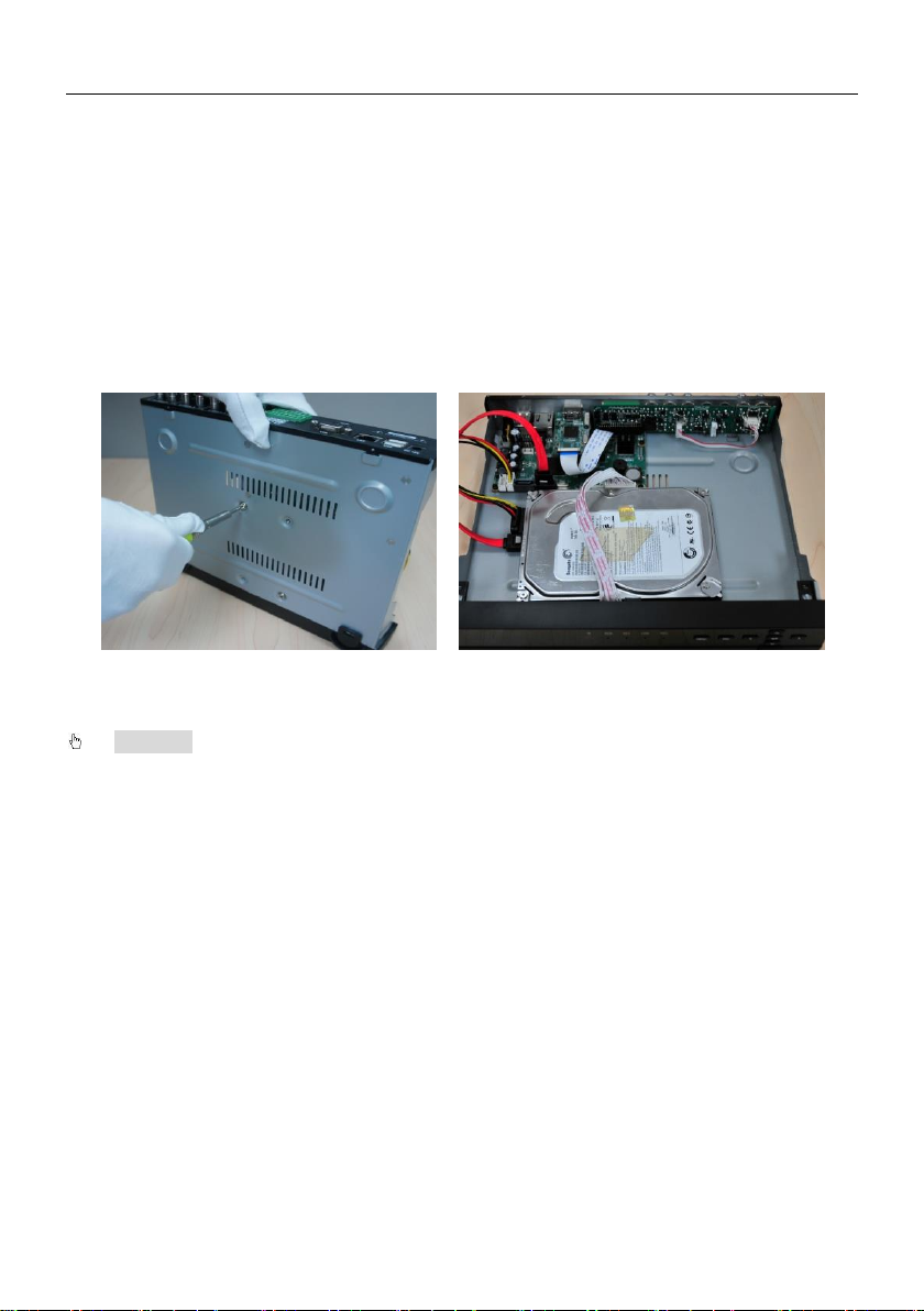
Step1: Disassemble the screw and open the top cover.
Step2: Connect the power and data cables. Place the HDD onto the bottom case as
Fig 2-1.
Step3: Mount the HDD.
Fig 0-1 Connect HDD
Notice:
1. For installation please connect the power and data cables first, and then the
screws to secure the HDD.
2. After the hard drive installation is complete format the HDD before using.
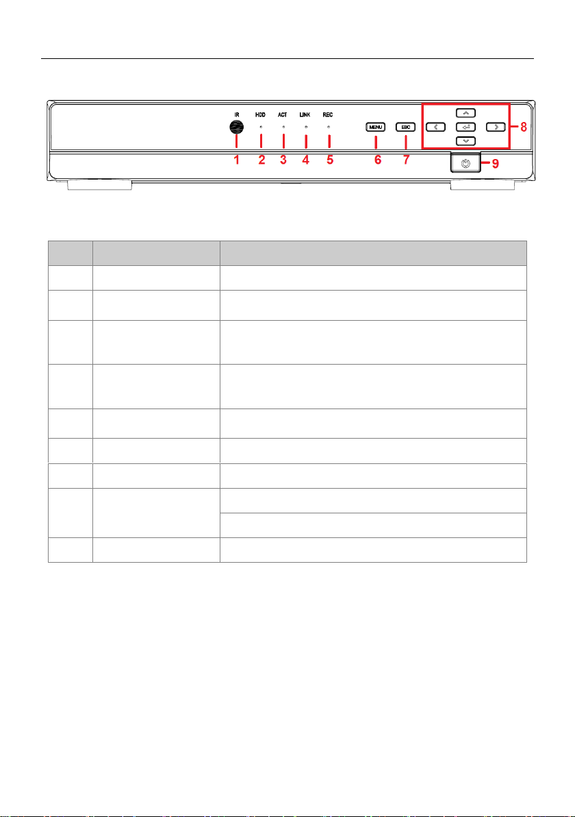
2.3 Front Panel Description
Note:The front panel descriptions are only for reference; please make the
object as the standard.
5
Page 12
Digital Video Recorder User Manual
Item
Name
Description
1
IR
Receive the signal of remote controller.
2
HDD
Hard disk status indicator.
When HDD is writing or reading, the light is white.
3
ACT
Network data indicator.
When exchanging data in the network, the light is
white.
4
LINK
Network connection indicator.
When the network connection is successful, the light
is white.
5
REC
Recording status indicator.
When recording, the light is white.
6
MENU
Enter menu mode.
7
ESC
Return to the previous menu or interface.
8
Direction and Enter
Direction keys: change direction to select items.
Enter key: confirm selection.
9
Power
Power on/off the DVR.
The descriptions of front panel interface are shown as follows:
Fig 0-2 Front Panel
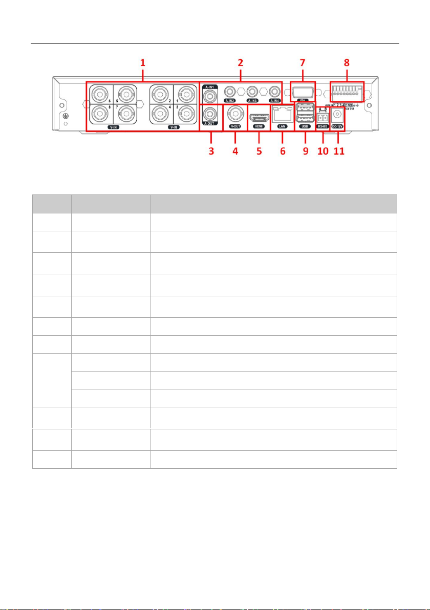
2.4 Rear Panel Description
Note: The rear panel descriptions are only for reference; please make the object
as the standard.
The descriptions of rear panel interface are shown as follows:
6
Page 13
Digital Video Recorder User Manual
Item
Name
Description
1
V-IN
Video signal input.
2
A-IN
Audio input: connect to pickup and other audio collecting
equipment.
3
A-OUT
Audio output: connect to sound box and other audio
output equipment.
4
V-OUT
CVBS video signal output: connect to monitor with BNC
interface.
5
HDMI port
HD 1080P video signal output: connect to high-definition
display.
6
LAN port
Network connector.
7
VGA port
VGA output: connect to monitor.
8
ALM IN
Alarm input: connect to external alarm sensor.
ALM OUT
Alarm output: connect to external alarm output device.
GND
Grounding
9
USB port
USB connector: connect to USB mouse, USB disk, mobile
HDD, etc.
10
RS-485
RS-485 communication port: connect to PTZ, keyboard,
etc.
11
DC 12V
Power input: DC 12V
Fig 0-3 Rear Panel
7
Page 14
Digital Video Recorder User Manual
Item
Name
Function
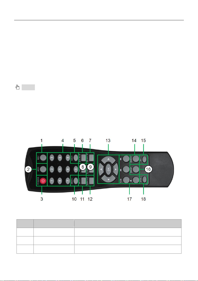
1
REC Button
To start the manual recording.
2
ADD Button
Input the number of DVR to control it.
3
POWER Button
To turn on/off the device.
2.5 Remote Control
The remote controller of this product series uses two AAA size batteries:
Step 1: Open the battery cover of the remote controller
Step 2: Place batteries. Please take care the poles (+ and -)
Step 3: Replace the battery cover
Notice: Frequently defect checking as following:
1. Check batteries poles
2. Check the remaining charge in the batteries
3. Check IR controller sensor is mask
If it still doesn't work, please change a new remote controller to try, or contact your
dealers.
The interface of remote controller is shown in Fig 2-4:
Fig 0-4 Remote Controller
8
Page 15

Digital Video Recorder User Manual
Item
Name
Function
4
Digital Button
Code input/number input/channel switch.
5
EXIT Button
Return to the previous interface.
6
BACKUP Button
To enter the backup mode.
7
SEARCH Button
To enter the video playback interface.
8
SEQ Button
To enter the auto dwell mode.
9
E-ZOOM Button
To electronic amplify the single channel.
10
MENU Button
To enter the sub menu.
11
Multi Screen
Button
To choose multi-screen display mode.
12
Single Screen
Button
To choose single -screen display mode.
13
Direction and
Enter Button
Direction Button: move cursor to select items.
Enter Button: confirm the selection.
14
AUDIO Button
To enter the audio adjustment interface.
15
Fn Button
Reserved function keys.
16
SNAP Button
To snap the live pictures.
17
Playback Control
Button
To control playback, pause/play, single-frame play,
rewind, stop, fast forward.
18
PTZ Button
To enter the PTZ control interface.
Operation processes with remote controller to control multi-DVR
The default device ID of the DVR is 0. When using a remote controller to control
single DVR, it’s not necessary to reset the device ID, user can do operation directly;
when using a remote controller to control multiple DVR, please refer to below steps:
Step 1: Activate remote controller to control DVR: enable DVR, turn the IR sensor of
the remote controller to the IR receiver that on the front panel, press “add” key and
then input device ID (Range from: 1-65535) with other digital keys, after that, press
ENTER button to confirm.
Step 2: User can check the device ID by enter into System configurationBasic
configurationdevice ID. User also can set other DVRs with the same device ID. For
more convenient to operate, we don’t recommend user to set the device ID too long.
9
Page 16
Digital Video Recorder User Manual
Step 3: Cancel controller to control DVR: without any action on keys about half a
minute later, the DVR will not be controlled by remote controller.
2.6 Control with Mouse
2.6.1 Connect Mouse
It supports USB mouse through the USB ports.
Note: If mouse is not detected or doesn't work, try another mouse.
2.6.2 Use Mouse
In live: Double-click left button on one camera to be full screen display. Double-click
again to return to the previous screen display.
Click right button to show the control menu at the bottom right of cursor. Here you will
find all the controls and setup options. Click right mouse again to hide the control
menu.
In setup: Click left button to enter.
Click right button to cancel setup, or
return to the previous.
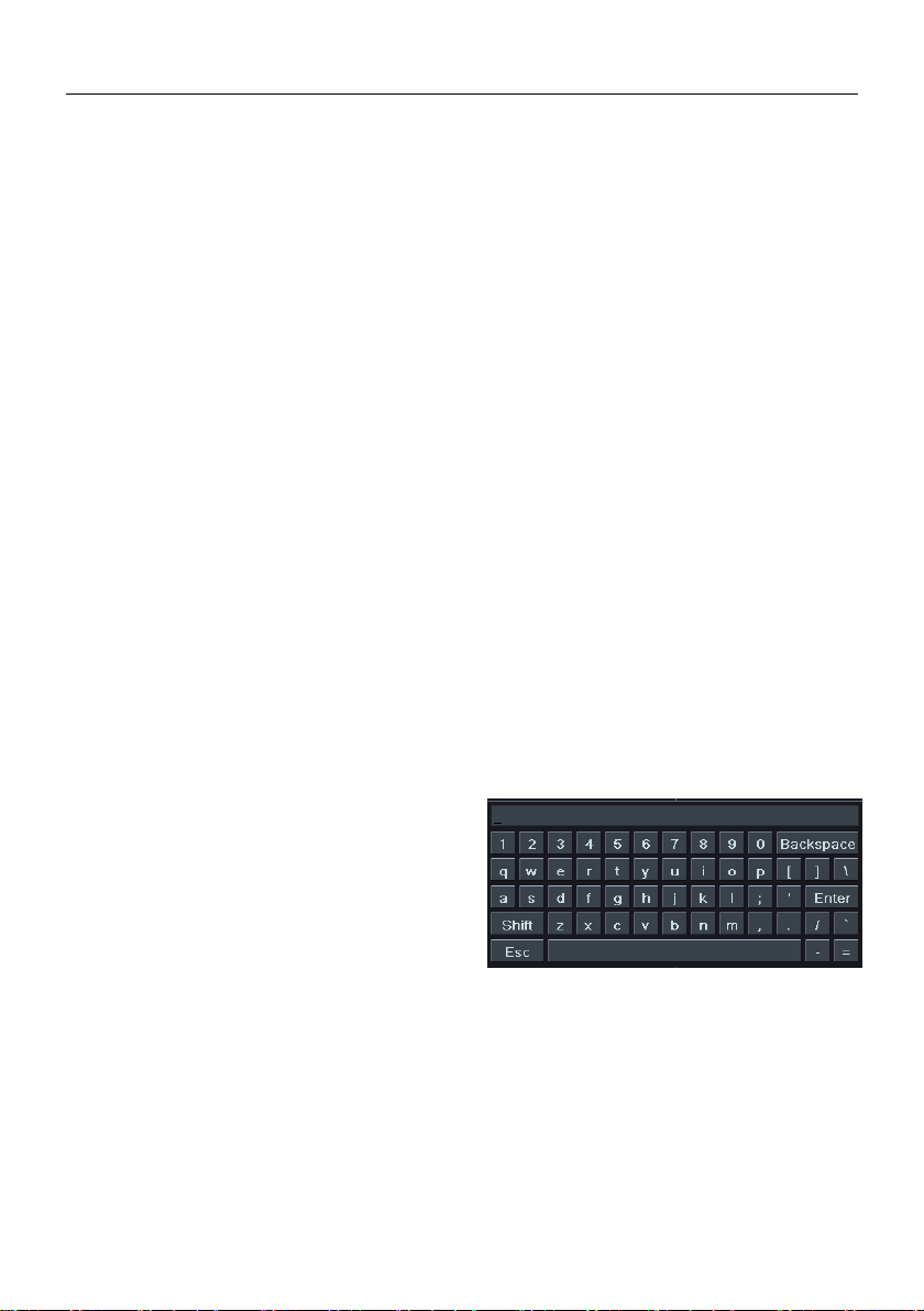
If want to input the value, move
cursor to the blank and click. An input
window will appear as Fig2-5. It
supports digitals, letters and symbols
It supports mouse drag, I.e. set motion detection area: click customized, hold left
button and drag to set motion detection area.
In playback: Click left button to choose the options. Click right button to return to live
mode.
In backup: Click left button to choose the options. Click right button to return to
previous picture.
input.
Fig 2-5 Input Window
10
Page 17

Digital Video Recorder User Manual
In PTZ control: Click left button to choose the buttons to control the PTZ. Click right
button to return to live mode.
Note: Mouse is the default tool in all the operation below unless otherwise noted.
Chapter 3 Basic Functions
3.1 Power On/Off
3.1.1 Power On
Before you power on the unit, please verify all the connections.
Step 1: Connect with the source power; switch on the power button near the power
port in the rear panel.
Step 2: The device will be loaded, and the power indicator will display red.
Step 3: A WIZARD window will pop-up and display information about device name,
language, date and time, network, record, etc.
User can setup here and refer to the setup steps from the corresponding chapters. If
users don’t want to setup Wizard, please click Exit button and enter into the login
interface.
Notice: This series can only support the menu on VGA monitor, BNC monitor
or HDMI monitor at one time. After the device is power on, if there is live display
without the menu, please check the other outputs for the menu display, or press
Exit /ESC button (press and hold) to switch the output among BNC, HDMI and VGA.
3.1.2 Power Off
User can power off the device by using the remote control, keyboard or mouse
Using the remote control:
2
Page 18

Digital Video Recorder User Manual
Step 1: press Power button of remote controller to pop up Shut Down window.
Step 2: click OK, the unit will power off after a while.
Step 3: disconnect the power.
By mouse:
Step 1: enter into Main Menu and select Shut Down button to pop up Shut Down
window.
Step 2: Click OK, the unit will power off after a while.
Step 3: Disconnect the power.
3.2 Login
User can login and logout the DVR system. User cannot do any other operations
except changing the multi-screen display once logout.
Fig 3-1 Login
Notice:
The default user name and password is “admin” and blank.
The operation steps for changing the password, add or delete user: please
refer to 4.8 User Management Configuration for more details.
User permissions can be customized. Only administrators can customize other
user's permissions. The user name and password can consist of numbers, letters
or symbols (1~32 characters).
3
Page 19
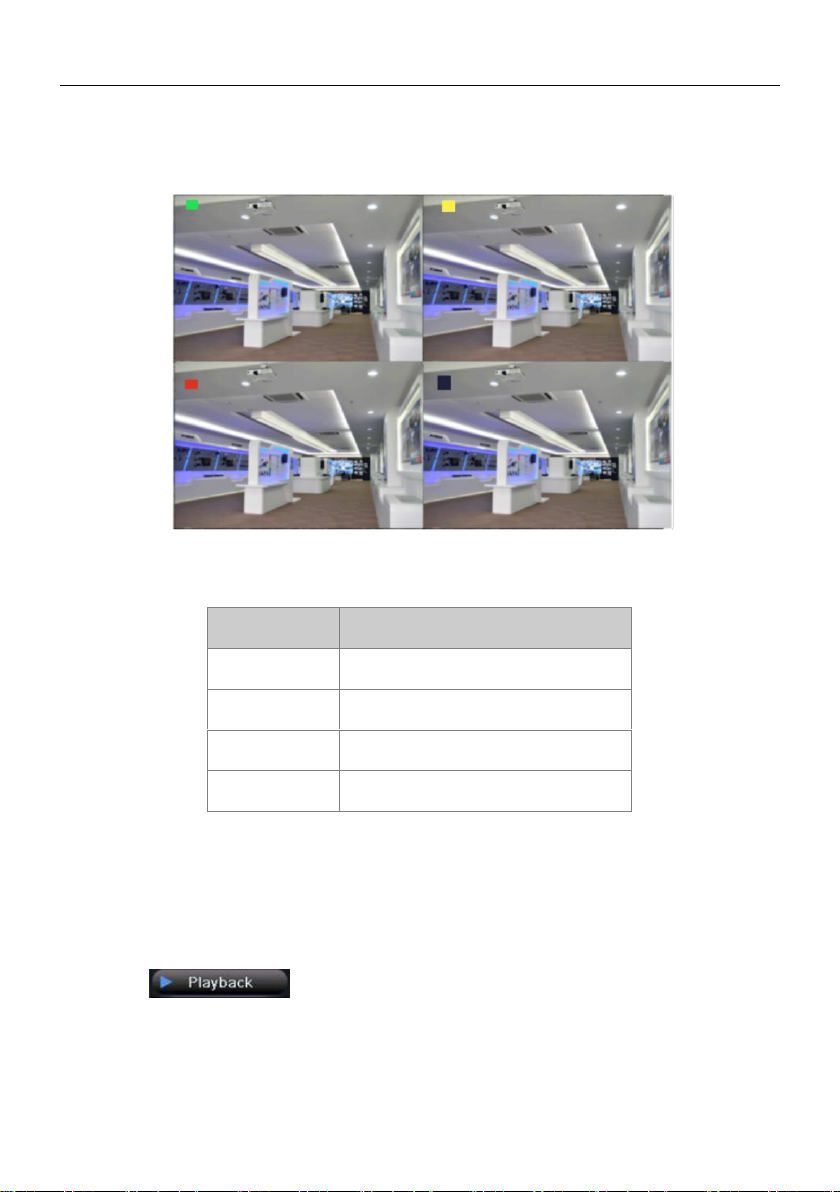
3.3 Live Preview
Symbol
Meaning
Green
Manual record
Yellow
Motion detection record
Red
Alarm record
Blue
Schedule record
Digital Video Recorder User Manual
Fig 3-2 live preview interface
3.4 Live Playback
Click of control menu to playback the recordings, refer to Fig3-3.
User can click the control buttons on the screen to change operation.
4
Page 20
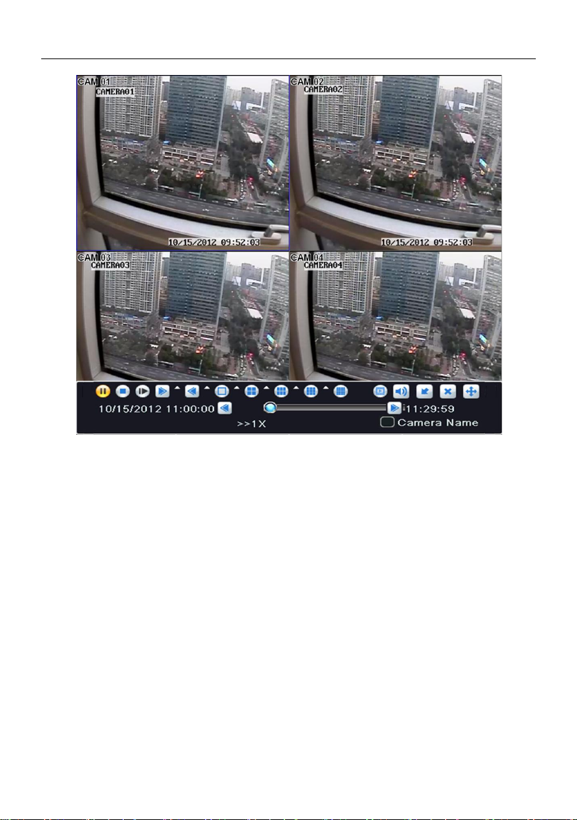
Digital Video Recorder User Manual
Fig 3-3 live playback
5
Page 21
Digital Video Recorder User Manual
Chapter 4 Main Menu Setup Guide
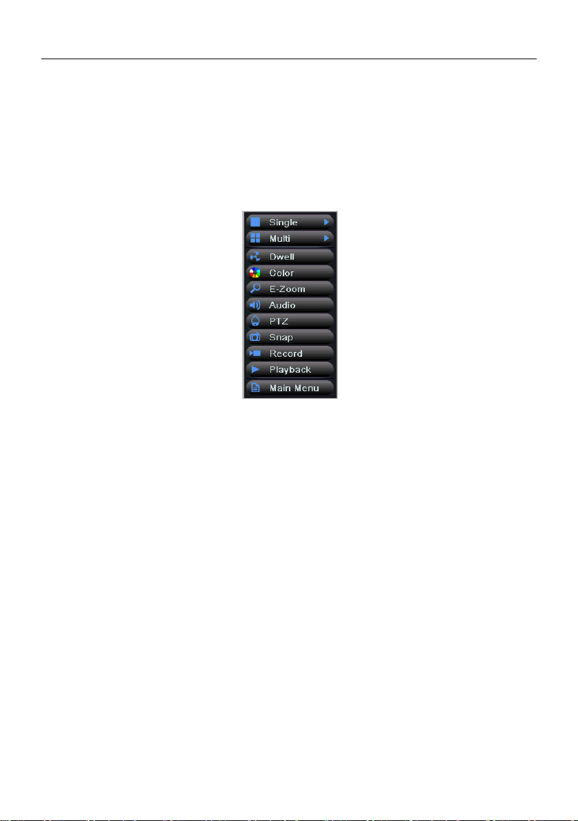
4.1 Control Menu
Right click to display the control menu, refer to Fig 4-1:
Fig 4-1 control menu
Single: Click this button to pop up the single channel selection box.
Multi: Click this button to pop up the multi-channel selection box. The range of options
synchronizes with configured device. Images can be dragged to any place to display in the
live interface.
Dwell: Display the preview pictures in the dwell mode. The range of options synchronizes
with configured device. Only takes effect when user has selected channel grouping and
preview mode cannot display all channels.
Color: Click this button, select channel and adjust the brightness, hue, saturation and
contrast of live pictures. Click “Default” button to resort default setting; click “Save” button
to save the setting.
E-Zoom: Zoom in to the video of channel (optional), double click the left button or click the
right button to return to the previous interface.
Audio: Open or close the live sound of channel (optional), and adjust the volume.
PTZ: Control PTZ rotational position and speed; zoom, focus and iris are adjustable; run
the preset, cruise and auto scan.
Snap: Click this button to snap current image.
6
Page 22
Digital Video Recorder User Manual
Record: Click this button to record current video.
Playback: Click this button to playback the recorded files; click the relevant buttons on the
screen to control playback.
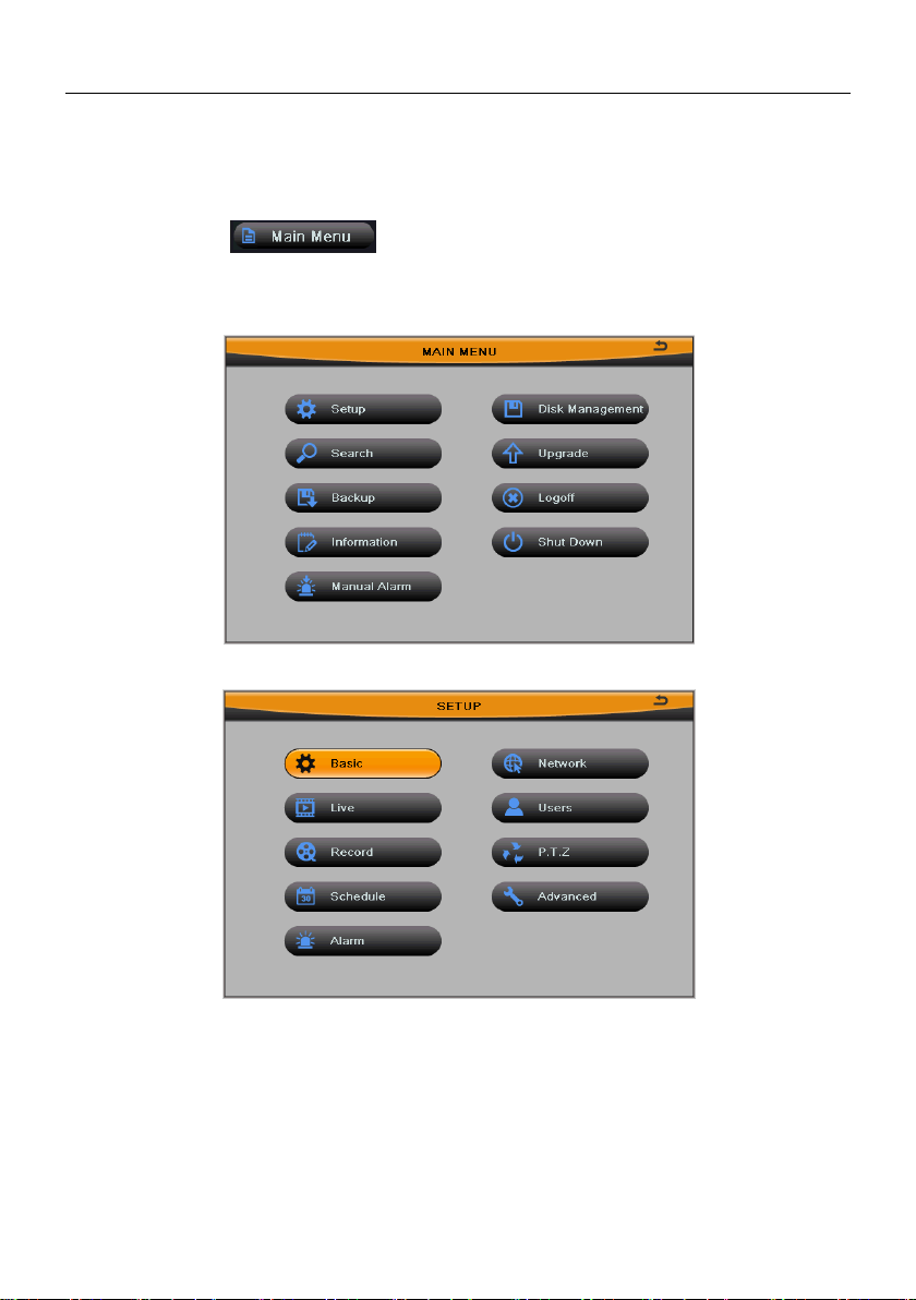
Main Menu: Click button to pop up the window shown in Fig 4-2; then
click Setup button to pop up the window shown in Fig 4-3.
Fig 4-2 main menu
Fig 4-3 setup menu
Press MENU button on the front panel or operate with remote controller also can
display the main menu.
SETUP configuration includes nine submenus: basic, live, record, schedule, alarm,
network, users, P.T.Z and advanced.
7
Page 23
Digital Video Recorder User Manual
4.2 Basic Configuration
Basic configuration includes three submenus: system date & time and DST.
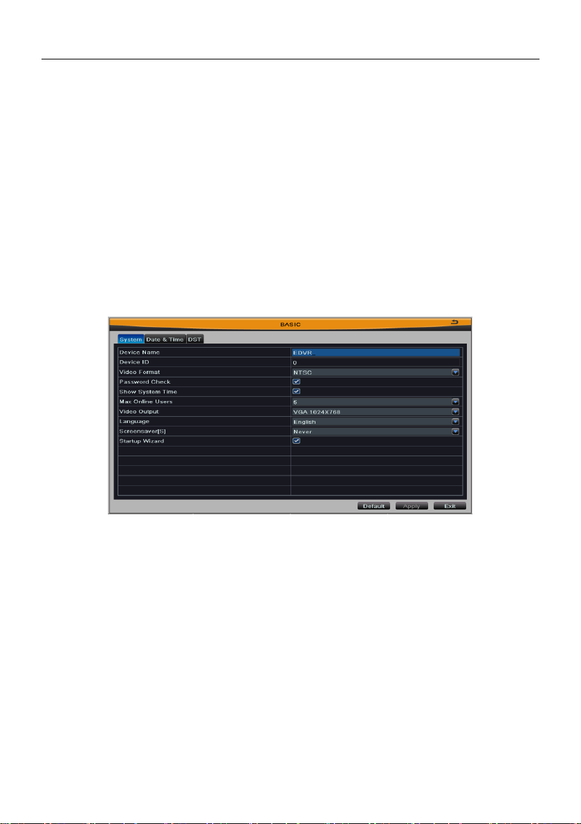
4.2.1 System
Enter into Main MenuSetupBasicSystem; refer to Fig 4-4:
User can setup the device name, device ID, video format, max online users, video
output, language, etc.
Fig 4-4 basic configuration-system
Device Name/ID: The name/ID of device. It may display on the client end or CMS that
help user to recognize the device remotely. ID range: [0~65535].
Video Format: Two modes: PAL and NTSC.
Note: Change the video format, system will reboot.
Password Check: Enable this option. User needs to enter the user name and
password for authentication, and do operations with the relevant right.
Show System Time: Enable this option to display time in live display.
Max Online Uses: Set the maximum number of network connected users.
Video Output: The resolution and menu output of live display, range from: CVBS,
VGA800*600, VGA1024*768, VGA1280*1024 and HDMI.
8
Page 24
Digital Video Recorder User Manual
Note: When switching between BNC, VGA and HDMI this will change the menu
output mode, please connect to the corresponding device for control.
Language: Select the menu language; built-in multi-languages.
Note: Change the language or video output, the device needs to login again.
Screensaver[S]: Set the screensaver interval time. If there is no any operation within
the period specified, the device will automatically logout and return to login interface.
Startup Wizard: Enable this option to display a wizard window when powered up for
the next time.
Click “Default” button to restore the default setting; click “Apply” button to save the
setting; click “Exit” button to exit current interface.
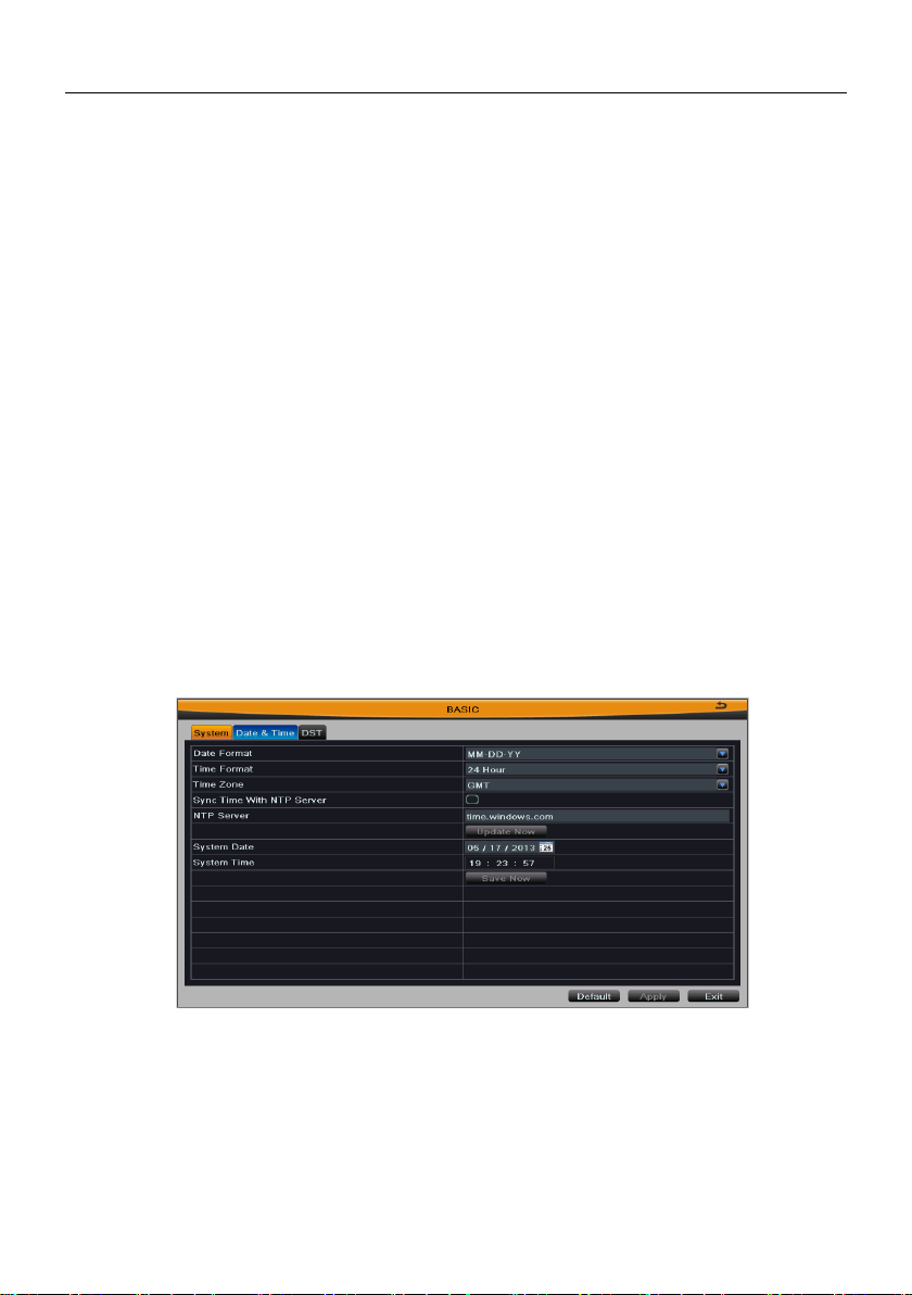
4.2.2 Date & Time
Enter into Main MenuSetupBasicDate & Time; refer to Fig 4-5:
User can set the date format, time format and time zone; enable “Sync Time with NTP
Server” and click “Update Now” button to synchronize device time with NTP server
(optional); or manually set the device time and click “Save Now” button.
Fig 4-5 basic configuration-date & time
Note: Time zone is GMT by default; please select your local time zone in the
drop-down box, such as GMT+8:00.
Click “Default” button to restore the default setting; click “Apply” button to save the
setting; click “Exit” button to exit current menu.
9
Page 25
Digital Video Recorder User Manual
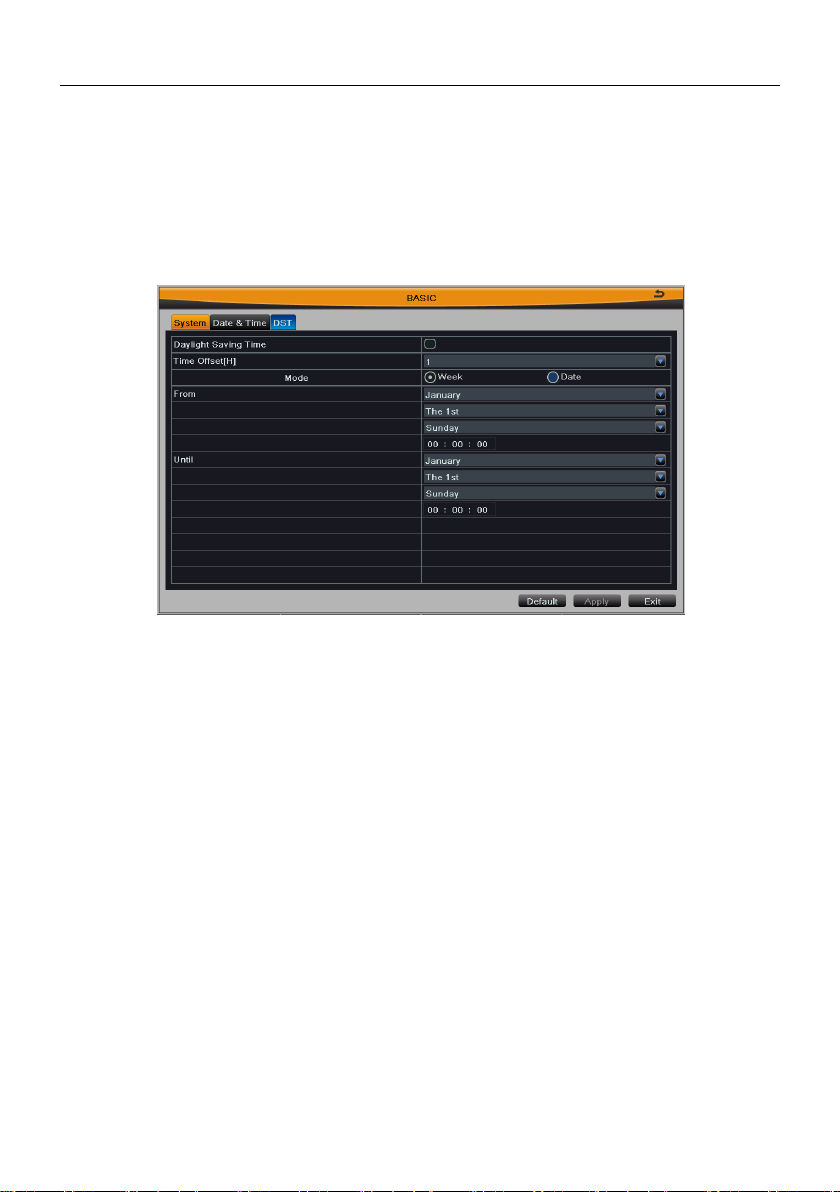
4.2.3 DST
Enter into Main MenuSetupBasicDST; refer to Fig 4-6:
Enable “Daylight Saving Time”, and set time offset, mode, start & end time.
Click “Default” button to restore the default setting; click “Apply” button to save the
setting; click “Exit” button to exit current interface.
Fig 4-6 basic configuration-DST
4.3 Live Configuration
Live configuration includes three submenus: live, main monitor and mask.
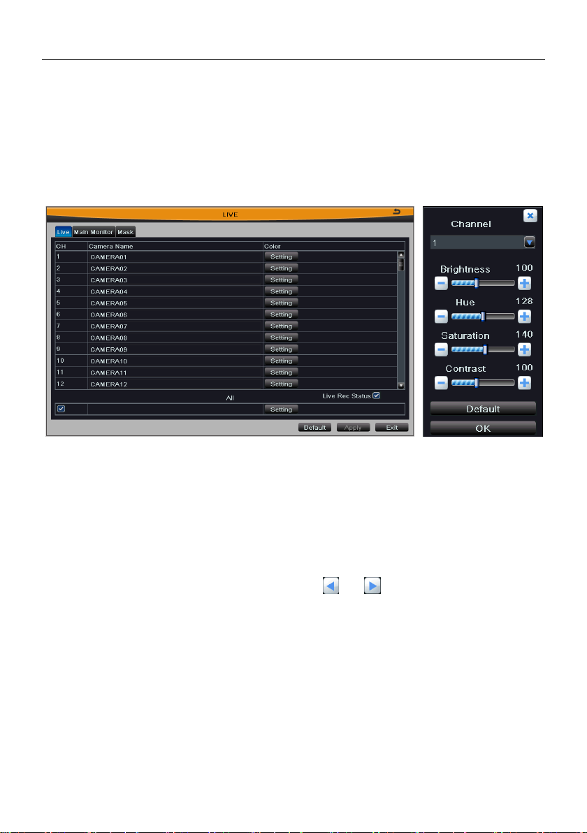
4.3.1 Live
Enter into Main MenuSetupLiveLive; refer to Fig 4-7:
Camera Name: Click camera name to pop up a soft keyboard, click Shift button to
switch the input state, user can self-define the channel name.
Color: Click “Setting” button to display a window as Fig 4-8. User can adjust the
brightness, hue, saturation and contrast of channel video, click “default” button to
resort default setting; click “OK” button to save the setting.
10
Page 26
Digital Video Recorder User Manual
All: Select “all” and then do relevant setup, user can set all channels with same
parameters.
Live Rec Status: In upper left corner of the screen will appear a status icon when
manual or triggered recording is active.
Click “Default” button to restore the default setting; click “Apply” button to save the
setting; click “Exit” button to exit current interface.
Fig 4-7 live configuration-live Fig 4-8 live-color adjustment
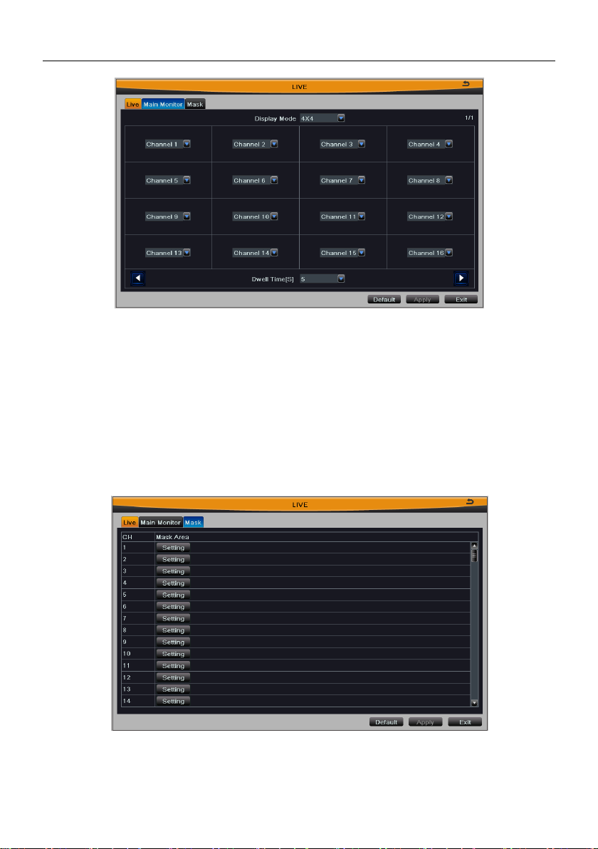
4.3.2 Main Monitor
Enter into Main MenuSetupLiveMain Monitor; refer to Fig 4-9:
Select the display mode (synchronize with configured device); set the channel
combination of current picture group, click or button to set the previous/
latter channel groups of dwell picture; set dwell time: the time interval for a certain
dwell picture display switching to next dwell picture display.
11
Page 27
Digital Video Recorder User Manual
Fig 4-9 live configuration-main monitor
Click “Default” button to restore the default setting; click “Apply” button to save the
setting; click “Exit” button to exit current menu.
4.3.3 Mask
Enter into Main MenuSetupLiveMask, user can set private mask area on the
live image, refer to Fig 4-10:
Fig 4-10 live configuration-mask
Set mask area: Click “Setting” button, then click and drag cursor to set the privacy
12
Page 28
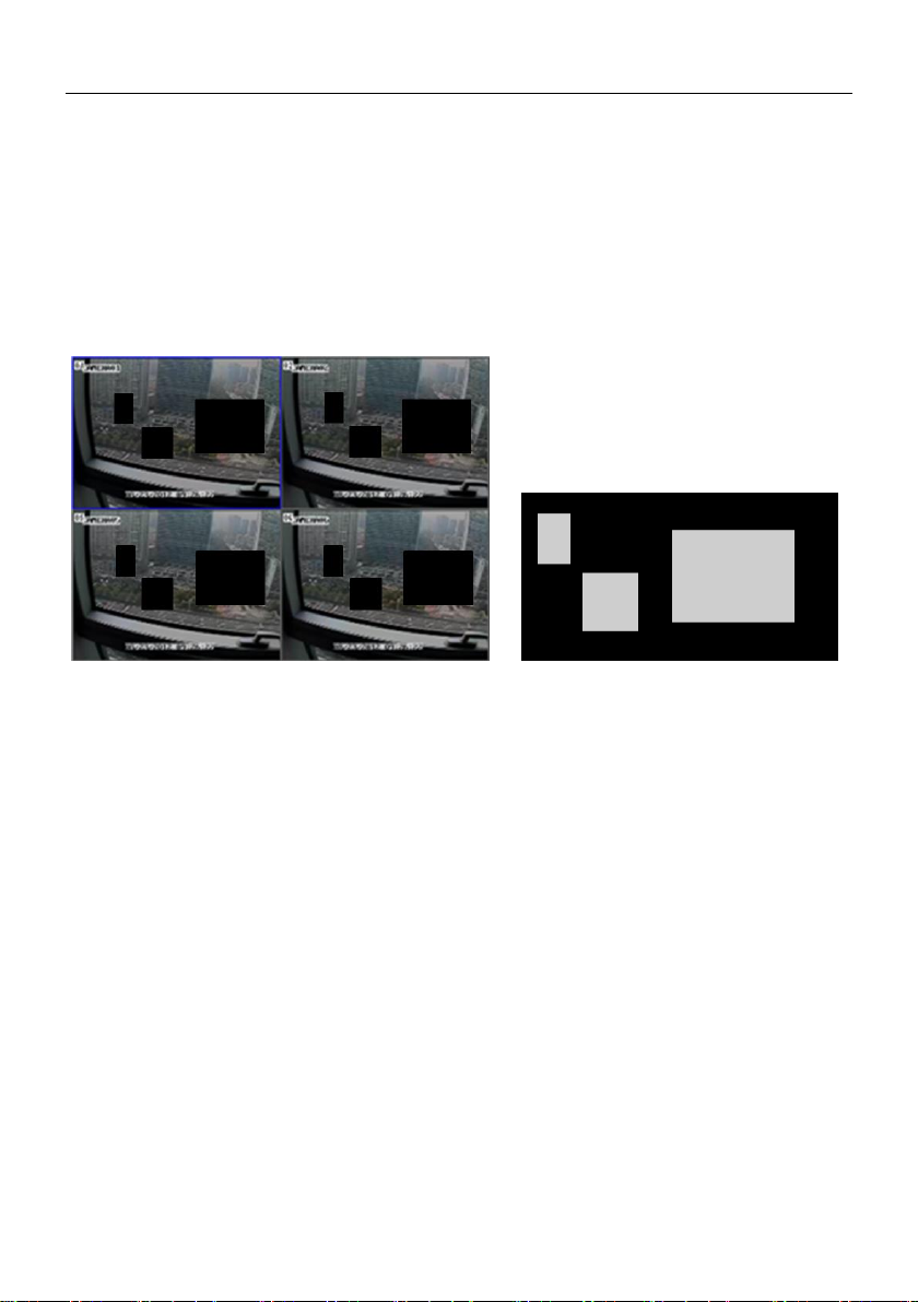
Digital Video Recorder User Manual
area of video image. An image can be entirely or partially masked, it supports 4 areas
maximum. Click right mouse to return to the previous interface. Refer to Fig 4-10(a)
and Fig 4-10(b):
Delete mask area: Select a certain mask area, double click left mouse to delete that
area, click right mouse to return to previous menu.
Click “Default” button to restore the default setting; click “Apply” button to save the
setting; click “Exit” button to exit current menu.
Fig 4-10(a) Setup mask area Fig 4-10(b) live image mask area
4.4 Record Configuration
Record configuration includes six submenus: enable, record bitrate, time, stamp
recycle record and snap.
4.4.1 Enable
Enter into Main MenuSetuprecordenable; refer to Fig 4-11:
Select “Record” and “Audio” to open the record and audio of every channel.
Select “all” to set all channels with same parameters.
Click “Default” button to restore the default setting; click “Apply” button to save the
setting; click “Exit” button to exit current interface.
13
Page 29
Digital Video Recorder User Manual
Fig 4-11 record configuration-enable
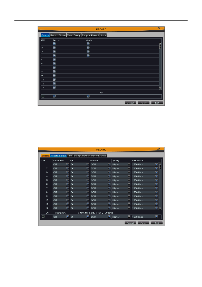
4.4.2 Record Bitrate
Enter into Main MenuSetuprecordrecord bitrate; refer to Fig 4-12:
Fig 4-12 record configuration-record bitrate
Set the resolution, frame rate, encode, quality and max bitrate.
Select “all” and then do relevant setup, user can set all channels with same
parameters.
Click “Default” button to restore the default setting; click “Apply” button to save the
14
Page 30
Digital Video Recorder User Manual
Parameter
Meaning
Resolution
The range of options: synchronize with configured device, such as CIF
Fps
Range from 1~30(NTSC)or 1~25(PAL)
(Resolution and frame rate are determined by the parameter
specifications of specific type)
Encode
Two options: VBR and CBR
Quality
The higher the grade is, the clearer the recorded image is. Six grades:
lowest, lower, low, medium, higher and highest.
Max Bitrate
The range of options: synchronize with configured device, such as
256~2048kbps
setting; click “Exit” button to exit current menu.
Note: If frame rate surpasses the maximum resources of device, the value will
be adjusted automatically.
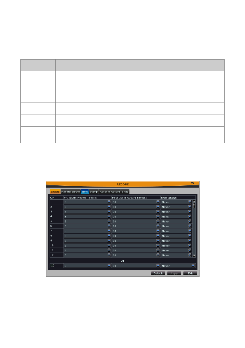
4.4.3 Time
Enter into Main MenuSetupRecordTime; refer to Fig 4-13:
Fig 4-13 record configuration-time
Pre-alarm Record Time: Alarm signal needs a little time to process and trigger
recording, it may not record some important information before alarm activation. This
function can save pre-recording and improve monitoring reliability. Set the record time
before event happen (motion detection or sensor alarm).
15
Page 31

Digital Video Recorder User Manual
Post-alarm Record Time: Set the delay time to stop the record after the alarm is
finished.
Expire [Days]: The hold time of recorded files. If the recorded files are overdue, they
will be deleted automatically.
Select “all” and then do relevant setup, user can set all channels with same
parameters.
Click “Default” button to restore the default setting; click “Apply” button to save the
setting; click “Exit” button to exit current interface.
4.4.4 Stamp
Enter into Main MenuSetuprecordstamp; refer to Fig 4-14:
Select Camera Name, Time Stamp to overlap the camera name and time stamp on
video.
Click “Setting” button, then drag the camera name and time stamp in random position.
Please refer to below Fig 4-14(a) and Fig 4-14(b):
Select “all” and then do relevant setup, user can set all channels with same
parameters.
Select “Default” button to restore the default setting; click “Apply” button to save the
setting; click “Exit” button to exit current menu.
16
Page 32

Digital Video Recorder User Manual
Fig 4-14(a) Before drag Fig 4-14(b) After drag
4.4.5 Recycle Record
Enter into Main MenuSetupRecordRecycle record.
When the storage space is full, “Recycle Record” will cover the earliest storage files
and keep recording, otherwise it will stop recording and generate an alarm
automatically.
Select “Default” button to restore the default setting; click “Apply” button to save the
setting; click “Exit” button to exit current menu.
Note: The space size of recorded files is mainly determined by the image
quality, frame rate and resolution, the higher their parameter settings, the
greater the disk space required.
4.4.6 Snap
Enter into Main MenuSetupRecordSnap.
In this interface, user can set up the resolution, quality, snap time interval and snap
number of snap pictures.
Click “Default” button to restore the default setting; click “Apply” button to save the
setting; click “Exit” button to exit current menu.
17
Page 33

Digital Video Recorder User Manual
4.5 Schedule Configuration
Enter into Main MenuSetupSchedule. Schedule configuration includes four
submenus: schedule, motion, sensor and reboot the system; refer to Fig 4-15:
4.5.1 Schedule
Fig 4-15 schedule configuration-schedule
The column means the seven days of a week from Monday to Sunday; the row means
24 hours of a day.
Step 1: Select channel;
Step 2: Click button, then click and drag cursor to add recording time in the grid
area; click button, then click and drag cursor to delete recording time. Blue
means selected area, black means unselected area.
Step 3: Double-click the grid area and a dialog box will pop-up; user can edit week
schedule of recording, refer to Fig 4-16:
Select a week day; click “Add” button, then set the start & end time of recording plan,
click to add a certain day schedule; select a plan in the week schedule list, click
“Delete” button to delete the selected plan.
You can copy and apply time settings to the other date or every day. Click “Copy”
18
Page 34

Digital Video Recorder User Manual
button to copy the specified day schedule to other dates.
Click “OK” button to save the setting, click “Exit” button to exit current interface.
Fig 4-16 schedule configuration-week schedule
Step 4: User can copy and apply channel settings to the other channel or all channels.
Click “Copy” button to copy the specified channel schedule to other channel.
Step 5: Click “Default” button to restore the default setting; click “Apply” button to
save the setting; click “Exit” button to exit current menu.
19
Page 35

Digital Video Recorder User Manual
4.5.2 Motion
The interface of motion detection configure is shown in Fig 4-17:
Fig 4-17 schedule configuration-motion
The setup steps of motion are similar to the schedule; user can refer to 4.5.1 schedule
for details.
Note: The default schedule of motion detection is full-selected, that is, the color
of schedule setting interface is blue.
4.5.3 Sensor
The interface of sensor alarm configure is shown in Fig 4-18:
20
Page 36

Digital Video Recorder User Manual
Fig 4-18 schedule configuration-sensor
The setup steps of sensor are similar to the schedule; user can refer to 4.5.1 schedule
for details.
Note: The default schedule of sensor alarm is full-selected, that is, the color of
schedule setting interface is blue.
4.5.4 Reboot the System
The interface of timing reboot configure is shown in Fig 4-19. User can open the
timing reboot function of device, set reboot date and time, it supports 3 time
configurations.
Fig 4-19 schedule configuration-reboot the system
21
Page 37

Digital Video Recorder User Manual
4.6 Alarm Configuration
Enter into Main MenuSetupAlarm. Alarm configuration includes five submenus:
sensor, motion, video loss, other alarm and alarm out.
4.6.1 Sensor
Sensor includes three submenus: basic, alarm handling and schedule.
1. Basic
Refer to Fig 4-20. User can enable sensor alarm of alarm input; select the alarm type
according to alarm trigger type: N.O. (normally open) and N.C. (normally closed).
Fig 4-20 alarm configuration-sensor-basic
Select “all” and then do relevant setup, user can set all channels with same
parameters.
Click “Default” button to restore the default setting; click “Apply” button to save the
setting; click “Exit” button to exit current menu.
2. Alarm Handling
Refer to Fig 4-21. Select the holding time of sensor alarm; click “Setting” button to pop
up a window, refer to Fig 4-22:
22
Page 38

Digital Video Recorder User Manual
Fig 4-21 alarm configuration-sensor-alarm handling
Fig 4-22 alarm handling-trigger
Buzzer: After selecting Buzzer alarm, there will be buzzing when alarm is triggered.
Show Full Screen: Pop up full screen of channel video (optional) when alarm is
triggered.
To Alarm Out: Linkage specified alarm output with built-in relay when alarm is
triggered.
Email: Enable this function, the information of sensor alarm will be sent to mailbox.
The notification email can contain text messages and images.
23
Page 39

Digital Video Recorder User Manual
To Snap: Links the specified channel to capture the image when alarm is triggered. If
user enables the Email function, these pictures will be sent to user’s designed email
box.
To Record: Links the specified channel to record video when alarm is triggered.
To P.T.Z: Sets the preset PTZ position when alarm is triggered: number, preset, cruise
and track; refer to Fig 4-23. Click OK button to save the setting; click Exit button to exit
the current menu.
Fig 4-23 alarm handling-to PTZ
Select “all” and then do relevant setup, user can set all channels with same
parameters.
Click “Default” button to restore the default setting; click “Apply” button to save the
setting; click “Exit” button to exit current menu.
3. Schedule
The detecting schedule of sensor alarm is shown in Fig 4-24.
The setup steps of detecting schedule are similar to the schedule; user can refer to
4.5.1 for details.
Note: The default schedule of sensor alarm is full-selected, that is, the color of
schedule setting interface is blue.
24
Page 40

Digital Video Recorder User Manual
Fig 4-24 alarm configuration-sensor-schedule
4.6.2 Motion
Motion includes two submenus: motion and schedule.
Motion
The interface of motion detection configure is shown in Fig 4-25.
Fig 4-25 motion-configuration
Step 1: Enable motion detection alarm; select the alarm holding time.
Step 2: Click “Setting” button of motion trigger to pop up a window, as shown in Fig
25
Page 41

Digital Video Recorder User Manual
4-26. The setup steps of motion trigger are similar to the sensor alarm handling; user
can refer to Chapter 4.6.1 SensorAlarm handling for more details.
Step 3: Click “Setting” button of motion area to pop up a window, as shown in Fig
4-27:
Fig 4-26 motion-trigger setting Fig 4-27 motion-area setting
Due to the sensitivity is influenced by color and time (day or night); user can drag
slider to adjust the sensitivity of motion detection (1-8) according to the practical
situation.
Click button to set the whole area as detection area; click button to clear
detection area; click button to test whether the sensitivity and motion area are
suitable; click button to save the setting; click button to exit current
interface.
Step 4: Select “all” and then do relevant setup, user can set all channels with same
parameters.
Step 5: Click “Default” button to restore the default setting; click “Apply” button to
save the setting; click “Exit” button to exit current menu.
① Schedule
The schedule of motion detection is shown in Fig 4-28.
The setup steps of motion detection schedule are similar to schedule; user can refer
to 4.5.1 Schedule for details.
Note: The default schedule of sensor alarm is full-selected, that is, the color of
schedule setting interface is blue.
26
Page 42

Digital Video Recorder User Manual
Fig 4-28 motion-schedule
4.6.3 Video Loss
The interface of video loss configure is shown in Fig 4-29. Click “Trigger” button to
pop up a window, as shown in Fig 4-30, the setup steps of trigger are familiar with
sensor alarm handling; user can refer to Chapter 4.6.1 SensorAlarm handling for
more details.
Fig 4-29 alarm configuration-video loss
27
Page 43

Digital Video Recorder User Manual
Fig 4-30 video loss-trigger
4.6.4 Other Alarm
Step 1: Refer to Fig 4-31, select the alarm type, set the trigger options. When the
selected alarm is triggered, it will trigger the relevant alarm.
Fig4-31 alarm configuration-other alarm
Select “Disk Full”: set a threshold value for remaining HDD space. If the threshold
value is reached, the system will display a prompt.
Select “IP Conflict”: when IP address conflicts with other network device’s IP address
on the same segment, the system will trigger alarm prompt if you have set the trigger
options.
Select “Disconnect”: the system will trigger alarm prompt if you have set the
trigger options when disconnected from the network.
Select “Disk Attenuation Warning”: trigger the relevant alarm when HDD is bad.
Select “Disk Lost”: trigger the relevant alarm when HDD dropped off.
28
Page 44

Digital Video Recorder User Manual
Step 2: Click “Default” button to restore the default setting; click “Apply” button to
save the setting; click “Exit” button to exit current menu.
4.6.5 Alarm Out
Alarm out includes three submenus: alarm out, schedule and buzzer.
1. Alarm out
Refer to Fig 4-32, user can self-define relay name and select holding time of alarm out.
Check “all” to set all channels with same parameters.
Click “Default” button to restore the default setting; click “Apply” button to save the
setting; click “Exit” button to exit current menu.
Fig4-32 alarm configuration-alarm out schedule
The detecting schedule of alarm out is shown in Fig 4-33.
The setup steps of alarm out schedule are similar to the schedule; user can refer to
4.5.1 Schedule for details.
Note: The default schedule of alarm out is full-selected, that is, the color of
schedule setting interface is blue.
29
Page 45

Digital Video Recorder User Manual
Fig4-33 alarm configuration-schedule
Select “Buzzer” to turn on the switch of alarm sound, set buzzer alarm hold time. It will
trigger the sound alarm when alarm is triggered.
4.7 Network Configuration
Enter into Main MenuSetupNetwork. Network configuration includes five
submenus: network, sub-stream, Email, WIFI setup and other settings.
4.7.1 Network
Refer to Fig4-34; user can set the device’s HTTP port and server port. If DHCP
function of router is enabled, selecting “Obtain an IP address automatically” will
automatically obtain IP address, subnet mask and gateway from the router.
Using DDNS function outside this area needs to set the address of DNS server as
their local DNS address. Enable PPPoE dial-up function, user needs to enter the user
name and password of ADSL dial-up obtained from the internet service provider. Click
“Test” button to test the effectiveness of the relevant information.
30
Page 46

Digital Video Recorder User Manual
Fig 4-34 network configuration-network
Note: You may want to use a different port than the default HTTP port 80. If so,
you need to configure your DVR to use the port you want. After configured,
remember that you have to specify its port number in the URL (e.g. if you select
port 88, you access it using http://192.168.1.10:88).
Click “Default” button to restore the default setting; click “Apply” button to save the
setting; click “Exit” button to exit current interface.
4.7.2 Sub-stream
The interface of network sub-stream configure is shown in Fig 4-35. Select the
sub-stream parameters of each channel according to the following table.
Tick off “all” and then do relevant setup, user can set all channels with same
parameters.
Click “Default” button to restore the default setting; click “Apply” button to save the
setting; click “Exit” button to exit current interface.
Note: When you select resolution and fps, the system will display free CIF
frame rate.
31
Page 47

Digital Video Recorder User Manual
Parameter
Meaning
Resolution
The range of options: synchronize with configured device,
such as QCIF
Fps
The range of options: synchronize with configured device.
(Resolution and frame rate are determined by the
parameter specifications of specific type)
Encode
Two options: VBR and CBR
Quality
The higher the grade is, the clearer the recorded image
is. Six grades: lowest, lower, low, medium, higher and
highest.
Max Bitrate
The range of options: synchronize with configured device,
such as 32~768kbps
Fig 4-35 network configuration-sub-stream
32
Page 48

Digital Video Recorder User Manual
4.7.3 Email
The interface of email configure is shown in Fig 4-36.
Fig 4-36 network configuration-email
SMTP Server: Outgoing Mail Server Address. Mail server addresses are different for
different Email service providers, e.g. the SMTP server of 163 mailbox is
smtp.163.com, and the SMTP server of Gmail mailbox is smtp.gmail.com.
Port: Port number of SMTP server, usually is 25, or it may be 587, 993 or 465, etc.
SSL Check: Enable mail encryption function.
Send Address/Password: Sender’s email address/password.
Receive Address: Receiver’s email address. Here user can add three mail
addresses at most. Click “Test” button to test the validity of the mailbox.
Click “Default” button to restore the default setting; click “Apply” button to save the
setting; click “Exit” button to exit current menu.
33
Page 49

Digital Video Recorder User Manual
4.7.4 WIFI Setup
The interface of WIFI configure is shown in Fig 4-37. User can enable WIFI function,
click “Search Signal” button to automatically search router, and the router’s
information are displayed in the list. Select a router, enter the password and click OK
button. With a successful connection to the router, we can set up a wireless IP.
Click “Default” button to restore the default setting; click “Apply” button to save the
setting; click “Exit” button to exit current menu.
Fig 4-37 network configuration-WIFI setup
4.7.5 Other Settings
Bind the device with a fixed domain name, so that user can visit the device no matter
how the public IP changes. Enable DDNS function, select the DDNS server and
update interval, enter the user name, password and host domain name registered in
DDNS server, such as MyDVR.no-ip.org. Click “Test” button to test the effectiveness
of the relevant information; refer to Fig 4-38:
34
Page 50

Digital Video Recorder User Manual
Fig 4-38 network configuration-other settings
Enabling UPNP function can automatically map the port currently in use to router.
Click “Default” button to restore the default setting; click “Apply” button to save the
setting; click “Exit” button to exit current menu.
Note: The domain name server that selected by user is a banding domain name
of DVR. User should logon the website which provided by the server supplier to
register a user name and password firstly, and then apply a domain name on
line for the server. After the successful apply, user can access the server from
the IE client by inputting that domain name.
Enable UPnP: User may select UPnP and then enable UPnP function in the user’s
router. You can access DVR through WAN. When accessing the DVR through IE,
user can check the IP address by the following method: Double-click the “My Network
Places” icon on the desktop in PC, select “Show icons for networked UPnP devices”
in the “Network Tasks” list box, a information window will pop up, click “YES” button,
“Windows Components Wizard” dialog box will pop up as shown as below pic ture,
press “Next” to continue. After finished the installation of configuring components, the
UPnP icons will display. Users can double-click it and check the IP address of the
device.
35
Page 51

Digital Video Recorder User Manual
If “Show icons for networked UPnP devices” can’t display in the “Network Tasks” list
box, please operate as follows:
Click “Tools”-- “Folder options”
Select the “Show common tasks in folders” in the “Tasks” check box to
display the UPnP icon.
1. Domain Name Registration (Take www.no-ip.com for example)
Open the web browser (Internet Explorer by default) and enter http://www.no-ip.com
in the address bar.
Step 1: Create an account
Click the “Sign-up for an Account” link at drop-down menu of “Sign In”.
Select the type of registration according to the features introduced. In this paper, we
take “FREE DNS” for example. Click “SIGN UP>” button below the “FREE DNS”.
Fill in the required fields on the new account form.
Once you've filled in the required information and agreed to Terms of Service, click
“Sign Up” button at the bottom of the page.
36
Page 52

Digital Video Recorder User Manual
Note: Terms of Service requires valid contact information on file in order to
maintain your account. Any accounts found with incomplete or fraudulent
information will be terminated.
Step 2: Confirm your account
Once you have submitted your account information into the new user form, it will send
a confirmation email to the address you provided. You will need to check that account
and look for the email from No-IP.com. The email contains a link you must click in
order to confirm your account.
So please click the URL link to activate your account in the confirmation email, and
then automatically enter the “Account Confirmed!” interface.
Step 3: Login to your account
Select “Sign In” on the top of No-IP home page to pop up drop-down menu, or click
“Sign In” button to enter “Client Login” interface. Enter email address and password
that you signed up and click Login button. As shown below:
Step 4: Add a host or domain to your account
37
Page 53

Digital Video Recorder User Manual
In order to add a host to your account, select the "Add" link from the "Hosts/Redirects"
menu. This will bring up the Add a Host page. And now you're ready to fill in the
details of your new hostname.
Note: For more detailed guide of No-ip service, please visit
http://support.no-ip.com/
2. Enable DDNS on the DVR
Enter into Main MenuSetupNetworkOther settings.
38
Page 54

Digital Video Recorder User Manual
DDNS: Select ON/OFF
DDNS type: choose www.no-ip.com;
User Name: the account you created at no-ip.com;
Password: the password of your account at no-ip.com.
Host Domain: enter the host name you created at no-ip.com;
DDNS Update: Choose the DDNS update period.
Click Apply button to save the setting.
Enter into configuration interface of the router to map the server port and IP address
(if the user enables UPnP function of device and router, he can skip this step).
Note: Please allow 10~15 minutes for the DDNS service to update with your new
DDNS address. This is normal for the DDNS system.
3. Accessing your DVR remotely
Open Internet Explorer and enter the host name (e.g. http://MyDVR.no-ip.org ) in the
address bar to access it.
39
Page 55

Digital Video Recorder User Manual
4.8 User Management Configuration
Enter into Main MenuSetupUsers; refer to Fig 4-39. Click “Add” button to pop up
a window, as shown in Fig 4-40:
Fig 4-39 user management configuration
Fig 4-40 add-general
① General: Enter the new user's name and password; select user type: normal and
advance; or tick off “Binding PC Mac Address”, input the MAC address of the PC as
required; click OK button to add this user into the user list; click Exit button to exit the
current interface.
40
Page 56

Digital Video Recorder User Manual
Note: When the value of binding PC MAC address is 0, user is not binding with
the specified computer; if you set the binding Mac address for the user, only
the PC with this Mac address can visit the device through network.
Authority: Refer to Fig 4-41, assign the appropriate privileges for that user, click OK
button to save the setting; click Exit button to exit the current menu.
Fig 4-41 add user-authority
In the user management interface, select a user in the user list, click “Setup” button
to modify user type, binding PC MAC address and user authority. Select a user in the
user list, click “Delete” button to delete this user. Select a user and click “Change
Password” button to modify the password of this user. Click Exit button to exit the
current interface.
Note: The administrator cannot be modified and deleted. User can only modify
their password.
41
Page 57

Digital Video Recorder User Manual
4.9 P.T.Z Configuration
Enter into Main MenuSetupPTZ. P.T.Z configuration includes two submenus:
serial port and advanced.
4.9.1 Serial Port
Refer to Fig 4-42, enable P.T.Z control of any channel; select the correct PTZ settings
according to the external communication device, the meaning of PTZ parameters is
shown in the table below. Select “all” and then do relevant setup, user can set all
channels with same parameters.
Fig 4-42 P.T.Z configuration-serial port
Click “Default” button to restore the default setting; click “Apply” button to save the
setting; click “Exit” button to exit current menu.
42
Page 58

Digital Video Recorder User Manual
Parameter
Meaning
Address
Address of the PTZ device
Baud rate
Baud rate of the PTZ device; synchronize with
configured device
Protocol
Communication protocol of the PTZ device;
synchronize with configured device
Simulative
Cruise
If enabled, whether the PTZ device supports or not,
the presets will cruise
4.9.2 Advanced
The interface of P.T.Z advanced configure is shown in Fig 4-43:
Fig 4-43 P.T.Z configuration-advanced
Preset
1) Click “Setting” button of preset to pop up a window, as shown in Fig 4-44. User can
enable the preset function, self-define the preset name, and click “Setting” button to
pop up the preset interface, as shown in Fig 4-45.
43
Page 59

Digital Video Recorder User Manual
Fig 4-44 advanced-preset setting
Fig 4-45 preset
2) Select a channel or all channels which need to configure PTZ parameters; control
the dome rotates up, up left, left, left down, down, right down, right, up right and stop
rotating; drag the slider to adjust the rotate speed; zoom, focus and iris are adjustable;
select the serial number of preset point, which allows up to 128 presets to be included,
then click “Save” button to save the preset position; click button to enable the
PTZ wiper, click button to enable the PTZ light.
Note: Wiper and light buttons can take effect with support from PTZ function. At
the same time these two buttons are just available when selecting PELCOP or
PELCOD.
3) Click button to hide the tool bar, click the right mouse button to revert back;
click button to exit the current menu.
4) In the preset setting menu, click OK button to save the setting; click Exit button to
exit current menu.
44
Page 60

Digital Video Recorder User Manual
Cruise
1) Click “Setting” button of cruise in Fig 4-43, then click “Add” button to add cruise line
in the list (8 cruise lines can be added at most), as shown in Fig 4-46.
Fig 4-46 advanced-cruise setting
2) Select a cruise line and click “Setup” button, refer to Fig 4-47.
Fig 4-47 cruise setting-modify
3) Click add button, choose which preset to use, and set its speed and time, then
click button to add this preset point; select a preset point and click delete
button to delete it; select a preset point and click set button to modify the settings.
45
Page 61

Digital Video Recorder User Manual
User can click button to adjust the order of selected preset.
4) Click “Preview” button to preview the selected cruise line, click OK button to save
the setting, click Exit button to exit current menu.
5) Select a cruise line in the list, click “Delete” button to delete it; click “Clear All”
button to clear all cruise lines; click OK button to save the setting; click Exit button to
exit current menu.
Track
1) Click “Setting” button of track in Fig 4-43 to pop up a window, as shown in Fig 4-48.
Fig 4-48 advanced-track setting
2) Select a channel or all channels which need to configure PTZ parameters; control
the dome rotates up, up left, left, left down, down, right down, right, up right and stop
rotating; drag the slider to adjust the rotate speed; zoom, focus and iris are adjustable;
click button to enable the PTZ wiper, click button to enable the PTZ light.
Note: Wiper and light buttons can take effect with support from PTZ function. At
the same time these two buttons are just available when selecting PELCOP or
PELCOD.
3) Click “Start Record” button to record the track of PTZ movements, click this button
again to stop recording; click “Start Track” button to play recorded track, click this
button again to stop playing.
4) Click button to hide the tool bar, click the right mouse button to revert back;
click button to exit the current menu.
In the advanced interface, click “Default” button to restore the default setting; click
“Apply” button to save the setting; click “Exit” button to exit current menu.
46
Page 62

Digital Video Recorder User Manual
4.10 Advanced Configuration
Enter into Main MenuSetupAdvanced. Advanced configuration includes two
submenus: reset and import/export.
4.10.1 Reset
Click “Reset” button to pop up a warning window, then click OK button to restore
factory settings and restart the device automatically, click Cancel button to exit the warning
window.
4.10.2 Import/Export
User can export the data files into mobile storage device as backup function, or import
specified data files from mobile storage device to DVR.
47
Page 63

Digital Video Recorder User Manual
Chapter 5 Manage DVR
5.1 Search and Playback
Search configuration includes four submenus: time search, event search, file
management and image.
5.1.1 Time Search
Step 1: Enter into Main MenuSearchTime Search; refer to Fig 5-1:
Fig 5-1 Search configuration-time search
Step 2: Select the channels which need to search data, set screen display mode;
select a date, the highlight date in the calendar means have record data.
Step 3: Press Search button, the searched record information will be displayed in the
timeline panel. The blue grid means have record. Click the time grid to set the
playback start time or input this time manually.
Note: The vertical column means hours, the horizontal column means
channels.
Note: When the resolution of monitor is VGA800*600, the time search interface
48
Page 64

Digital Video Recorder User Manual
(1) play/pause
(2) stop
(3) next frame
(4) fast forward/ rewind
(5) screen mode
(6) clip backup
(7) volume
(8) hide toolbar
(9) exit
(10) move tool
(11) last segment of
record
(12) next segment of
record
will show a hide button, click it to expand the whole interface.
Step 4: Click Play button to playback record from the selected time; click the
relevant buttons on the screen to do operation. The range of options synchronizes with
configured device; refer to Fig 5-2:
Fig 5-1 Playback buttons
5.1.2 Event Search
Step 1: Enter into Main MenuSearchEvent Search; refer to Fig 5-3:
Fig 5-3 Search configuration-event search
49
Page 65

Digital Video Recorder User Manual
Step 2: Select the channels which need to search data, set event type (motion,
sensor); select a date, the highlight date in the calendar means have record data.
Step 3: Press Search button, the searched event information will be displayed in the
event list. Double click an event file to playback. Click the relevant buttons on the
screen to do operation.
Note: When the resolution of monitor is VGA800*600, the time search menu will
show a hide button, click it to expand the whole interface.
5.1.3 File Management
Step 1: Enter into Main MenuSearch File Management; refer to Fig 5-4:
Fig 5-4 Search configuration-file management
Step 2: Select the channels which need to search data; select a date, the highlighted
dates in the calendar means you have recorded data.
Step 3: Press Search button, the searched file information will be displayed in the file
list.
Lock: Select a file and click “Lock” button, then click OK button in the pop-up
message box to lock this file, after that, that file will not be deleted or covered.
Note: Once the file is locked, it will not be hidden or deleted, but format will
clear the locked file.
Unlock: Select a locked file and click “Lock” button again, then click OK button in the
50
Page 66

Digital Video Recorder User Manual
pop-up message box to unlock this file.
Delete: Select an unlocked file and click “Delete” button, then click OK button in the
pop-up message box to delete this file.
Tick off “All”, user can lock/unlock or delete all files.
Step 4: Double click a file to playback. Use the control buttons to change the
playback operation.
Note: When the resolution of monitor is VGA800*600, the time search interface
will show a hide button, click it to expand the whole interface.
5.1.4 Image
Step 1: Enter into Main MenuSearchImage; refer to Fig 5-5:
Fig 5-5 Search configuration-image
Step 2: Select the channels which need to search data and the start & end time.
Step 3: Press Search button, the searched image will be displayed in the picture box.
Click button to browse images. There are at most 2000 images
saved in the SATA disk. If exceed 2000 images, it will cover the earliest storage
images.
Lock: Select an image, click “Lock” button to lock this image, after that, that image
will not be deleted or covered, but format will clear the locked images.
Unlock: Select a locked image, click “Lock” button again to unlock this image.
51
Page 67

Digital Video Recorder User Manual
Delete: Select an unlocked image, click “Delete” button to delete this image.
Save / Save All: Save the current image / all images to the USB disk and other
removable storage devices.
Step 4: Double click the image to playback recordings from when it was captured.
5.2 Backup
This unit supports backup DVR data files by USB disk through the USB port. User can
also remotely backup data by IE browser via internet.
Step 1: Insert a USB disk on the DVR. Enter into Main MenuBackup; refer to Fig
5-6:
Fig 5-6 backup configuration
Step 2: Select the channels which need to backup data and the start & end time.
Press Search button, the searched data will be displayed in the data backup list.
Step 3: Select any data file or tick off “All” to select all data files, click “Backup” button
to pop up the backup information dialog box.
Step 4: Check the information of backup files, including storage type, save file type,
etc. Click “Start” button to start backup.
Note: When the resolution of monitor is VGA800*600, the data backup interface
will appear a hide button, click it to expand the whole interface.
52
Page 68

Digital Video Recorder User Manual
5.3 Information
User can check the device information, including system, event, log, network and
online users.
5.3.1 System Information
Enter into Main MenuInformationSystem. In this interface, user can check the
device name, firmware version, launch date, etc.
5.3.2 Event Information
Enter into Main MenuInformationEvent. In this interface, select the channels
which need to check event information and the start & end time, set the event type
(motion, sensor, video loss). Press Search button, the searched event information will
be displayed in the event list. User can check the recorded event information, and
export these informations to a removable storage device if needed.
5.3.3 Log Information
Enter into Main MenuInformationLog. In this interface, select the start & end time
and log type (operation, setup, playback, backup, search, check information, error).
Press Search button, the searched log information will be displayed in the log list.
User can check the recorded log information, and export this information to a
removable storage device if needed.
5.3.4 Network Information
Enter into Main MenuInformationNetwork. In this interface, user can check the
network parameters, including HTTP port, server port, IP address, DDNS server,
status, etc.
53
Page 69

Digital Video Recorder User Manual
5.3.5 Online Users Information
Enter into Main MenuInformationOnline Users. In this interface, check all user
information. Click “Refresh” button to refresh the current online user list. User can
remote view and operate device through IE browser, ISS, CMS.
5.4 Manual Alarm
Enter into Main MenuManual Alarm. Click "Alarm" button to trigger alarm, click
"Clear" button to stop alarm. If user ticks off “Trigger”, it will alarm in accordance with
the setting of alarm out (refer to 4.6.5 Alarm Out); click Exit button to exit the current
interface.
5.5 Disk Management
5.5.1 Format Disk
Please format the hard disk before recording.
Step 1: Enter into Main MenuDisk ManagementDisk.
Step 2: Select a hard disk which needs to format, click “Format” button.
Note: All recorded files (including locked files) in the hard disk will be lost after
formatted.
In the disk management interface, user can modify the property of selected disk; click
“Refresh” button to refresh the disk information. Click "Browse" button to enter the
system information interface, user can see the hard disk’s system information and the
number of saved pictures, click "Clear" button to clear all pictures stored on the hard
disk; click “Apply” button to save the setting.
Note: When clearing all pictures on the hard disk, read-only pictures and locked
pictures cannot be deleted.
54
Page 70

Digital Video Recorder User Manual
5.5.2 Advanced
Enter into Main MenuDisk ManagementAdvanced. User can check the hard disc
model, S/N, firmware, health status and S.M.A.R.T information. S.M.A.R.T function
can monitor the disk’s temperature, internal circuit and dielectric material, analysis the
potential problems and warn so as to protect its data.
5.6 Upgrade
Upgrade steps:
1) Copy the upgrade software into the USB disk, then connect USB disk to the USB
port of DVR.
2) Enter into Main MenuUpgrade. Click "Refresh" button to refresh the list, and the
name of upgrade software is displayed in the upgrade list.
3) Select this name, click “Upgrade” button to start upgrading. Please wait for the
system to restart.
Note: Don't cut off the power in the process of formatting! The device supports
USB update only when the USB is compatible with DVR (refer to Appendix C
Compatible Devices). After the upgrade is complete, restart the system to
activate.
Note: There can only be one upgrade package in USB disk; if no device or file
exists in the upgrade list, it is caused by the incompatible USB disk.
5.7 Logoff
Enter into Main MenuLogoff. Click OK button to log off, click Cancel button to exit
the warning window. To log in again, user needs to enter the user name and password
in the login screen to log in device.
55
Page 71

Digital Video Recorder User Manual
Chapter 6 Remote Surveillance
6.1 IE Remote Surveillance
In order to view the DVR from network, it must be connected to a LAN/WAN or
Internet. The following introduces the connection and use of Internet. Remote access
to the Internet has two types according to their online behavior.
6.1.1 On LAN
Step 1: Right-click "My Network Places" to pop-up a drop-down menu, then click
"Properties" to open the "Network connection".
Step 2: Double-click “Local Area Connection ", then click "Properties" button.
Step 3: Double-click "Internet Protocol (TCP / IP)”.
Step 4: Obtain IP address, subnet mask and gateway of local computer.
Step 5: Set the IP address, subnet mask and gateway of DVR.
Enter into the DVR’s Main MenuSetupNetwork configuration to enter IP address,
subnet mask and gateway. Subnet mask and gateway must be same as the
parameters of “Internet Protocol”, and IP address should be in the same field as your
computer.
E.g. if your computer is 192.168.1.8, then the IP address of DVR can be 192.168.1.X
(“X” is an arbitrary integer between 0 and 255 in addition to 8 and 1), subnet mask is
255.255.255.0, and gateway is 192. 168. 1. 1.
Step 6: After finish the above settings, input the IP address of DVR in browser
address bar to enter the login page, such as: 192.168.1.X. The network will download
control automatically (the settings of browser must allow to download control, refer to
Appendix -1).
Step 7: After the download is complete, interface will pop up a login window.
56
Page 72

Digital Video Recorder User Manual
Step 8: Enter your user name and password. The default username is "admin",
password is blank. Click "OK" to enter into preview interface, as shown below:
IE browser preview
6.1.2 On WAN
There are two ways for the DVR connect to internet.
1. Connect the DVR to internet through ADSL dial-up
Step 1: Enter into the DVR’s Main MenuSetupNetwork configurationNetwork.
Enable PPPoE, and do not set the DVR's network address, subnet mask and gateway,
then fill in the user name and password provided by the telecom operators in, click
Apply button.
57
Page 73

Digital Video Recorder User Manual
Step 2: Enter into the DVR’s Main MenuInformationNetwork information to obtain
IP address, then input it in the browser, such as: http://210.21.229.138, user can enter
the control download interface.
Step 3: The following setup steps are the same as steps 6-8 of Chapter 6.1.1 on LAN.
2. Connect the DVR to internet through router
Step 1: Enter into the DVR’s Main MenuSetupNetwork configurationNetwork to
input IP address, subnet mask and gateway, or tick off "Obtain an IP address
automatically."
Step 2: Make sure the LAN can be connected; access your router by entering the
gateway address, then log on the router management interface to map port.
In this paper, we take Linksys router for example. Specify the IP address and port to
be forwarded from the internal/local IP address of your DVR to the Internet in router
"Port Range Forwarding" of "Applications & Gaming". Each DVR has two ports. (LAN
IP address of DVR can be added to the DMZ host, different router’s configuration is
different, and user can refer to the router manual.)
After mapping the port, user can check the WAN IP address in the “running” of router,
directly access to the DVR through the WAN IP address and HTTP port, such as:
http://113.108.119.20:HTTP port number. Then enter into the control download
interface.
58
Page 74

Digital Video Recorder User Manual
Step 3: The following setup steps are the same as steps 6-8 of Chapter 6.1.1 on LAN.
Owing to WAN address will change frequently, remote access is not very convenient,
and users can access DVR by domain name.
For example: enter into DVR’s Main MenuSetupNetwork configurationOther
Settings, tick off “DDNS”, select DDNS Server, enter the user name, password and
host domain name registered in DDNS server (refer to network configuration), user
can use the domain name to directly access DVR in the WAN access.
6.2 Remote Live Preview
Open the webpage, the first interface is to load the live preview screen. As shown
below:
Remote live preview interface
59
Page 75

Digital Video Recorder User Manual
(1) Channel Indicator
(2) Screen Display Mode
(3) Volume Adjustment
(4) Snap Picture
(5) Client Record: Record current video, and save them in user’s PC.
(6) Local Playback
(7) Remote Manual Recording
(8) Talkback Switch
(9) Color Adjustment
(10) PTZ Control
(11) Channel Status: Display the status of main stream, sub-stream and local video
state.
Buttons
Description
Drag the slider to adjust the brightness of video.
Drag the slider to adjust the hue of video.
Drag the slider to adjust the saturation of video.
6.2.1 Symbol and Function Definition
Channel Indicator:
Green light indicates the manual recording or schedule recording; red light indicates
the sensor alarm recording; yellow light indicates the motion detection recording; blue
light indicates the video loss. Indicators only show the first recording for a single
channel has a variety of recording modes. The priority is as follows: video loss>
sensor alarm > motion-detection > schedule recording= manual recording, 16
indicators represent the 16 channels.
6.2.2 Snap Picture
Click “Snap” button to capture current image, and save it in user’s PC.
Note: User should set up the snap parameters in the Remote Preview
interface CONFIGLocal config.
6.2.3 Color Adjustment
60
Page 76

Digital Video Recorder User Manual
Drag the slider to adjust the contrast of video.
Restore the default values.
Save the adjustment.
Button
Description
Direction keys: control the dome rotates up,
up left, left, left down, down, right down,
right, up right and stop rotating;
Drag the slider to adjust the rotate speed.
'Iris' button. Click button to increase
lighting. Click button to decrease lighting.
'Zoom' button. Click button to zoom in the
live picture of channel. Click button to
zoom out the live picture of channel.
'Focus' button. Click button to lengthen
focal length. Click button to shorten focal
length.
Call preset
Call cruise
Track
Auto scan
6.2.4 PTZ Control
When DVR is connected to PTZ or communication device, user can control it on the
client side. User can control the dome rotates up, up left, left, left down, down, right
down, right, up right and stop rotating; drag the slider to adjust the rotate speed; zoom,
focus and iris are adjustable; call any preset, cruise, track and auto scan.
The function description of remote PTZ operation panel follows below:
61
Page 77

Digital Video Recorder User Manual
6.2.5 Preview Control
Click the right mouse on the live preview interface to pop up a pull-down menu, as
shown below:
Right-click menu
Stream: DVR support dual stream: master stream and sub-stream. Master stream is
HD channel with higher frame rate for every channel, but it needs higher network
bandwidth; Sub-stream is SD channel with low frame rate for every channel, it
requires low network bandwidth.
All to Master/Sub Stream: Set all channels as master stream or sub-stream.
Enable Audio: Enable or disenable the sound of live video.
Full Screen: Display the video in full-screen, and the tool bar will be hided;
double-click left mouse button again or click right mouse button to exit full screen
mode.
Zoom in: Select the magnification to amplify the video. Hold the left mouse button,
and drug the cursor to view the video.
6.3 Remote Playback & Backup
6.3.1 Time Search
Click “SEARCH” button to enter the time search interface, as shown below:
62
Page 78

Digital Video Recorder User Manual
Remote playback interface
Step1: Select the channels which need to search data, set screen display mode;
select a date, the highlight date in the calendar means have record data.
Step2: Press Search button, the searched record information will be displayed in the
data information panel.
Step3: Click Play button to playback record from the selected time.
Step4: Click the relevant button on the screen; user can do some operations such as:
pause, rewind, fast forward, stop, single-frame playback, change channel mode,
research, etc. As shown below:
63
Page 79

Digital Video Recorder User Manual
(1) Play
(2) Pause
(3) Backward / Rewind
(4) Fast Forward
(5) Stop
(6) Next Frame
(7) Previous Section
(8) Next Section
(9) Full Screen
(10) Volume
(11) Process Bar
(12) Channel Mode
(13) Play Mode
(14) Play Button
(15) Snap Picture
(16) Exit
6.3.2 Event Search
Click “Event Search” button to enter the event search interface, as shown below:
64
Page 80

Digital Video Recorder User Manual
Remote Event Search
Step 1: Select the channels which need to search data, set event type (motion,
sensor); select a date, the highlight date in the calendar means have record data.
Step 2: Press Search button, the searched event information will be displayed in the
`event list. Double click an event file to playback. Click the relevant buttons on the
screen to do operation.
6.3.3 File Management
Click “File Management” button to enter the file management interface, as shown
below:
65
Page 81

Digital Video Recorder User Manual
Remote file management
Step 1: Select the channels which need to search data; select a date, the highlight
date in the calendar means have record data.
Step 2: Press Search button, the searched file information will be displayed in the file
list.
Lock: Select any file and click “Lock” button to lock it, after that, that file will not be
deleted or covered.
Unlock: Select any locked file and click “Unlock” button to unlock it
Delete: Select any unlocked file and click “Delete” button to delete it.
Click “All”, user can lock/unlock or delete all files.
Step 3: Double click a file to playback. Click the relevant buttons on the screen to do
operation.
66
Page 82

Digital Video Recorder User Manual
6.3.4 Remote backup
User can backup data by IE browser via internet. Click “BACKUP” button to enter the
backup interface, as shown below:
Remote backup interface
Step 1: Select the start & end time and channels, then click Search button to view
the searched data information in the data list.
Step 2: Select any data file or tick off “All” to select all data files, click “Browse”
button to set the save path, and then click “Backup” button to start backup. The
backup files will be saved on user’s PC.
Note: The backup file is AVI format; they can be played through universal
player.
67
Page 83

Digital Video Recorder User Manual
6.4 Remote Configuration & Management
6.4.1 Remote Configuration
User can configure the device remotely. It not only can set up the network
configuration parameters, but also can set up other parameters through the network.
Click “CONFIG” button to enter the system configuration interface, as shown below.
Remote users can easily set up all the parameters, its options and functions are the
same as the settings of DVR.
Remote menu setup
6.4.2 Remote Management
In the Disk Management interface, user can change the properties of hard disk; check
the hard disk’s information, and format it.
68
Page 84

Digital Video Recorder User Manual
In the Upgrade interface, user can remotely upgrade the device system.
You can also reboot the device.
6.4.3 Remote Check Information
The system records the work status and operating procedure automatically. User can
check the information about system, event, log, network and online users.
Enter into INFOLog; user can set the start & end time and log type, press “Search”
button to search the log records. As shown in the figure below:
Remote Log Search
Note: The log records are saved in the HDD. It will not have any record if HDD
has not been installed. There is no limit on the number of log files, but only with
regard to the storage space of hard disk.
69
Page 85

Digital Video Recorder User Manual
Chapter 7 Mobile Surveillance
You can remotely view Camera streams from your DVR, IPC and IP Dome on your
iPhone™,iPad™, or Android™ device.
Compatible Mobile Viewing Devices
iPhone (4.0 and above)
iPad (4.0 and above)
Android(1.6 and above)
NOTE: Instant Mobile Viewing on an iPhone™ using an iPhone™ App. Free
download available from Apple™ Store under the name “ISSMOBILE”. Compatible
with iPhone™ version 4.0 and above. Selectable 4 channels live viewing. Mobile
phone data plan is required (not included).
Router port forwarding is required.
NOTE: Instant Mobile Viewing on an iPad™ using an iPad™ App. Free download
available from Apple™ Store under the name “ISSMOBILE HD”. Compatible with
iPad™ version 4.0 and above. Selectable 9 channels live viewing. Mobile phone data
plan is required (not included).
Router port forwarding is required.
NOTE: Instant Mobile Viewing on Android™ 1.6 and above. Free download available
from Google™ play store under the name “ISSMOBILE”. Selectable 4 channels live
viewing. Mobile phone data plan is required (not included).
Router port forwarding is required.
Before You Begin:
You will need the following before you can start mobile viewing on your iPhone or
Android device:
The IP address or DDNS host name of your DVR or IP Camera: For details, please
refer to the user manual.
The TCP Port Number of your DVR or IP Camera: By default, the port number is
5000.
User name and Password of your DVR: By default, the ID is admin, no password.
70
Page 86

Digital Video Recorder User Manual
For Android
7.1 Main Functions
Supports Chinese and English;
View the Cameras on real time via Wi-Fi and 3G;
Supports multi-channel switching;
Supports remote play;
Supports device configuration, modification and delete;
Supports photo view and save;
Supports video view and save;
Supports IP and DDNS access;
Supports Pan, Tilt & Zoom control;
Supports Snap-shot;
Supports video records;
Adopt direct connection device, without any third party server.
7.2 Installation
Users can free download this app from Google™ play store on Android™ 1.6 and
above, you may first search “ISSMOBILE”, like Fig 7-1 as below. Router port
forwarding is required.
Then click “Install”, the application will be automatically installed into your mobile
phone, like Fig 7-2 as below:
71
Page 87

Fig 7-1 Fig 7-2
7.3 Application
Digital Video Recorder User Manual
7.3.1 Interface Description
After successfully installed the application into mobile phones, it is ready to run, just
click the ISS MOBILE icon in the main menu. The main interface looks like
Fig 7-3:
Click “ ” icon on top right, then you can access the main menu interface and see
corresponding operation options, including device list, local video, photos, about, etc;
refer to Fig 7-4:
72
Page 88

Digital Video Recorder User Manual
Fig 7-3 Fig 7-4
Device List: Add a new device, or modify the device settings.
Local Video: If ISS MOBILE has record function, after clicking video records, you will
see the details of the records. The name of the record file will be generated by system
default according to recording time.
Video Remote: Access the device recorded clips and view the video.
Saved Photos: Saves a snapshot on the phone when viewing the IP Camera through
the phone; after clicking it, you will see the photos as thumbnail. Enlarge the photos
by clicking it.
Setting: After clicking it, you can set password protection, alarm sound, etc; refer to
Fig 7-5:
About: The related information of the application.
73
Page 89

Digital Video Recorder User Manual
Fig 7-5
7.3.2 Live Preview
Click back key on top left in the main menu interface, back to display interface, refer
to Fig 7-6:
Fig 7-6
Instructions of the functions on “Live Preview” interface as below:
74
Page 90

Digital Video Recorder User Manual
Function Key
Description
Channel selecting: You can select the channels playing
Select the group of channels
/
Play / Stop
Snapshot
Video Records
Quick Access Device List, edit and select the device
Alarm function
Left Slip to Display PTZ Control Button
Control the directions of the Camera
/
Zoom in / Zoom out
Change focus and aperture
7.3.3 Add Device
If this is the first time to use ISS MOBILE app, you need to put in all the information
needed. Steps as below:
Click “ ” to access “Device List” interface, the list is blank as this time.
Click “ ” on “Device List” on bottom left to access “Detail” interface, like Fig 7-7
as below:
75
Page 91

Digital Video Recorder User Manual
Fig 7-7
Device Name: The names of equipment, which can help you identify different devices,
for examples, you can type the names based on the location of the equipment. The
name will be showed on the topside title bar of display interface.
Address: DVR IP address (must be an Internet address) or DDNS.
Port: It means mobile phone port, and you can acquire port number in the setting
information of the device. Please use the fixed port: 554 here.
User Name: The user name of terminal device.
Password: The password of terminal device, match with user name.
Max Channel: The channels of your DVR supported, 32 channels max.
After editing, please click “Save” to save the information. Click “Back”, turn back to
“Device List”, you will see the name, channels, address, etc, like Fig 7-8 as below:
76
Page 92

Digital Video Recorder User Manual
Fig 7-8 Fig 7-9
Click “ ” and Device to edit setting information. For example, click “device 66”
in “Device List”, you could modify the settings of “device 66”.
Click “ ” to delete the selected device. For example, click “device 64” in
“Device List”, will show notice like Fig 7-9, select “OK”, and delete “device 64”.
7.3.4 Switch Channel
Select the numbers showed in Area 3 in Figure 7-10 to switch channels; select
Area 2 to switch channel-group, and then select the numbers in this channel-group to
switch the channels.
Switch the channels within different devices:
If you want to switch to the channels on other devices, steps as below:
1) Press “ ” to stop or turn the playing video off;
Click “+” on display interface, like Area 1 in Fig 7-10, then access device list interface,
like Fig 7-11:
77
Page 93

Digital Video Recorder User Manual
Fig 7-10 Fig 7-11
2) Select the device which switched to, will show the channel list of this device, like
Fig 7-12 as below:
Fig 7-12
3) Select the channels in the channel list of this device, turn back to display
interface to view the Camera of this channel.
78
Page 94

Digital Video Recorder User Manual
7.3.5 PTZ Control
Left slip “ ” to “PTZ Control”, like Fig 7-13 as below:
Fig 7-13
Function keys of PTZ control as below:
:Control PTZ direction;
:Zoom in and zoom out;
:Change focus;
:Change aperture.
7.3.6 Local Video
The videos will be saved on the phone after recording the videos. Steps as below:
Note: If there is no memory card on phone, the record function will not work.
Play Video:
1) Click “ ” to access main menu interface, select “local video” to access “local
video” list interface, like Fig 7-14:
2) Click the video record, for example 20121022145057.mp4, to view this video record.
79
Page 95

Digital Video Recorder User Manual
Fig 7-14
Delete:
1) Click “ ” to access the main menu interface, select “local video” to access “local
video” list interface, like Fig 7-14:
2) Click “ ”, select the needed record, like Fig 7-15, click “ ” to delete this video.
3) Click “Done” and back to “Local Video” list interface;
4) Click “Back” and back the main menu, like Fig 7-16:
Fig 7-15 Fig 7-16
Note: 1) In the all operation steps, you could click “Done” to end up, cancel the
operation and back the last step.
80
Page 96

Digital Video Recorder User Manual
2) You have to make sure there are video records, so that you could search
the records; if not, you cannot search it.
7.3.7 Saved Photos
The photos are the snap-shot when viewing the Cameras which saved on the album.
You also can check and batch save and delete etc. The steps are the same as 4.3.6.
7.3.8 Switch Language
When you switch the language on your phone, the language of the application will be
changed as well. For example, it’s switched to English on your phone; the language of the
application will be switched to English as well.
7.3.9 Video Remote
You can access the device recorded clips with the app and view the video clips.
Select the right device, channel and time then tap search, like Fig 7-17:
7.3.10 Real-Time Alarm
When any channel has any alarming info, the app will show up in the main interface,
like Fig 7-18:
81
Page 97

Fig 7-17 Fig 7-18
For iPhone
Digital Video Recorder User Manual
7.4 Main Functions
Support Chinese and English;
View the Cameras on real time via Wi-Fi and 3G;
Support multi-channel switching;
Support remote play;
Support device configuration, modification and delete;
Support photo view and save;
Support video view and save;
Support IP and DDNS access;
Support Pan, Tilt & Zoom control;
Support Snap-shot;
Support video records;
Adopt direct connection device, without any third party server transit;
82
Page 98

Digital Video Recorder User Manual
7.5 Installation
Users can free download this app from Apple™ Store on iPhone™ version 4.0 and
above, you may first search “ISSMOBILE”, like Fig 7-19 as below. Router port
forwarding is required.
Then click “Install”, the application will be automatically installed into your mobile
phone, like Fig 4-20 as below:
Fig 7-19 Fig 7-20
83
Page 99

Digital Video Recorder User Manual
7.6 Application Configuration
7.6.1 Interface Description
After successfully installed the application into mobile phones, it is ready to run, just
click the ISS MOBILE icon in the main menu. The main interface looks like
Fig 7-21 as below:
Click “ ” icon on top right, then you can access the main menu interface and see
corresponding operation options, including device list, photos, video records, about &
help, etc; refer to Fig 7-22:
Fig 7-21 Fig 7-22
Device List: Add a new device, or modify the device settings.
84
Page 100

Digital Video Recorder User Manual
Remote Play: Access the device recorded clips and view the video.
Video Records: If ISS MOBILE has record function, after clicking video records, you
will see the details of the records. The name of the record file will be generated by
system default according to recording time.
Photos: Save the snapshot on the phone when viewing the Cameras through the
phone; after clicking it, you will see the photos as thumbnail. Enlarge the photos by
clicking it.
Settings: After clicking “ ”, you can set Auto play, screen, priority type, etc.;
refer to Fig 7-23:
Fig 7-23
a) Auto play: Turn on “AutoPlay” to display the video surveillance automatically on
your next login. If turn it off, it will not display your last time video on the next
login.
b) Screen Setting: Select “1” means only one player window in player interface;
select “4” means four player windows in player interface.
c) Priority Type: Select the desired type: Real Time and Fluency.
d) Alert Sound: Select the voice prompts when the device alarm is triggered.
e) Play Audio: Open and close the device output sound.
About & Help: The related information of the application.
85
 Loading...