


V1.0
BX700WICR
User Manual
talossecurity.com
Please read this manual thoroughly before use.
Keep this manual handy for future reference.
V2.1
BX700WICR
User Manual
talossecurity.com
Please read this manual thoroughly before use.
Keep this manual handy for future reference.
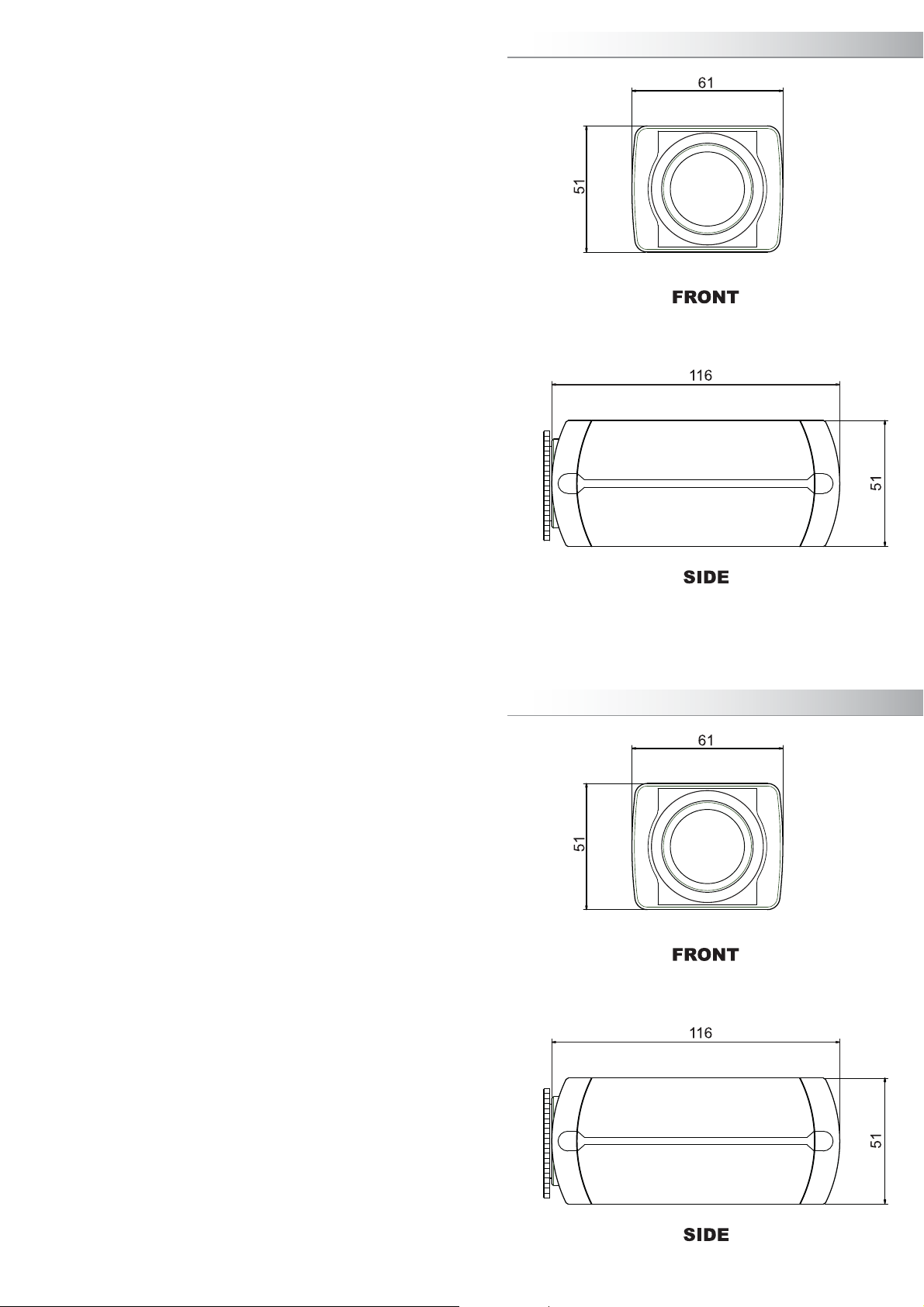
Dimensions
Dimensions
19
19
Specifications
SPECIFICATION
CCD
Horizontal Resolution
Effective Pixels
Scanning System
Synchronization
Min.lllumination
S/N ratio
Video Output
Scanning Frequency
Electronic Shutter Speed
Sens-up
3D-DNR
White Balance
BLC
AGC
Day & Night
WDR
Motion Detection
Privacy Masking
Mirror
Sharpness
Lens Mount
Power Source
Power Consumption
Operating Temperature
Operating Humidity
Dimensions (mm)
Weight(g)
PALNTSC
1/3" SONY II CCD
Color - 600TV lines / B&W - 700TV lines
)V(285x)H(357)V(494x)H(867
2:1 Interlace
Internal
0.12Lux(15IRE:Sense-up OFF) F1.2 / 0.0002Lux(15IRE:Sense-up ON) F1.2
52 dB Min (AGC Off)
1Vp-p Composite 75ȍ
15.734KHz(H)/ 59.94HZ (V) 15.625KHz (H) / 50Hz (V)
1/50 ~ 1/100,000sec1/60 ~ 1/100,000sec
OFF ~ x512
ON/OFF(OFF / LOW / MIDDLE / HIGH)
ATW / ACW / MANUAL / PUSH
ON / OFF
LOW / MIDDLE / HIGH / OFF
COLOR / BW / AUTO / EXT
ON / OFF(WDR LEVEL, WEIGHT)
ON / OFF
8Windows(Polygonal, 8Colors)
ON / OFF / V-FLIP, ROTATE
0 ~ 49
C/CS Mount(changeable)
DC12V(±10%) / AC24V(±10%) Dual Power regulated
180mA Max.
-10°C ~ +50°C
30% ~ 90% RH
61(W) x 51(H) x 116 (D)
340g
The lightning flash with an arrowhead symbol, within an equilateral triangle is
intended to alert the user to the presence of uninsulated “dangerous voltage”
within the product's enclosure that may be of sufficient magnitude to
constitute a risk of electric shock to persons.
The exclamation point within an equilateral triangle is intended to alert the user
to the presence of important operating and maintenance (servicing)
instructions in the literature accompanying the appliance.
INFORMATION - This equipment has been tested and found to comply with limits
for a Class A digital device, pursuant to part 15 of the FCC Rules. These limits are
designed to provide reasonable protection against harmful interference when the
equipment is operated in a commercial environment. This equipment generates,
uses, and can radiate radio frequency energy and, if not installed and used in
accordance with the instruction manual, may cause harmful interference to radio
communications.
Operation of this equipment in a residential area is likely to cause harmful
ce in which case the user will be required to correct the interference at his own
expense.
WARNING : Changes or modifications not expressly approved by the manufacturer
WARNING : To prevent electric shock and risk of fire hazards:
could void the user’s authority to operate the equipment.
Do NOT use power sources other than that specified.
Do NOT expose this appliance to rain or moisture.
This installation should be made by a qualified service person and
should conform to all local codes.
18

How to set up Function
How to Use the Camera
Features
Precautions
Components
Name and Functions of Parts
Installation Procedures
Lens
When usking an auto iris lens
When usking a CS-Mount lens
When usking a C-Mount lens
Connection a monitor
Connection power
How to Use the Camera
How to set up Function
6
7
9
10
10
11
12
13
13
15
15
15
16
16
17
17
Function Menu Structure
EXPOSURE
COLOR -WB MODE -R-Y GAIN -B-Y GAIN -RETURN
DAY&NIGHT -D&N MODE -LEAD TIME -BURST -RETURN
FUNCTION -MIRROR -SHARPNESS -GAMA -FREEZE
MOTION -ALARM -SET WINDOWS -ALL SET -ALL CLEAR
PRIVACY -MASK1 -MASK8 -RETURN
SYNC -SYNC MODE -V-PHASE -RETURN
COMMUNICATION -ADDRESS -BAUDRATE -PROTOCOL -RETURN
SPECIAL -TITLE -LANGUAGE -DPC -FILTER
EXIT -EXIT -SAVE&EXIT -FACTORY SET -RETURN
DC 12V
AC 24V
Setup Menu
-LENS -E.SHUTTER -BLC -WDR
-AGC -SENS-UP -RETURN
-NEGA -3D DNR -D.ZOOM -LSC
-ECLIPSE -DIS -RETURN
-SENSITIV -SHOW -DELAY TIME -RETURN
-RETURN
Features
Precautions
Components
Name and Functions of Parts
Installation Procedures
Lens
When usking an auto iris lens
When usking a CS-Mount lens
When usking a C-Mount lens
Connection a monitor
Connection power
How to Use the Camera
How to set up Function
17
How to Use the Camera
How to set up Function
6
7
9
10
10
11
12
13
13
15
15
15
16
16
17
17
Function Menu Structure
EXPOSURE
COLOR -WB MODE -R-Y GAIN -B-Y GAIN -RETURN
DAY&NIGHT -D&N MODE -LEAD TIME -BURST -RETURN
FUNCTION -MIRROR -SHARPNESS -GAMA -FREEZE
MOTION -ALARM -SET WINDOWS -ALL SET -ALL CLEAR
PRIVACY -MASK1 -MASK8 -RETURN
SYNC -SYNC MODE -V-PHASE -RETURN
COMMUNICATION -ADDRESS -BAUDRATE -PROTOCOL -RETURN
SPECIAL -TITLE -LANGUAGE -DPC -FILTER
EXIT -EXIT -SAVE&EXIT -FACTORY SET -RETURN
DC 12V
AC 24V
Setup Menu
-LENS -E.SHUTTER -BLC -WDR
-AGC -SENS-UP -RETURN
-NEGA -3D DNR -D.ZOOM -LSC
-ECLIPSE -DIS -RETURN
-SENSITIV -SHOW -DELAY TIME -RETURN
-RETURN
17

Installation Procedures
Connecting a Monitor
DC 12V
AC 24V
Connecting Power
Connecting to AC 24V Power (AC 24V Only application)
Don’t need to check AC Power’s polarity(AC+, AC-)
Additional Surge Protected Ground Use AC 24V, 100mA
power supply for this camera – Class 2
Connecting to 12V DC Power (DC 12V Only application)
Please check the polarity DC(+) and DC(-) & Ground
Use DC 12V, 200mA power supply for this camera
Specifications
Dimension
DC 12V
AC 24V
AC
DC 12V
AC 24V
18
19
16
5

WDR(Wide Dynamic Range)
G600 delivers a powerful Wide Dynamic Range ( Typ.100dB) to the camera to provide
the best pictures under extreme high contrasts between lightness and darkness. It compensates
a necessary light level automatically to get detailed information in the dark area without saturation
from the bright area.
600 TVL High Resolutions
It enables to get 600 TVL high resolutions at Color mode and 700 TV Lines at Black/White mode .
G600 technology performs vivid and obvious image output with ultra horizontal resolution by
using a own de-mosaic interpolation algorithm and the specialized built-in sharpness filter.
HIGH SENSITIVITY TRUE DAY&NIGHT
G600 DSP Day & Night function delivers the high quality of the color image and performs while
converting the color into monochrome automatically as under less than the specific level of the
sensitivity. It is more superior in the Sense-up function with x512 and 3D-DNR very effectively
to ensure a clear image in the darkness.
3D DNR(Digital Noise Reduction)
G600 DSP technology achieves 3D-DNR function excellently effectively to ensure a clear image
in the darkness.enables to keep this function automatically while operating the enables to keep
this function automatically while operating the enables to keep this function automatically while
operating the
ECLIPSE
G600 DSP technology enables to recognize a visible car enables to keep this function automatically
while operating the It is very useful in parking lot and highway tollgate applications.
PRIVACY MASKING (Polygonal, 8colors)
G600 DSP ensures to protect the privacy for the private and specific areas onto the video signal
output by polygonal specific areas onto the video signal output by polygonal the size and position
of masking area to be controlled easily and conveniently and 8 areas masking setting which is
user programmable in color, brightness and mosaic.
Installation Procedures
6
WDR(Wide Dynamic Range)
G600 delivers a powerful Wide Dynamic Range ( Typ.100dB) to the camera to provide
the best pictures under extreme high contrasts between lightness and darkness. It compensates
a necessary light level automatically to get detailed information in the dark area without saturation
from the bright area.
600 TVL High Resolutions
It enables to get 600 TVL high resolutions at Color mode and 700 TV Lines at Black/White mode .
G600 technology performs vivid and obvious image output with ultra horizontal resolution by
using a own de-mosaic interpolation algorithm and the specialized built-in sharpness filter.
HIGH SENSITIVITY TRUE DAY&NIGHT
G600 DSP Day & Night function delivers the high quality of the color image and performs while
converting the color into monochrome automatically as under less than the specific level of the
sensitivity. It is more superior in the Sense-up function with x512 and 3D-DNR very effectively
to ensure a clear image in the darkness.
3D DNR(Digital Noise Reduction)
G600 DSP technology achieves 3D-DNR function excellently effectively to ensure a clear image
in the darkness.enables to keep this function automatically while operating the enables to keep
this function automatically while operating the enables to keep this function automatically while
operating the
15
Installation Procedures
ECLIPSE
G600 DSP technology enables to recognize a visible car enables to keep this function automatically
while operating the It is very useful in parking lot and highway tollgate applications.
PRIVACY MASKING (Polygonal, 8colors)
G600 DSP ensures to protect the privacy for the private and specific areas onto the video signal
output by polygonal specific areas onto the video signal output by polygonal the size and position
of masking area to be controlled easily and conveniently and 8 areas masking setting which is
user programmable in color, brightness and mosaic.
6
15

Installation Procedures
Installation Procedures
DC 12V
AC 24V
714
DC 12V
AC 24V
714

Lens
Installation Procedures
Notes
Lens
138
Installation Procedures
Notes
138

Back
DC 12V
AC 24V
1. CAMERA
Back
DC 12V
AC 24V
912
1. CAMERA
912

Front
Bottom
10 11
Front
Bottom
10 11
 Loading...