

BC700VIR48 / BC700VVR42
User Manual
talossecurity.com
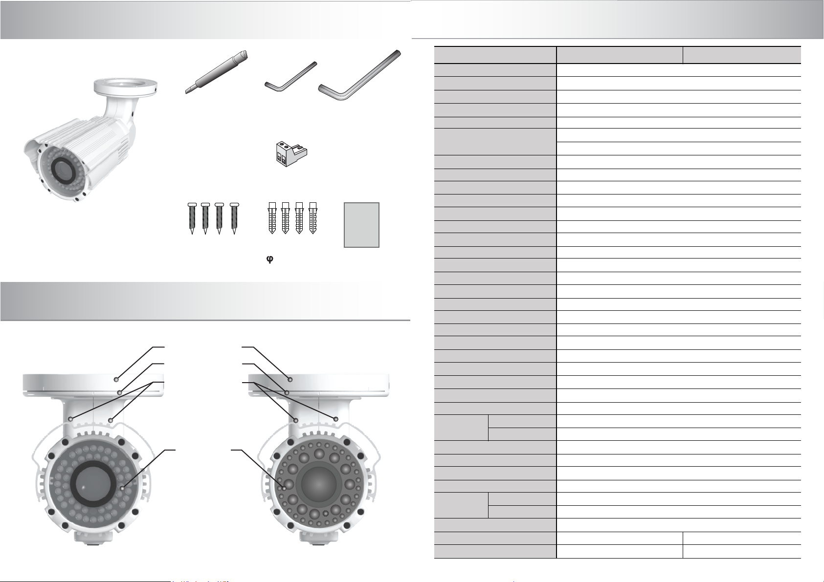
Components and Accessories
Specifications
Focus/Zoom
Adjustment Tool
CAMERA
Fixing Screw
S5X25(4EA)
Camera part name
Mountbase
Camera bass
Camera guard
Camera
B-620VVR42B-620VIR48
2.5mm
“L’wrench
“T’ Block
Anchor
4X30(4EA)
5mm
“L’wrench
Manual
Manual
MODEL
CCD
Horizontal Resolution
Effective Pixels
Scanning System
Synchronization
Min.lllumination
S/N ratio
Video Output
Scanning Frequency
Electronic Shutter Speed
OSD
Day & Night
ATW
High Speed Shutter
Flickerless
ATR
Auto Gain Control
Auto Iris
Camera ID
White Balance
DNR
Gamma Correction
Color Gain Control
Motion Detection
Privacy Masking
Etc. Function
B-620VIR42
Lens
B-620VIR48
Power Source
Power Consumption
Operating Temperature
Operating Humidity
B-700VIR42
Visible Range
B-700VIR48
(LED on)
Dimensions (HxDmm)
Camera
Package
BC700VVR42 BC700VIR48
1/3” SONY Ex-view HAD CCD II
700TV lines
976(H) x 494(V)
2 : 1 Interlace
Internal
0.02Lux@F1.2(Nomal color mode)
0Lux (LED On)
52dB (AGC off)
1Vp-p Composite 75Ω
H : 15,734KHz / V : 59.94Hz
1/60 ~ 1/120,000sec
Multi-language support
Auto / Color / BW
1800 ~ 1050K
1/60 (1/50) ~ 1/10Ksec
On / Off (External Optional)
On / Of
On / Off (Max level setting)
DC Auto Iris
On / Off (Max. 256, 8ea ID / 1Line)
ATW/Push/User1/User2/Anti CR/Manual/Push Lock
DNR Mode (Off, Y, C, Y/C) Level (0-15)
0.45
Level Setting
On / Off selectable (4 Programmable zones)
On / Off selectable (8 Programmable zones)
Sharpness, Reverse(H)
f = 6~50mm Aspheric AI Lens (F1.2)
f = 2.8~12mm Aspheric AI Lens (F1.2)
DC12V(±10%) / AC24V(±10%) regulated
700mA Max.
-10°C ~ +50°C
30% ~ 90% RH
48ea IR LED : 150ft
30ea IR LEDs & 12ea Super IR LEDs : 300ft+
120(W) X 140(H) X 254(D)mm
1,730g 1,740g
2,000g 2,010g

Dimension
140
95
87
120
Camera bracket function
PAN 360°
45°
42
45°
5
ROTATE 360°
FRONT
133
SIDE
254
MOUNT BASE
TILT 90°
PAN 360°
ROTATE 360°
TILT 90°

Camera installation
2.5mm
“L”wrench
Mountbase
Camera setting
1. ZOOM/FOCUS ADJUST MENT
1. Make desired viewing angle by using Focus/Zoom adjustment tool clockwise
or conunter clockwise as [PIC 1]
N
Focus
Video Jack
(BNC/RCA)
Cable Jack Setting
Video Signal
Video GND
Video Jack
Termial
Block
DC/AC Switched
Without
Nega(-)/Posi(+)
5mm
“L”wrench
Fixing Screw
Camera bass
Camera guard
Control Panel cover
2.CAMERA SETTING
Control Panel cover
[PIC 1]
[PIC 2]
T W
Focus/Zoom
Adjustment Tool
UP
RIGHT
LEFT
DOWN
Zoom
Joystick
Push
Menu / Enter
Extra Service Preview
Video output
1. On the ceiling(or wall), make the hole for Anchor and put the Anchor into
the hole completely.
Use Fixing Screw to settle (Anchor size :
4 / Lengh 30mm)
2. After settle the Bracket Base, use “L”wrench to settle the Camera Body
and Bracket Head
1. According to [PIC 2], open Control Panel cover to change the setting.
2. If necessary, change OSD setting for desired performance, at camera control
panel
* The extra service preview video out put can be used for installation with the
Portable monitor. ( For the camera setting, please check the OSD manu)
* Push the OSD joystick little more than 1sec., OSD manu will be appeared.
* Move the OSD joystick for change the setting.
* Push the OSD joystick for Enter and Set the setting.
3. After changing OSD setting, lock the control panel cover completely.
 Loading...