

Page 1
Backpack Blower Owners Manual
9096-320604
CAUTION • PLEASE READ
Before using this product, read this manual and follow all safety rules and operating
instructions.
WARRANTY INFORMATION
AU
1
LANDSCAPER PROFESSIONAL SERIES
BACKPACK BLOWER
6 MONTH COMMERCIAL WARRANTY
The benefits conferred by this warranty are in addition to all other conditions and warranties in respect
of this product which the consumer may have under the Trade Practices Act 1974 or by any legislation
of a State or Territory of Australia. This product is warranted by Talon Tools Australia (ABN 12 099 520
939) (The "Company") to be free from defects in material and workmanship for a period of 6 months
from the date of original purchase (for use in commercial applications) and 24 months (for home use).
The Company during the period of the warranty, will at its option, and subject to the conditions stated
herein, repair or replace without charge this product or any component part, which upon examination by
an Authorised Service Agent or by the Company is found to be defective.
Warranty conditions
(This warranty will not apply:
(i) where this product has been subjected to misuse, abuse, accident or want of care;
(ii) where this product has been used for a purpose for which it was not designed or suited.
(iii) where the service of this product has been undertaken by a person not authorised by the Company
to carry out such work or where parts have not been approved by the Company have been used.
Should service become necessary during the warranty period, the purchaser should contact an
Authorised Service Agent or the Company. In order to obtain warranty service, the purchaser must present the store receipt showing the name of the retailer and the date of purchase together with a completed Warranty Card. The period of the warranty begins from the original date of purchase, notwithstanding
any subsequent repair or parts replacement. No additional warranty or guarantee other than set out in
this document, whether written or verbal, is authorised to be made on the Company's behalf. The purchaser shall be responsible for delivery or causing the product to be delivered to the Company or the
Authorised Service Agent and the purchaser shall be responsible for all charges in connection with redelivery of the product and/or the delivery of parts. Damage in transit is not covered by this warranty and
purchasers should remove from the product any liquids (if applicable) before sending and pack the product securely to prevent damage.
Warranty exclusions
Normal wear parts or components are subject to separate terms as follows: Normal wear parts, components or service required when performing normal and regular maintenance of this product are not covered by warranty unless it is found to be defective by an Authorised Service Agent or by the Company.
Normal wear parts include, but are not limited to:
Returns based on the above listed normal wear parts will not be accepted under this warranty as they
are considered consumable items and are at the expense of the purchaser.
Lubricants Air Filters Carburettor Tune-Ups
Spark Plugs Fuel Filters
Safety Operation
Assembly Maintenance
Page 2
RULES FOR SAFE OPERATION
AU
3
NOTE: Advises you of information or instructions vital to
the operation or maintenance of the equipment.
Read the Operator’s Manual(s) and follow all warnings
and safety instructions.
Failure to do so can result in serious injury to the operator
and/or bystanders.
2
INTRODUCTION
AU
Congratulations on your purchase of a quality Talon Landscaper Professional Series product.
This manual covers the operation and maintenance of the T
alon AB3206 blower. Please read and understand this
manual before using your new blower. If assistance is required, please contact Talon Tools Australia or any Talon Tools
Authorised Servicing Dealer.
TABLE OF CONTENTS
AU
Warranty Page 1
Safety Rules Pages 3 - 6
General Identification Page 7
Oil and Fuel information Page 8
Assembly Pages 9 - 10
Starting / Stopping Instructions Pages 10 - 11
Operation Page 12
Maintenance Pages 13 - 15
Troubleshooting Page 16
Specifications Page 17
Talon T
ools Australia
5 Reaghs Farm Rd, Minto
NSW 2566 Australia
Tel: +61 02 9426 8888
Fax: +61 02 9426 8899
E-mail: [email protected]
Inter
net: www.talontools.com.au
The purpose of safety symbols is to attract your
attention to possible dangers. The safety symbols,
and their explanations, deserve your careful attention
and understanding. The safety warnings do not by
themselves eliminate any danger
. The instructions or
war
nings they give are not substitutes for proper
accident prevention measures.
SYMBOL
MEANING
SYMBOL MEANING
Indicates danger
,
warning or caution.
Attention is required in order to avoid serious personal injury. May be used in conjunction with other symbols or pictographs.
SAFETY ALERT:
Failur
e to obey a safety
war
ning will result in serious
injury to yourself or to others. Always follow
the safety pr
ecautions to reduce the risk of
fire, electric shock and personal injury.
DANGER:
Failure to obey a safety
warning can result in injury
to yourself and others. Always follow the
safety precautions to reduce the risk of fire,
electric shock and personal injury.
WARNING:
Failure to obey a safety
warning may result in property damage or personal injury to yourself
or to others. Always follow the safety precautions to reduce the risk of fire, electric
shock and personal injury.
CAUTION:
• IMPORTANT SAFETY INSTRUCTIONS •
READ ALL INSTRUCTIONS BEFORE OPERATING
• Read the instructions carefully. Be familiar with the
controls and proper use of the unit.
• Do not operate this unit when tired, ill, or under the
influence of alcohol, drugs, or medication.
• Children must not operate the unit. Teens must be
accompanied and guided by an adult.
• All guards and safety attachments must be installed
properly before operating the unit.
• Inspect the unit before use. Replace damaged parts.
Check for fuel leaks. Make sure all fasteners are in
place and secure. Replace parts that are cracked,
chipped, or damaged in any way. Do not operate the
unit with loose or damaged parts.
• Carefully inspect the area before starting the unit.
Remove all debris and hard or sharp objects such as
glass, wire, etc.
• Clear the area of children, by standers, and pets. At
a minimum, keep all children, by standers, and pets
outside a 50 feet (15 m.) radius; there still may be a
risk to by standers from thrown objects. By standers
should be encouraged to wear eye protection. If you
are approached, stop the unit immediately.
FUEL SAFETY WARNINGS
• Store fuel only in containers specifically designed
and approved for the storage of such material.
• Avoid creating a source of ignition for spilled fuel.
Do not start the engine until fuel vapors dissipate.
• Always stop the engine and allow it to cool before
filling the fuel tank. Never remove the cap of the
fuel tank, or add fuel, when the engine is hot. Never
operate the unit without the fuel cap securely in
place. Loosen the fuel tank cap slowly to relieve
any pressure in the tank.
• Add fuel in a clean, well-ventilated outdoor area
where there are no sparks or flames. Slowly remove
the fuel cap only after stopping engine. Do not
smoke while fueling or mixing fuel. Wipe up any
spilled fuel from the unit immediately. Always wipe
unit dry before using.
• Move the unit at least 30 feet (9.1 m) from the
fueling source and site before starting the engine.
Do not smoke. Keep sparks and open flames away
from the area while adding fuel or operating the
unit.
When using the unit, you
must follow the safety rules.
Please read these instructions before operating the unit in order to ensure the safety of
the operator and any by standers. Please
keep these instructions for later use.
WARNING:
Petrol is highly flammable,
and its vapors can explode
if ignited. Take the following precautions:
WARNING:
Page 3

RULES FOR SAFE OPERATION
AU
OTHER SAFETY WARNINGS
•
Always disconnect the spark plug before
performing maintenance or accessing movable
parts.
• Never store the unit, with fuel in the tank, inside a
building wher
e fumes may reach an open flame (pilot
lights, etc.) or sparks (switches, electrical motors,
etc.).
• Allow the engine to cool before storing or
transpor
ting. Be sure to secure the unit while
transpor
ting.
• Store the unit in a dry place, secured, or at a height
to prevent unauthorized use or damage. Keep out
of the reach of children.
• Never douse or squirt the unit with water or any
other liquid. Keep handles dry, clean, and free from
debris. Clean after each use, see Cleaning and
Storage
instructions.
• Keep these instructions. Refer to them often and
use them to instruct other users. If you loan this
unit to
others, also loan these instructions to them.
SPECIAL NOTE: Exposure to vibrations through
pr
olonged use of petrol powered hand tools could
cause blood vessel or ner
ve damage in the fingers,
hands, and joints of people prone to circulation
disorders or abnormal swelling. Prolonged use in cold
weather has been linked to blood vessel damage in
otherwise healthy people. If symptoms occur such as
numbness, pain, loss of strength, change in skin color
or texture, or loss of feeling in the fingers, hands or
joints, discontinue use of this tool and seek medical
attention. An anti-vibration system does not guarantee
avoidance of these problems. Users who operate power
tools on a regular basis must closely monitor their
physical condition and the condition of this tool.
SAVE THESE INSTRUCTIONS
RULES FOR SAFE OPERATION
AU
4
5
WHILE OPERATING
• Never start or run the unit inside a closed room or
building. Br
eathing exhaust fumes can kill. Operate
this unit only in a well-ventilated outdoor ar
ea.
•
Wear safety glasses or goggles that are marked as
meeting Australian standards and are marked as
such. Wear ear/hearing protection when operating
this unit.
• Never run the unit without the the proper equipment
attached. When using this unit, always install the
blower tubes depending on blower application.
• To reduce the risk of hearing loss associated with
sound level(s), always wear ear/hearing protection
when operating this unit.
• Wear heavy long pants, boots, gloves, and a long
sleeve shirt. Do not wear loose clothing, jewellery,
short pants, sandals, or go barefoot. Secure hair
above shoulder level.
• To avoid static electricity shock, do not wear rubber
gloves or any other insulated gloves while operating
this unit.
• Use the unit only in daylight or good artificial light.
• Keep outside surfaces free from oil and fuel.
• Avoid accidental starting. Be in the starting position
whenever pulling the starter rope. The operator and
unit must be in a stable position while starting.
Refer to
Starting/Stopping Instructions.
• Do not set unit on any surface except a clean, hard
area while engine is running. Debris such as gravel,
sand, dust, grass, etc. could be picked up by the
air intake and thrown out by the discharge opening,
damaging unit, property, or causing serious injury to
bystanders or operator.
• Use the right tool. Only use this tool for its intended
purpose.
• Do not force unit. It will do the job better and with
less likelihood of injury at a rate for which it was
designed.
• Do not overreach or use from unstable surfaces
such as ladders, trees, steep slopes, rooftops, etc.
Always keep proper footing and balance.
• Always hold the unit with a firm grip when
operating.
• Keep hands, face, and feet away from all moving
parts. Do not touch or try to stop the impeller when it
is rotating. Do not operate without guards in place.
• Do not put any object into openings. Do not use
with any opening blocked; keep free of dirt, debris,
and
anything that may reduce the air flow.
• Do not touch the engine or muffler. These parts get
extremely hot from operation, even after the unit is
turned off.
• Do not operate the engine faster than the speed
needed to do the job. Do not run the engine at high
speed when not in use.
• Always stop the engine when operation is delayed
or when walking from one location to another.
• Stop the engine for maintenance, repair, to install or
r
emove the blower tubes attachments. The unit
must be stopped and the impeller no longer tur
ning
to avoid contact with the rotating blades.
• If you strike or come into contact with a foreign
object, stop the engine immediately and check for
damage. Do not operate before repairing damage.
Do not operate the unit with loose or damaged
par
ts.
•
Use only original equipment manufacturer
replacement parts when servicing this unit. These
par
ts are available from your authorised service
dealer
. Do not use unauthorized parts, accessories,
or attachments for this unit. Doing so could lead to
serious injury to the user, or damage to the unit,
and void your warranty.
•
Never use this unit for spreading chemicals,
fertilizers or other substances which may contain
toxic materials.
• To reduce fire hazard, replace faulty muffler. Keep
the engine and muffler free from grass, leaves,
excessive grease or carbon build up.
• Turn the engine off and disconnect the spark plug
for maintenance or repair.
• Never point the blower or blowing debris in the
direction of people, animals or in the direction of
windows. Always direct the blowing debris away
from people, animals, and windows. Use extra
caution when blowing debris near solid objects
such as trees, automobiles, walls, etc.
Page 4
GENERAL IDENTIFICATION
AU
7
6
RULES FOR SAFE OPERATION
AU
SYMBOL MEANING
• SAFETY ALER
T SYMBOL
Indicates danger
, warning, or
caution. May be used in conjunction with other symbols or
pictographs.
• READ USER MANUAL
WARNING: Read the
Operator’s Manual(s) and follow
all warnings and safety
instructions. Failure to do so
can result in serious injury to
the operator and/or bystanders.
• WEAR EYE, HEARING AND
HARDHAT PROTECTION
WARNING: Thrown objects
and loud noise can cause
severe eye injury and hearing
loss. Wear eye protection
meeting Australian standards
and ear protection when
operating this unit. Falling
objects can cause severe head
injury. Wear head protection
when operating this unit.
Use a
full face shield when needed.
• MINIMUM OPERATING
DISTANCE
WARNING: Keep children,
bystanders, and animals 50 feet
(15 matres) away. If approached
stop unit immediately.
• UNLEADED FUEL
Always use clean, fresh
unleaded fuel.
• OIL
Refer to operator’s manual for
the proper type of oil.
SYMBOL MEANING
• ON/OFF CONTROL
ON/ST
ART
• ON/OFF CONTROL
OFF OR STOP
• CHOKE LEVER POSITIONS
1 • CHOKE
Position
2 • START Position
3 • RUN Position
SAFETY AND INTERNATIONAL SYMBOLS
This operator's manual describes safety and inter
national symbols and pictographs that may appear on this product.
Read the operator's manual for complete safety, assembly, operating and maintenance and repair information.
21
22
23
1
2
3
4
5
6
7
8
9
10
11
12
18
17
16
15
14
13
24
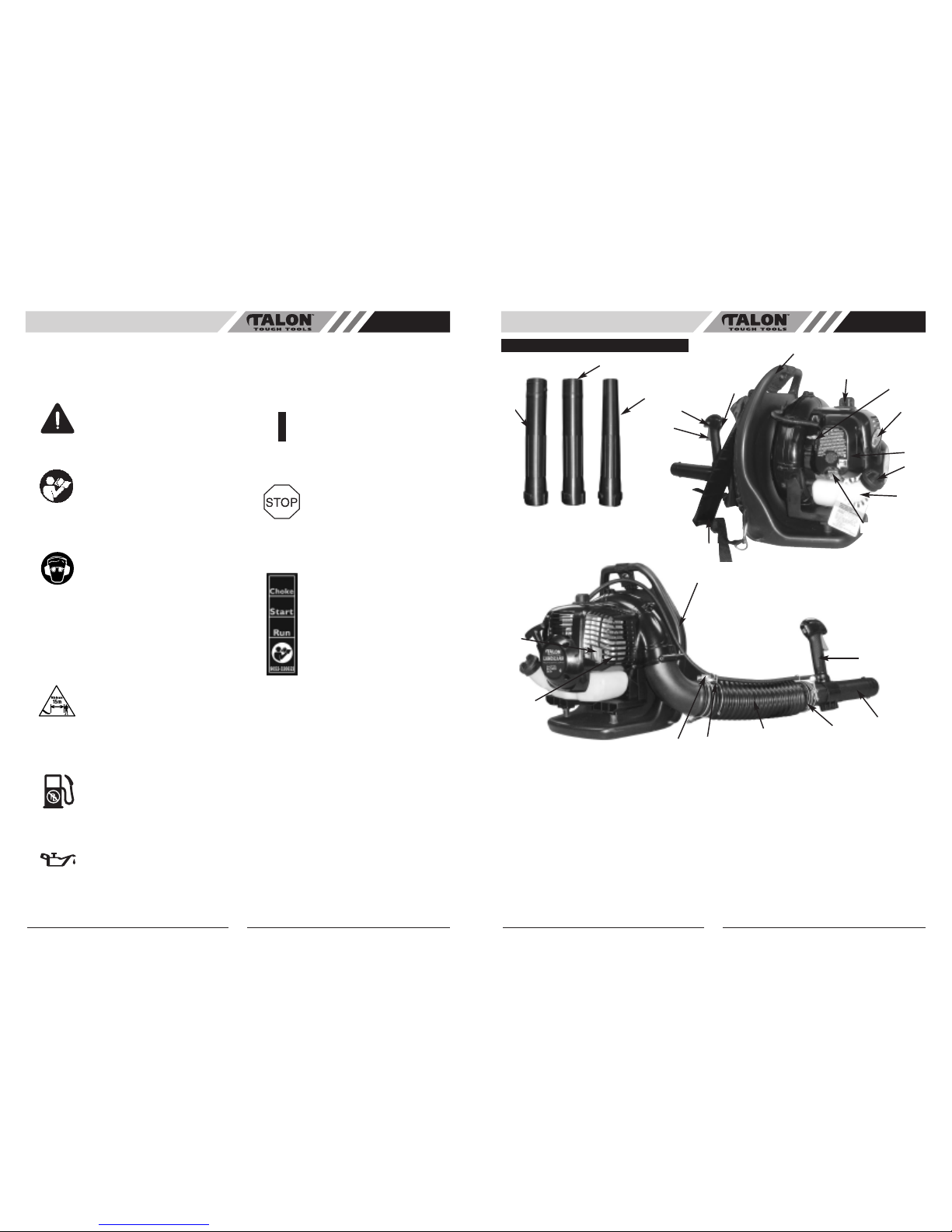
KNOW YOUR BLOWER
BLOWER COMPONENTS
1. THROTTLE TRIGGER
2. THROTTLE LOCK
3. ON/OFF IGNITION SWITCH
4. TOP ASSIST HANDLE
5. SPARK PLUG WIRE / SPARK PLUG
6. CHOKE LEVER
7. STARTER HANDLE
8. AIR CLEANER COVER
9. FUEL CAP
10. FUEL TANK
11. PRIMER BULB
12.
HARNESS
13.
CONTROL
HANDLE
14. OPERATING TUBE
15. HOSE CLAMP
16. FLEX TUBE
17. THROTTLE LINKAGE
18. MUFFLER COVER
19. SPARK ARRESTER SCREEN
20. VENTED BACK PAD
21. INTERMEDIATE TUBE
22. 56 mm NOZZLE
23.
45 mm CONCENTRA
T
OR NOZZLE
24. THROTTLE LINKAGE CLIPS
20
19
Page 5
OIL AND FUEL INFORMATION
AU
OIL AND FUEL MIXING INSTRUCTIONS
Old and/or improperly mixed fuel are the main reasons
for the unit not r
unning properly. Be sure to use fresh,
(less than 60 days old) clean unleaded fuel. Follow the
instr
uctions carefully for the proper fuel/oil mixture.
Definition of Blended Fuels
T
oday's fuels are often a blend of gasoline and
oxygenates such as ethanol, methanol, or MTBE (ether).
Alcohol-blended fuel absorbs water. As little as 1%
water in the fuel can make fuel and oil separate and
leads to formation of acids during storage. When using
alcohol-blended fuel, use fresh fuel.
Using Blended Fuels
If you choose to use a blended fuel, or its use is
unavoidable, follow recommended precautions:
• Always use the fresh fuel mix explained in your oper-
ator's manual
• Always agitate the fuel mix before fueling the unit
• Drain the tank and run the engine dry before storing
the unit
2 Stroke Oil
Use a good 2-stroke oil designed for air-cooled engines.
To Obtain Correct Fuel Mix:
Thor
oughly mix the proper ratio of 2-stroke engine oil
with unleaded petrol in a separate fuel can. Use a 25:1
fuel/oil ratio. Do not mix them directly in the engine fuel
tank. See the table below for specific petr
ol and oil mix-
ing ratios.
NOTE: Dispose of the old fuel/oil mix in accordance
to Federal, State and Local regulations.
MIXING RATIO - 25:1
For proper engine operation
and maximum reliability,
pay strict attention to the oil and fuel
mixing instructions on the 2 stroke oil
container. Using improperly mixed fuel can
severely damage the engine and will void
warranty.
CAUTION:
UNLEADED PETROL
2 STROKE OIL(not supplied)
5 LITRES
1 LITRE
200 ml
40 ml
+
Gasoline is extremely
flammable. Ignited Vapors
may explode. Always stop the engine and
allow it to cool before filling the fuel tank.
Do not smoke while filling the tank. Keep
sparks and open flames at a distance from
the area.
WARNING:
Remove fuel cap slowly to
avoid injury from fuel spray.
Never operate the unit without the fuel cap
securely in place
.
WARNING:
Add fuel in a clean, well
ventilated outdoor area.
Wipe up any spilled fuel immediately. Avoid
creating a source of ignition for spilled fuel.
Do not start the engine until fuel vapors
dissipate.
WARNING:
8
ASSEMBLY INSTRUCTIONS
AU
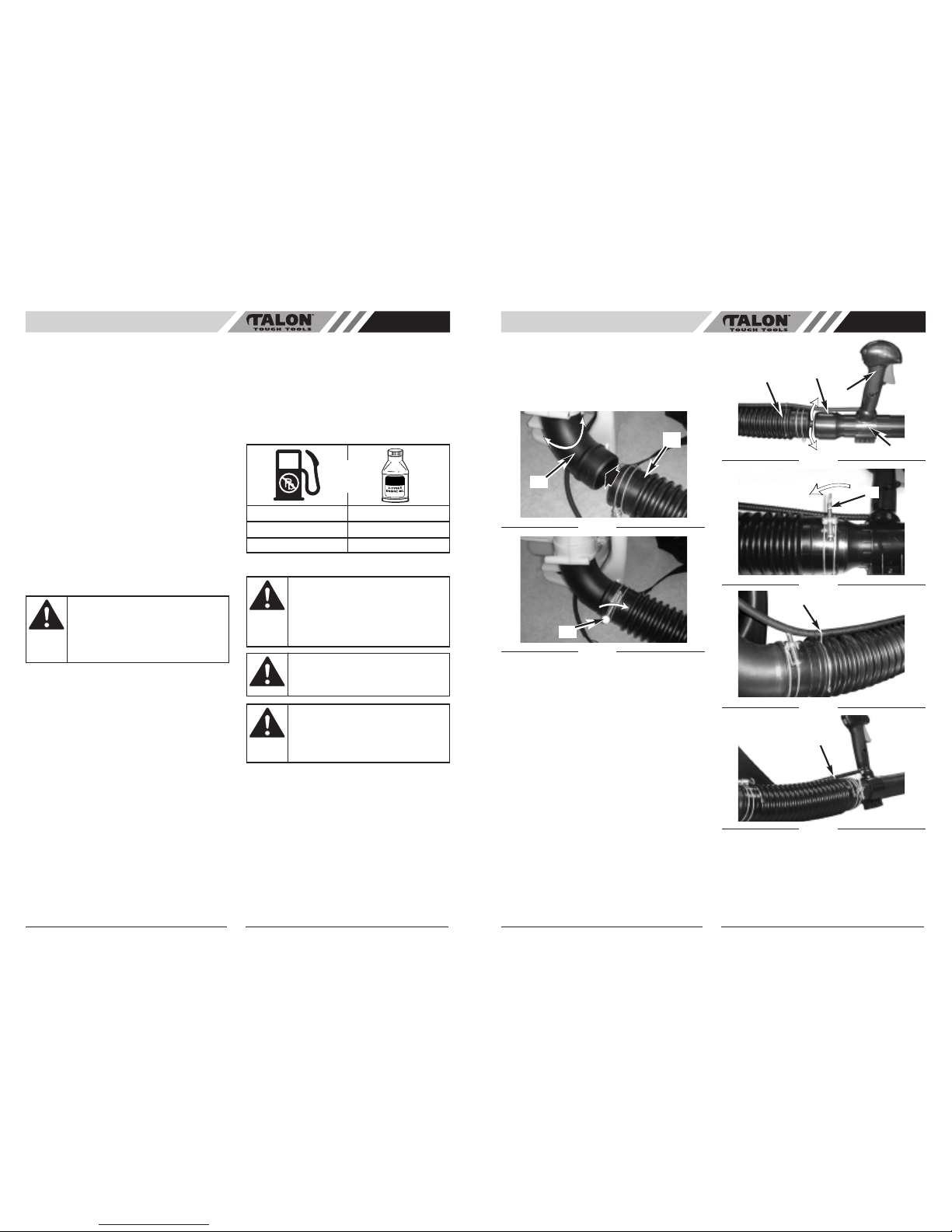
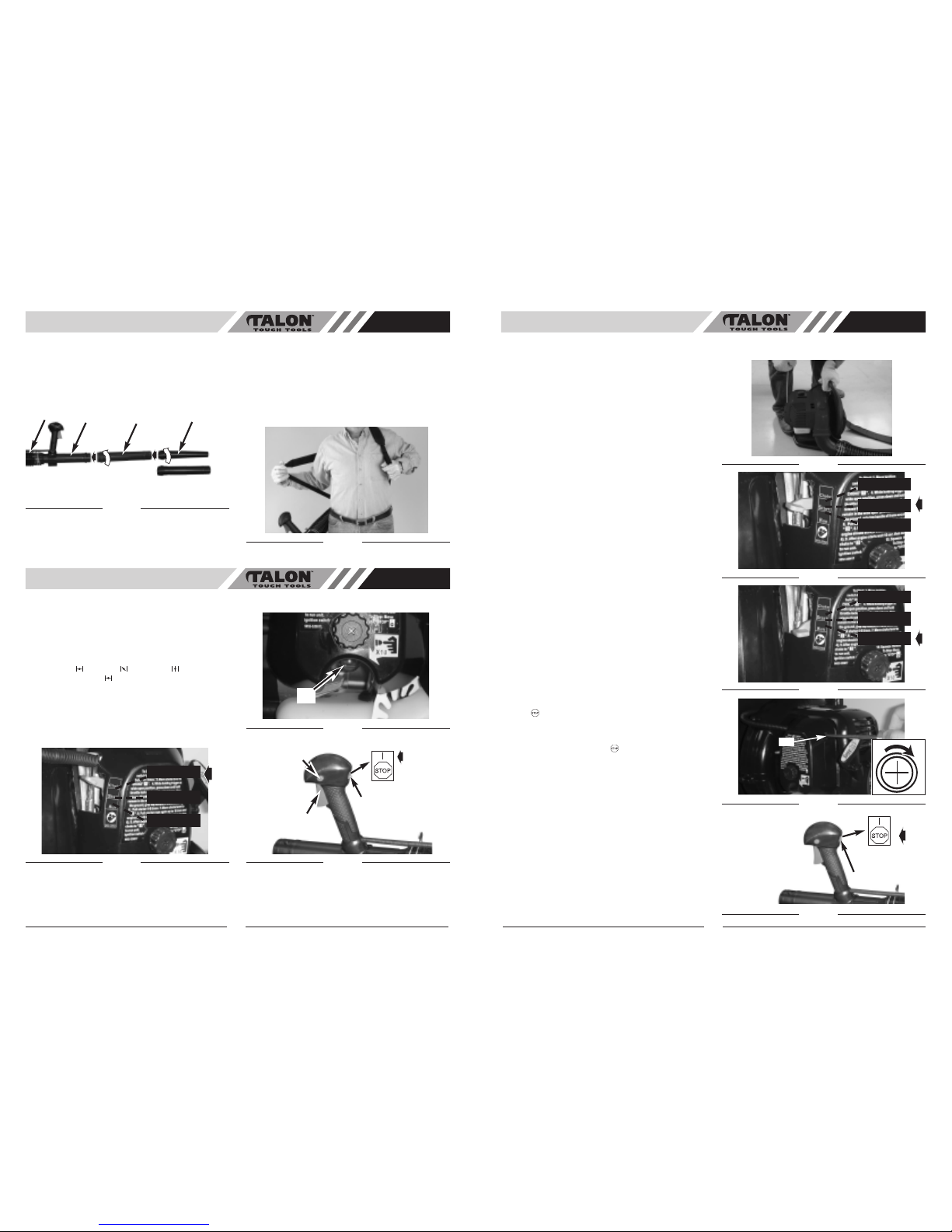
ATTACH FLEX TUBE
Put the hose clamp(C) on the flex tube befor
e
connecting the flex tube and the fan’s outlet tube
together.
Connect the flex tube (B) to the fan’s outlet tube (A) (Fig.
1) with a hose clamp (C) (Fig. 2) and tighten secur
ely
(Fig. 2).
ATTACH OPERATING TUBE
NOTE: keep the throttle cable as straight as possible
when connecting the blower tubes.
1. Place the unit on flat surface during assembly.
Insure screw mechanism of clamp is positioned
away from operator.
2. Put the hose clamp(C) on the flex tube and the
operating tube together.
3. Turn the rotary ring mark(D) so it aligns with the
throttle handle (F). Insert the operating tube (E) into
the flex tube (B) (Fig. 3) and then tighten securely
with a hose clamp (G)(Fig. 4).
4. Attached throttle linkage clips (# 23 - general
identification) - to both ends of the flex tube to
secure the throttle cable. ( See Fig. 5 and Fig. 6)
9
Fig. 1
B
A
Fig. 2
C
F
B
G
THROTTLE LINKAGE CLIPS
THROTTLE LINKAGE
CLIPS
D
180˚
E
Fig. 3
Fig. 4
Fig. 5
Fig. 6
Page 6
ASSEMBLY INSTRUCTIONS
AU
ATTACH INTERMEDIATE TUBE AND
CONCENTRATOR NOZZLE
Connect the intermediate tube (H) and air nozzle (I).
Push the tubes together and turn them clockwise so
that they lock together
. (Fig. 7)
ADJUST BACK PACK HARNESS AND
CONTROL HANDLE
1. Place blower on your back by slipping arms
through the shoulder straps as if you were putting
on a jacket (Fig. 8).
2.
Once adjustments have been made, to the straps
for user comfor
t, remove the blower from your back
and place on level gr
ound in an upright position.
3.
Adjust backpack harness and control handle.
10
STARTING/STOPPING
INSTRUCTIONS
AU
B
D
H
I
45mm
56mm
Fig. 7
Fig. 8
STARTING A COLD ENGINE
Fill fuel tank with proper gas and oil mixture. See FUEL
AND LUBRICATION. Set unit on ground so that it rests
on the back pack frame.
1. Pump primer bulb 10X by pressing up on the bulb(D).
(Fig. 10)
2. Your unit is designed with a 3 position choke:
CHOKE “ ”, START “ ”, and RUN “ ”. Move choke
lever to CHOKE “ ” position. (Fig. 9)
3. Set throttle lock (C): While holding trigger (B) at wide
open position, press down and hold throttle lock (C).
Release throttle trigger (B), then release throttle lock
(C). Throttle trigger (B) will now remain in the wide
open position. Make sure ignition switch is in the ON
(I) position. (Fig. 11)
Fig. 9
Fig. 10
Fig. 11
A
C
B
Choke
Run
Start
D
STARTING/STOPPING
INSTRUCTIONS
AU
NOTE: The unit uses the SUPER START STARTING
SYSTEM, which significantly r
educes the effort required
to star
t the engine. You must pull the starter rope out far
enough to hear the engine attempt to start. There is no
need to pull the rope briskly--there is no harsh
r
esistance when pulling. Be aware that this starting
method is vastly different from (and much easier than)
what you may be used to.
4. With the unit on the ground, hold the top assist
handle and step on the bottom of the frame with
foot.
(Fig.12)
5. Pull starter rope 4-6 times-if unit does not start
move choke lever to position 2 and pull 4-6 more
times (Fig. 13). Wait 10 sec. after unit starts then
move choke lever to position 3. (Fig.14)
6. Press trigger to run.
NOTE: If engine fails to start after repeated attempts,
refer to Troubleshooting section.
NOTE: Always pull starter rope straight out. Pulling
starter at an angle will cause rope to rub against the
eyelet. This friction will cause the rope to fray and wear
more quickly. Always hold starter handle when rope
retracts. Never let a rope snap back from extended
position. This could cause rope to snag or fray and also
damage the starter assembly.
IMPORTANT IDLING INFORMATION
In some cases due to operating conditions (altitude,
temperature etc.) your blower may need a slight
adjustment to the idle speed.
After warm up, If unit does not Idle after restarting 2
times, follow these steps to adjust idle.
1. Locate the idle adjustment screw (G) on the c
arburetor (Fig. 15).
2. Using a Phillips or slotted screwdriver - turn screw
1/4 to 1/2 turn clockwise (to the right). Unit should
then idle properly.
STOPPING THE ENGINE
Emergency Stopping Procedure. When it is necessary
to stop blower engine immediately, PRESS the OFF
“STOP ” switch (A) until the engine stops completely
(Fig.16).
Normal Stopping Method. For normal stopping,
release trigger and allow engine to return to idle speed.
Then PRESS the OFF “STOP ” switch (A) until the
engine stops completely. (Fig. 16)
STARTING A WARM ENGINE (Engine has
been stopped for no more than 15-20 minutes)
1. Set throttle latch (see step 2 for starting a cold
engine), pull starter rope briskly
.
2. If engine does not start, or starts and then stops after
5 rope pulls, follow procedure “STARTING A COLD
ENGINE”.
Fig. 13
Fig. 12
11
Choke
Run
Start
Fig. 14
Choke
Run
Start
G
Fig. 15
Fig. 16
A
Page 7
OPERATION
AU
BLOWER OPERATIONS
1.
Use the blower for trees, shrubs, flower beds, and
hard-to-clean areas.
2. Use the unit around buildings and for other normal
cleaning pr
ocedures.
3.
Use the blower around walls, overhangs, fences,
and scr
eens.
4. We recommend that a face mask be worn when
operating blower in dusty areas.
5. Stand away from the debris, at a distance that will
easily allow you to control the direction of blown
debris. Never blow debris in direction of
bystanders.
6. To control velocity of airstream, blower can be
operated at any speed between idle and full
throttle. Experience with the unit will help you
determine the amount of airflow necessary for each
application.
7. Operate power equipment only at reasonable
hours--not early in the morning or late at night
when people might be disturbed. Comply with
times listed in local ordinances.
8. To reduce sound levels, limit the number of pieces
of equipment used at any one time.
9. Operate power blowers at the lowest possible
throttle speed to do the job.
10. Check your equipment before operation, especially
the muffler, air intakes and air filters.
11. Use rakes and brooms to loosen debris before
blowing.In dusty conditions, slightly dampen
surfaces when water is available.
12. Conserve water by using power blowers instead of
hoses for many lawn and garden applications,
including areas such as gutters, screens, patios,
grills, porches and gar
dens.
13. Watch out for children, pets, open windows or
freshly washed cars, and blow debris safely away.
14. Use intermediate tube plus nozzle of your choice so
the airstream can work close to the ground.
15. After using blowers and other equipment, CLEAN
UP! Dispose of debris in trash r
eceptacles.
OPERATION INSTRUCTIONS
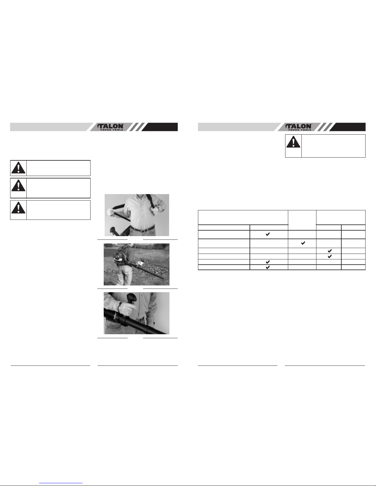
1.
Follow the instructions “STARTING A COLD
ENGINE”.
2. Once unit is running, place unit on your back by
slipping ar
ms through the shoulder straps as if your
wer
e putting on a jacket (Fig. 17).
3.
When preparing to clear an area of debris, always
position yourself so that you can contr
ol the direc-
tion debris will be blown .
4.
The control handle (A, Fig. 16) and the flexibility of
the blower tube assembly will allow you to clear the
most hard-to-reach areas .
5. The hand grip, throttle trigger, throttle lock and
ignition on/off switch (B) are all mounted on a swivel handle that offers a wide range of operating
positions and comfort (Fig. 19).
Fig. 17
Fig. 18
12
Fig. 19
DO NOT operate the blower
with other people or animals
in the immediate vicinity. Allow a minimum
of 50 feet (15 metres) between operator
and other people or animals.
CAUTION:
Because of flying debris,
always wear approved
shielded safety glasses or face shield when
operating blower
.
WARNING:
Before using your blower,
review Safety Precautions
in your User Manual, and all regulations for
operation of the unit. These precautions
and regulations are for your protection.
WARNING:
MAINTENANCE AND REPAIR
INSTRUCTIONS
AU
MAINTENANCE SCHEDULE
Perform these required maintenance procedures at the
frequency stated in the table. These procedures should
also be a part of any seasonal tune-up.
NOTE: Maintenance, r
eplacement, or repair of the
emission control devices and system may only be
performed by a qualified service dealer.
13
To prevent serious injury,
never per
form maintenance
or r
epairs with unit running. Always service
and r
epair a cool unit. Disconnect the spark
plug wire to ensure that the unit cannot
start.
WARNING:
A good preventive maintenance program of regular inspection and care will increase life and improve performance of
your blower. This maintenance checklist is a guide for such a program.
Cleaning, adjustment, and part replacement may be required, under certain conditions, at more frequent intervals than
those indicated.
CUSTOMER RESPONSIBILITY
MAINTENANCE CHECKLIST
AFTER
EACH USE
HOURS OF
OPERATION
CHECK FOR LOOSE
SCREWS/ NUTS/BOLTS
BEFORE EACH USE
CLEAN OR REPLACE THE
FILTER
ITEM
REPLACE FUEL FILTER
REPLACE SPARK PLUG
INSPECT VACUUM TUBES
INSPECT FUEL HOSES
10 20
Page 8
MAINTENANCE AND REPAIR
INSTRUCTIONS
AU
AIR FILTER
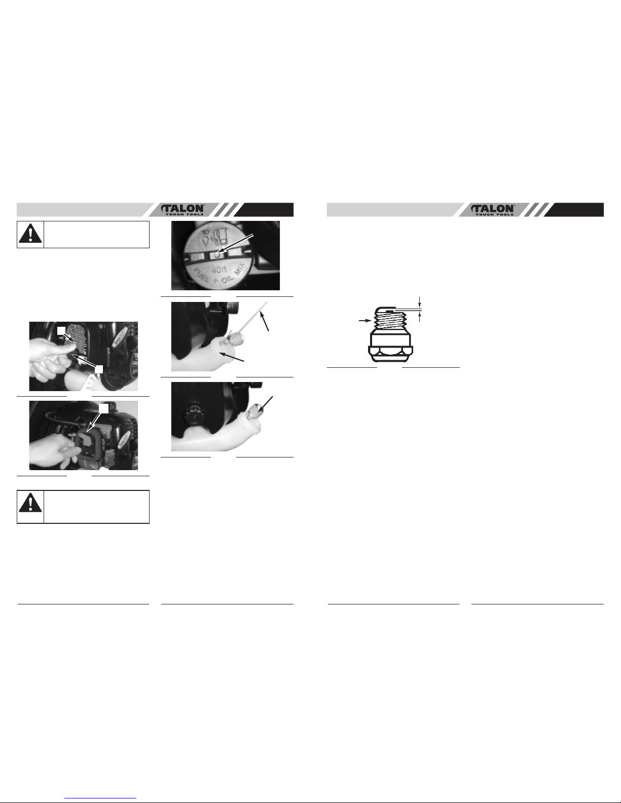
T
o Clean Air Filter:
1. Loosen knob (A) holding air filter cover in place,
remove cover (B) and lift filter (C) from air box (Fig.
20 & Fig. 21).
2.
Wash filter in soap and water.
DO NOT USE
GASOLINE!
3. Air dry filter.
4. Reinstall filter.
NOTE: Replace filter if frayed, torn, damaged or unable
to be cleaned.
FUEL CAP / FUEL FILTER
NOTE: Keep vent (A) on fuel cap clean of debris (Fig.
22).
Fuel Filter:
1. Completely remove fuel cap from fuel tank (B) to be
able to remove fuel filter (C) from tank. Use a piece
of wire (C) with a hook formed at the end to pull
filter out of tank. (Fig. 23)
2.
Pull filter (D) of
f with a twisting motion. (Fig. 24)
3. Replace fuel filter (D). (Fig. 24)
NOTE: Never operate the blower without the fuel filter.
Internal engine damage could result!
IDLE ADJUSTMENT
The carburetor was pre-set at the factory for optimum
performance. If further adjustments are necessary take
your blower to a qualified service dealer.
Fig. 20
Fig. 21
14
Fig. 24
NEVER operate blower
without the air filter
. The air
filter must be kept clean. If it becomes
damaged, install a new filter.
CAUTION:
MAINTENANCE AND REPAIR
INSTRUCTIONS
AU
SPARK PLUG
1.
To remove spark plug for cleaning or replacement:
make sure engine is off, spark plug is cool, then
grasp spark plug boot firmly and remove from spark
plug. Remove spark plug with cor
rect spark plug
tool. Inspect, clean or r
eplace as needed.
2.
Spark plug gap = .025" (.635mm) (Fig. 25).
3.
Torque to 105 to 130 inch pounds (12 to 15 N•m).
Connect spark plug boot.
4.
If needed replace spark plug with Champion RZ7C
or equivalent.
STORAGE
Failure to follow these steps may cause varnish to form
in the carburetor which can cause difficult starting or
permanent damage following storage.
1. Perform all the general maintenance recommended
in the Maintenance Section of your User Manual.
2. Clean exterior of engine and blower tubes.
3. Drain fuel from the fuel tank by running the unit dry
or by removing the fuel cap and tipping the motor
housing/fuel tank over and draining oil/fuel mixture
into a container with the same 2 stroke fuel mixture.
4. After fuel is drained, start engine.
5. Run engine at idle until unit stops. This will purge
the carburetor of fuel.
6. Allow engine to cool (approx. 5 minutes).
7. Using a spark plug wrench, remove the spark plug.
8. Pour 1 teaspoon of clean 2-stroke oil into the
combustion chamber. Pull starter rope slowly several times to coat internal components. Replace
spark plug.
9. Store unit in a cool, dry place away from any source
of ignition such as an oil burner, water heater, etc.
REMOVING A UNIT FROM STORAGE
1. Remove spark plug.
2.
Pull starter rope briskly to clear excess oil from
combustion chamber
.
3. Clean and gap spark plug or install a new spark
plug with proper gap. (Fig. 25)
4.
Prepare unit for operation.
5. Fill fuel tank with proper fuel / oil mixture. See Fuel
and Lubrication Section.
Fig. 17
15
B
A
C
Remove fuel from unit and
store in approved container
before starting this procedure. Open fuel
cap slowly to release any pressure which
may have formed in fuel tank.
CAUTION:
Fig. 22
Fig. 23
A
C
B
D
.025" (.635mm)
Spark
Plug
Page 9

TROUBLESHOOTING
AU
16
SPECIFICATIONS
AU
17
UNIT WON’T START OR STARTS BUT WILL NOT RUN
CAUSE ACTION
1. Incorrect starting procedures 1. Follow instructions in the Starting/Stopping section
2. Incor
rect carburetor mixture adjustment setting 2. Have carburetor adjusted by a qualified service dealer
3. Fouled spark plug 3. Clean/gap or replace plug
4. Empty fuel tank 4. Fill fuel tank with properly mixed fuel
5. Primer bulb was not pressed enough 5. Press primer bulb fully and slowly 10 times
CAUSE ACTION
1. Fuel filter is plugged 1. Replace the fuel filter
2. Incorrect choke lever position 2. Move to RUN Position
3. Dirty air filter 3. Remove, clean and reinstall filter
4. Incorrect carburetor mixture adjustment setting 4. Have carburetor adjusted by a qualified service dealer
ENGINE HESITATES
CAUSE ACTION
1. Incorrect carburetor mixture adjustment setting 1. Have carburetor adjusted by a qualified service dealer
2. Air filter is plugged 2. Replace or clean the air filter
3. Old or improperly mixed fuel 3. Drain gas tank/add fresh fuel mixture
NO POWER UNDER LOAD
CAUSE ACTION
1. Incorrect carburetor mixture adjustment setting 1. Have carburetor adjusted by a qualified service dealer
2. Old or improperly mixed fuel 2. Drain fuel tank (see Storage)/add fresh fuel mixture
3. Air filter is plugged 3. Replace or clean the air filter
4. Fouled spark plug 4. Replace or clean the spark plug
RUNS ERRATICALLY
CAUSE ACTION
1. Incorrectly gapped spark plug 1. Clean/gap or replace plug
2. Dirty air filter 2. Clean or replace air filter
SMOKES EXCESSIVELY
CAUSE ACTION
1. Incorrect carburetor mixture adjustment setting 1. Have carburetor adjusted by a qualified service dealer
2. Incorrect fuel mixture 2. Use properly mixed fuel (25:1 mixture)
NOTE: For repairs beyond the minor adjustments listed above, contact your nearest Talon Servicing Dealer.
UNIT STARTS, BUT ENGINE HAS LOW POWER
Engine Type. . . . . . . . . . . . . . . . . . . . . . . . . . . . . . . . . . . . . . . . . . . . . . . . . . . . . . . . . . . . . . . Air-Cooled, 2-Stroke
Displacement . . . . . . . . . . . . . . . . . . . . . . . . . . . . . . . . . . . . . . . . . . . . . . . . . . . . . . . . . . . . . 30 cc
Idle Speed RPM . . . . . . . . . . . . . . . . . . . . . . . . . . . . . . . . . . . . . . . . . . . . . . . . . . . . . . . . . . . 3,400 - 4,400 rpm
Operating RPM . . . . . . . . . . . . . . . . . . . . . . . . . . . . . . . . . . . . . . . . . . . . . . . . . . . . . . . . . . . . 7,200+ rpm
Ignition T
ype . . . . . . . . . . . . . . . . . . . . . . . . . . . . . . . . . . . . . . . . . . . . . . . . . . . . . . . . . . . . . . Electronic
Ignition Switch . . . . . . . . . . . . . . . . . . . . . . . . . . . . . . . . . . . . . . . . . . . . . . . . . . . . . . . . . . . . Rocker Switch
Spark Plug Gap. . . . . . . . . . . . . . . . . . . . . . . . . . . . . . . . . . . . . . . . . . . . . . . . . . . . . . . . . . . . 0.025 in. (0.635 mm)
Lubrication . . . . . . . . . . . . . . . . . . . . . . . . . . . . . . . . . . . . . . . . . . . . . . . . . . . . . . . . . . . . . . . Fuel/Oil Mixture
Fuel/Oil Ratio . . . . . . . . . . . . . . . . . . . . . . . . . . . . . . . . . . . . . . . . . . . . . . . . . . . . . . . . . . . . . 25:1
Carburetor. . . . . . . . . . . . . . . . . . . . . . . . . . . . . . . . . . . . . . . . . . . . . . . . . . . . . . . . . . . . . . . . with primer
Starter . . . . . . . . . . . . . . . . . . . . . . . . . . . . . . . . . . . . . . . . . . . . . . . . . . . . . . . . . . . . . . . . . . . Super Start Rope Pull
Muffler . . . . . . . . . . . . . . . . . . . . . . . . . . . . . . . . . . . . . . . . . . . . . . . . . . . . . . . . . . . . . . . . . . . Baffled with Guard
Fuel Tank Capacity . . . . . . . . . . . . . . . . . . . . . . . . . . . . . . . . . . . . . . . . . . . . . . . . . . . . . . . . . 550 ml
Throttle Control. . . . . . . . . . . . . . . . . . . . . . . . . . . . . . . . . . . . . . . . . . . . . . . . . . . . . . . . . . . . Finger-Tip Trigger
Blower Air Velocity . . . . . . . . . . . . . . . . . . . . . . . . . . . . . . . . . . . . . . . . . . . . . . . . . . . . . . . . . 290 km/h
Blower Air Output . . . . . . . . . . . . . . . . . . . . . . . . . . . . . . . . . . . . . . . . . . . . . . . . . . . . . . . . . . 13.11 m
3
/min
Approximate Unit Weight (No fuel) . . . . . . . . . . . . . . . . . . . . . . . . . . . . . . . . . . . . . . . . . . . . 6.4 kg
Use goggles and hearing protection
ENGINE *
BLOWER
 Loading...