

Page 1

USER MANUAL
Petrol Line Trimmer
9096-336404
SAFETY
OPERATION
MAINTENANCE
Worn Bump Head
Trimming line.
Spark Plugs.
Carburetor Tune-ups.
Lubricants.
Starter Assemblies.
Engine Tune-ups.
Filters.
LINE TRIMMER WARRANTY
The benefits conferred by this warranty are in addition to all other conditions and warranties in respect of
this product which the consumer may have taken under the Trade Practices Act 1974 or by any legislation
of a State or Territory of Australia. This product is warranted by Talon Tools Australia (ABN 12 099 520
939)(the “Company”) to be free from defects in material and workmanship for a period of 24 months from
the date of original purchase. The Company during the period of the warranty, will at its option, and subject
to the conditions stated herein, repair or replace without charge this product or any component part, which
upon examination by an Authorised Service Agent or by the Company is found to be defective.
Wa r r a n ty co n d i tio ns
This warranty will not apply:
(i) where this product has been subjected to misuse, abuse, accident or want of care;
(ii) where this product has been used for a purpose for which it was not designed or is not suited;
(iii) where the service of this product has been undertaken by a person not authorised by the Company
to carry out such work or where parts that have not been approved by the Company have been used;
(iv) where this product has been used for industrial or commercial purposes.
Should service become necessary during the warranty period, the purchaser should contact an Authorised
Service Agent or the Company. In order to obtain warranty service, the purchaser must present the store
receipt showing the name of the retailer and the date of purchase together with a completed Warranty
Card. The period of the warranty begins from the original date of purchase, notwithstanding any subsequent repair or parts replacement. No additional warranty or guarantee other than set out in this document,
whether written or verbal, is authorised to be made on the Company's behalf. The purchaser shall be
responsible for delivery or causing the product to be delivered to the Company or the Authorised Service
Agent and the purchaser shall be responsible for all charges in connection with re-delivery of the product
and/or the delivery of parts. Damage in transit is not covered by this warranty and purchasers should
remove from the product any liquids (if applicable) before sending and pack the product securely to prevent
damage.
Wa r r a n ty ex c l u sio ns
Normal wear parts or components are subject to separate terms as follows: Normal wear parts, components or service required when performing normal and regular maintenance of this product are not covered
by warranty unless it is found to be defective by an Authorised Service Agent or by the Company. Normal
wear parts include, but are not limited to:
Returns based on the above listed normal wear parts will not be accepted under this warranty as they
are considered consumable items and are at the expense of the purchaser.
2
WARNING • PLEASE READ
For your own safety please read this manual before attempting to operate your new unit. Failure to follow
instructions can result in serious personal injury. Spend a few moments to familiarize yourself with your trimmer
before each use.
AU
WARRANTY INFORMATION
MODEL NO. AT33641
Page 2
AU
3
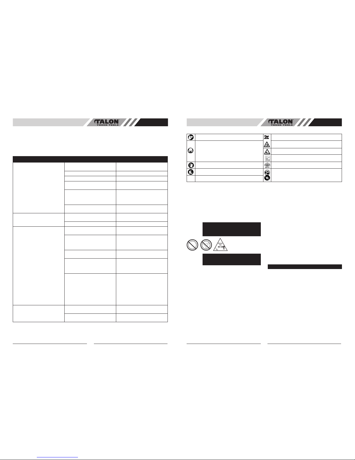
GENERAL TROUBLESHOOTING GUIDE
Unit will not start. Incorrect starting procedures. Follow correct starting procedures in user
manual.
ON/OFF switch in the “OFF” position. Turn ON/OFF switch to the “ON” position.
Primer bulb not pressed 10 times. Press primer bulb 10 times.
Throttle trigger not fully depressed when
starting.
Ensure that the throttle trigger is
depressed when starting.
Incorrect fuel/oil mix. Ensure that the correct fuel/oil mix (25:1
mixture) is used. Too little oil will damage
the engine while too much oil will foul the
spark plug.
Dirty spark plug. Check that the spark plug is clean and
properly fitted.
Not running smoothly. Dirty air cleaner. Check air cleaner is free and clear of
blockages.
Stale fuel. Drain and use fresh fuel.
Trimming line will not feed. No line in head. Check to see that there is line in the head.
If not replace with 2.0mm trimming line.
Line has been wound incorrectly around
spool.
Ensure that the line has been wound
in the correct direction. Refer to the
“Replacing Trimming Line” section of this
user manual.
Incorrect size line used. Ensure that only 2.0mm size line is used
in this machine.
Inner spool. Check the inner spool for dirt, burs or
warping. Excessive heat build-ups can
cause damage to the inner spool. If spool
is damaged, replace inner spool.
Worn bump head. If the bump knob has excessive wear it
indicates that the head is being rubbed
on the ground during operation or is being
“tapped” on a concrete surface. Both
these situations can contribute to line
feed, and other product problems. The
cutting head should be off the ground
at all times when cutting and the head
should only be “tapped” on a flat surface.
No drive to shaft. Bump head incorrectly installed. Ensure that the bump head is correctly
fitted.
Collars and spacers incorrect fitted
(Straight shaft units only).
Ensure that the collars and spacers are
correctly fitted.
The following basic troubleshooting checks can be easily carried out to determine whether or not the unit is running correctly. If the unit will not operate after these checks then the product should be taken to an Authorised Service Agent for
further inspection.
Ensure a small amount of fresh 2 stroke fuel (25:1 fuel:oil) is either in the tank or available for use during
troubleshooting.
4
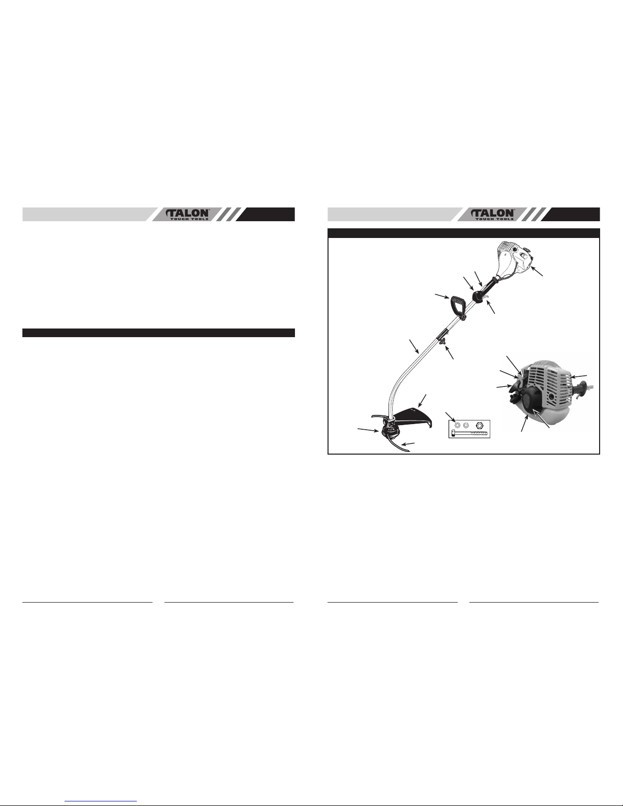
Meaning of symbols marked on the product
Read the user manual before using the machine
Whenever the machine is in use, safety goggles must
be worn to safeguard against flaying object, as must
ear protectors, such as a soundproof helmet, in order to
protect the operator ’s hearing. If the operator is working
in an area where there is a risk of falling objects, a safety
helmet must also be worn.
Warning! Hot surface
Keep people or animals at least 15m away from the
machine during operation
Wear gloves to protect your hands
Wear safety boots to protect against electric shock
Danger : Objects thrown up by machine
Acoustic power level LWA accordance with directive
2000/14/EC
Maximum revolution frequency of the drive shaft
Never use blades
WARNING! When using petrol tools, basic safety precautions, including the following, should always be followed to
reduce the risk of serious personal injury and/or damage to the unit.
Read all these instructions before operating this product and save these instructions.
This power unit can be dangerous! Operator is responsible for following unit manual instructions and warnings.
Read entire operator’s manual before using unit! Be
thoroughly familiar with the controls and the proper use of
the unit. Restrict the use of this unit to persons who read,
understand, and follow unit, manual instructions and warn
-
ings. Never allow children to operate this unit.
1. Wear close fitting, tough work clothing that will
provide protection, such as long slacks or trousers,
safety work shoes, heavy duty work gloves, hard hat,
a safety face shield, or safety glasses for eye protec
tion and a good grade of ear plugs or other sound
barriers for hearing protection.
2. Store in a safe place.
Open fuel cap slowly to release
any pressure which may have formed in fuel tank. To
prevent a fire hazard, move at least 10 feet (3 meters)
from fueling area before starting.
3. Turn unit off before setting it down.
4. Always hold unit firmly with both hands, the thumb
and fingers encircling the handles.
5. Keep all screws and fasteners tight. Never operate
your equipment when it is improperly adjusted or not
completely and securely assembled.
6. Keep handles dry, clean and free of fuel mixture.
7. Keep linehead as close to ground as practical.
Avoid hitting small objects with linehead. When cut
ting on a slope, stand below linehead. NEVER cut
or trim on a hill or slope, etc. if there is the slightest
chance of slipping, sliding or losing firm footing.
8. Check area you will be trimming for debris that
may be struck or thrown during operation.
9. Keep all parts of your body and clothing away
from linehead when starting or running engine.
Before starting engine, make sure linehead will not
come in contact with any obstacle.
10. Stop engine before examining cutting line.
11. Store equipment away from possible flammable
materials, such as gas-powered water heaters,
clothes dryers, or oil-fired furnaces, portable heaters,
etc.
12. Always keep the debris shield, linehead, and engine
free of debris build-up.
13. Operation of equipment should always be restricted
to mature and properly instructed individuals.
14. WARNING: The emission of exhaust gases is toxic.
15. Emergency Stopping Procedure. When it is neces
sary to stop engine immediately, DEPRESS the
switch to stop.
1. DO NOT USE ANY OTHER FUEL
than that recommended in your manual. Always follow instructions
in the Fuel and Lubrication section of this manual.
Never use gasoline unless it is properly mixed with 2cycle engine lubricant. Permanent damage to engine
will result, voiding manufacturer’s warranty.
2. DO NOT SMOKE while refueling or operating equip
-
ment.
3. DO NOT OPERATE UNIT WITHOUT A MUFFLER
and properly installed muffler shield.
4. DO NOT TOUCH or let your hands or body come in
contact with the muffler. Hold unit with thumbs and
fingers encircling the handles.
5. DO NOT OPERATE UNIT IN AWKWARD POSITIONS,
off balanc e, outst retched a rms, or one-hande d.
Always use two hands when operating unit with
thumbs and fingers encircling the handles.
6. DO NOT RAISE LINEHEAD above ground level while
unit is operating. Injury to operator could result.
DANGER: Never use blades, wire or flailing
devices. Unit is designed for line trimmer use
only. Use of any other accessories or attach
-
ments will increase the risk of injury.
WARNING: Keep children, b ystanders,
and animals 50 feet (15 meters) away. If
approached stop unit immediately.
WHAT NOT TO DO
AU
GENERAL SAFETY RULES
Page 3
AU
SPECIFICATIONS
Model No. . . . . . . . . . . . . . . . . . . . . . . . . . . . . AT33641
Engine Type . . . . . . . . . . . . . . . . . . . . . . . . . . Air-cooled, 2-Cycle,
. . . . . . . . . . . . . . . . . . . . . . . . . . . Chrome Cylinder
Displacement . . . . . . . . . . . . . . . . . . . . . . . . . 28 cc
Dry Weight . . . . . . . . . . . . . . . . . . . . . . . . . . . 5.4 Kg
Fuel Capacity . . . . . . . . . . . . . . . . . . . . . . . . . 720 ml
Starting Mechanism . . . . . . . . . . . . . . . . . . . Standard Rope Pull
Bump Head . . . . . . . . . . . . . . . . . . . . . . . . . . . Twin Line Bump Feed
Drive Shaft Length . . . . . . . . . . . . . . . . . . . . . 66cm + 66cm
Cutting Width . . . . . . . . . . . . . . . . . . . . . . . . . 38cm
Handle . . . . . . . . . . . . . . . . . . . . . . . . . . . . . . LD Handle
Ignition . . . . . . . . . . . . . . . . . . . . . . . . . . . . . . . Electronic
Drive . . . . . . . . . . . . . . . . . . . . . . . . . . . . . . . .
Centrifugal Clutch
Sound pressure level . . . . . . . . . . . . . . . . . . . 101 dB(A)
Sound power level . . . . . . . . . . . . . . . . . . . . . 110 dB(A)
Vibration level for racing . . . . . . . . . . . . . . . . . 6081 m/s
2
Vibration level for idling . . . . . . . . . . . . . . . . . 3.23 m/s
2
Maximum Engine Performance . . . . . . . . . . . 0.75 kW
Maximum rotational frequency of the spindle
8200 min
-1
Idle speed . . . . . . . . . . . . . . . . . . . . . . . . . . . 2900-3200 min
-1
Fuel consumpion . . . . . . . . . . . . . . . . . . . . . . .1.45 litres/hour
7. DO NOT USE UNIT FO R ANY PURPOSES OTHER
than trimming lawn or garden areas.
8. DO NOT OP ERATE UNIT F OR PROLO NGED
PERIODS. Rest periodically.
9. DO NO T OPER ATE UNI T WHILE U NDER THE
INFLUENCE OF ALCOHOL OR DRUGS.
10. DO NOT OPERATE UNIT UNLESS DEBRIS SHIELD
AND/OR GUARD IS INSTALLED AND IN GOOD
CONDITION.
11. DO NOT ADD, RE MOVE OR ALTER ANY
COMPONENTS OF THIS PRODUCT. Doing so could
cause personal injury and/or damage the unit voiding
the manufacturer’s warranty.
12. DO NOT operate your unit near or around flammable
liquids or gases whether in or out of doors. An explo
-
sion and/or fire may result.
6
AU
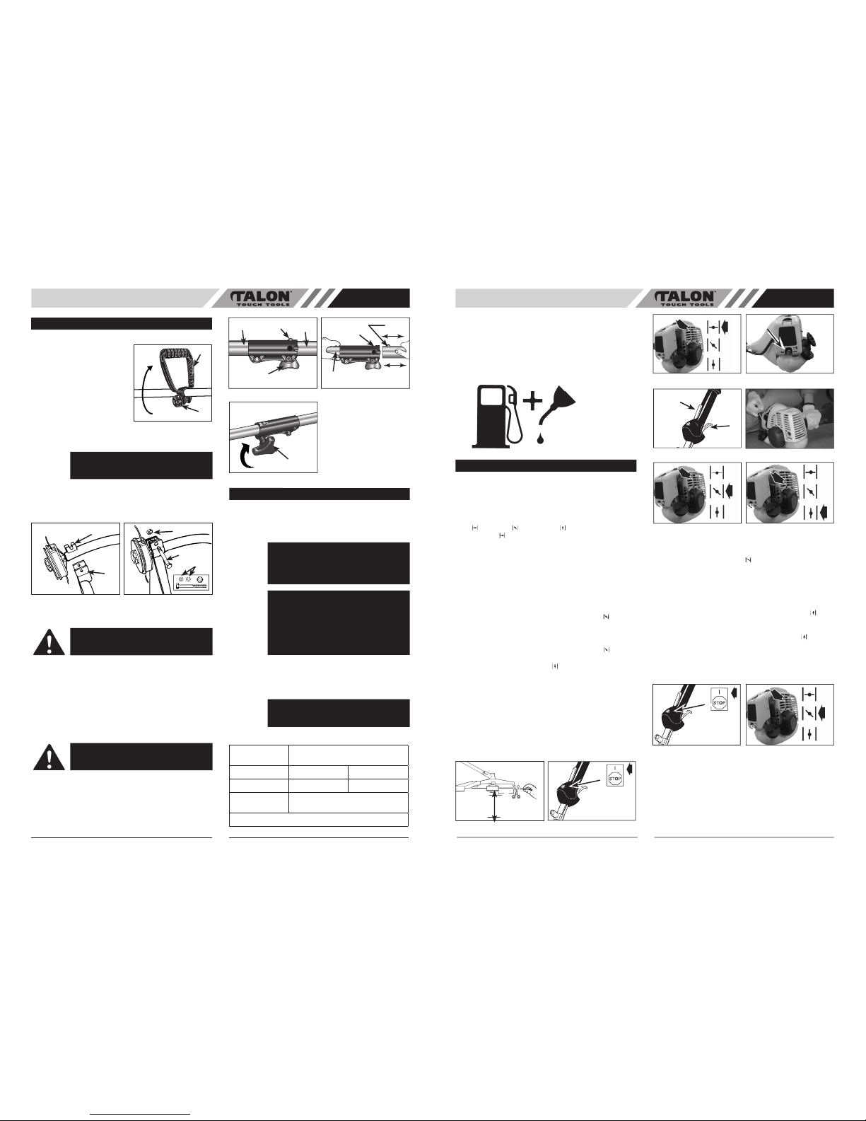
SAFETY FEATURES
3 DEBRIS SHIELD must be installed to prevent debris from being thrown at the operator and prevent the string from
extending longer than necessary.
14 MUFFLER SHIELD helps prevent hands, body and/or combustible materials from making contact with a hot muffler.
1. LINEHEAD
2. TRIMMING LINE
3. DEBRIS SHIELD*
4. DRIVE SHAFT ASSEMBLY
5. HANDLE
6. THROTTLE TRIGGER
7. IGNITION OFF SWITCH
8. SAFETY TRIGGER
9. CHOKE LEVER
10. STARTER ROPE HOUSING
11. FUEL TANK
12. AIR FILTER COVER
13. STARTER HANDLE
14. MUFFLER SHIELD
15. PRIMER BULB
16. DEBRIS SHIELD NUT & BOLT & WASHER*
17. UNIVERSAL COUPLING
*Supplied in User Kit
NOTE: DO NOT use blades on these models.
GENERAL IDENTIFICATION
1
2
3
4
5
6
16
8
7
17
5
13
9
10
11
12
14
15
Page 4
7
AU
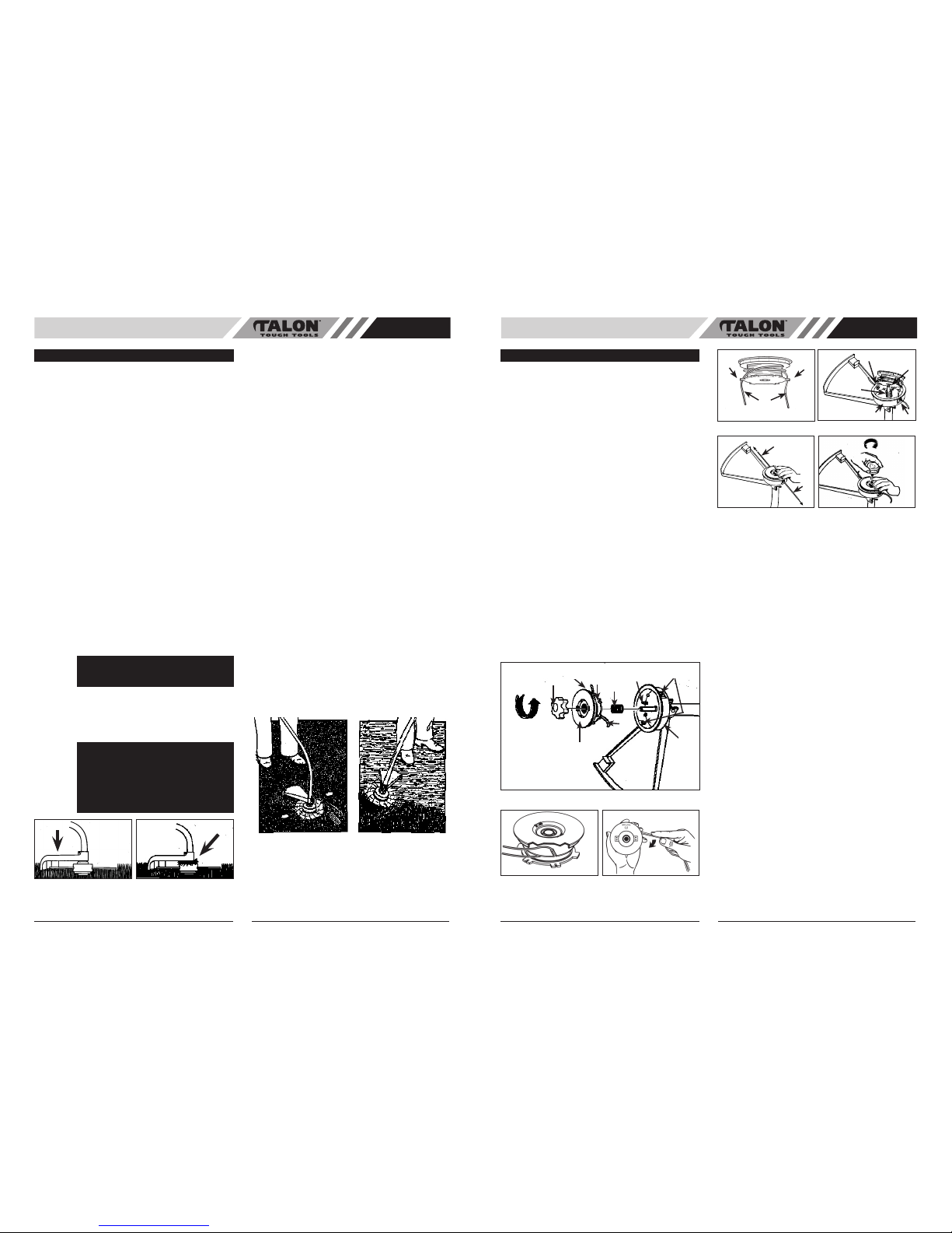
• HANDLE ASSEMBLY
NOTE: The Handle is attached
to the shaft but has beened
turned under for ease of pack
-
ing.
1. Loosen adjustment knob
(A) and rotate handle (B)
to top of shaft. Position
handle follow the arrow.
See Fig. 1
2. Tighten adjustment knob
securely.
• DEBRIS SHIELD
Shield fits snug on shaft. Some effort may be required.
1. Seat shield (B) onto shaft bracket (C).
2. Insert washers (D) onto bolt.
3. Insert bolt (E) and nut (F), tighten securely.
• INSTALLING ATTACHMENTS
NOTE: To make installing or removing attachments easi-
er, place the unit on the ground or on a work bench.
1. Turn the knob (A) counterclockwise to loosen (Fig.
3A).
2. While firmly holding the attachment (B), push it
straight into the Quick-Change coupling (C) until the
release button (D) appears in the primary hole (E)
(Fig. 3B)
3. Turn the knob (A) clockwise to tighten. (Fig. 3C)
All attachments are designed to be used in the primary
hole unless otherwise indicated in the specific attachment
operators manual. If the incorrect hole is used, it could
result in injury, or damage to the unit.
• FUEL
Use regular grade unleaded gasoline mixed with Talon
25:1 custom 2-cycle engine oil for best results. Use mixing
ratios in FUEL MIXING TABLE.
• MIXING FUEL
Add the oil to an approved fuel container followed by the
gasoline to allow incoming gasoline to mix with oil. Shake
the container to ensure thorough mix.
• FUEL MIXING TABLE
GASOLINE Talon 25:1 Ratio
Custom Lubricant
5 Liters
6.7 oz. 200ml (cc)
1 Imp. Gal
. 6.1 oz. 180ml (cc)
Mixing
Procedure
25 Parts Gasoline
to 1 part Lubricant
1ml = 1cc
ASSEMBLY INSTRUCTIONS
B
Fig. 1
A
WARNING:
The debr is shiel d must be
installed (Fig. 2) to properly dispense trim
-
ming line and protect operator.
B
C
Fig. 2A
Fig. 2B
F
E
D
WARNING:
To avoid serious personal injury,
shut unit off before removing or installing
attachment.
CAUTION:
The release button must be in the
primary hole and the knob securely tightened
before operating this unit.
A
Fig. 3C
Fig. 3A
Fig. 3B
A
B
D
C
D
E
D
FUEL AND LUBRICATION
WARNING:
Never use straight gasoline in
your unit. This will cause permanent engine
damage and void the manufacturer’s warran
ty for that product. Never use a fuel mixture
that has been stored for over 90 days.
WARNING:
If 2-cycle lubricant other tha n
Talon Custom Lubricant is to be used, it must
be a premium grade oil for 2-cycle air cooled
engines mixed at a 25:1 ratio. Do not use
any 2-cycle oil product with a recommended
mixing ratio of 100:1. If insufficient lubrication
is the cause of engine damage, it voids the
manufacturer’s engine warranty.
WARNING: Lack of lubrication voids engine
warranty. Gasolilne and oil must be mixed
at 25:1.
8
• RECOMMENDED FUELS
Some conventional gasolines are being blended with
oxygenates such as alcohol or an ether compound to
meet clean air standards. Your Talon engine is designed
to operate satisfactorily on any gasoline intended for auto
-
motive use including oxygenated gasolines.
• FUEL AND LUBRICATION
• STARTING A COLD ENGINE
NOTE: To minimize load on engine during starting and
warm-up, trim excess cutter line to 13cm (Fig. 4A).
1. Move ignition switch to the “RUN (I)” position (Fig.
9B).
2. Your unit is designed with a 3 position choke: CHOKE
“ ”, START “ ”, and RUN “ ”. Move choke lever to
CHOKE “
” position (Fig. 4B).
3. Prime the carburetor. Pump the primer bulb (D) 10
times (Fig. 4C).
4. Grip handle firmly – depress safety trigger (E) &
throttle trigger (F) to the FULL THROTTLE position
(Fig. 4D).
5. AT33581 - Pull starter rope out a short way until
resistance is felt (approximately 100mm) (Fig. 4E). A
smooth rapid pull is required for a strong spark. Pull
starter rope briskly 4 times.
6. AT33582 - Move choke lever to START “
” position
(Fig. 4F).
7. Pull starter rope again 4 times while trigger is in the
full throttle position (Fig. 4G)
8. Once engine starts, leave in the START “
” position
for 10 seconds.
9. Move the choke to RUN “
” position (Fig. 4H).
10. If engine fails to start, repeat steps 1 through 7.
NOTE: If engine fails to start after repeated attempts, refer
to Troubleshooting section.
NOTE: Always pull starter rope straight out. Pulling starter
at an angle will cause rope to rub against the eyelet. This
friction will cause the rope to fray and wear more quickly.
Always hold starter handle when rope retracts. Never
allow rope to snap back from extended position. This
could cause rope to snag or fray and also damage the
starter assembly.
• WARM ENGINE START
1. Move ignition switch to the “RUN” position (Fig. 5A).
2. Place choke in START “
” position (Fig. 5B).
3. Grasp throttle handle firmly, squeeze throttle trigger to
FULL position.
4. Pull starter rope briskly until engine starts, but no
more than 6 times. Keep throttle at FULL position until
engine runs smoothly.
5. If engine does not start, place choke in RUN “
” position and pull starter rope 5 more times. If engine still
does not start it is probably flooded. Wait 5 minutes
and repeat procedure with choke in RUN “
” position
and throttle full open.
• TO STOP ENGINE
Release throttle trigger. Let engine return to idle. Push and
hold ignition stop switch until engine stops.
Gasoline and
Oil Mix 25:1
OPERATING INSTRUCTIONS
AU
Fig. 4C Fig. 4D
Fig. 4E
Fig. 4F
Fig. 4G
Fig. 4H
Fig. 4A Fig. 4B
13cm
For Line Head
0-300mm
For blade
100-400mm
Fig. 5B
Fig. 5A
A
D
E
F
A
Page 5
AU
9
• ADDITIONAL SAFETY PRECAUTIONS
Before operating your unit, review ALL SAFETY
PRECAUTIONS in this manual.
WARNING / CAUTION
• IF UNFAMILIAR WITH TRIMMING techniques, practice
the procedures with ENGINE in “OFF” position.
• ALWAYS CLEAR WORK area of debris such as cans,
bottles, rocks, etc. Striking objects can cause serious
injury to operator or bystanders and also damage
equipment. If an object is accidentally hit, immediately
TURN ENGINE OFF and examine equipment. Never
operate unit with damaged or defective equipment.
• ALWAYS TRIM OR CUT AT HIGH ENGINE SPEEDS.
Do not run engine slowly at start or during trimming
operations.
• DO NOT use equipment for purpose s other than
trimming or mowing weeds.
• NEVER rais e linehead abo ve knee heigh t during
operation.
• DO NOT operate unit with other people or animals
in the immediate vicinity. Allow a minimum of 50 feet
(15 meters) between operator and other people and
animals when trimming or mowing.
• Allow a distance of 100 feet (30 meters) between
operator and other people and animals when SCALPING
with linehead cutter.
• IF OPERATING UNIT ON A SLOPE, stand below the
cutting attachment. DO NOT OPERATE on a slope or
hilly incline if there is the slightest chance of slipping or
losing your footing.
• LINEHEAD LINE RELEASE
To release fresh line, run engine at full throttle and “bump”
linehead against lawn. Line will automatically release. The
knife in debris shield will trim excess line (Fig. 6A).
• TRIMMING PROCEDURES
When properly equipped with a debris shield and linehead,
your unit will trim unsightly weeds and tall grass in those
hard-to-reach areas - along fences, walls, foundations and
around trees. It can also be used for scalping to remove
vegetation down to the ground for easier preparation of a
garden or to clean out a particular area.
NOTE: Even with care, trimming around foundations, brick
or stone walls, curves, etc., will result in above normal
line wear.
TRIMMING / MOWING
Swing trimmer with a sickle-like motion from side to side.
Do not tilt the linehead during the procedure. Test area
to be trimmed for proper cutting height. Keep linehead at
same level for even depth of cut (Fig. 7A).
CLOSER TRIMMING
Position trimmer straight ahead with a slight tilt so bottom
of linehead is above ground level and line contact occurs
at proper cutting point. Always cut away from operator. Do
not pull trimmer in toward operator.
FENCE / FOUNDATION TRIMMING
Approach trimming around chain link fences, picket fenc
es, rock walls and foundations slowly to cut close without
whipping line against the barrier. If the line comes in con
tact with rock, brick walls, or foundations, it will break or
fray. If line snags fencing, it will snap off.
TRIMMING AROUND TREES
Trim around tree trunks with a slow approach so line does
not contact bark. Walk around the tree trimming from left
to right. Approach grass or weeds with the tip of the line
and tilt linehead slightly forward.
SCALPING
Scalping refers to removal of all vegetation down to the
ground. To do this, tilt the linehead to about a 30 degree
angle to the left. By adjusting the handle you will have
better control during this operation. Do not attempt this
procedure if there is any chance flying debris could injure
operator, other people or cause damage to property. (Fig.
7B)
TRIMMING INSTRUCTIONS
WARNING:
DO NOT use steel wire or plastic-
coated steel wire of any kind with your line
-
head. Serious operator injury can result.
CAUTION: Periodically remove weed wrap
to prevent overheating the drive shaft. Weed
wrap occurs when strands of weed become
entangled aroun d the shaft be neath the
debris shield (Fig. 6B). This condition pre
vents the shaft from being properly cooled.
Remove weed w rap with scre wdriver or
similar device.
Fig. 6A
Fig. 6B
BUMP
Fig. 7A
Fig. 7B
• REPLACING TRIMMING - LINE STANDARD
HEAD
1. Turn knob (A) COUNTERCLOCKWISE and remove
(Fig. 8A). User knob spanner supplied.
2. Remove spool (B) and spring (C) from spindle (D).
3. Remove any remaining cutter line (H).
4. Double a 14' (4.3m) length of .080" (2mm) cutter line.
Place the looped center in one of the slots of the
spool divider (Fig. 8B).
5. Wind cutter line clockwise as shown in illustration
(Fig. 8C), keeping tension, with each half separated
by the spool divider. Wind to within 6" (15cm) of the
ends.
6. Lock each end of line (H) into a slot (F) on opposite
sides of the spool (Fig. 8D).
7. Install the spring (C) over the spindle (D). Insert each
end of the line through an eyelet (G) in the housing
(E) (Fig. 8E).
8. Lower the spool into the housing (E) while feeding the
line through the eyelets (G). Ensure the spring seats
itself into the spool (Fig. 8E).
9. Once the spool is in place, apply pressure on the spool
compressing the spring. Pull each end of the line (H)
sharply to unlock the line from the slots (Fig. 8F).
10. Continue to apply pressure to the spool until the
knob can be threaded CLOCKWISE onto the spindle.
Tighten the knob securely by hand only (Fig. 8G).
11. Trim the excess line to approximately 5" (13cm).
This will minimize load on engine during starting and
warm-up (Fig. 4A).
•
10
AU
MAINTENANCE INSTRUCTIONS
Fig. 8B Fig. 8C
A
B
C
D
E
F
H
H
G
Fig. 8A
A. KNOB
B. SPOOL
C. SPRING
D. SPINDLE
E. HOUSING
F. SLOTS
G. EYELETS
H. CUTTER LINE
Fig. 8D Fig. 8E
H
F
F
Fig. 8F Fig. 8G
H
H
G
D
G
E
C
Page 6
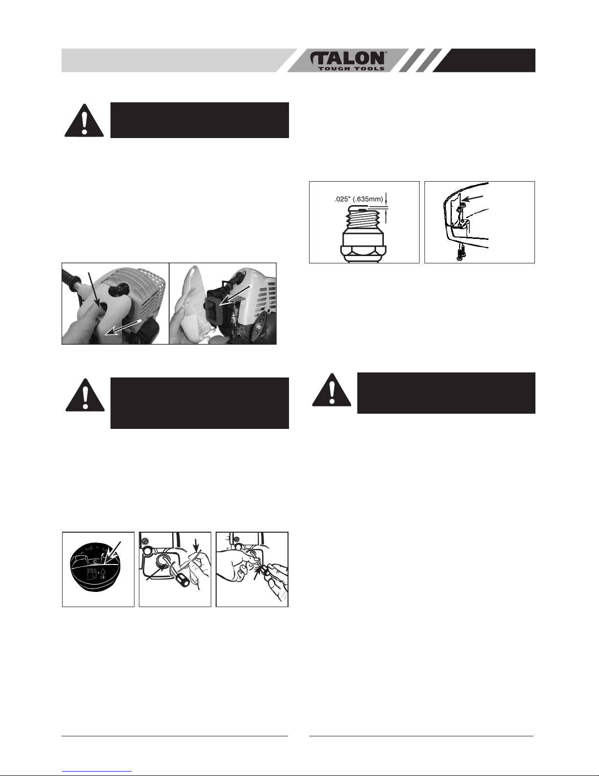
• AIR FILTER
To Clean Air Filter:
1. Press down on tab (A) holding air filter cover in place,
remove cover (B) and lift filter (C) from air box. (Fig.
9)
2. Wash filter in soap and water. DO NOT USE
GASOLINE!
3. Air dry filter.
4. Reinstall filter.
NOTE: Replace filter if frayed, torn, damaged or unable
to be cleaned.
• FUEL CAP / FUEL FILTER
NOTE:Completely remove fuel cap (A) from fuel tank.
(Fig. 10A)
1. Lift fuel line and filter (B) out of tank. A steel wire (C)
with a hook or a paper clip works well (Fig. 10B).
2. Pull off with a twisting motion (Fig. 10C).
3. Replace fuel filter (D).
NOTE: Never operate the trimmer without the fuel filter.
Internal engine damage could result!
• CARBURETOR ADJUSTMENT
The carburetor was pre-set at the factory for optimum
performance. If further adjustments are necessary, please
take your unit to the nearest Authorized Service Center.
• SPARK PLUG
1. Spark plug gap = .025" (.635mm) (Fig. 12).
2. Torque to 105 to 130 inch pounds (12 to 15 N•m).
Connect spark plug boot.
• DEBRIS SHIELD KNIFE SHARPENING
1. Remove cutter knife (A) from debris shield (B) (Fig.
13).
2. Place knife in a bench vise. Sharpen knife using a
flat file, being careful to maintain the angle of cutting
edge. File in one direction only.
• STORING A UNIT
1. Perform all the general maintenance recommended
in the Maintenance Section of your User Manual.
2. Clean exterior of engine, drive shaft assembly, debris
shield and linehead.
3. Drain fuel from the fuel tank.
4. After fuel is drained, start engine.
5. Run engine at idle until unit stops. This will purge the
carburetor of fuel.
6. Allow engine to cool (approx. 5 minutes).
7. Using a spark plug wrench, remove the spark plug.
8. Pour 1 teaspoon of clean 2-cycle oil into the
combustion chamber. Pull starter rope slowly several
times to coat internal components. Replace spark
plug.
9. Store unit in a cool, dry place away from any source
of ignition such as an oil burner, water heater, etc.
10. Put the sleeve on when not in use or in transportation.
• REMOVING A UNIT FROM STORAGE
1. Remove spark plug.
2. Pull starter rope briskly to clear excess oil from combustion chamber.
3. Clean and gap spark plug or install a new spark plug
with proper gap.
4. Prepare unit for operation.
5. Fill fuel tank with proper fuel / oil mixture. See Fuel
and Lubrication Section.
11
AU
CAUTION: NEVER operate trimmer without
the air filter. The air filter must be kept clean.
If it becomes damaged, install a new filter.
CAUTION: Remove fuel from unit and store
in approved container before starting this
procedure. Open fuel cap slowly to release
any pressure which may have formed in
fuel tank.
A
Fig. 10A Fig. 10B
D
Fig. 10C
C
B
Fig. 12 Fig. 13
A
B
WARNING: Failure to follow these steps may
cause varnish to form in the carburetor and
difficult starting or permanent damage follow
-
ing storage.
Fig. 9
A
B
C
 Loading...