

Page 1

Model No. AC31A1
USER MANUAL
Petrol Chain Saws
18.9Þ
CKA
SAFETY OPERATION MAINTENANCE
WARNING • PLEASE READ
Beware of kickback. Hold chain saw firmly with both hands when using. For your own safety, please
read and follow the safety precautions in this manual before attempting to operate your chain saw.
Improper use can cause serious injury.
This product has been tested at a computed kickback angle (CKA) of no greater than 18.9 degrees.
9096-31A103(2) © Jenn Feng Inc., 1975, 2002
1
GENERAL SAFETY RULES
GB
WARNING! When using gas tools, basic safety precautions, including the following, should always be followed to
reduce the risk of serious personal injury and/or damage to the unit.
Read all these instructions before operating this product and save these instructions.
1. DO NOT operate a chain saw with one hand! Serious
injury to the operator, helpers, bystanders, or any
combination of these persons may result from onehanded operation. A chain saw is intended for twohanded use.
2. DO NOT operate a chain saw when you are fatigued.
3. Use safety footwear, snug-fitting clothing, protective
gloves, and eye, hearing and head protection
devices.
4. Use caution when handling fuel. Move the chain saw
at least 10 feet (3m) from the fueling point before
starting the engine.
5. DO NOT allow other persons to be near when starting or cutting with the chain saw. Keep bystanders
and animals out of the work area.
6. DO NOT start cutting until you have a clear work
area, secure footing, and a planned retreat path from
the falling tree.
7. Keep all parts of your body away from the saw chain
when the engine is running.
8. Before you start the engine, make sure that the saw
chain is not contacting anything.
9. Carry the chain saw with the engine stopped, the
guide bar and saw chain to the rear, and the muffler
away from your body.
10. DO NOT operate a chain saw that is damaged,
improperly adjusted, or not completely and securely
assembled. Be sure that the saw chain stops moving
when the throttle control trigger is released.
11. Shut off the engine before setting the chain saw
down.
12. Use extreme caution when cutting small size brush
and saplings because slender material may catch the
saw chain and be whipped toward you or pull you off
balance.
13. When cutting a limb that is under tension, be alert for
springback so that you will not be struck when the
tension in the wood fibers is released.
14. Keep the handles dry, clean, and free of oil or fuel
mixture.
15. Operate the chain saw only in well-ventilated areas.
16. DO NOT operate a chain saw in a tree unless you
have been specifically trained to do so.
17. All chain saw service, other than the items listed in
the user manual safety and maintenance instructions,
should be performed by competent chain saw service
personnel.
18. When transporting your chain saw, use the appropriate guide bar scabbard (when supplied).
19. DO NOT operate your chain saw near or around
flammable liquids or gases whether in or out of doors.
An explosion and/or fire may result.
20. Do not tank fuel, oil or lubrication when the engine of
chain saw is running.
21. USE THE RIGHT TOOL: Cut wood only. Do not use
the chain saw for purposes for which it was not
intended. For example, do not use the chain saw for
cutting plastic, masonry, or nonbuilding materials.
NOTE: This appendix is intended primarily for the consumer or occasional user. These models are intended for
infrequent use by homeowners, cottagers, and campers,
and for such general applications as clearing, pruning,
cutting firewood, etc. They are not intended for prolonged
use. If the intended use involves prolonged periods of
operation, this may cause circulatory problems in the
user’s hands due to vibration. It may be appropriate to use
a saw having an anti-vibration feature such as the models
covered in this manual with the suffix Anti-Vibration.
Kickback may occur when the nose or tip of the guide bar
touches an object, or when the wood closes in and pinches the saw chain in the cut. If the bar tip contacts, it may
cause a lightning-fast reverse reaction, kicking the guide
bar up and back towards the operator. Pinching the saw
chain along the top of the guide bar may push the guide
bar rapidly back towards the operator. Either of these
reactions may cause you to lose control of the saw, which
could result in serious personal injury. Do not rely exclusively upon the safety devices built into your saw. As a
chain saw user, you should take several steps to keep
your cutting jobs free from accident or injury.
1. With a basic understanding of kickback, you can
reduce or eliminate the element of surprise. Sudden
surprise contributes to accidents.
2. Keep a good firm grip on the saw with both hands,
the right hand on the rear handle, and the left hand
on the front handle, when the engine is running. Use
a firm grip with thumbs and fingers encircling the
chain saw handles. A firm grip will help you reduce
kickback and maintain control of the saw. Don’t let
go.
3. Make sure that the area in which you are cutting is
free from obstructions. Do not let the nose of the
guide bar contact a log, branch, or any other obstruction which could be hit while you are operating the
saw.
4. Cut at high engine speeds.
5. Do not overreach or cut above shoulder height.
6. Follow manufacturer’s sharpening and maintenance
instructions for the saw chain.
7. Only use replacement bars and chains specified by
the manufacturer or the equivalent.
NOTE: Low-kickback saw chain is chain that has met the
Meaning of symbols marked on the product
Read the user manual before using the machine
Wear safety goggles to protect your eyes
Wear ear protector to protect against noise
Wear dust mask to protect against dust
Wear glove to protect your hands
Wear safety boots to protect against electric shock
KICKBACK SAFETY PRECAUTIONS
Page 2
3
GB
2
GB
Your Talon Chain Saw is provided with a safety label
located on the chain brake lever/hand guard. This label,
along with the safety instructions on these pages, should
be carefully read before attempting to operate this unit.
• HOW TO READ SYMBOLS AND COLORS (FIG. 1)
GREEN RECOMMENDED
Recommended cutting procedure.
WARNING
1. Beware of kick back.
2. Do not attempt to hold saw
with one hand.
3. Avoid bar nose contact.
RECOMMENDED
4. Hold Saw properly with both
hands.
• DANGER! BEWARE OF KICKBACK!
KICKBACK may occur when the NOSE or TIP of the
guide bar touches an object, or when wood closes in and
pinches the saw chain in the cut.
Tip contact in some cases may cause a lightning-fast
reverse reaction, kicking the guide bar up and back
toward the operator.
PINCHING the saw chain along the BOTTOM of the
guide bar may PULL the saw forward away from the
operator. PINCHING the saw chain along the TOP of the
guide bar may PUSH the guide bar rapidly back toward
the operator.
Any of these reactions may cause you to lose control of
the saw, which could result in serious personal injury.
IMPORTANT SAFETY
WARNING: RED Used to warn that an
unsafe procedure should not be performed.
1
2
3
4
Fig. 1
WARNING: Kickback can lead to dangerous
loss of control of the chain saw and result in
serious or fatal injury to the saw operator or to
anyone standing close by. Always be alert.
Rotational kickback and pinch-kickback are
major chain saw operational dangers and the
leading cause of most accidents.
Fig. 2A
Fig. 2B
A
A
B
A
A
B
C
BEWARE OF:
ROTATIONAL KICKBACK THE PUSH
(Fig. 2A) (PINCH KICKBACK)
AND PULL REACTIONS
(Fig. 2B)
A = Kickback path A = Pull
B = Kickback reaction zone B = Solid objects
C = Push
NOTE: Not all models available in all countries:
Model No. . . . . . . . . . . . . . . . . . . . . . . . .AC31A116-35S . . . . .AC31A116-38S . . . .AC31A140S . . . . . .AC31A118-38S
Engine Disp;acement . . . . . . . . . . . . . . . .35cc . . . . . . . . . . . . . .38cc . . . . . . . . . . . . .38cc . . . . . . . . . . . .38cc
Cutting Length . . . . . . . . . . . . . . . . . . . . .16” (40cm) . . . . . . . . .16” (40cm) . . . . . . . .16” (40cm) . . . . . . .18” (45cm)
Chain Pitch . . . . . . . . . . . . . . . . . . . . . . .3/8” . . . . . . . . . . . . . .3/8” . . . . . . . . . . . . . .3/8” . . . . . . . . . . . . .3/8”
Chain Gauge . . . . . . . . . . . . . . . . . . . . . .1.3mm (0.05”) . . . . . .1.3mm (0.05”) . . . . . .1.3mm (0.05”) . . . . .1.3mm (0.05”)
Idle Speed . . . . . . . . . . . . . . . . . . . . . . . .
2,800-3,300 R.P.M. . . .2,800-3,300 R.P.M..2,800-3,300 R.P.M. . . .2,800-3,300 R.P.M.
Speed in Max power . . . . . . . . . . . . . . . .8,000 R.P.M. . . . . . . .8,000 R.P.M. . . . . . .8,000 R.P.M. . . . . .8,000 R.P.M.
Fuel Capacity . . . . . . . . . . . . . . . . . . . . . .296CC (10 oz) . . . . . .296CC (10 oz) . . . . .296CC (10 oz) . . . .296CC (10 oz)
Oil Capacity . . . . . . . . . . . . . . . . . . . . . . .180CC (6.1 oz) . . . . .180CC (6.1 oz) . . . . .180CC (6.1 oz) . . . .180CC (6.1 oz)
Anti Vibration . . . . . . . . . . . . . . . . . . . . . .Y . . . . . . . . . . . . . . . .Y . . . . . . . . . . . . . . . .Y . . . . . . . . . . . . . . .Y
Sprocket Tip Bar . . . . . . . . . . . . . . . . . . .9 Teeth . . . . . . . . . . .9 Teeth . . . . . . . . . . .9 Teeth . . . . . . . . . .9 Teeth
Chain Brake . . . . . . . . . . . . . . . . . . . . . . .Y . . . . . . . . . . . . . . . .Y . . . . . . . . . . . . . . . .Y . . . . . . . . . . . . . . .Y
Clutch . . . . . . . . . . . . . . . . . . . . . . . . . . . .Y . . . . . . . . . . . . . . . .Y . . . . . . . . . . . . . . . .Y . . . . . . . . . . . . . . .Y
Automatic Chain Oiler . . . . . . . . . . . . . . .Y . . . . . . . . . . . . . . . .Y . . . . . . . . . . . . . . . .Y . . . . . . . . . . . . . . .Y
Lower Kick Back Chain . . . . . . . . . . . . . .Y . . . . . . . . . . . . . . . .Y . . . . . . . . . . . . . . . .Y . . . . . . . . . . . . . . .Y
Net Weight
(Without guide bar and chain) .5.1 Kg . . . . . . . . . . . .5.1 Kg . . . . . . . . . . . .5.1 Kg . . . . . . . . . . .5.1 Kg
Net Weight . . . . . . . . . . . . . . . . . . . . . . . .5.88 Kg . . . . . . . . . . .5.88 Kg . . . . . . . . . . .5.88 Kg . . . . . . . . . .6.01 Kg
Sound pressure level . . . . . . . . . . . . . . . .97.6 dB(A) . . . . . . . . .97.6 dB(A) . . . . . . . .97.6 dB(A) . . . . . . .97.6 dB(A)
Sound power level . . . . . . . . . . . . . . . . . .103 dB(A) . . . . . . . . .103 dB(A) . . . . . . . . .103 dB(A) . . . . . . . .103 dB(A)
Mean braking time at racing speed . . . .0.07s . . . . . . . . . . . . .0.07s . . . . . . . . . . . .0.07s . . . . . . . . . . .0.07s
Vibration . . . . . . . . . . . . . . . . . . . . . . . . . .10.2 m/s
2
. . . . . . . . . .10.2 m/s2 . . . . . . . . .10.2 m/s2 . . . . . . . .10.2 m/s
2
Fuel Consumption . . . . . . . . . . . . . . . . . .1.5 l/h . . . . . . . . . . . . .1.5 l/h . . . . . . . . . . . .1.5 l/h . . . . . . . . . . .1.5 l/h
SPECIFICATIONS
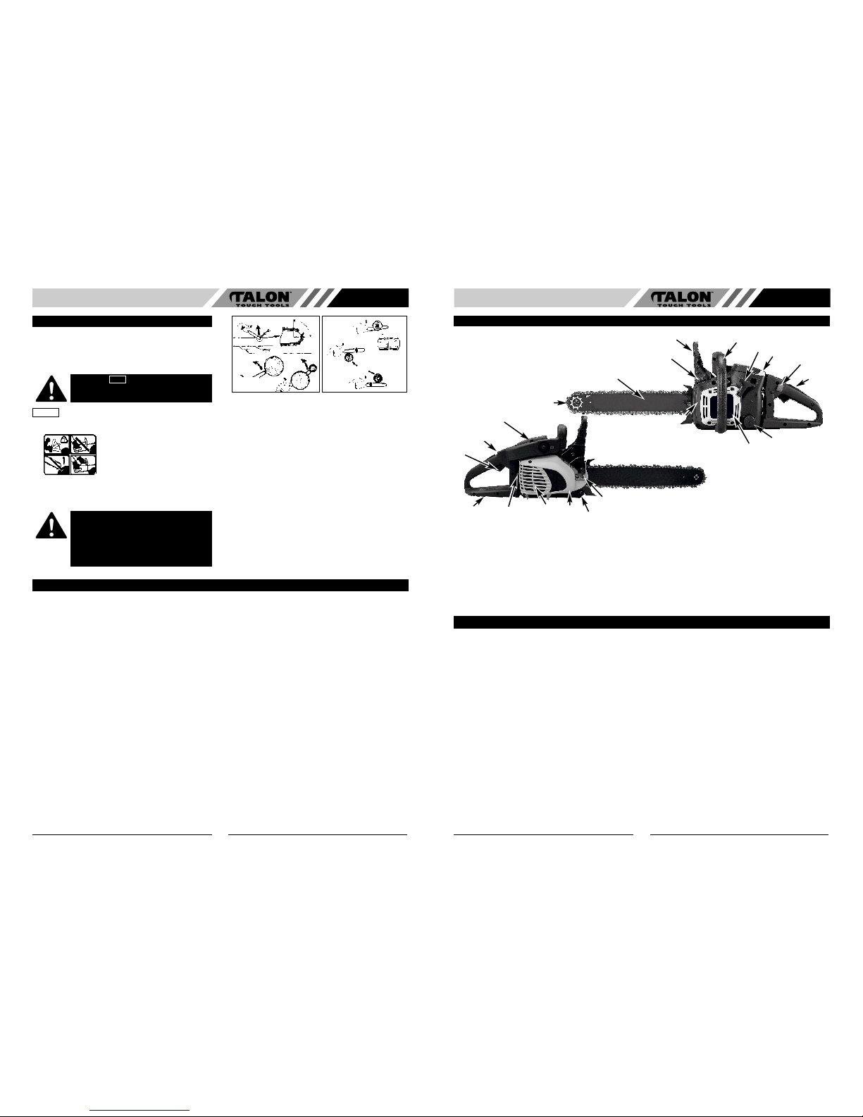
1. Guide Bar
2. Saw chain
3. Saw Chain Adjustment Screw
4. Spark Arrester Screen
5. Chain Brake Lever / Hand
Guard
6. Front Handle
7. Starter Handle
8. Spark Plug
9. Air Cleaner Cover
10. Stop Switch
11. Safety Trigger
12. Oil Tank cap
13. Starter Cover
14. Fuel Tank Cap
15. Rear Handle / Boot Loop
16. Throttle Latch
17. Choke Lever
18. Bar Retaining Nuts
19. Throttle Trigger
20. Chain Catcher
21. Muffler Shield/Clutch Cover
GENERAL INFORMATION
3
2
10
6
7
17
11
12
13
14
1
9
16
15
8
4
20
18
2 LOW KICKBACK SAW CHAIN helps significantly
reduce kickback, or the intensity of kickback, due to
specially designed depth gauges and guard links.
4 SPARK ARRESTER SCREEN retains carbon and
other flammable particles over 0.023 inches (0.6mm)
in size from engine exhaust flow. Compliance with
local, state and federal laws and/or regulations governing the use of a spark arrester screen is the user’s
responsibility. See Safety Precautions for additional
information.
5 CHAIN BRAKE LEVER / HAND GUARD protects the
operator’s left hand in the event it slips off the front
handle while saw is running.
5 CHAIN BRAKE is a safety feature designed to
reduce the possibility of injury due to kickback by
stopping a moving saw chain in milliseconds. It is
activated by the CHAIN BRAKE lever.
10 STOP SWITCH immediately stops the engine when
tripped. Stop switch must be pushed to ON position
to start or restart engine.
11 SAFETY TRIGGER prevents accidental acceleration
of the engine. Throttle trigger (19) cannot be
squeezed unless the safety latch is depressed.
20 CHAIN CATCHER reduces the danger of injury in
the event saw chain breaks or derails during
operation. The chain catcher is designed to intercept
a whipping chain.
21 MUFFLER SHIELD / CLUTCH COVER helps pre-
vent hands and combustible materials from making
contact with a hot muffler.
NOTE: Study your saw and be familiar with its parts.
SAFETY FEATURES
Numbers preceding the descriptions correspond with the numbers on preceding page to help you locate the safety
feature.
5
19
21
Page 3
5
GB
4
GB
• TOOLS FOR ASSEMBLY
You will need these tools to assemble your chain saw:
1. Combination wrench-screwdriver (contained in your
user’s kit).
2. Heavy duty work gloves (user supplied).
• ASSEMBLY REQUIREMENTS
Your new chain saw will require adjustment of chain,
filling the fuel tank with correct fuel mixture and filling the
oil tank with lubricating oil before the unit is ready for
operation.
Read the entire user manual before attempting to
operate your unit. Pay particular attention to all safety
precautions.
Your user manual is both a reference guide and handbook provided to furnish you with general information to
assemble, operate and maintain your saw.
• GUIDE BAR / SAW CHAIN / CLUTCH COVER
INSTALLATION
TO INSTALL GUIDE BAR:
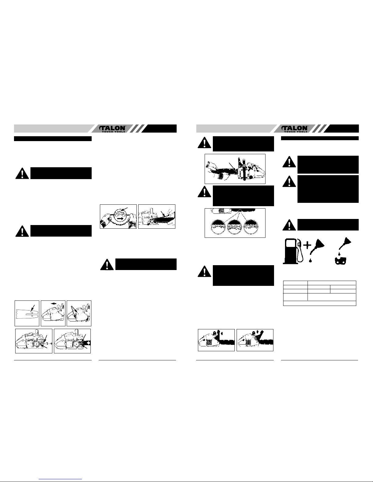
To ensure the bar and chain receive oil, ONLY USE
THE ORIGINAL STYLE BAR with the oil passage hole
(A) as illustrated below (Fig. 3A).
1. Make sure the Chain brake lever is pulled back into
the DISENGAGED position (Fig. 3B)
2. Remove the 2 bar retaining nuts (B). Loosen the 2
screws at the rear of the clutch cover (C). Remove
the cover (Fig. 3C).
3. Using a screwdriver, run the adjustment screw (D)
COUNTERCLOCKWISE until the TANG (E) (projecting prong) is to the end of its travel toward the
clutch drum and sprocket (Fig. 3D).
4. Place the slotted end of the guide bar over the 2 bar
bolts (F). Position the bar so that the adjustment
TANG fits into the lower hole (G) on the guide bar
(Fig. 3E).
TO INSTALL SAW CHAIN:
1. Spread chain out in a loop with cutting edges (A)
pointing CLOCKWISE around loop (Fig. 4A).
2. Slip the chain around the sprocket (B) behind the
clutch (C). Make sure the links fit between the
sprocket teeth (Fig. 4B).
3. Guide the drive links into the groove (D) and around
the end of the bar (Fig. 4B).
NOTE: The saw chain may droop slightly on the lower
part of bar. This is normal.
4. Install the clutch cover and tighten the 2 screws.
Make sure the chain does not slip off of the bar.
Install the 2 nuts hand tight and follow tension
adjustment instructions in Section SAW CHAIN
TENSION ADJUSTMENT.
NOTE: The guide bar retaining nuts are installed only
hand tight at this point because saw chain adjustment is
required. Follow instructions in Section SAW CHAIN
TENSION ADJUSTMENT.
• SAW CHAIN TENSION ADJUSTMENT
Proper tension of saw chain is extremely important and
must be checked before starting, as well as during any
cutting operation.
Taking the time to make needed adjustments to the saw
chain will result in improved cutting performance and
prolonged chain life.
TO ADJUST SAW CHAIN:
1. Hold nose of guide bar up and turn adjustment screw
(D) CLOCKWISE to increase chain tension. Turning
screw COUNTERCLOCKWISE will decrease amount
of tension on chain. Ensure the chain fits snugly all
the way around the guide bar (Fig. 5).
2. After making adjustment, and while still holding nose
of bar in the uppermost position, tighten the bar
retaining nuts securely. Chain has proper tension
when it has a snug fit all around and can be pulled
around by gloved hand.
NOTE: If chain is difficult to rotate on guide bar or if it
binds, too much tension has been applied. This requires
minor adjustment as follows:
A. Loosen the 2 bar retaining nuts so they are finger
tight. Decrease tension by turning the bar
adjustment screw COUNTERCLOCKWISE slowly.
Move chain back and forth on bar. Continue to
adjust until chain rotates freely, but fits snugly.
Increase tension by turning bar adjustment screw
CLOCKWISE.
B. When saw chain has proper tension, hold nose of
bar in the uppermost position and tighten the 2 bar
retaining nuts securely.
ASSEMBLY INSTRUCTIONS
WARNING:
DO NOT start saw engine until
unit is properly prepared.
WARNING: Always wear protective gloves
when handling chain.
A
Fig. 3D
Fig. 3B
D
E
G
F
Fig. 3A
Fig. 3B
B
C
Fig. 3C
A
B
C
D
WARNING: Always wear heavy duty gloves
when handling saw chain or making saw
chain adjustments.
• CHAIN BRAKE MECHANICAL TEST
Your chain saw is equipped with a Chain brake that
reduces possibility of injury due to kickback. The brake is
activated if pressure is applied against brake lever when,
as in the event of kickback, operator’s hand strikes the
lever. When the brake is actuated, chain movement
stops abruptly.
TO TEST CHAIN BRAKE:
1. The Chain brake is DISENGAGED (chain can move)
when BRAKE LEVER IS PULLED BACK AND
LOCKED (Fig. 7A).
2. The Chain brake is ENGAGED (chain is stopped)
when brake lever is in forward position. You should
not be able to move chain (Fig. 7B).
NOTE: The brake lever should snap into both positions.
If strong resistance is felt, or lever does not move into
either position, do not use your saw. Take it immediately
to a professional Service Center for repair.
• FUEL
Use regular grade unleaded gasoline mixed with 2-cycle
engine oil in 25:1 ratio for best results. Use mixing
ratios in Section FUEL MIXING TABLE.
• MIXING FUEL
Mix fuel with Talon brand 2 cycle oil in an approved
container. Use mixing table for correct ratio of fuel to oil.
Shake container to ensure thorough mix.
• FUEL AND LUBRICATION
• FUEL MIXING TABLE
• RECOMMENDED FUELS
Some conventional gasolines are being blended with
oxygenates such as alcohol or an ether compound to
meet clean air standards. Your Talon engine is designed
to operate satisfactorily on any gasoline intended for
automotive use including oxygenated gasolines.
• CHAIN AND BAR LUBRICATION
Always refill the chain oil tank each time the fuel tank is
refilled. We recommend using Talon Chain, Bar and
Sprocket Oil, which contains additives to reduce friction
and wear and to assist in the prevention of pitch
formation on the bar and chain.
Fig. 6
A
C
B
CAUTION: A new saw chain stretches, requiring
adjustment after as few as 5 cuts. This is normal
with a new chain, and the interval between future
adjustments will lengthen quickly.
Fig. 5
B
CAUTION: If saw chain is TOO LOOSE or TOO
TIGHT, the sprocket, bar, chain, and crankshaft
bearings will wear more rapidly. Study Fig. 6 for
information concerning correct cold tension (A),
correct warm tension (B), and as a guide for
when saw chain needs adjustment (C).
WARNING: The purpose of the chain brake is to
reduce the possibility of injury due to kickback;
however, it cannot provide the intended measure
of protection if the saw is operated carelessly.
Always test the chain brake before using your
saw and periodically while on the job.
Fig. 7B
Fig. 7A
FUEL AND LUBRICATION
WARNING: Never use straight gasoline in your
unit. This will cause permanent engine damage
and void the manufacturer’s warranty for that
product. Never use a fuel mixture that has been
stored for over 90 days.
WARNING: If 2-cycle lubricant other than Talon
Custom Lubricant is to be used, it must be a premium grade oil for 2-cycle air cooled engines
mixed at a 25:1 ratio. Do not use any 2-cycle oil
product with a recommended mixing ratio of
100:1. If insufficient lubrication is the cause of
engine damage, it voids the manufacturer’s
engine warranty for that occurrence.
WARNING:
Lack of lubrication voids engine
warranty.
Gasoline and Oil Mix 25:1 Oil Only
GASOLINE 25:1 Ratio Lubricant
5 Liters 6.7 oz. 200ml (cc)
1 lmp. Gal. 6.1 oz. 180ml (cc)
Mixing 25 Parts Gasoline
Procedure to 1 part Lubricant
1ml = 1cc
Page 4

GB
6
7
GB
• ENGINE PRE-START CHECKS
1. Fill the fuel tank (A) with correct fuel mixture
(Fig. 8A).
2. Fill the oil tank (B) with correct chain and bar oil
(Fig. 8A).
3. Be certain the chain brake is disengaged (C) before
starting unit (Fig. 8A).
• TO START ENGINE
The choke has 3 positions: RUN (A), HALF (B) and
CHOKE (C) (Fig. 9A).
1. Slide STOP switch (D) up for starting (Fig. 9B).
2. Move the choke lever (E) to (CHOKE) (Fig. 9C).
3. Push the primer bulb (F) 10 times (Fig. 9D).
4. Latch throttle advance: depress latch and hold (A)
squeeze throttle trigger (B) release trigger and then
the latch (Fig. 10A).
5. Place saw on a firm, flat surface. Hold saw firmly as
shown. Pull starter rapidly 4 times. Beware of
moving chain! (Fig.10B)
6. Move choke lever (D) to (HALF) (Fig.10C).
7. Hold saw firmly and pull starter rapidly 4 times.
Engine should start (Fig. 10D).
8. Warm up for 10 seconds. Depress and release
trigger (E) for IDLE, then go to step 9 (Fig. 10E).
9. Move yellow choke lever (F) to (RUN) (Fig. 10F).
If engine failed to start, repeat these instructions.
• RE-STARTING A WARM ENGINE
1. Make sure the switch is in the ON position.
2. Move the choke lever to (HALF).
3. Depress the primer bulb 10 times.
4. Set the throttle latch.
5. Pull the starter rope rapidly 4 times. The engine
should start.
6. Move the choke lever to (RUN).
7. Release the throttle latch.
• TO STOP ENGINE
1. Release trigger and allow engine to return to idle
speed.
2. Move STOP switch down to stop engine.
NOTE: For emergency stopping, simply activate chain
brake and move STOP switch down.
• CHAIN BRAKE OPERATIONAL TEST
Test the chain brake periodically to ensure proper
function.
Perform a chain brake test prior to initial cutting,
following extensive cutting, and definitely following any
Chain brake service.
TEST CHAIN BRAKE AS FOLLOWS (Fig. 11) :
1. Place saw on a clear, firm, flat surface.
2. Start engine.
3. Grasp the rear handle (A) with your right hand.
4. With your left hand, hold the front handle (B) [not
chain brake lever (C)] firmly.
5. Squeeze the throttle trigger to 1/3 throttle, then
immediately activate the chain brake lever (C).
6. Chain should stop abruptly. When it does,
immediately release the throttle trigger.
7. If chain brake functions properly, turn the engine off
and return the chain brake to the DISENGAGED
position.
OPERATING INSTRUCTIONS
WARNING: Never start or operate the saw
unless the bar and chain are properly
installed.
Fig. 9A
C
A
B
C
A
B
D
Fig. 9B
Fig. 9C
F
Fig. 9D
E
A
Fig. 10A Fig. 10B
D
Fig. 10C
B
E
Fig. 10D
Fig. 10E
F
Fig. 10F
WARNING: Activate the chain brake slowly
and deliberately. Keep the chain from touching
anything; don t let the saw tip forward.
WARNING: If chain does not stop, turn
engine off and take your unit to the nearest
Talon Authorized Service Center for service.
Fig. 11
B
A
C
• SAW CHAIN / BAR LUBRICATION
Adequate lubrication of the saw chain is essential at all
times to minimize friction with the guide bar.
Never starve the bar and chain of oil. Running the saw
with too little oil will decrease cutting efficiency, shorten
saw chain life, cause rapid dulling of chain, and cause
excessive wear of bar from overheating. Too little oil is
evidenced by smoke, bar discoloration or pitch build-up.
NOTE: Saw chain stretches during use, particularly
when it is new, and it will occasionally be necessary to
adjust and tighten it. New chain will require adjustment
after about 5 minutes of operation.
• AUTOMATIC OILER
Your chain saw is equipped with an automatic gear
driven oiler system. The oiler automatically delivers the
proper amount of oil to the bar and chain. As the engine
speed increases, so does the oil flow to the bar pad.
There is no flow adjustment. The oil reservoir will run out
at approximately the same time as the fuel supply runs
out.
• FELLING
Felling is the term for cutting down a tree. Small trees up
to 6-7 inches (15-18cm) in diameter are usually cut in a
single cut. Larger trees require notch cuts. Notch cuts
determine the direction the tree will fall.
FELLING A TREE:
NOTE: Direction of fall (B) is controlled by the notching
cut. Before any cuts are made, consider the location of
larger branches and natural lean of the tree to determine
the way the tree will fall.
GENERAL GUIDELINES FOR FELLING TREES:
Normally felling consists of 2 main cutting operations,
notching (C) and making the felling cut (D).
Start making the upper notch cut (C) on the side of the
tree facing the felling direction (E). Be sure you don t
make the lower cut too deep into the trunk.
The notch (C) should be deep enough to create a hinge
(F) of sufficient width and strength. The notch should be
wide enough to direct the fall of the tree for as long as
possible.
Never saw completely through the trunk. Always leave a
hinge. The hinge guides the tree. If the trunk is
completely cut through, control over the felling direction
is lost.
Insert a wedge or felling lever in the cut well before the
tree becomes unstable and starts to move. This will
prevent the guidebar from binding in the felling cut if you
have misjudged the falling direction. Make sure no
bystanders have entered the range of the falling tree
before you push it over.
FELLING CUT:
1. Use wooden or plastic wedges (A) to prevent binding
the bar or chain (B) in the cut. Wedges also control
felling (Fig. 14A).
2. When diameter of wood being cut is greater than the
bar length, make 2 cuts as shown (Fig. 14B).
GENERAL CUTTING INSTRUCTIONS
WARNING: A retreat path (A) should be planned
and cleared as necessary before cuts are
started. The retreat path should extend back and
diagonally to the rear of the expected line of fall,
as illustrated in Fig. 12.
CAUTION: If felling a tree on sloping ground, the
chain saw operator should keep on the uphill
side of the terrain, as the tree is likely to roll or
slide downhill after it is felled.
Fig. 12
B
A
WARNING: Do not cut down a tree during high
or changing winds or if there is a danger to property. Consult a tree professional. Do not cut
down a tree if there is a danger of striking utility
wires; notify the utility company before making
WARNING:
Never walk in front of a tree that
has been notched.
Make the felling cut (D) from the other side of
the tree and 1.5 - 2.0 inches (3-5 cm) above
the edge of the notch (C) (Fig. 13)
Fig. 13
WARNING: Before making the final cut,
always recheck the area for bystanders,
animals or obstacles.
Fig. 14B
Fig. 14A
A
B
WARNING: As the felling cut gets close to
the hinge, the tree should begin to fall.
When tree begins to fall, remove saw from
cut, stop engine, put chain saw down, and
leave area along retreat path (Fig. 12).
Page 5
9
GB
8
GB
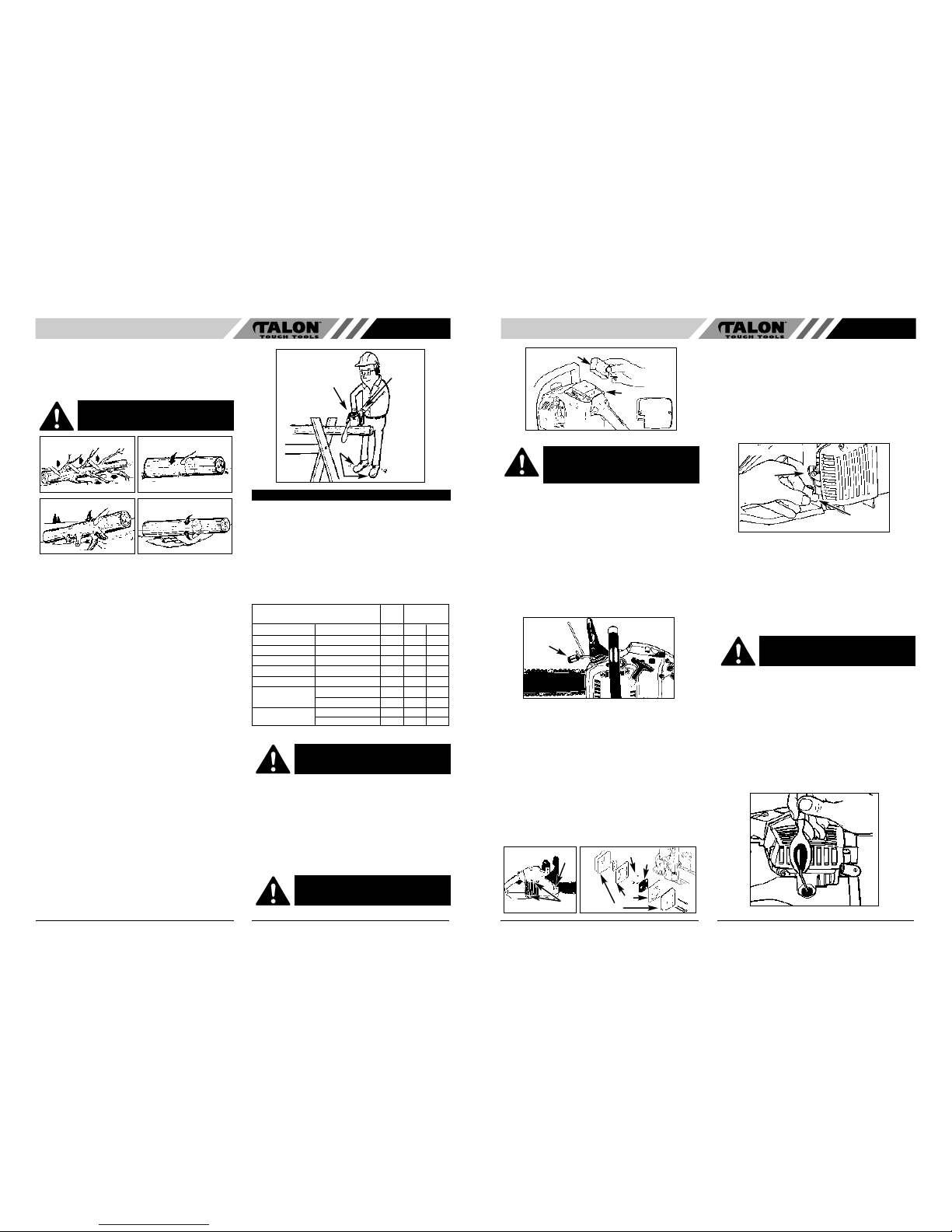
• LIMBING
Limbing a tree is the process of removing the branches
from a fallen tree. Do not remove supporting limbs (A)
until after the log is bucked (cut) into lengths (Fig. 15).
Branches under tension should be cut from the bottom
up to avoid binding the chain saw.
• BUCKING
Bucking is cutting a fallen log into lengths. Make sure
you have a good footing and stand uphill of the log when
cutting on sloping ground. If possible, the log should be
supported so that the end to be cut off is not resting on
the ground. If the log is supported at both ends and you
must cut in the middle, make a downward cut halfway
through the log and then make the undercut. This will
prevent the log from pinching the bar and chain. Be
careful that the chain does not cut into the ground when
bucking as this causes rapid dulling of the chain.
When bucking on a slope, always stand on the uphill
side.
1. Log supported along entire length: Cut from top
(overbuck), being careful to avoid cutting into the
ground (Fig. 16A).
2. Log supported on 1 end: First, cut from bottom
(underbuck) 1/3 diameter of log to avoid splintering.
Second, cut from above (overbuck) to meet first cut
and avoid pinching (Fig. 16B).
3. Log supported on both ends: First, overbuck 1/3
diameter of log to avoid splintering. Second,
underbuck to meet first cut and avoid pinching
(Fig. 16C).
NOTE: The best way to hold a log while bucking is to
use a sawhorse. When this is not possible, the log
should be raised and supported by the limb stumps or by
using supporting logs. Be sure the log being cut is
securely supported.
• BUCKING USING A SAWHORSE
For personal safety and ease of cutting, the correct
position for vertical bucking is essential (Fig. 17).
VERTICAL CUTTING:
A. Hold the saw firmly with both hands and keep the
saw to the right of your body while cutting.
B. Keep the left arm as straight as possible.
C. Keep weight on both feet.
All chain saw service, other than items listed here in
your user manual maintenance instructions, should be
performed by a professional.
• PREVENTIVE MAINTENANCE
A good preventive maintenance program of regular
inspection and care will increase life and improve
performance of your Talon chain saw. This maintenance
checklist is a guide for such a program.
Cleaning, adjustment, and parts replacement may be
required, under certain conditions, at more frequent
intervals than those indicated.
• AIR FILTER
TO CLEAN AIR FILTER:
1. Remove the top cover (A) by loosening the cover
retaining screws. Cover will lift off.
2. Lift the air filter (B) out of air-box (C) (Fig. 18).
3. Clean air filter. Wash filter in clean, warm, soapy
water. Rinse in clear, cool water. Air dry completely.
NOTE: It is advisable to have a supply of spare filters.
4. Install air filter. Install engine / air filter cover. Make
sure cover fits properly. Tighten the cover retaining
screws securely.
WARNING:
Never cut tree limbs while
standing on tree trunk.
Fig. 16A
Fig. 15
Fig. 16C
Fig. 16B
Fig. 17
B
A
C
MAINTENANCE INSTRUCTIONS
Maintenance EACH HOURS OF
CHECKLIST USE OPERATION
ITEM ACTION
Screws/Nuts/Bolts Inspect/Tighten
Air Filter Clean or Replace
Fuel Filter/Oil Filter Replace
Spark Plug Clean/Adjust/Replace
Spark Arrester Screen Inspect
Fuel Hoses Inspect
X
10 20
X
X
X
X
X
X
X
Replace as Required
Chain brake Inspect
Replace as Required
CAUTION: Never operate saw without the air
filter. Dust and dirt will be drawn into engine and
damage it. Keep the air filter clean!
WARNING:
Never perform maintenance
when the engine is hot, to avoid any
chance of burning hands or fingers.
• FUEL FILTER
1. Remove the fuel tank cap.
2. Bend a piece of soft wire.
3. Reach into fuel tank opening and hook fuel line.
Carefully pull the fuel line toward the opening until
you can reach it with your fingers.
NOTE: Do not pull hose completely out of tank.
4. Lift filter (A) out of tank (Fig. 19).
5. Pull filter off with a twisting motion. Discard filter.
6. Install new filter. Insert end of filter into tank
opening. Make sure filter sits in bottom corner of
tank. Use a long handle screwdriver to aid in filter
placement if necessary.
7. Fill tank with fresh fuel / oil mixture. See Section
FUEL AND LUBRICATION. Install fuel cap.
• SPARK ARRESTER SCREEN (Fig. 20A)
NOTE: A clogged spark arrester screen will dramatically
reduce engine performance.
1. Remove the 2 bar retaining nuts (A) and loosen the
2 screws (B) that secure the chain brake cover
(Fig. 20A).
2. Remove the chain brake cover. Remove the 3
screws that hold the muffler to the cylinder. The
muffler will lift off after retaining screws are removed
(Figure 7-4B).
3. Separate muffler halves (C). Remove the metal
baffles (D) and spacer tubes (E).
4. Discard the used spark arrester screen and replace
it with a new one (F) (Fig. 20B).
5. Reassemble the muffler components and install the
muffler to the cylinder. Tighten screws securely.
• SPARK PLUG
NOTE: For efficient operation of saw engine, spark plug
must be kept clean and properly gapped.
1. Push STOP switch down.
2. Disconnect the wire connector (A) from the spark
plug (B) by pulling and twisting at the same time
(Fig. 21).
3. Remove spark plug with spark plug socket wrench.
DO NOT USE ANY OTHER TOOL.
4. Reinstall a new spark plug, gapped at .635mm.
• CARBURETOR ADJUSTMENT
The carburetor was pre-set at the factory for optimum
performance. If further adjustments are necessary,
please take your unit to the nearest professional.
• STORING A CHAIN SAW
Storing a chain saw for longer than 30 days requires
storage maintenance. Unless the storage instructions
are followed, fuel remaining in the carburetor will evaporate, leaving gum-like deposits. This could lead to difficult starting and result in costly repairs.
1. Remove the fuel tank cap slowly to release any
pressure in tank. Carefully drain the fuel tank.
2. Start the engine and let it run until the unit stops to
remove fuel from carburetor.
3. Allow the engine to cool (approx. 5 minutes).
4. Using a spark plug wrench, remove the spark plug.
5. Pour 1 teaspoon of clean 2-cycle oil into the
combustion chamber. Pull starter rope slowly
several times to coat internal components. Replace
spark plug (Fig. 22).
NOTE: Store the unit in a dry place and away from
possible sources of ignition such as a furnace, gas hot
water heater, gas dryer, etc.
Fig. 18
B
C
A
CAUTION: Never operate your saw without
a fuel filter. The fuel filter should be
replaced after each 20 hours of use. Drain
fuel tank completely before changing filter.
Fig. 19
A
Fig. 21A
A
B
Fig. 20B
E
E
D
F
Fig. 21
A
B
CAUTION: Never store a chain saw for
longer than 30 days without performing the
following procedures.
Fig. 22
Page 6
NOTE: The condition of the oil passages can be easily
checked. If the passages are clear, the chain will
automatically give off a spray of oil within seconds of
starting the saw. Your saw is equipped with an automatic
oiler system.
• CHAIN MAINTENANCE
CHAIN TENSION:
Check the chain tension frequently and adjust as often
as necessary to keep the chain snug on the bar, but
loose enough to be pulled around by hand.
BREAKING IN A NEW SAW CHAIN:
A new chain and bar will need chain readjustment after
as few as 5 cuts. This is normal during the break-in
period, and the interval between future adjustments will
begin to lengthen quickly.
CHAIN LUBRICATION:
Always make sure the automatic oiler system is working
properly. Keep the oil tank filled with Talon Chain, Bar
and Sprocket Oil.
Adequate lubrication of the bar and chain during cutting
operations is essential to minimize friction with the guide
bar.
Never starve the bar and chain of lubricating oil. Running
the saw dry or with too little oil will decrease cutting
efficiency, shorten saw chain life, cause rapid dulling of
chain, and lead to excessive wear of bar from
overheating. Too little oil is evidenced by smoke or bar
discoloration.
CHAIN SHARPENING:
Chain sharpening requires special tools to ensure that
cutters are sharpened at the correct angle and depth.
For the inexperienced chain saw user, we recommend
that the saw chain be professionally sharpened by the
nearest professional Service Center. If you feel
comfortable sharpening your own saw chain, special
tools are available from the professional Service Center.
10
GB
WARNING: Never have more than 3 links
removed from a loop of chain. This could cause
damage to the sprocket.
11
GB
• REMOVING A UNIT FROM STORAGE
1. Remove spark plug.
2. Pull starter rope briskly to clear excess oil from combustion chamber.
3. Clean and gap spark plug or install a new spark plug
with proper gap.
4. Prepare unit for operation.
5. Fill fuel tank with proper fuel / oil mixture. See FUEL
AND LUBRICATION Section.
Lubrication of the sprocket tip is recommended after 10
hours of use or once a week, which ever occurs first.
Always thoroughly clean guide bar sprocket tip before
lubrication.
TOOLS FOR LUBRICATION:
The Lube Gun (optional) is recommended for applying
grease to the guide bar sprocket tip. The Lube Gun is
equipped with a needle nose tip which is necessary for the
efficient application of grease to the sprocket tip.
TO LUBRICATE SPROCKET TIP:
1. Move the STOP switch down.
NOTE: It is not necessary to remove the saw chain to
lubricate the guide bar sprocket tip. Lubrication can be
done on the job.
2. Clean the guide bar sprocket tip.
3. Using the Lube Gun (optional), insert needle nose
into the lubrication hole and inject grease until it
appears at outside edge of sprocket tip (Fig .23).
4. Rotate saw chain by hand. Repeat lubrication procedure until the entire sprocket tip has been greased.
GUIDE BAR MAINTENANCE:
Most guide bar problems can be prevented merely by
keeping the chain saw well maintained.
Insufficient guide bar lubrication and operating the saw
with chain that is TOO TIGHT will contribute to rapid bar
wear.
To help minimize bar wear, the following guide bar maintenance procedures are recommended.
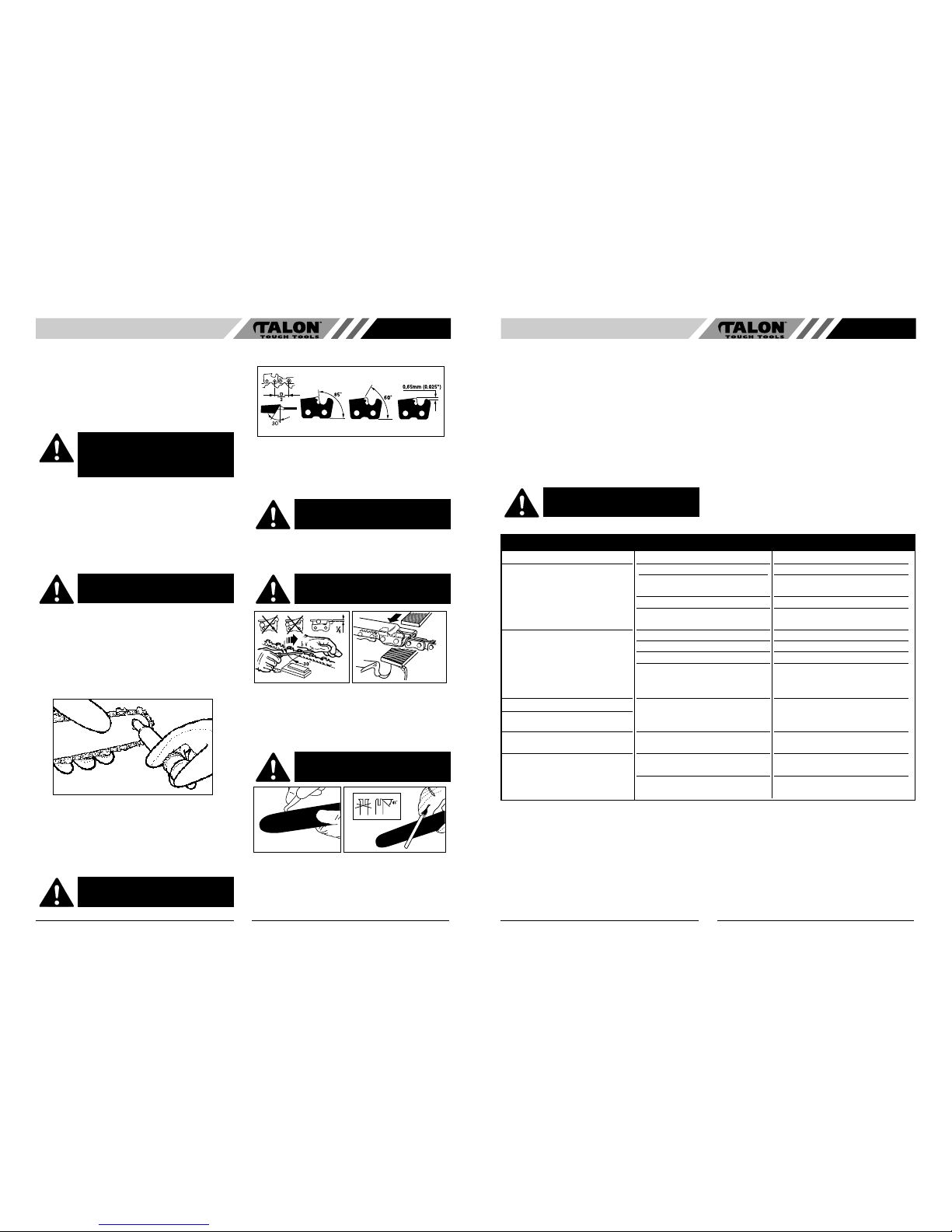
CHAIN SHARPENING - The pitch of the chain (Fig. 24) is
3/8” LoPro x .050”.
Sharpen the chain using protective gloves and a round file
of ø3/16” (4.8mm).
Always sharpen the cutters only with outward strokes
(Fig. 25) observing the values given in Fig. 24.
After sharpening, the cutting links must all have the same
width and length.
After every 3-4 times the cutters have been sharpened
you need to check the height of the depth gauges and, if
necessary, lower them using a flat file and template, then
round off the front corner. (Fig. 26)
GUIDE BAR - The bar should be reversed every 8 working hours to ensure uniform wear.
Keep the bar groove and lubrication hole clean using a
bar groove cleaner. (Fig. 27)
Check the bar rails frequently for wear and, if necessary,
remove the burs and square-up the rails using the flat file.
(Fig. 28)
BAR WEAR - Turn guide bar frequently at regular
intervals (for example, after 8 hours of use), to ensure
even wear on top and bottom of bar.
OIL PASSAGES - Oil passages on the bar should be
cleaned to ensure proper lubrication of the bar and chain
during operation.
CAUTION: The sprocket tip on your new saw has
been pre-lubricated at the factory. Failure to
lubricate the guide bar sprocket tip as explained
below will result in poor performance and seizure,
voiding the manufacturer’s warranty.
WARNING: Wear heavy duty work gloves
when handling the bar and chain.
Fig. 23
WARNING: Always wear protective gloves dur-
ing maintenance operations. Do not carry out
maintenance when the engine is hot.
Fig. 24
WARNING: A sharp chain produces well-
defined chips. When your chain starts to produce
sawdust, it is time to sharpen.
Fig. 26Fig. 25
WARNING: Proper adjustment of the depth
gauge is as important as proper sharpening of
the chain.
WARNING: Never mount a new chain on a
worn sprocket or self-aligning ring.
Fig. 28
Fig. 27
TRUBLESHOOTING THE ENGINE
PROBLEM
Unit won’t start or starts but will not run.
Unit starts, but engine has low power.
Engine hesitates.
No power under load.
Runs erratically.
Smokes excessively.
PROBABLE CAUSE
Incorrect starting procedures.
Incorrect carburetor mixture adjustment
setting.
Fouled spark plug
Fuel filter plugged.
Incorrect lever position on choke.
Dirty spark arrester screen.
Dirty air filter.
Incorrect carburetor mixture adjustment
setting.
Incorrect carburetor mixture adjustment
setting.
Incorrectly gapped spark plug.
Incorrect carburetor mixture adjustment
setting.
Incorrect fuel mixture.
CORRECTIVE ACTION
Follow instructions in the User Manual.
Have carburetor adjusted by an Authorized
Service Center.
Clean / gap or replace plug.
Replace fuel filter.
Move to RUN position.
Replace spark arrester screen.
Remove, clean and reinstall filter.
Have carburetor adjusted by an Authorized
Service Center.
Have carburetor adjusted by an Authorized
Service Center.
Clean / gap or replace plug.
Have carburetor adjusted by an Authorized
Service Center.
Use properly mixed fuel (25:1 mixture).
 Loading...