


OPERATING MANUAL
TALON RTS 2706
Talon® RTS Commercial Rackmount Recorders
200 MS/sec RF/IF Rackmount Recorder
Pentek, Inc.
One Park Way
Upper Saddle River, NJ 07458
(201) 818−5900
http://www.pentek.com/
Copyright © 2011−2015
Manual Part Number: 800.27060 Rev: 3.2 − March 16, 2014

Page ii Talon RTS 2706 Operating Manual
Manual Revision History
Date Rev Comments
5/2/11 −
1/17/12
1/17/12 1.0
1/23/12 1.1
3/19/12 1.2
5/8/12 1.3
5/22/12 1.4
6/25/12 2.0
12/12/12 2.1
5/1/13 2.2
5/14/13 2.3
6/3/13 2.4
6/4/13 2.5
8/4/14 3.0
9/3/14 3.1
3/16/15 3.2
Preliminary For information about revisions to the Preliminary version of this manual, contact Pentek.
Added Appendix C, Global Positioning System (Option 261) and Disk Drive Installation
appendix is now Appendix D. Chapter 1, Section 1.2, and Section 1.4: added description of
Option 270. Section 1.1, added GPS option. Revised Section 4.12.
Revised Section 4.9.1, Section 4.9.2, Section 4.12.3, and Table 4−8.
Added Section 4.11.1.2, Section 4.11.2.7, and Figure 4−22. Revised Figures 4−19, 4−20, and 4−
21. Revised Section 4.11.1 and Table 7−1.
Chapter 1, Section 1.2, and Section 1.4: added description of Option 271. Revised Figure 4−3,
Figure 4−4, Figure 4−17, Figure 4−12, Figure 4−19, Figure 4−23, Table 2−2, Table 4−2, Table
4−7, and Table 4−8. Replaced example profiles in Section 4.9. Changed Megabyte to
Megasample throughout Section 4.11 and Section 4.12.
Corrected the data type of the GPS fields in Table 7−1, Talon File Header Format.
Added Section 1.4.9, Section 2.1.4, Figure 2−4, and Section 4.11.2.9. Revised Figures 4−19, 4−
20, 4−21, 4−22, 4−26, 4−28, 4−30, 4−42, 4−43, 4−45, and 4−62. Revised Section 1.2, Section
4.14.3, Section 4.14.4, Section 4.14.12, Section 4.15.12, and Section A.1.
Revised Chapter 2 to reflect chassis variations. Revised Chapter 4 to reflect additional board
configuration screens.
Revised Warranty. Removed product options list from Chapter 1. See 2706 data sheet.
Revised Table 4−8.
Revised footnote for Table 4−2, Table 4−3, Table 4−5, and Table 4−7.
Revised Table 4−8.
Restructured the document.
Updated Chapter 9 for Revision 3.12 of the Signal Viewer. Added Section 5.8. Addressed KB
Cases 1431 and 1433.
Chapter 1, revised based on updated datasheet. Chapter 7, added data format information.
Warranty
Pentek warrants its Talon Recorder products to conform to published specifications and to be free from defects in materials and
workmanship for a period of one year from the date of delivery, when used under normal operating conditions and within the
service conditions for which they were furnished.
The obligation of Pentek arising from a warranty claim shall be limited to repairing or, optionally, replacing without charge any
product which proves to be defective within the term and scope of the warranty.
Pentek must be notified of the defect or nonconformity within the warranty period. The affected product must be returned with
shipping charges and insurance prepaid. Pentek will pay shipping charges for the return of product to buyer, except for products
returned from outside of the USA.
Limitations of Warranty
This warranty does not apply to products which have been repaired or altered by anyone other than Pentek or its authorized rep−
resentatives. This warranty does not extend to products that have been damaged by misuse, neglect, improper installation, unau−
thorized modification, or extreme environmental conditions, that fall outside of the scope of the product’s environmental
specifications.
Due to the normal, finite write−cycle limits of Solid State Drives (SSDs), Pentek shall not be liable for warranty coverage of SSDs
caused by wear−related issues that arise as an SSD reaches its write−cycle limit.
Pentek specifically disclaims merchantability or fitness for a particular purpose. Pentek shall not be held liable for incidental or
consequential damages arising from the sale, use, or installation of any Pentek product. Regardless of circumstances, Pentek's lia−
bility under this warranty shall not exceed the purchase price of the product.
Printed in the United States of America.

Page iii Talon RTS 2706 Operating Manual
Service and Repair
You must obtain a Return Material Authorization (RMA) before returning any product to Pentek for service or repair. RMA
requests must be submitted online at: Return Material Authorization Form
After the form is completed in its entirety and submitted, Pentek shall e−mail you a receipt and start processing your request.
Once your request has been approved, Pentek shall e−mail you an RMA number, shipping instructions, and a quotation, if the
product is out of warranty.
Carefully package the product in its original packaging if it is still available, and ship it to Pentek prepaid (if within the US) or free
domicile DDP (if outside the US). Pentek shall not be responsible for loss or damage in shipment to Pentek, so you are strongly
encouraged to insure the shipment for its full replacement value.
When the work is completed, we will return the product to you along with a statement of work performed.
Service phone: 201−818−5900 • fax: 201−818−5697 • email: info@pentek.com
Copyrights
The contents of this publication are Copyright © 2011−2015, Pentek, Inc. All Rights Reserved. Contents of this publication may not
be reproduced in any form without written permission.
Trademarks
Pentek, RTS, SystemFlow, and Talon are trademarks or registered trademarks of Pentek, Inc.
Intel and Core are trademarks or registered trademarks of Intel. Microsoft and Windows are registered trademarks of Microsoft
Corporation. PCI, PCI Express, PCIe, and PCI−SIG are trademarks or registered trademarks of PCI−SIG. Symmetricom is a regis−
tered trademark of Symmetricom, Inc. Xilinx and Virtex are registered trademarks or trademarks of Xilinx, Inc.

This page is intentionally blank

Talon RTS 2706 Operating Manual Page v
Page
Table of Contents
Chapter 1: Overview of the Pentek Talon RTS 2706
1.1 Features of the Pentek Talon RTS 2706..............................................................................................1
1.2 Basic Principles of Operation..............................................................................................................2
1.3 Hardware...............................................................................................................................................2
1.4 Software .................................................................................................................................................2
1.5 Talon RTS 2706 Specifications.............................................................................................................3
1.5.1 PC Workstation ...................................................................................................................3
1.5.2 Analog Signal Inputs ..........................................................................................................3
1.5.3 A/D Converters ..................................................................................................................3
1.5.4 Digital Downconverter ......................................................................................................3
1.5.5 Analog Signal Outputs ......................................................................................................4
1.5.6 Digital Upconverter and D/As .........................................................................................4
1.5.7 Sample and Reference Clocks ...........................................................................................4
1.5.8 Physical and Environmental .............................................................................................4
Chapter 2: Hardware Description
2.1 Front of Chassis.....................................................................................................................................5
Figure 2−1: Front of Chassis ..............................................................................................................5
2.1.1 CD/DVD R/W Optical Drive ...........................................................................................5
Figure 2−2: Close−up View of CD/DVD Drive and SATA Drives...........................6
2.1.2 Removable SATA RAID Drives ........................................................................................6
2.1.3 Controls and Indicators on the Front of the Chassis .....................................................7
Figure 2−3: Controls and Indicators on the Front of the Chassis..............................7
2.2 Back of Chassis......................................................................................................................................8
Figure 2−4: Back of Chassis ...............................................................................................................8
2.2.1 IEC Power Receptacles .......................................................................................................8
2.2.2 Pentek Board I/O, Optional GPS, and Video Connections ..........................................8
2.2.3 PC Motherboard I/O Panel ...............................................................................................8
Chapter 3: Pentek Board I/O Connections
Table 3−1: Recording/Playback Options.........................................................................................9
Table 3−2: Documentation for Pentek Cobalt PCIe Boards Used in a Talon System............9
Rev: 3.2

Page vi Talon RTS 2706 Operating Manual
Page
Table of Contents
Chapter 4: Starting the System
4.1 Unpacking the Unit............................................................................................................................11
4.2 Power Requirements.......................................................................................................................... 11
4.3 Preparing the System for Operation................................................................................................ 11
4.4 Boot−Up Sequence ............................................................................................................................. 12
4.5 Maintenance........................................................................................................................................ 12
4.6 Safety Precautions and Warnings ................................................................................................... 13
Chapter 5: Configuring the Talon System
5.1 Introduction: SystemFlow Software................................................................................................ 15
5.2 Launching the SystemFlow GUI...................................................................................................... 15
5.3 Description of the SystemFlow GUI................................................................................................16
Figure 5−1: Talon Main Configuration Screen............................................................................ 16
5.4 Configure Screen: Talon System Block Diagram........................................................................... 17
Figure 5−2: Configure Screen − Talon System Sample Block Diagram................................. 17
5.5 Configuring a Remote Server ........................................................................................................... 18
Figure 5−3: Configure Screen − Remote Server Configuration ...............................................18
5.6 Configuring the Talon System Using a Profile ..............................................................................18
Figure 5−4: Configure Screen − Profile Configuration Buttons............................................... 19
5.6.1 Loading a profile ..............................................................................................................19
5.6.2 Saving a Profile .................................................................................................................19
5.7 Configuring the Talon System Using the Configuration Panel...................................................20
5.7.1 Configuration Panel ......................................................................................................... 20
Figure 5−5: Configuration Panel ...................................................................................20
5.7.2 Input Channel Clock Parameters ...................................................................................21
Figure 5−6: Input Channel Clock Parameters Configuration Screen..................... 21
Table 5−1: Input Channel Clock Parameters ..............................................................22
5.7.3 Configuring Input Channel Parameters .......................................................................23
Figure 5−7: Example of Input Channel Parameters Configuration Screen........... 23
Table 5−2: Input Channel Parameters.......................................................................... 24
5.7.4 Output Channel Clock Parameters ................................................................................25
Figure 5−8: Output Channel Clock Parameters Configuration Screen..................25
Table 5−3: Output Channel Clock Parameters........................................................... 26
5.7.5 Configuring Output Channel Parameters ....................................................................27
Figure 5−9: Output Channel Parameters Configuration Screen ............................. 27
Table 5−4: Output Channel Parameters.......................................................................28
5.8 Sync Guidelines .................................................................................................................................. 29
Rev: 3.2

Talon RTS 2706 Operating Manual Page vii
Page
Table of Contents
Chapter 6: Recording a Signal
6.1 The Record Screen ..............................................................................................................................31
Figure 6−1: Record Screen................................................................................................................31
6.2 Record Channel Controls ..................................................................................................................32
Figure 6−2: Record Screen: Channel Controls..............................................................................32
6.2.1 File Name and Browse .....................................................................................................32
6.2.2 Overwrite ...........................................................................................................................33
6.2.3 Record Until Manual Stop ...............................................................................................33
6.2.4 Record by Time .................................................................................................................33
6.2.5 Record by File Size ...........................................................................................................33
6.2.6 Loop ....................................................................................................................................34
6.2.7 Master Record ...................................................................................................................35
6.2.8 Record Button ....................................................................................................................35
6.2.9 Stop Button ........................................................................................................................35
6.2.10 Status ..................................................................................................................................35
6.2.11 Channel Position (MSs) ....................................................................................................35
6.2.12 Data Rate (MS/s) ..............................................................................................................35
6.2.13 Data Loss ............................................................................................................................36
6.3 Master Record Controls .....................................................................................................................37
Figure 6−3: Record Screen − Master Controls..............................................................................37
6.3.1 Master Record Button ......................................................................................................37
6.3.2 Master Stop Button ...........................................................................................................37
6.3.3 Record Until Stop − Master Recording ..........................................................................37
6.3.4 Record by Time − Master Recording .............................................................................38
6.3.5 Master Status .....................................................................................................................38
6.3.6 Master Data Loss ..............................................................................................................38
6.3.7 Master Current Position (Secs) .......................................................................................39
6.3.8 Record GPS Position .........................................................................................................39
6.3.9 Signal Viewer ....................................................................................................................39
6.3.10 Programmable Recording Start Time ............................................................................39
Figure 6−4: Start Time......................................................................................................39
Chapter 7: Recorded Data Format
7.1 IF data...................................................................................................................................................41
7.2 Baseband data .....................................................................................................................................41
7.3 File Header Format.............................................................................................................................42
Table 7−1: Talon File Header Format.............................................................................................42
Rev: 3.2

Page viii Talon RTS 2706 Operating Manual
Page
Table of Contents
Chapter 8: Playing a Recorded File
8.1 The Play Screen................................................................................................................................... 45
Figure 8−1: Play Screen .................................................................................................................... 45
8.2 Play Channel Controls.......................................................................................................................46
Figure 8−2: Play Screen: Channel Controls..................................................................................46
8.2.1 File Name and Browse ..................................................................................................... 46
8.2.2 Start Position .....................................................................................................................46
8.2.3 Play Until Manual Stop ...................................................................................................46
8.2.4 Play by Time .....................................................................................................................47
8.2.5 Play by File Size ................................................................................................................ 47
8.2.6 Loop ...................................................................................................................................47
8.2.7 Master Play ........................................................................................................................ 48
8.2.8 Play Button ........................................................................................................................48
8.2.9 Stop Button ........................................................................................................................ 48
8.2.10 Status ..................................................................................................................................48
8.2.11 Channel Position (MSs) ...................................................................................................48
8.2.12 Data Rate (MS/s) ..............................................................................................................48
8.2.13 Data Loss ...........................................................................................................................49
8.3 Master Play Controls ......................................................................................................................... 50
Figure 8−3: Play Screen − Master Controls .................................................................................. 50
8.3.1 Master Play Button ...........................................................................................................50
8.3.2 Master Stop Button ..........................................................................................................50
8.3.3 Play Until Manual Stop − Master Playback ................................................................. 50
8.3.4 Play by Time − Master Playback .................................................................................... 51
8.3.5 Master Status ..................................................................................................................... 51
8.3.6 Master Data Loss .............................................................................................................. 51
8.3.7 Master Current Position (Secs) .......................................................................................51
8.3.8 File Viewer ........................................................................................................................51
Chapter 9: Monitoring Input Signals with Signal Viewer
9.1 Introduction: the Signal Viewer ....................................................................................................... 53
9.2 Signal Viewer Displays and Display Controls...............................................................................54
Figure 9−1: Signal Viewer (Default Display) .............................................................................. 54
Figure 9−2: Samples/Time Switch..................................................................................................54
Figure 9−3: Amplitude Switch (Time Display) ........................................................................... 55
Figure 9−4: Display Type Switch ...................................................................................................55
Figure 9−5: Signal Viewer with Frequency−Time−Intensity Display in Left Window...... 56
Figure 9−6: Amplitude Switch (Frequency Magnitude Display) ............................................56
Rev: 3.2

Talon RTS 2706 Operating Manual Page ix
Page
Table of Contents
Chapter 9: Monitoring Input Signals with Signal Viewer (continued)
9.3 Input Controls .....................................................................................................................................57
9.3.1 Resume, Pause and Close ................................................................................................57
Figure 9−7: Resume, Pause and Close Buttons ...........................................................57
9.3.2 Channel Index and Board Index .....................................................................................57
Figure 9−8: Channel Index and Board Index...............................................................57
9.3.3 FFT Size ..............................................................................................................................57
Figure 9−9: FFT Size .........................................................................................................57
9.3.4 Spectrum Averaging ........................................................................................................58
Figure 9−10: Averaging Control.....................................................................................58
9.3.5 Baseband / IF Frequency Scale .......................................................................................58
Figure 9−11: Baseband / IF Frequency Scale Control.................................................58
9.4 Data Displayed....................................................................................................................................59
9.4.1 System, Server and Board Model ...................................................................................59
Figure 9−12: Example of System, Server, and Board Model Fields ........................59
9.4.2 Signal Characteristics .......................................................................................................59
Figure 9−13: Signal Characteristics ...............................................................................59
9.4.3 Amplitude Calculator ......................................................................................................60
Figure 9−14: Amplitude Calculator...............................................................................60
9.4.4 Distortion Calculator ........................................................................................................61
Figure 9−15: Distortion Calculator ................................................................................61
9.4.5 Resolution Bandwidth Calculator ..................................................................................61
Figure 9−16: Resolution Bandwidth Calculator..........................................................61
Chapter 10: Analyzing Recorded Signals with File Viewer
10.1 Introduction: the File Viewer............................................................................................................63
10.2 Differences Between the Signal Viewer and the File Viewer.......................................................63
10.3 Selecting a File to View ......................................................................................................................64
Figure 10−1: Playback Controls.......................................................................................................64
Figure 10−2: File Viewer File Selection Browser.........................................................................65
10.4 Display and Playback Controls ........................................................................................................66
Figure 10−3: Example of File Viewer .............................................................................................66
10.4.1 Display Controls ...............................................................................................................66
10.4.2 Playback Controls .............................................................................................................66
Figure 10−4: Play, Pause and Quit buttons..................................................................67
10.4.3 Playback Speed .................................................................................................................67
Figure 10−5: Playback Speed Switch ............................................................................67
10.4.4 Spectrum Averaging ........................................................................................................68
Figure 10−6: Exponential Averaging Control..............................................................68
Rev: 3.2

Page x Talon RTS 2706 Operating Manual
Page
Table of Contents
Chapter 10: Analyzing Recorded Signals with File Viewer (continued)
10.5 Data Displayed ...................................................................................................................................69
10.5.1 Board, System, Time Stamp, and Optional GPS ..........................................................69
Figure 10−7: Board, System, Time Stamp, and Optional GPS ................................ 69
10.5.2 Signal Characteristics .......................................................................................................69
Figure 10−8: Signal Characteristics............................................................................... 69
10.5.3 Distortion Calculator .......................................................................................................70
Figure 10−9: Distortion Calculator................................................................................70
10.5.4 Amplitude Calculator ...................................................................................................... 71
Figure 10−10: Amplitude Calculator............................................................................. 71
10.6 Data Extraction Utility....................................................................................................................... 72
Figure 10−11: Playback Controls .................................................................................................... 72
Figure 10−12: Data Extraction Utility ............................................................................................72
Chapter 11: Display Controls for Signal and File Viewer
11.1 Display Zooming................................................................................................................................ 73
Figure 11−1: Time and FFT (Frequency) Display Controls....................................................... 73
Figure 11−2: Time and FFT (Frequency) Display Controls....................................................... 73
11.1.1 Horizontal Zoom .............................................................................................................. 74
11.1.2 Vertical Zoom ...................................................................................................................74
11.1.3 Windowed Zoom ............................................................................................................. 74
11.1.4 Full Screen .........................................................................................................................74
11.1.5 Point Zoom ........................................................................................................................ 74
11.1.6 Point Shrink ....................................................................................................................... 74
11.2 Display Panning ................................................................................................................................. 75
11.3 Reset Scale − Time and Frequency Displays.................................................................................. 75
Figure 11−3: Reset Scale Buttons − Time and Frequency Displays......................................... 75
11.4 Cursor Operation ............................................................................................................................... 76
Figure 11−4: Create Cursor Menu .................................................................................................. 76
Figure 11−5: New Free Cursor 0...................................................................................................... 76
Figure 11−6: Cursor 0 Properties .................................................................................................... 77
Figure 11−7: Cursor 0 Attributes .................................................................................................... 78
Figure 11−8: Cursor Window with Single Free Cursor and Single−Plot Cursor.................. 78
Rev: 3.2

Talon RTS 2706 Operating Manual Page xi
Page
Table of Contents
Appendix A: Rugged Transit Case (Option 262)
A.1 Introduction...........................................................................................................................................1
A.2 Description.............................................................................................................................................1
Figure A−1: Rugged Transit Case with Casters and Doors Closed ...........................................2
Figure A−2: Empty Rugged Transit Case with Casters and Both Doors Open .......................3
Figure A−3: Rugged Transit Case with Talon RTS 2706 and Keyboard/Monitor Installed .4
Appendix B: Rackmount Keyboard / Monitor (Option 263)
B.1 Introduction...........................................................................................................................................1
B.2 Opening the Keyboard/Monitor........................................................................................................1
Figure B−1: Rackmount Keyboard / Monitor in Rugged Transit Case (Options 263 & 262) 1
Appendix C: Global Positioning System (Option 261)
Figure C−1: Example of GPS (Option 261) in Pentek Talon RTS 2706 System.......................1
Appendix D: Disk Drive Installation
D.1 Introduction...........................................................................................................................................1
D.2 Description.............................................................................................................................................1
Figure D−1: Drive Bays and Corresponding LEDs.......................................................................1
Figure D−2: Disk Drive Identification Label.................................................................................2
Rev: 3.2

Page xii Talon RTS 2706 Operating Manual
Page
This page is intentionally blank
Table of Contents
Rev: 3.2

Talon RTS 2706 Operating Manual Page 1
Chapter 1: Overview of the Pentek Talon RTS 2706
This chapter provides an overview of this operating manual and an overview of the
Talon RTS 2706 recording system. The following information is provided:
• Section 1.1 lists the features of the Talon recording system.
• Section 1.2 describes how the Talon system operates.
• Section 1.3 describes the Talon system’s hardware.
• Section 1.4 describes the Talon system’s software.
• Section 1.5 provides the Talon system’s specifications.
1.1 Features of the Pentek Talon RTS 2706
Pentek's Talon RTS 2706 recording system offers the following features:
• Complete multiband recording and playback system
•4U 19−inch industrial rackmount PC server chassis
®
•Windows
• 200 MHz max. 16−bit A/D sampling for recording − up to eight channels
• 1.25 GHz max. 16−bit D/A sampling for playback − up to eight channels
• 80 MHz max. record and playback signal bandwidths
• Can record and play back IF frequencies up to 700 MHz
•Real−time aggregate recording rates of up to 1.6 GB/sec
• Removable solid state drives (SSDs)
• Up to 100 TB of storage to NTFS RAID disk array
• RAID levels of 0, 1, 5, 6, 10, and 50
• SystemFlow
•C−callable API for integration of recorder into application
7 Professional workstation with Intel® Core™ i7 processor
®
GUI with signal viewer analysis tool
• File headers include time stamping and recording parameters
• DDC decimation and DUC interpolation range from 2 to 65,536
• Optional GPS for time and position stamping
Rev.: 3.2

Page 2 Talon RTS 2706 Operating Manual
1.2 Basic Principles of Operation
The Talon® RTS 2706 is a multiband recording and playback system for recording and
reproducing high−bandwidth signals. The RTS 2706 uses 16−bit, 200 MHz A/D con−
verters and provides sustained recording rates up to 1.6 GB/sec in a four−channel con−
figuration.
®
The RTS 2706 uses Pentek’s high−powered Virtex−6−based Cobalt
provide flexibility in channel count, with optional digital downconversion capabilities.
Optional 16−bit, 1.25 GHz D/A converters with digital upconversion allow real−time
reproduction of recorded signals.
A/D sampling rates, DDC decimations and bandwidths, D/A sampling rates, and
DUC interpolations are among the GUI−selectable system parameters, providing a
fully−programmable system capable of recording and reproducing a wide range of
signals. Optional GPS time and position stamping allows the user to record this critical
signal information
modules, which
1.3 Hardware
The RTS 2706 is configured in a 4U 19−inch rack−mountable chassis, with hot−swap−
pable data drives, front panel USB ports, and I/O connectors on the rear panel. Systems
are scalable to accommodate multiple chassis to increase channel counts and aggregate
data rates. All recorder chassis are connected via Ethernet and can be controlled from a
single GUI either locally or from a remote PC.
Multiple RAID levels, including 0, 1, 5, 6, 10, and 50, provide a choice for the required
level of redundancy. The hot−swappable HDDs provide storage capacities of up to 100
TB in a single 6U chassis.
1.4 Software
The RTS 2706 includes the SystemFlow Recording Software. SystemFlow features a
Windows−based GUI (Graphical User Interface) that provides a simple means to con−
figure and control the system. Custom configurations can be stored as profiles and later
loaded when needed, allowing you to select preconfigured settings with a single click.
SystemFlow also includes signal viewing and analysis tools, that allow the user to
monitor the signal prior to, during, and after a recording session. These tools include a
virtual oscilloscope and a virtual spectrum analyzer.
Built on a Windows 7 Professional workstation, the RTS 2706 allows the user to install
post processing and analysis tools to operate on the recorded data. The RTS 2706
records data to the native NTFS file system, providing immediate access to the
recorded data.
Rev.: 3.2
Data can be off−loaded via two gigabit Ethernet ports, six USB 2.0 ports, or two eSATA
ports. Additionally, data can be copied to optical disk, using the 8X double layer
DVD±R/RW drive.

Talon RTS 2706 Operating Manual Page 3
1.5 Talon RTS 2706 Specifications
1.5.1 PC Workstation
• Operating System: Microsoft® Windows® 7 Professional
®
• Recording Software: Pentek
®
• Processor: Intel
Core™ i7 processor
• Clock Speed: 2.0 GHz or greater
•SDRAM: 6 GB
•RAID:
• Storage: 2 to 100 TB
• Supported Levels: 0, 1, 5, 6, 10, and 50
1.5.2 Analog Signal Inputs
SystemFlow® software
• Input Type: Transformer−coupled, front panel female SSMC connectors
• Transformer Type: Coil Craft WBC4−6TLB
• Full Scale Input: +8 dBm into 50 ohms
• 3 dB Passband: 300 kHz to 700 MHz
1.5.3 A/D Converters
• Type: Texas Instruments ADS5485
• Sampling Rate (ƒ
): 10 MHz to 200 MHz
s
•Resolution: 16 bits
• A/D Record Bandwidth: ƒ
•Anti−Aliasing Filters: External, user−supplied
1.5.4 Digital Downconverter
• Type: Virtex−6 FPGA, Pentek DDC IP Core
/2 = Nyquist bandwidth
s
• Decimation Range (D): 2 to 65,536
• IF Center Frequency Tuning: DC to ƒ
• DDC Usable Bandwidth: 0.4*ƒ
/D (80 MHz max)
s
, 32 bits
s
Rev.: 3.2

Page 4 Talon RTS 2706 Operating Manual
1.5 Talon RTS 2706 Specifications (continued)
1.5.5 Analog Signal Outputs
• Output Type: Transformer−coupled, front panel female
• SSMC connectors
• Full Scale Output: +4 dBm into 50 ohms
• 3 dB Passband: 300 kHz to 700 MHz
1.5.6 Digital Upconverter and D/As
• Type: TI DAC5688 and Pentek−installed interpolation IP core
• Interpolation: 2 to 65,536
• Input Data Rate: 250 MHz max.
• Output IF: DC to 400 MHz
• Output Signal: Analog, real or quadrature
• Output Sampling Rate: 800 MHz max. with 2, 4 or 8 interpolation
•Resolution: 16 bits
1.5.7 Sample and Reference Clocks
• Clock Sources: Selectable from onboard programmable VCXO, external
or LVDS clocks
• External Clock Type: Front panel female SSMC connector, sine wave,
0 to +10 dBm, AC−coupled, 50 ohms, 10 to 200 MHz
•Multi−Recorder Sync/Gate Bus: 26−pin connector, dual clock/sync/
gate input/output LVDS buses; one sync/gate input TTL signal
1.5.8 Physical and Environmental
• Size: 19" W x 26" D x 7" H
Rev.: 3.2
• Weight: 60−85 lb
• Operating Temp: +5° to +45° C
• Storage Temp: –40° to +85° C
• Relative Humidity: 5 to 95%, non−condensing
• Power Requirements: 100 to 240 VAC, 50 to 60 Hz, 500 W max.

Talon RTS 2706 Operating Manual Page 5
Chapter 2: Hardware Description
2.1 Front of Chassis
Figure 2−1 below shows the front view of a Talon RTS 2706 with 16 SATA RAID drives.
Your Talon system may have more or fewer SATA RAID drives depending on the stor−
age options you have chosen, so your unit may look somewhat different. Some units
also have lockable doors on the front of the chassis.
Figure 2−1: Front of Chassis
2.1.1 CD/DVD R/W Optical Drive
The CD/DVD R/W drive (Figure 2−2) can read and write both CDs and
DVDs. For a close−up view of the CD/DVD drive. The tray is ejected and
injected by pushing the Eject button while the Talon system is powered on.
When the Active LED is on, the CD/DVD drive heads are being positioned,
or the drive is reading from or writing to a CD/DVD.
NOTE:
To avoid data errors, do not eject a CD/DVD when the Active LED
is on.
Rev.: 3.2

Page 6 Talon RTS 2706 Operating Manual
2.1 Front of Chassis (continued)
Rev.: 3.2
Figure 2−2: Close−up View of CD/DVD Drive and SATA Drives
2.1.2 Removable SATA RAID Drives
The quantity and arrangement of SATA drives varies, depending on the
storage options selected. In a close−up view of the drives, Figure 2−2 shows
the SATA drive removal tab and status LEDs. The upper SATA drive LED is
the power indicator and the lower LED is the drive activity indicator.

Talon RTS 2706 Operating Manual Page 7
A. HDD tray ac ti vi ty LE Ds
B. USB 2.0 ports
C. System reset button
D. Alarm mute button
E. System HDD activity LED
F. Power LED
G. Fan failure/overheat LED
H. LAN 1 and LAN 2 LEDs
I. Power butt on
A
BCDEFGH
I
Figure 2−3: Controls and Indicators on the Front of the Chassis
2.1 Front of Chassis (continued)
2.1.3 Controls and Indicators on the Front of the Chassis
Figure 2−3 shows a close−up view of the indicators, controls, and USB ports
located on the front of a Talon RTS 2706 chassis.
• The following LED indicators are on the front of the chassis: HDD tray
activity, system HDD activity, power indicator, fan failure/overheat
indicator, and LAN activity.
• The controls include a system reset button, an alarm mute button, and a
power button.
• To the right of the HDD tray activity LEDs are two USB 2.0 ports.
Rev.: 3.2

Page 8 Talon RTS 2706 Operating Manual
2.2 Back of Chassis
Figure 2−4 shows the rear view of a Talon RTS system.
Figure 2−4: Back of Chassis
2.2.1 IEC Power Receptacles
A grounded 3−prong IEC power receptacle located on the rear of the Talon
RTS chassis accepts a modular power cord appropriate for various power
outlets around the world. To prevent a shock hazard, be sure the power cord
and the outlet provide a connection to ground.
2.2.2 Pentek Board I/O, Optional GPS, and Video Connections
The Pentek board I/O, optional GPS, and video connections are located on
the right side of the rear of the Talon RTS system. The number and model of
the Pentek boards will vary depending on the options you selected, so the
appearance of this section of the rear of the Talon RTS system will vary.
2.2.3 PC Motherboard I/O Panel
The Talon system’s PC motherboard I/O panel includes connections for a
keyboard and mouse, as well as USB and Ethernet ports. The connections for
the integrated audio system of the motherboard (speakers, mic, etc.) are not
used for the Talon system’s recording or playback functions.
Rev.: 3.2

Talon RTS 2706 Operating Manual Page 9
Chapter 3: Pentek Board I/O Connections
This chapter describes the Pentek Cobalt PCIe board(s) in your Talon RTS 2706 system.
The number of boards and models used vary depending on the options you selected for
your Talon system, as shown in Table 3−1. The video port is also located in this section
of the rear panel.
Table 3−1: Recording/Playback Options
Pentek Cobalt PCIe
Board Model
78620 1 0
78620 1 1
78620 2 0
78620 2 1
78660 and 78670 2 2
78620 3 0
78660 4 0
78660 and 78670 4 4
two 78660 boards 8 0
two 78660 boards plus
two 78670 boards
Record
Channels
88
Play
Channels
The Pentek Cobalt PCIe board I/O connections and LEDs are described in Chapter 2 of
the corresponding installation manual(s) for the board(s) in your Talon system. You
can view these manuals online at http://www.pentek.com/support/Documenta−
tion.cfm. Table 3−2 lists the title and part number of the installation manual used for each
board.
Table 3−2: Documentation for Pentek Cobalt PCIe Boards Used in a Talon System
Pentek
PCIe Board
Model
78620 Installation Manual − Model 78620 3−Ch A/D 2−Ch D/A PCIe Board 800.78620
78621
78660
78661
78670 Installation Manual − Model 78670 4−Ch 1GHz D/A 800.78670
Installation Guide − Model 78621 3−Ch A/D 2−Ch D/A, Multiband
DDC Core & Interpolation PCIe Board
Installation Manual − Model 78660 4−Channel 200 MHz A/D Cobalt
Family PCIe Board
Installation Manual − Model 78661 4−Channel 200 MHz A/D,
Multiband DDC Core Cobalt Family PCIe Board
Installation Manual Title
Document
Number
800.78621
800.78660
800.78661
Part
Rev.: 3.2

Page 10 Talon RTS 2706 Operating Manual
This page is intentionally blank
Rev.: 3.2

Talon RTS 2706 Operating Manual Page 11
Chapter 4: Starting the System
This chapter describes how to set up and start your Talon system:
• Section 4.1 covers unpacking the unit.
• Section 4.2 provides power requirements.
• Section 4.3 describes how to prepare the system for operation.
• Section 4.4 describes the Talon system’s boot−up sequence.
• Section 4.5 provides information about maintenance.
• Section 4.6 provides safety precautions.
4.1 Unpacking the Unit
Your Talon recording system was shipped in a specially designed shipping box. Upon
receipt, inspect the outside of the box for any damage in shipping. If damage is evident
and the unit shows physical damage as well, report the damage to the shipping carrier.
4.2 Power Requirements
The Talon system is powered from an AC source providing 100 to 240 VAC at 50 or 60
Hz. Line power is connected through an IEC receptacle located at the rear of the unit.
The standard line cord supplied has a 3−conductor grounded plug for North America.
For other locations, use the appropriate grounded line cord compliant with your local
standards and outlet types.
4.3 Preparing the System for Operation
Follow the steps below to prepare the system for operation.
1) Make sure the Talon system and all equipment to be attached is powered off.
2) If connecting to a network, attach an Ethernet cable.
3) Attach a keyboard, mouse, and monitor.
4) Attach signal I/O cables from external equipment to the Talon recording system.
5) Attach the Talon recording system power cord to the power source.
6) Turn on Talon recording system power by pressing the power switch.
7) Apply power to the connected equipment.
Rev.: 3.2

Page 12 Talon RTS 2706 Operating Manual
4.4 Boot−Up Sequence
The following sequence of events will occur during a normal boot−up sequence.
1) Windows 7 will boot completely.
2) Windows Desktop should appear.
3) The Talon system Server will launch automatically in a DOS window.
4) To launch the Talon recording system GUI client, double−click on the Talon "client"
icon.
NOTE:
NOTE:
4.5 Maintenance
When working on or cleaning the Talon recording system, always use a clean, flat
working surface area. Although the unit requires little maintenance, all the components
must be handled with care and according to its specifications.
The GUI takes a few seconds to launch initially. Please wait.
Do not disable the Windows networking interface. The Talon
system’s software uses the Windows networking interface as part
of the node−locking mechanism. If the Windows networking
interface is disabled, the server software will not pass the node−
lock check.
Rev.: 3.2

Talon RTS 2706 Operating Manual Page 13
WARNING:
4.6 Safety Precautions and Warnings
Electrical current from power, telephone, and communication cables
is hazardous
To avoid a shock hazard, connect and disconnect cables following
the instructions in Section 4.3 when installing, servicing, moving, or
opening the covers of your Talon recording system or attached
devices.
If you keep the power on while adding or removing components or
cables, damage might be caused to the unit or its components. You
might even put yourself in danger of injury.
Only qualified service personnel should service your Talon system.
.
Always handle cables by holding the connector, not the cord
Do not force a connector when trying to plug it into a socket.
If for any reasons the AC power cable becomes damaged or broken,
disconnect the cable immediately and replace it with a new one.
It is important to plug the AC power cord into a grounded three−
prong outlet for security reasons.
Never try to disassemble the grounding plug, as it is a safety feature.
Use only a grounded outlet to keep your computer and yourself safe.
.
Rev.: 3.2

Page 14 Talon RTS 2706 Operating Manual
This page is intentionally blank
Rev.: 3.2

Talon RTS 2706 Operating Manual Page 15
Chapter 5: Configuring the Talon System
This chapter describes how to configure the Talon system using SystemFlow® software:
• Section 5.1 describes the SystemFlow software.
• Section 5.2 describes how to launch the SystemFlow GUI.
• Sections 5.3 and 5.4 describe the SystemFlow GUI and configuration screens.
• Section 5.5 describes how to configure a remote server.
• Section 5.6 describes how to configure the Talon system using a profile.
• Section 5.7 describes how to configure the Talon system using configuration screens.
• Section 5.8 provides some synchronization guidelines.
5.1 Introduction: SystemFlow Software
The Talon system’s SystemFlow software consists of a client application that provides a
user interface and a server application that controls the instrument. The client applica−
tion consists of a GUI (Graphical User Interface) running on a Microsoft Windows
platform. Communication between the server and client application take place using
the standard sockets protocol.
The GUI client is controlled by the SystemFlow operator and communicates with the
Talon system server, sending specific commands and system parameters to the Talon
system server to set up the system and to instruct it to perform specific actions.
SystemFlow includes a complete API (Application Programming Interface) supporting
control and status queries of all operations of the Talon system from a custom applica−
tion. For information about using the SystemFlow API, refer to the SystemFlow API
User’s Development Guide (800.27xx2).
5.2 Launching the SystemFlow GUI
The Talon server is a Windows application and it is automatically launched when the
Talon system is started. The Talon server window is minimized by default and appears
as a desktop icon. You should never close the server and you do not need to touch it.
However, in case of trouble or unexpected operation, the server DOS window can be a
valuable source of status information because it displays a script of server transactions
and operations.
®
7
For proper operations, the Talon system’s GUI client requires the Talon system server
to be running. Since the server should be running by default, to run the GUI client,
simply double click the Talon GUI’s client desktop icon. The GUI can be run either
locally or remotely, over a network connection.
Rev.: 3.2

Page 16 Talon RTS 2706 Operating Manual
5.3 Description of the SystemFlow GUI
Upon launching, the GUI displays a Configure screen like the one shown in Figure 5−1.
Rev.: 3.2
Figure 5−1: Talon Main Configuration Screen
The tabs across the top of the screen are used to select the main SystemFlow GUI
screens: Configure, Record, Play, Status and About.
NOTE:
The Configure screen allows you to configure system components and operating
parameters. It also allows you to initialize the Talon system for either local or remote
server operating modes.
The Record screen allows you to record data to a file and indicates the status of the
recording. You can also monitor input signals before and during recording using the
Signal Viewer. Chapter 6 describes the Record screen and Chapter 7 describes the
recorded data format.
The Play screen allows you to play back a recorded file or play the signal to the File
Viewer. See Chapter 8.
The Status screen presents a log of operations and status. The About screen presents
revision level information for the Talon system’s software. It also contains a link to
Pentek's website.
The Play tab can only be used if your Talon system has a playback option.

Talon RTS 2706 Operating Manual Page 17
5.4 Configure Screen: Talon System Block Diagram
The lower right section of the Configure screen shows a block diagram of the Talon
system’s main components (see Figure 5−2):
• The Pentek PCIe board provides the analog I/O.
• The host processor provides the PC resources, Windows 7 operating system, and PC
interfaces.
• The data drives provide the high−speed disk resources for recording and playback.
Figure 5−2: Configure Screen − Talon System Sample Block Diagram
Rev.: 3.2

Page 18 Talon RTS 2706 Operating Manual
5.5 Configuring a Remote Server
The upper middle section of the Configure screen presents the Remote Server Configu−
ration panel as shown in Figure 5−3 below.
Figure 5−3: Configure Screen − Remote Server Configuration
The standard Talon system automatically connects the local Talon server and local
Talon client through a local socket connection at IP address 127.0.0.1. This provides a
complete standalone instrument, fully operational and self−contained.
If you are operating the Talon system as a standalone system, the Remote Server Con−
figuration is not required.
5.6 Configuring the Talon System Using a Profile
Every Talon recorder includes a facility that allows users to save all of the system
parameters into a unique profile. Unlimited profiles can be created and restored with
the click of a single button, minimizing system setup time when switching from one
configuration to another.
A profile represents a complete instrumentation configuration for a Talon system,
including channel or port input/output parameters, recording settings, playback set−
tings, etc.
Each profile is stored as a file with the file extension .rts in the default folder:
C:\<RTS_HOME>\Client\Profiles
where <RTS_HOME> is set as an environment variable.
New profiles are easily created by modifying parameters and then saving the new pro−
file under a new name.
Rev.: 3.2
The system is factory pre−configured with sample profiles.

Talon RTS 2706 Operating Manual Page 19
5.6 Configuring the Talon System Using a Profile (continued)
The upper left section of the Configure screen presents the Load Profile and Save Pro−
file buttons as shown in Figure 5−4.
Figure 5−4: Configure Screen − Profile Configuration Buttons
5.6.1 Loading a profile
The Load Profile button brings up an Open dialog box showing all available
profiles in the profile folder. Select a profile by double clicking to initialize
the system with the profile settings.
5.6.2 Saving a Profile
The Save Profile button saves the current configuration settings to a profile
file (<profile name>
user.
.rts file), where the “profile name” is supplied by the
Rev.: 3.2

Page 20 Talon RTS 2706 Operating Manual
5.7 Configuring the Talon System Using the Configuration Panel
This section describes how to configure the Talon system using the configuration panel,
which allows you to access configuration screens for each channel and the clock. You
can also configure the Talon system using a profile, as described in Section 5.6.
5.7.1 Configuration Panel
The lower left section of the Configure screen presents the configuration
panel as shown in Figure 5−5 below. Each tab with a board model number
corresponds to a Pentek board in the system.
Rev.: 3.2
Figure 5−5: Configuration Panel
Clicking the Configure button produces a configuration screen, allowing
you to set parameters.

Talon RTS 2706 Operating Manual Page 21
5.7 Configuring the Talon System Using the Configuration Panel (continued)
5.7.2 Input Channel Clock Parameters
The input channel clock parameters screen (Figure 5−6) enables you to set
the clock parameters as follows:
•Make pull−down menu selections with the arrow next to the parameter
window.
• User entry fields allow numeric data entry.
•Grayed−out fields are unavailable for change or data entry because of
other configuration selections.
Details about each field on this screen are provided in Table 5−1.
Figure 5−6: Input Channel Clock Parameters Configuration Screen
NOTE:
You must always configure the clock parameters before you
configure the channel parameters.
Rev.: 3.2

Page 22 Talon RTS 2706 Operating Manual
5.7 Configuring the Talon System Using the Configuration Panel (continued)
5.7.2 Input Channel Clock Parameters (continued)
Table 5−1: Input Channel Clock Parameters
Parameter Selection Description
Clock
Source
Clock
Frequency
Reference
Clock
Frequency
A/D Clock
Divider
A/D
Sampling
Rate
Internal Uses the internal VCXO (voltage−controlled crystal oscillator).
External Uses the externally supplied clock to the CLK SSMC connector
<user entry>
MHz
<user entry>
MHz
<user entry>
MHz
dropdown menu
selection
If you selected Internal for Clock Source, you must enter the internal
VCXO clock frequency in MHz.
If you selected External for Clock Source, you must enter the
external clock frequency in MHz.
Enter a reference clock frequency: 10 MHz to 200 MHz.
Divides the VCXO or external clock to provide an A/D clock rate.
Displays the A/D sampling rate calculated based on the A/D clock
divider you specified.
Rev.: 3.2

Talon RTS 2706 Operating Manual Page 23
5.7 Configuring the Talon System Using the Configuration Panel (continued)
5.7.3 Configuring Input Channel Parameters
NOTE: You must always configure the clock parameters before you
configure the channel parameters.
The channel parameters are configured by clicking on the Configure button
adjacent to each channel shown on the 786xx board tab. A channel parame−
ters screen (Figure 5−7) appears that enables you to set parameters as fol−
lows:
• Downconversion checkbox (checked or unchecked) determines whether
you are configuring the ADC (unchecked) or the DDC (checked).
•Pull−down selections are implemented with an arrow next to the
parameter window.
• User entry fields allow numeric data entry.
•Grayed−out fields are unavailable for change or data entry because of
other configuration selections.
Details about each field on this screen are provided in Table 5−2.
Figure 5−7: Example of Input Channel Parameters Configuration Screen
Rev.: 3.2

Page 24 Talon RTS 2706 Operating Manual
5.7 Configuring the Talon System Using the Configuration Panel (continued)
5.7.3 Configuring Input Channel Parameters (continued)
Table 5−2: Input Channel Parameters
Parameter Selection Description
To enter bandwidth, click the Bandwidth radio button and enter
<user entry> and
Bandwidth
Decimation <user entry>
Downconversion checkbox
Input Source channel
Center
Frequency
Gate/Trigger
a
Mode
Trigger
Gate/Trigger
Polarity
Negative
Sync Source
A/D Sampling
Rate
Disk Data Rate xxx.x MB/s Reports the rate at which this channel will record data to disk.
unit of
measurement
<user entry> MHz
Gate
Positive
Internal Uses the internal VCXO (voltage−controlled crystal oscillator).
b
External Uses the externally supplied clock to the CLK SSMC connector.
xxx.x MHz
a. If you select external triggering, an external LVTTL trigger signal must be connected to the system. If an external LVTTL trigger signal is not connected to the system, false triggers can occur.
b. See Section 5.8 for sync guidelines.
your desired bandwidth. In ADC mode (no downconversion), this
bandwidth is the Nyquist bandwidth. Nyquist bandwidth = fs / (2 x
decimation). In DDC mode, this bandwidth is the usable
bandwidth, using the 80% DDC filter. Usable bandwidth = 80% x fs
/ decimation.
To enter decimation instead of bandwidth, click the Decimation
radio button and enter your desired decimation. See the bandwidth
description (above) for the relationship between bandwidth and
decimation.
Click the box to select or deselect downconversion. Your selection
determines whether you will be configuring ADC or DDC
parameters: unchecked allows ADC configuration; checked allows
DDC configuration.
This selection is only available for DDC configuration. You can
select any of the available ADCs as the input source.
This parameter is only available for DDC configuration. It sets the
Local Oscillator (NCO) frequency which translates that frequency in
the ADC sampled signal down to 0 Hz. Also known
as the tuning frequency.
The ADC/DDC delivers samples only when the logic level of the
Gate/Trigger signal is true and stops delivering samples when
false. The Gate/Trigger signal is accepted on the multi−pin digital
connector on the 786xx panel.
The ADC/DDC delivers samples when the rising or falling edge of
the Gate/Trigger signal occurs and stops delivering samples at the
end of the Record Length. The Gate/Trigger signal is accepted on
the multi−pin digital connector on the 786xx panel.
In Gate mode, the ADC/DDC delivers samples when the logic level
of the Gate/Trigger signal is 1. In Trigger Mode, the ADC/DDC
starts delivering samples at the rising (positive−going) edge of the
Gate/Trigger signal.
In Gate mode, the ADC/DDC delivers samples when the logic level
of the Gate/Trigger signal is 0. In Trigger Mode, the ADC/DDC
starts delivering samples at the falling (negative−going) edge of the
Gate/Trigger signal.
Reports the calculated sampling rate of the ADC based on the
Clock Source, Clock Frequency, and Clock Divider. (See Table
5−1.)
Rev.: 3.2

Talon RTS 2706 Operating Manual Page 25
5.7 Configuring the Talon System Using the Configuration Panel (continued)
5.7.4 Output Channel Clock Parameters
The clock parameters screen (Figure 5−6) enables you to set the output
channel clock parameters as follows:
•Make pull−down menu selections with the arrow next to the parameter
window.
•Grayed−out fields are unavailable for change or data entry because of
other configuration selections.
Details about each field on this screen are provided in Table 5−1.
Figure 5−8: Output Channel Clock Parameters Configuration Screen
NOTE:
You must always configure the clock parameters before you
configure the parameters for the input and/or output channels.
Rev.: 3.2

Page 26 Talon RTS 2706 Operating Manual
5.7 Configuring the Talon System Using the Configuration Panel (continued)
5.7.4 Output Channel Clock Parameters (continued)
Table 5−3: Output Channel Clock Parameters
Parameter Selection Description
Clock
Source
Clock
Frequency
Reference
Clock
Frequency
Internal Uses the internal VCXO (voltage−controlled crystal oscillator).
External Uses the externally supplied clock to the CLK SSMC connector
<user entry>
MHz
<user entry>
MHz
<user entry>
MHz
If you selected Internal for Clock Source, you must enter the internal
VCXO clock frequency in MHz.
If you selected External for Clock Source, you must enter the
external clock frequency in MHz.
Enter a reference clock frequency: 10 MHz to 200 MHz.
Rev.: 3.2

Talon RTS 2706 Operating Manual Page 27
5.7 Configuring the Talon System Using the Configuration Panel (continued)
5.7.5 Configuring Output Channel Parameters
NOTE: You must always configure the clock parameters before you
configure the output channel parameters.
The output channel parameters are configured by clicking on the Configure
button adjacent to the output channel located on the 786xx board tab. An
output channel parameters screen (Figure 5−9) appears that enables you to
set the output channel parameters as follows:
•Pull−down selections are implemented with an arrow next to the
parameter window.
• User entry fields allow numeric data entry.
•Grayed−out fields are unavailable for change or data entry because of
other configuration selections.
Details about each field on this screen are provided in Table 5−1.
Figure 5−9: Output Channel Parameters Configuration Screen
Rev.: 3.2

Page 28 Talon RTS 2706 Operating Manual
5.7 Configuring the Talon System Using the Configuration Panel (continued)
5.7.5 Configuring Output Channel Parameters (continued)
Table 5−4: Output Channel Parameters
Parameter Selection Description
<user entry>
Bandwidth
Interpolation <user entry>
Upconversion checkbox Click the box to select or deselect upconversion.
Center
Frequency
Gate/Trigger
a
Mode
Gate
Trigger
and unit of
measurement
<user entry>
MHz
None
To enter bandwidth, click the Bandwidth radio button and enter your
desired bandwidth. This bandwidth is the usable bandwidth, using
the 80% filter. Usable bandwidth = 80% x fs / decimation.
To enter an interpolation value, click the Interpolation radio button
and enter your desired interpolation.
Sets the DUC frequency of the local oscillator and determines the
center frequency of the DAC output signal (IF frequency).
The gating and triggering mode is disabled and the DAC/DUC is
always delivering samples.
The DAC/DUC delivers output samples only when the logic level of
the Gate/Trigger signal is true and stops delivering samples when
false. The Gate/Trigger signal is accepted on the multi−pin digital
connector on the 786xx panel.
The DAC/DUC delivers output samples when the rising or falling
edge of the Gate/Trigger signal occurs and stops delivering
samples at the end of the Playback Length. The Gate/Trigger
signal is accepted on the multi−pin digital connector on the 786xx
panel.
In Gate Mode, the DAC/DUC delivers samples when the logic level
Gate/Trigger
Polarity
Negative
Disk Data
Rate
D/A Output
Sample Rate
a. If you select external triggering, an external LVTTL trigger signal must be connected to the system. If an external LVTTL trigger signal is not connected to the system, false triggers can occur.
Rev.: 3.2
Positive
xxx.x MHz Reports the data rate at which this channel will record data to disk.
xxx.x MHz
of the Gate/Trigger signal is 1. In Trigger Mode, the DAC/DUC
starts delivering samples at the rising (positive−going) edge of the
Gate/Trigger signal.
In Gate Mode, the DAC/DUC delivers samples when the logic level
of the Gate/Trigger signal is 0. In Trigger Mode, the DAC/DUC
starts delivering samples at the falling (negative−going) edge of the
Gate/Trigger signal.
Reports the calculated D/A output sample rate based on the Clock
Source, Clock Frequency, and Clock Divider.

Talon RTS 2706 Operating Manual Page 29
5.8 Sync Guidelines
When using your Talon recorder in a multi−channel phase−coherent recording appli−
cation, it is necessary to synchronize the A/D’s clock circuit dividers. Additionally,
when recording data from the DDCs in a multi−channel phase−coherent application,
the DDCs’ local oscillators must be synchronized. A sync pulse can be generated inter−
nally or externally to synchronize the clock dividers and DDC local oscillators.
Generating the sync pulse internally will assure that all channels have a consistent
phase offset from channel to channel. While the phase angle of any give channel will
not necessary be the same from one iteration to the next, the relationship between any
one channel and the other channels will remain consistent from iteration to iteration.
Generating the sync pulse externally provides the ability to synchronize the sync pulse
to an external trigger that can be used to start a recording. If you synchronizes the sync
and trigger, the phase angle of any given channel will be consistent from one iteration
to the next. Additionally, the phase offset from channel to channel will be consistent
from one iteration to the next.
Rev.: 3.2

Page 30 Talon RTS 2706 Operating Manual
This page is intentionally blank
Rev.: 3.2

Talon RTS 2706 Operating Manual Page 31
Chapter 6: Recording a Signal
This chapter describes how to record a signal with the Talon system:
• Section 6.1 describes the Record screen.
• Section 6.2 describes the record channel controls.
• Section 6.3 describes the master record controls.
6.1 The Record Screen
Select the Record screen by clicking on the Record tab along the top of the GUI. Figure
6−1 shows an example of the Record screen. The available channels are shown in the
Channel column on the bottom left of the screen. The Record screen configures the
recording mods, length of recording, and file names.
Figure 6−1: Record Screen
The top section of the Record screen allows you to record multiple channels simultane−
ously and the bottom section allows you to record a single channel.
Rev.: 3.2

Page 32 Talon RTS 2706 Operating Manual
6.2 Record Channel Controls
The bottom part of the Record screen contains the record channel controls (see Figure
6−2). These controls allow you to record a single channel independently. You can enter
a filename for each channel to be recorded, set the recording transfer length, start and
stop the recording, and monitor the status of the recording.
Figure 6−2: Record Screen: Channel Controls
6.2.1 File Name and Browse
The name of the file to be recorded is entered by clicking on the Browse but−
ton adjacent to the appropriate resource. This opens up a file directory win−
dow that allows you to enter a new file name or locate an existing file on the
system.
If you select an existing file, data in that file will be overwritten and replaced
with data from the new recording. The extension of the recording file must
be .dat. The selected file name for recording will be displayed in the File
Name window.
NOTE:
The Browse button will automatically navigate to the recording
channel's appropriate data drive. It is important to use this button
since it will assure data is not incorrectly written to an invalid
location. Use of the Browse button will result in the correct full
path being included in the File Name.
Rev.: 3.2

Talon RTS 2706 Operating Manual Page 33
6.2 Record Channel Controls (continued)
6.2.2 Overwrite
The software is designed to prevent you from overwriting existing record−
ings on disk. If you want to overwrite existing recordings, you must select
the Overwrite checkbox. If you select Overwrite, the system will not pre−
vent you from overwriting existing recordings nor will it provide any warn−
ing.
Be careful when selecting the Overwrite checkbox and remember that if you
save a profile with the Overwrite checkbox selected, the profile will main−
tain this setting whenever you use it.
6.2.3 Record Until Manual Stop
You can choose to record a signal until you manually press the Stop button
by entering a file Transfer Length or file transfer time of 0.
NOTE:
If you don't manually press Stop, recording will stop automati−
cally when the disk is filled.
6.2.4 Record by Time
To record for a period of time, specify the number of seconds for the record−
ing using the numeric entry field under Transfer Length. This entry accepts
a floating point value, allowing you to specify resolutions smaller than 1
second. After the recording starts, it will automatically stop after the elapsed
time specified.
NOTE:
NOTE:
The minimum record time is 1 millisecond.
If the Transfer Time is greater than the total free disk space, the
recording will stop when the disk is filled.
6.2.5 Record by File Size
To record for a specific number of MSs, specify the number of megasamples
for the recording using the numeric entry field under Transfer Length. After
the recording starts, it will automatically stop after the file size reaches the
specified limit.
NOTE:
NOTE:
The minimum recording time is 1 millisecond. If the number of
MSs represents a record time of under 1 millisecond, you will be
prompted accordingly.
If the Transfer Length is greater than the total free disk space, the
recording will stop when the disk is filled.
Rev.: 3.2

Page 34 Talon RTS 2706 Operating Manual
6.2 Record Channel Controls (continued)
6.2.6 Loop
The Record screen offers a Loop recording option (checkbox). Loop record−
ing is the process of recording continuously to disk in a looped manner. If
you want to define the portion of the disk to use for the loop recording, set
the transfer length or time. Alternately, you can choose to not set a transfer
length or time, allowing the system to fill the disk in a looped manner.
In both cases, the recorder will fill the file with data. Once full, the recorder
will reset the file pointer to the beginning and continue to write data. It will
repeatedly do this until you manually stop the looped recording.
The file header contains information about where the oldest and newest
data resides. The timestamp that is associated with the first sample accu−
rately represents the oldest data in the recorded file.
NOTE:
The Loop box is toggled between checked and unchecked by clicking on it
with the mouse:
• If the Loop box is checked, the system will perform loop recording.
• If the Loop box is unchecked, the file will be recorded for the requested
amount of time or length and then recording will stop.
Loop must be selected before starting to record. If the Loop box is checked
and then recording begins, it cannot be unchecked during recording, and
vice−versa.
Loop recording is not recommended for systems with solid state
drives (SSDs) because SSDs have a limited number of write life
cycles (about 3000 writes per flash cell). The extensive use of
looped recording in a Talon system built with SSDs can lead to the
early wear of the storage drives, resulting in poor performance.
Rev.: 3.2

Talon RTS 2706 Operating Manual Page 35
6.2 Record Channel Controls (continued)
6.2.7 Master Record
The Master Record checkboxes allow you to select multiple channels to be
recorded simultaneously. Click on the box for each channel you want to
record so that it shows a check mark. To de−select a channel from Master
Recording, click on the box to remove the check mark. See Section 6.3 for
details.
6.2.8 Record Button
The recording can be manually started for each channel by clicking its
Record button.
6.2.9 Stop Button
The recording can be manually stopped for each channel by clicking its Stop
button.
6.2.10 Status
The Status column will display Stopped or Recording, reflecting the current
operating mode.
6.2.11 Channel Position (MSs)
The current recording position within the file is shown in megasamples in
the Channel Position column. When the recording is stopped manually or
automatically, this field displays the last position of the recording.
6.2.12 Data Rate (MS/s)
During recording, the current recording data rate in megasamples per sec−
ond is shown in the Data Rate column. When the recording is stopped man−
ually or automatically, this field displays the recording rate for the
completed recording.
Rev.: 3.2

Page 36 Talon RTS 2706 Operating Manual
6.2 Record Channel Controls (continued)
6.2.13 Data Loss
The Data Loss indicator will light up red if data is not recorded to a file. If
the Data Loss indicator is not lit, then all of the data was recorded success−
fully.
Data loss is flagged by the recorder when any condition that results in a dis−
continuity of the data stream occurs. The Talon recording system flags this
data loss in both the real−time status as well as in the recording’s file header.
The file header also includes a field that contains the location of the last
good (contiguous) data recorded, so the operator can use the portion of the
recording that is still good.
Data loss can happen for a number of reasons. Any time that the storage
drives fail to keep up with the real−time stream of data from either A/D
converters or a digital interface will result in a real−time data loss. This
could happen if the system parameters are set up in a way that results in a
higher aggregate data rate to disk than the system can handle. The following
are other potential causes of data loss:
• An almost full or highly fragmented disk
• Selecting the wrong drive to record each file to
The operator should consider all of these possibilities when observing data
loss and take care to create an environment that results in error−free record−
ing every time.
Rev.: 3.2

Talon RTS 2706 Operating Manual Page 37
6.3 Master Record Controls
The master controls for recording are located at the top of the Record screen (Figure 6−
3). These controls allow simultaneous multi−channel recording.
The Master Record checkboxes in the channel controls section at the bottom of the
Record screen (Figure 6−1) allow you to select or deselect channels for master record−
ing.
Channels can be selected for master recording by clicking on the Master Record box to
show a check mark. Channels can be de−selected from master recording by clicking on
the box to remove the check mark.
All of the channels selected for master recording are controlled by the setting in the
master controls section at the top of the Record screen.
Figure 6−3: Record Screen − Master Controls
6.3.1 Master Record Button
The master recording can be manually started for all selected channels by
clicking the Master Record button.
6.3.2 Master Stop Button
The master recording can be manually stopped for all selected channels by
clicking the Master Stop button.
6.3.3 Record Until Stop − Master Recording
You can choose to master record all selected channels until you manually
press the Stop button by entering a file transfer length of 0 in the Transfer
Time field.
NOTE:
If you don't manually press Stop, recording will stop automati−
cally when the disk is filled.
Rev.: 3.2

Page 38 Talon RTS 2706 Operating Manual
6.3 Master Record Controls (continued)
6.3.4 Record by Time − Master Recording
To record for a period of time, set the Transfer Time numeric entry window
to the number of seconds for the master recording. This entry accepts a
floating point value, allowing you to specify resolutions smaller than 1 sec−
ond.
After the recording starts, recording of all master−controlled channels will
automatically stop after the elapsed time specified.
NOTE:
NOTE:
The minimum record time is 1 millisecond.
If the Transfer Length is greater than the total free disk space, the
recording will stop when the disk is filled.
6.3.5 Master Status
The master recording Status field will display Stopped or Recording
reflecting the current master recording operating mode.
6.3.6 Master Data Loss
The Data Loss indicator lights up red if data in any of the master recording
channels is not recorded to a file. If the Data Loss indicator is not lit, then all
the data for all master recording channels was recorded successfully.
Data loss is flagged by the recorder when any condition that results in a dis−
continuity of the data stream occurs. The Talon recording system flags this
data loss in both the real−time status as well as in the recording’s file header.
The file header also includes a field that contains the location of the last
good (contiguous) data recorded, so the operator can use the portion of the
recording that is still good.
Rev.: 3.2
Data loss can happen for a number of reasons. Any time that the storage
drives fail to keep up with the real−time stream of data from either A/D
converters or a digital interface will result in a real−time data loss. This
could happen if the system parameters are set up in a way that results in a
higher aggregate data rate to disk than the system can handle. The following
are other potential causes of data loss:
• An almost full or highly fragmented disk
• Selecting the wrong drive to record each file to
The operator should consider all of these possibilities when observing data
loss and take care to create an environment that results in error−free record−
ing every time.
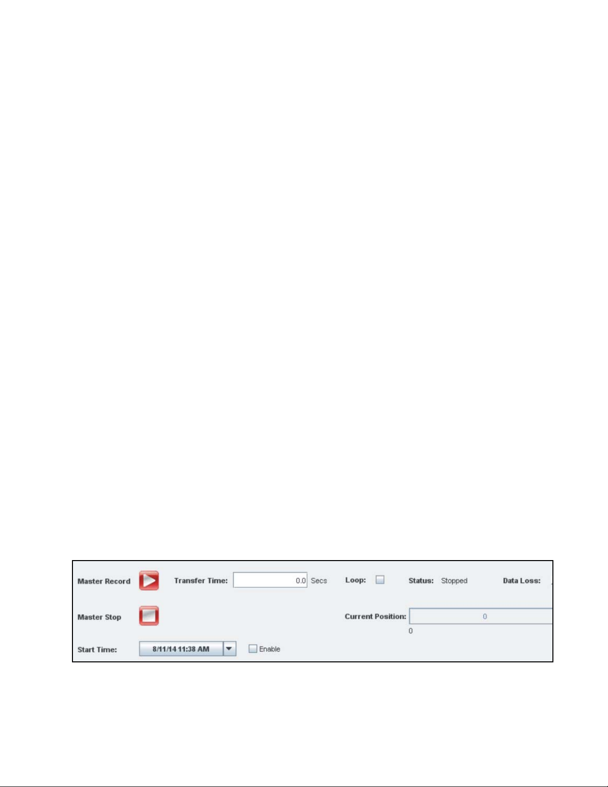
Talon RTS 2706 Operating Manual Page 39
6.3 Master Record Controls (continued)
6.3.7 Master Current Position (Secs)
The current recording position within the file is shown in seconds. When the
recording is stopped manually or automatically, the Current Position field
displays the total duration of the recording.
6.3.8 Record GPS Position
This check box determines whether the GPS position is recorded. By default,
Talon recording systems that have the GPS option will automatically record
the GPS position (write it to the header file). However, if you do not want
the Talon system to record this information, simply uncheck this check box.
When you save a profile, the state of this check box will be saved, so you can
set this option as enabled or disabled beforehand. If your system does not
have the GPS option, this box will not appear on the record screen.
6.3.9 Signal Viewer
The Signal Viewer button launches the Talon Signal Viewer for preview or
monitoring of the signals before or during recording. See Chapter 9 for more
details.
6.3.10 Programmable Recording Start Time
The SystemFlow software allows you to set a date and time at which record−
ing will start automatically, thus eliminating the need for someone to start
the recorder manually. Figure shows the Start Time field on the System−
Flow Record screen. When you specify a time in this field and put a check
mark in the Enable checkbox, recording will start automatically at the time
you specified.
Figure 6−4: Start Time
Rev.: 3.2

Page 40 Talon RTS 2706 Operating Manual
This page is intentionally blank
Rev.: 3.2

Talon RTS 2706 Operating Manual Page 41
Chapter 7: Recorded Data Format
The Talon system records data to disk as a binary file. This file contains a header that is
1024 bytes in size and is immediately followed by the recorded data. The Pentek boards
used in the Talon system present this data as raw twos−complement data.
This header contains important information about the recording that can be used to
process and analyze the data. The recorded data resides in the file as contiguous data as
streamed by the I/O interface. This data is written by default in little−endian format.
Table 7−1 provides details about the file header.
The File Viewer, described in Chapter 10 uses this file header information to display
information about the recording and for scaling the displays.
7.1 IF data
The IF data provided by the DDC is recorded as “Packed I/Q” data, where I and Q are
each 16−bit values.
This data is provided by default in the following format.
Bits D15 to D00 − I data
Bits D31 to D15 − Q data
7.2 Baseband data
The baseband data provided by the ADC is recorded as time−packed data, where each
64−bit word contains four consecutive 16−bit samples.
This data is provided by default in the following format:
• The first sample, at time ‘t’, is placed into bits 15 to 0.
• The next sample, at time ‘t+1’, is placed into bits 31 to 16.
• The next sample, at time ‘t+2’, is placed into bits 47 to 32.
• The next sample, at time ‘t+3’, is placed into bits 63 to 48.
Rev.: 3.2

Page 42 Talon RTS 2706 Operating Manual
7.3 File Header Format
Table 7−1 below shows the format of the file header, with a brief description of each of
the fields in the header.
Table 7−1: Talon File Header Format
Offset
0x0 Model Number int_32 The Talon model number (0x27060000 for Model 2706).
0x4 File Name char[256] The name of the recorded file.
0x104 File Size (in MSs) int_32
0x108 File Size (in secs) float_32 The length of the recording, in seconds.
0x10C Time Stamp char[32]
0x12C Reserved char[256] Factory Reserved.
0x22C Buffer Size int_32 The buffer size used by the recorder, in bytes.
0x230 Data Rate (in MS/s) float_32
0x234 Data Loss int_32 Data loss indicator. 0 = no data lost. 1 = data lost.
0x238
0x23C Data Type int_32 0 = Raw A/D samples. 1 = DDC Complex I/Q data.
0x240 Packing Mode int_32
0x244 Rate Divider int_32
0x248 Input Voltage Level int_32 The full scale input voltage level: 2 = 8 dBm.
0x24C
0x250
0x254 Decimation int_32 For IF recordings only, the decimation of the DDC.
0x258 Reserved int_32 Factory Reserved.
0x25C Reserved int_32 Factory Reserved.
0x260 Board Number int_32 Board Model 786610 = 0x78661000.
0x264 Reserved int_32 Factory Reserved.
0x268 Reserved int_32 Factory Reserved.
0x26C Reserved int_32 Factory Reserved.
0x270 Reserved int_32 Factory Reserved.
0x274 Channel Number int_32 The channel number in the system.
0x278 Reserved int_32 Factory Reserved.
0x27C Reserved int_32 Factory Reserved.
0x280
0x288 ADC Resolution int_32 The number of bits of resolution in the A/D converter.
Data Offset (in
bytes)
Sampling Rate (in
MHz)
Tuning Frequency
(in MHz)
Last Good Data
Location
Field
Data
Type
The size of the file in MSs (not including the header). The
total amount of data written in the recording.
The recording time stamp. See Time Stamp Field on page
44.
The calculated data rate of the recording in megasamples
(millions of samples) per second.
int_32
float_32 The sampling rate of the A/D converter, in MHz.
float_32
int_64
The offset into the file where the recorded data resides −
for legacy use only.
Packing Mode. 1 = 8−bit packed data, 2 = 16−bit packed
data, 3 = 32−bit packed data.
For baseband recordings only, the rate divider applied to
the sample clock.
For IF recordings only, the tuning frequency of the DDC, in
MHz.
If data loss occurs, this field represents the amount of
good data available prior to any real−time data loss.
Description
Rev.: 3.2

Talon RTS 2706 Operating Manual Page 43
Table 7−1: Talon File Header Format (Continued)
Offset
0x28C GPS Latitude float_32
0x290 GPS Longitude float_32
0x294 GPS Altitude float_32
0x298
0x2A0 File Size (in MSs) float_32
0x2A4 RF Tuner Gain double_64
0x2A8 User Defined 1 int_32 User−defined field.
0x2AC User Defined 2 int_32 User−defined field.
0x2B0 User Defined 3 int_32 User−defined field.
0x2B4 User Defined 4 int_32 User−defined field.
0x2B8 User Defined 5 int_32 User−defined field.
0x2BC User Defined 6 int_32 User−defined field.
0x2C0 User Defined 7 int_32 User−defined field.
0x2C4 User Defined 8 int_32 User−defined field.
0x2C8 User Defined 9 int_32 User−defined field.
0x2CC User Defined 10 int_32 User−defined field.
0x2D0 Start Frequency double_64
0x2D8 Stop Frequency double_64
0x2E0 Step Size float_32
0x2E4 Number of Steps int_32
0x2E8 Dwell Time (in ms) float_32
0x2EC
0x2F0 Total Time (in ms) float_32
0x2F4
0x2F8 Input Impedance int_32 The impedance of the channel, in ohms.
0x2FC Reserved int_32 Field used in Ethernet recorders only.
0x300 Reserved int_32 Field used in Ethernet recorders only.
0x304 Reserved int_32 Field used in Ethernet recorders only.
0x308 Reserved int_32 Field used in Ethernet recorders only.
RF Tuning
Frequency
Transient Time (in
ms)
System Revision
Number
Field
Data
Type
double_64
float_32
int_32
Description
GPS latitude, in degrees. For systems that include the
optional GPS receiver.
GPS longitude, in degrees. For systems that include the
optional GPS receiver.
GPS altitude, in meters. For systems that include the
optional GPS receiver.
RF Tuning Frequency, in MHz (used for supported RF
Tuners modules).
File Size in MSs (not including the header). The total
amount of data written in the recording.
RF Tuning Frequency, in dB (used for supported RF tuner
modules).
64−bit scanner start frequency, in GHz. (Used for
supported RF tuner modules.)
64−bit scanner stop frequency, in GHz. (Used for
supported RF tuner modules.)
Size of the steps in the scan, in MHz. (Used for supported
RF tuner modules).
The number of steps in the scan. (Used for supported RF
tuner modules).
Time to dwell in each bin, in milliseconds. (Used for
supported RF tuner modules.)
Time in between dwells, in milliseconds. (Used for
supported RF tuner modules.)
Total scan time (in milliseconds) = [(dwell time + transient
time) x numBins] (Used for supported RF tuner modules.)
Revision number in hex. The upper 16 bits correspond to
the major revision number. The lower 16 bits correspond
to the minor revision number. For example, 0x00020004 =
Revision 2.4.
Rev.: 3.2

Page 44 Talon RTS 2706 Operating Manual
Table 7−1: Talon File Header Format (Continued)
Offset
0x334 Number of Files int_32
0x33C
0x340
Start File Index (in
bytes)
Data Offset (in
bytes)
Field
Data
Type
int_32
int_64 The offset into the file where the recorded data begins.
Time Stamp Field
The Time Stamp field’s format is as follows:
Month/Day/Year Hrs:Mins:Secs:mSecs
For example:
04/21/2013 11:28:07:086
NOTE: In systems with the GPS timestamp option, the time field is
extended by three additional digits of precision. For example,
11:28:07:086492 provides 100 ns resolution.
Description
For segmented recording: the number of files used for the
entire recording.
For looped segmented recording: The file index where the
recording begins.
Rev.: 3.2

Talon RTS 2706 Operating Manual Page 45
Chapter 8: Playing a Recorded File
This chapter describes how to play a recorded file:
• Section 8.1 describes the Play screen.
• Section 8.2 describes the play channel controls.
• Section 8.3 describes the master play controls.
NOTE:
The Play tab is only provided if your Talon system has a playback option.
8.1 The Play Screen
Select the Play Screen by clicking on the Play tab along the top of the GUI. Figure 8−1
shows an example of the Play screen. The available channels are shown in the Channel
column on the bottom left of the screen. The Play screen configures the playback
modes, length and starting position of playback, and file names.
Figure 8−1: Play Screen
The top section of the Play screen allows you to play multiple channels and the bottom
section allows you to play a single channel.
Rev.: 3.2

Page 46 Talon RTS 2706 Operating Manual
8.2 Play Channel Controls
After recording to disk, you can play back any of the recorded files. The bottom section
of the Play screen (shown in Figure 8−1) contains the play controls . This section lets
you enter the filename for each channel to be played back, set the recording transfer
length, start and stop the recording, and monitor the status of the recording.
Figure 8−2: Play Screen: Channel Controls
8.2.1 File Name and Browse
The name of the file to be played back is entered in the text entry window
under File Name adjacent to the appropriate resource. Alternately, you can
click on the Browse button to locate a file using a file directory window. The
extension of the played file must be .dat. The full path, including the drive
letter, must be included with the file name.
8.2.2 Start Position
The starting position of the playback file in seconds or megasamples can be
entered in the numeric entry window under Start Position. If the Start
Position equals 0.0 secs or 0 MSs, then the playback starts at the beginning
of the file. If the Start Position exceeds the length of file in time, then an
error message appears: <servername>: File too small
8.2.3 Play Until Manual Stop
You can choose to play a signal until the Stop button is pressed, by entering
a file transfer length or file transfer time of 0 in the Transfer Length field.
Rev.: 3.2
NOTE:
If you don't manually press Stop, playback will stop automatically
at the end of the file.

Talon RTS 2706 Operating Manual Page 47
8.2 Play Channel Controls (continued)
8.2.4 Play by Time
For time length playback, set the units selection menu to Secs (seconds).
(This menu is to the right of the numeric entry field in the Transfer Length
column). Then specify the number of seconds for the playback using the
numeric entry field under Transfer Length.
This entry accepts a floating point value, allowing you to specify resolutions
smaller than 1 second. After the playback starts, it will automatically stop
after the elapsed time specified.
NOTE:
The minimum play time is 1 millisecond. If the number of MSs
represents a play time of under 1 millisecond, you will be
prompted accordingly. If play time exceeds the file size, playback
will stop at the end of the file.
8.2.5 Play by File Size
For file size length playback, set the units selection menu to MSs (Megasam−
ples). (This menu is to the right of the numeric entry field in the Transfer
Length column). Then specify the number of Megasamples for the playback
using the numeric entry window under Transfer Length. After the playback
starts, it will automatically stop after the file size reaches the specified limit.
NOTE:
The minimum play time is 1 millisecond. If the number of MSs
represents a play time of under 1 millisecond, you will be
prompted accordingly. If play time exceeds the file size, playback
will stop at the end of the file.
8.2.6 Loop
If the Loop box is unchecked, files will be played back for the requested
amount of time or length and then playback will stop. If the Loop box is
checked, files will be played back repeatedly, looping back to the Start Posi−
tion after the requested transfer time or length. The Loop box is toggled
between checked and unchecked by clicking on it with the mouse.
Loop must be selected before beginning the playback. If the Loop box is
checked and then the playback begins, it cannot be unchecked during play−
back, and vice−versa.
Rev.: 3.2

Page 48 Talon RTS 2706 Operating Manual
8.2 Play Channel Controls (continued)
8.2.7 Master Play
The Master Play checkboxes allow multiple channels to be played back
simultaneously. Channels can be selected for Master Play by clicking on the
box to show a check mark. Channels can be de−selected from Master Play by
clicking on the box to remove the check mark. See Section 8.3 for more
details.
8.2.8 Play Button
The playback can be manually started for each channel by clicking its Play
button.
8.2.9 Stop Button
The playback can be manually stopped for each channel by clicking its Stop
button.
8.2.10 Status
The Status column will display Stopped or Playing, reflecting the current
operating mode.
8.2.11 Channel Position (MSs)
The Channel Position column shows the current playback position within
the file in megasamples. When the playback is stopped manually or auto−
matically, this field displays the last position of the playback.
8.2.12 Data Rate (MS/s)
During playback, the Data Rate column shows the current playback data
rate in megasamples per second. When playback is stopped manually or
automatically, this field displays the final playback rate.
Rev.: 3.2

Talon RTS 2706 Operating Manual Page 49
8.2 Play Channel Controls (continued)
8.2.13 Data Loss
The Data Loss indicator will light up red if data cannot be played back from
a file. If the Data Loss indicator is not lit, then all of the data was played
back successfully.
Data loss is flagged by the recorder when any condition that results in a dis−
continuity of the data stream occurs. The Talon recording system flags this
data loss in both the real−time status as well as in the recording’s file header.
The file header also includes a field that contains the location of the last
good (contiguous) data recorded, so the operator can use the portion of the
recording that is still good.
Data loss can happen for a number of reasons. Any time that the storage
drives fail to keep up with the real−time stream of data from either A/D
converters or a digital interface will result in a real−time data loss. This
could happen if the system parameters are set up in a way that results in a
higher aggregate data rate to disk than the system can handle. The following
are other potential causes of data loss:
• In Talon RTS systems, the performance of the HDDs could be affected by
a momentary shock or an environment of high vibration, resulting in
data loss. (Talon RTR and RTX systems have SSDs, which are not
affected in this way.)
• An almost full or highly fragmented disk could result in data loss.
• Selecting the wrong drive to record each file to will often result in data
loss.
• Failure to apply an external clock when specifying one.
• Incorrectly setting up an external trigger.
• Specifying incorrect clock rates, decimation rates, bandwidths, or other
system settings.
The operator should consider all of these possibilities when observing data
loss and take care to create an environment that results in error−free record−
ing every time.
Rev.: 3.2

Page 50 Talon RTS 2706 Operating Manual
8.3 Master Play Controls
The master play controls are located at the top of the Play screen (see Figure 8−3). These
controls allow simultaneous multi−channel playback.
The Master Play checkboxes in the channel controls section at the bottom of the Play
screen (Figure 8−1) select or deselect channels for Master Play.
To select a channel for Master Play, click on its Master Play box to show a check mark.
To de−select a channel from Master Play, click on the box to remove the check mark.
All the channels selected for Master Play are controlled by the settings in the Master
Controls section.
Figure 8−3: Play Screen − Master Controls
8.3.1 Master Play Button
The master playback can be manually started for all selected channels by
clicking the Master Play button.
8.3.2 Master Stop Button
The master playback can be manually stopped for all selected channels by
clicking the Master Stop button.
8.3.3 Play Until Manual Stop − Master Playback
You can choose to master play all selected channels until you manually
press the Stop button by entering a file transfer length or file transfer time of
0 in the Transfer Time field.
NOTE:
If you don't manually press Stop, playback will stop automatically
at the end of the file.
Rev.: 3.2

Talon RTS 2706 Operating Manual Page 51
8.3 Master Play Controls (continued)
8.3.4 Play by Time − Master Playback
For time−length master playback, set the Transfer Time numeric entry field
to the number of seconds desired for master playback. After the playback
starts, playback of all master−controlled channels will automatically stop
after the elapsed time specified.
NOTE:
The minimum play time is 1 millisecond. If play time exceeds file
size, playback stops at the end of the file.
8.3.5 Master Status
The master play Status field will display Stopped or Playing, reflecting the
current master playback operating mode.
8.3.6 Master Data Loss
The Data Loss indicator will light up red if data in any of the master play−
back channels is not played back successfully from a file. This can happen if
the recording is corrupted, or for other reasons.
If the Data Loss indicator is not lit, then all of the data for all master play−
back channels was played back successfully.
8.3.7 Master Current Position (Secs)
The Current Position indicator shows the current playback position within
the file in seconds. When playback is stopped manually or automatically,
this field displays the total duration of the file.
8.3.8 File Viewer
The File Viewer button selects the File Viewer for displaying the signals
after recording. See Chapter 10 for more details.
Rev.: 3.2

Page 52 Talon RTS 2706 Operating Manual
This page is intentionally blank
Rev.: 3.2

Talon RTS 2706 Operating Manual Page 53
Chapter 9: Monitoring Input Signals with Signal Viewer
This chapter describes the Talon recording system’s Signal Viewer:
• Section 9.1 provides an overview of the Signal Viewer.
• Section 9.2 describes the Signal Viewer display windows and display controls.
• Section 9.3 describes the Signal Viewer input controls.
• Section 9.4 describes the data displayed on the Signal Viewer.
9.1 Introduction: the Signal Viewer
The Talon Signal Viewer allows you to monitor live input signals before and during
recording, in both time and frequency domains. It provides a wealth of signal analysis
tools, including amplitude and frequency calculators, distortion calculators, averaging
modes, zooming and panning controls, and cursors for exploring spectral components.
Signals displayed on the Signal Viewer are “snapshot” blocks of data, processed by the
signal viewer at its maximum rate:
• If the data rate into the viewer is faster than the viewer can process input samples,
then input data is discarded until the viewer can accept another new block of
samples.
• If the data rate into the viewer is slower than the viewer processing speed, then the
viewer will wait for a complete block of samples before updating the Time and
Frequency displays, and no input data is discarded.
The Signal Viewer is launched from the Signal Viewer button in the upper right corner
of the Record Screen (Figure 6−1), or the Play Screen (Figure 8−1).
Rev.: 3.2

Page 54 Talon RTS 2706 Operating Manual
9.2 Signal Viewer Displays and Display Controls
The Signal Viewer presents two display windows: the Time window on the left and the
Frequency Magnitude window on the right as shown in Figure 9−1.
Rev.: 3.2
Figure 9−1: Signal Viewer (Default Display)
At the bottom of the Time window is a Samples switch that allows you to select
between samples and time (Figure 9−2).
Figure 9−2: Samples/Time Switch
Click on the switch to change its position/setting. When the switch is set to Samples,
the X−axis is scaled to show the signal in terms of the number of samples. When
switched to Time, the X−axis is scaled to show the signal in terms of time in seconds.

Talon RTS 2706 Operating Manual Page 55
9.2 Signal Viewer Displays (continued)
On the left side of the Time window is an Amplitude switch (Figure 9−3) that allows
you to toggle the amplitude scaling between Volts and % of Full Scale. Click on the
switch to change its position/setting.
Figure 9−3: Amplitude Switch (Time Display)
At the top of the Time window is a Display Type switch (Figure 9−4). The Display
Type switch allows you to toggle the left−side Signal Viewer window between the
Time display and the Frequency − Time − Intensity display. Click on the switch to
change its position/setting.
Figure 9−4: Display Type Switch
Figure 9−1 shows the Signal Viewer with the Time display in the left window and
Figure 9−5 shows the Signal Viewer with the Frequency − Time − Intensity display in
the left window.
Rev.: 3.2

Page 56 Talon RTS 2706 Operating Manual
9.2 Signal Viewer Displays (continued)
When the Display Type switch is set to show Frequency − Time − Intensity, the left
window displays a horizontal waterfall of the signal that is shown in the right window.
See Figure 9−5. The color corresponds to the intensity of the signal.
Figure 9−5: Signal Viewer with Frequency−Time−Intensity Display in Left Window
Regardless of what is displayed in the Signal Viewer’s left window, the Signal Viewer’s
right window always shows the Frequency Magnitude display. On the left side of the
Frequency Magnitude window is an Amplitude switch (Figure 9−6) that allows you to
toggle the amplitude scaling between dBm and dBfs. Click on the switch to change its
position/setting
Figure 9−6: Amplitude Switch (Frequency Magnitude Display)
The Signal Viewer has various controls that allow you to adjust the display. These are
described in Chapter 11.
Rev.: 3.2

Talon RTS 2706 Operating Manual Page 57
9.3 Input Controls
This section described the controls that enable you to adjust the input.
9.3.1 Resume, Pause and Close
When started, the Signal Viewer begins displaying live data. Clicking on the
Pause button in the lower left stops the live display and clicking Resume
restarts it. The Signal Viewer is closed by clicking the Close button.
Figure 9−7: Resume, Pause and Close Buttons
9.3.2 Channel Index and Board Index
The Channel Index up/down buttons (Figure 9−8) in the lower left of the
screen allow you to select a port or channel for signal viewing. Each port or
channel in your system is assigned a number, which is shown on the Talon
system’s main configuration screen (Figure 5−1).
If your system uses more than one board, the Board Index up/down but−
tons (Figure 9−8) allow you to select the board that is generating the signals
you want to view. The Board Index number is the last digit shown on the
board tab shown on the channel configuration panel on the main configura−
tion screen (see Figure 5−1).
Figure 9−8: Channel Index and Board Index
9.3.3 FFT Size
By clicking on the FFT size input field you will be able to choose from sev−
eral specified values, ranging from 128 to 64K.
Figure 9−9: FFT Size
Rev.: 3.2

Page 58 Talon RTS 2706 Operating Manual
9.3 Input Controls (continued)
9.3.4 Spectrum Averaging
The Averaging control on the bottom right side of the screen provides expo−
nential averaging of the frequency spectrum display. The number of aver−
ages is set with an up/down button, or with direct numeric entry.
For an averaging value of N, exponential averaging sums the latest N values
for each frequency display point (FFT point) and divides each value by N.
The larger the value of N, the more averaging occurs.
If the Peak Hold button is pressed, the right−hand window will display the
peak amplitudes across all the bandwidths.
Figure 9−10: Averaging Control
9.3.5 Baseband / IF Frequency Scale
Signals translated by the DDCs from an IF frequency down to baseband can
be displayed with the frequency indicator showing either the original IF
frequency (default) or the down−converted Baseband frequency. The IF
toggle switch is changed by clicking on it. When you toggle the switch, the
label on the switch will change back and forth from IF to Baseband.
Figure 9−11: Baseband / IF Frequency Scale Control
NOTE:
This feature is only available for DDC output signals.
Rev.: 3.2

Talon RTS 2706 Operating Manual Page 59
9.4 Data Displayed
9.4.1 System, Server and Board Model
The lower center portion of the screen shows the Talon System model num−
ber, the IP address of the Server, and the Pentek software radio Board
Model (Figure 9−12).
Figure 9−12: Example of System, Server, and Board Model Fields
9.4.2 Signal Characteristics
In order for the Signal Viewer to properly scale signals that are being
acquired by the Talon recorder, it is necessary to provide information about
the acquisition setup.
• In the case of an Analog Talon signal recorder, information about the
setup of the A/D converters and other pertinent information is passed to
the Signal Viewer via a control word to allow for automatic time and
frequency domain signal scaling.
• In the case when real world signals are digitized by an external device
and then sent to and recorded by a Digital Talon signal recorder, you
can still display these signals in the viewer you but must manually set
up the scaling via the GUI.
In order to manually set up the scaling, you must click on the Control switch
shown in Figure 9−13 to switch it from Auto to Manual. Once in Manual
mode, the viewer allows you to input values for the Channel Type, Packing
Mode, Clock, Center Frequency, and Decimation. Setting these to match
your signal acquisition settings will result in the proper scaling in both the
Time and Frequency domain windows. Additionally, the numeric value
displayed in the Frequency detection window should accurately show the
frequency of the primary tone being acquired.
Figure 9−13: Signal Characteristics
Rev.: 3.2

Page 60 Talon RTS 2706 Operating Manual
9.4 Data Displayed (continued)
9.4.3 Amplitude Calculator
The Amplitude calculator window in the lower left of the Signal Viewer
displays the calculated amplitude of the input signal in dBm, VRMS, and
V(p−p).
Figure 9−14: Amplitude Calculator
dBm dBm = 20 log (V
where 0.2236 = the RMS Voltage of l mW
V
RMS
V
calculates the root mean square of the input signal.
RMS
) − 20 log (0.2236)
RMS
RMS
into 50
V(p−p) V(p−p) measures the difference from the most positive peak to
the most negative peak.
NOTE:
The Overload LED corresponds to the Overload LED on the actual
board that is used in your Talon system. See Chapter 3.
Rev.: 3.2

Talon RTS 2706 Operating Manual Page 61
9.4 Data Displayed (continued)
9.4.4 Distortion Calculator
The distortion calculator window located to the right of the Amplitude Cal−
culator displays the results of signal analysis algorithms.
Figure 9−15: Distortion Calculator
• 2nd Harmonic − Displays the level of the second harmonic component
in dB relative to the fundamental signal level.
• 3rd Harmonic − Displays the level of the third harmonic component in
dB relative to the fundamental signal level.
• SINAD − Displays the measured signal noise and distortion (SINAD).
SINAD is defined as the dB ratio of the RMS energy of all signals to the
RMS energy of all signals minus the energy of the fundamental.
• THD − Displays the measured total harmonic distortion up to and
including the highest harmonic component. THD is defined as the ratio
of the RMS sum of the harmonic components to the amplitude of the
fundamental signal. To compute THD as a percentage, multiply the
displayed value by 100.
9.4.5 Resolution Bandwidth Calculator
The resolution bandwidth calculator located to the right of the signal char−
acteristics panel displays the resolution bandwidth based on the frequency
bandwidth and FFT size.
Figure 9−16: Resolution Bandwidth Calculator
Rev.: 3.2

Page 62 Talon RTS 2706 Operating Manual
This page is intentionally blank
Rev.: 3.2

Talon RTS 2706 Operating Manual Page 63
Chapter 10: Analyzing Recorded Signals with File Viewer
This chapter describes the Talon recording system’s File Viewer:
• Section 10.1 provides an overview of the Signal Viewer.
• Section 10.2 lists the differences between the Signal Viewer and the File Viewer.
• Section 10.3 describes how to select a file to view.
• Section 10.4 describes the display and playback controls.
• Section 10.5 describes the data displayed on the file viewer.
• Section 10.6 describes the data extraction utility.
10.1 Introduction: the File Viewer
The Talon system’s File Viewer allows you to analyze recorded signals stored on disk
in both time and frequency domains. It is nearly identical to the Signal Viewer
described in Chapter 9 and includes the same wealth of signal analysis tools, including
amplitude and frequency calculators, distortion calculators, averaging modes, zoom
and panning controls, and cursors for exploring spectral components. Many of the fol−
lowing sections are identical to those in Chapter 9.
The File Viewer is launched from File Viewer button in the upper right corner of the
Play screen as shown in Figure 8−1.
10.2 Differences Between the Signal Viewer and the File Viewer
Differences between the Signal Viewer and the File Viewer are as follows:
• The Signal Viewer Pause/Resume button is replaced with the File Viewer Play/
Resume button.
• The Signal Viewer Close button is replaced with the File Viewer Quit button.
• The Signal Viewer System−Server−Board windows is replaced with the File Server
Board−System−Time Stamp window
• The Signal Viewer Baseband/IF switch is replaced with the File Viewer Playback
Speed/All Data switch.
Rev.: 3.2

Page 64 Talon RTS 2706 Operating Manual
10.2 Differences Between the Signal Viewer and the File Viewer (continued)
•The Signal Viewer Channel Type and Channel Number window is replaced with the
Playback Controls window.
• The File Viewer includes a Data Extraction Utility (see Section 10.6).
Signals displayed on the Signal Viewer are live signals, so if the viewer cannot keep up
with the live input rate, data is not displayed.
Signals displayed on the File Viewer are read from disk files so it is possible to display
all data at the rate the viewer can process the data. If data was recorded at a high sam−
ple rate, and all data is displayed, the File Viewer will display the data more slowly
than it was recorded.
However, an optional mode of the File Viewer allows the display rate to match the
original recording rate by discarding blocks of data it cannot keep up with. This is
described below in Section 10.4.3.
10.3 Selecting a File to View
The File Viewer is launched from File Viewer button in the upper right corner of the
Play screen as shown in Figure 8−1.
After the File Viewer is launched, you must select a file to view. Locate the Playback
Controls window on the lower left portion of the screen. Figure 10−1 shows this por−
tion of the File Viewer.
Figure 10−1: Playback Controls
To select a file to view, click on the file folder icon (located under the Quit button). The
Select the Data File to View file browse screen appears as shown in Figure 10−2. Use
this screen to browse to the file for display, or enter the path and file name in the File:
data entry field.
Rev.: 3.2

Talon RTS 2706 Operating Manual Page 65
10.3 Selecting a File to View (continued)
Figure 10−2: File Viewer File Selection Browser
Rev.: 3.2

Page 66 Talon RTS 2706 Operating Manual
10.4 Display and Playback Controls
After you select a file to view, the File Viewer presents two display windows: the Time
window on the left and the Frequency Magnitude window on the right, as shown in
Figure 10−3.
Rev.: 3.2
Figure 10−3: Example of File Viewer
At the bottom of the Time window is a switch that allows you to select between sam−
ples and time. When the switch is set to Samples, the X−axis is scaled to show the sig−
nal in terms of the number of samples. When switched to Time, the X−axis is scaled to
show the signal in terms of time in seconds.
10.4.1 Display Controls
The File Viewer has various controls that allow you to adjust the display.
These are described in Chapter 11.
10.4.2 Playback Controls
When started, the File Viewer waits for you to click the Play button on the
lower left side of the screen to start the display. Clicking on the Pause button
stops the file display and clicking Play restarts it. The File Viewer is closed
by clicking the Quit button. See Figure 10−4.

Talon RTS 2706 Operating Manual Page 67
10.4 Display and Playback Controls (continued)
10.4.2 Playback Controls (continued)
Figure 10−4: Play, Pause and Quit buttons
The playback controls section on the lower left side of the screen provides a
file position slider progress indicator that shows the approximate playback
position of the file. The slider can be moved left or right to quickly change
the playback position.
The playback controls window (Figure 10−1) shows the exact playback
position of the file in seconds. You can adjust the current position of the file
position display by using the up/down button or entering a numeric value
directly into the field.
10.4.3 Playback Speed
Signals displayed on the Signal Viewer are live signals, so if the viewer
cannot keep up with the live input rate, data is not displayed, as discussed
in Section 9.1. Signals displayed on the File Viewer are read from a disk file
so it is possible to display all data at the rate the viewer can process the data.
If data was recorded at a high sample rate, and all data is displayed, the File
Viewer will display the data more slowly than it was recorded.
On the other hand, you may wish to display the recorded data at the same
rate it was recorded (Real−Time), like the live display in the Signal Viewer.
The Playback Speed switch allows you to choose the mode of playback.
This switch is part of the Playback Controls (see Figure 10−1).
Figure 10−5: Playback Speed Switch
When the switch is pointing towards Real−Time (which means Real−Time
is turned on), recorded data will be displayed at the rate it was recorded, but
some data may be discarded, similar to the Signal Viewer operation.
When Real−Time is turned off (the switch is not pointing towards Real−
Time), all recorded data will be displayed as fast as the viewer can present
it. In this mode, it may take longer to view the recording than the original
duration of the recording, but no data will be discarded. The switch is tog−
gled by clicking it with the mouse.
Rev.: 3.2

Page 68 Talon RTS 2706 Operating Manual
10.4 Display and Playback Controls (continued)
10.4.3 Playback Speed (continued)
Since digital recorders do not always provide data at a constant data rate,
the Playback Speed switch often does not have the same effect for digital
recorders as it does with a Talon Analog Recording System. Because A/D
converters sample data at a constant rate, the Real−Time playback switch
can be calibrated to replicate the real−time flow of data. This is not always
effective with digital recording systems and therefore this switch may not
prove useful in some systems.
10.4.4 Spectrum Averaging
The Averaging control provides exponential averaging of the frequency
spectrum display. The number of averages is set with an up/down button,
or with direct numeric entry.
For an averaging value of N, exponential averaging sums the latest N values
for each frequency display point (FFT point) and divides each value by N.
The larger the value of N, the more averaging occurs.
Figure 10−6: Exponential Averaging Control
Rev.: 3.2

Talon RTS 2706 Operating Manual Page 69
10.5 Data Displayed
10.5.1 Board, System, Time Stamp, and Optional GPS
The lower right section of the window shows the Board identifier, the Sys−
tem identifier, and the Time Stamp. The GPS Longitude, GPS Latitude,
and GPS Altitude will also be displayed if your Talon system has the GPS
option. All of these parameters were stored in the file header when the file
was recorded.
Figure 10−7: Board, System, Time Stamp, and Optional GPS
10.5.2 Signal Characteristics
In order for the File Viewer to properly scale signals that are being acquired
by the Talon recorder, it is necessary to provide information about the
acquisition setup.
• In the case of an Analog Talon signal recorder, information about the
setup of the A/D converters and other pertinent information is obtained
by the File Viewer via the data recording’s file header to allow for
automatic time and frequency domain signal scaling.
• In the case when real world signals are digitized by an external device
and then sent to and recorded by a Digital Talon signal recorder, you
can still display these signals in the viewer you but must manually set
up the scaling via the GUI.
In order to manually set up the scaling, you must click on the Control switch
shown in Figure 10−8 to switch it from Auto to Manual. Once in Manual
mode, the viewer allows you to input values for the Channel Type, Packing
Mode, Clock, Center Frequency, and Decimation. Setting these to match
your signal acquisition settings will result in the proper scaling in both the
Time and Frequency domain windows. Additionally, the numeric value
displayed in the Frequency detection window should accurately show the
frequency of the primary tone that was acquired.
Figure 10−8: Signal Characteristics
Rev.: 3.2

Page 70 Talon RTS 2706 Operating Manual
10.5 Data Displayed (continued)
10.5.3 Distortion Calculator
The distortion calculator window located to the right of the amplitude cal−
culator displays the results of signal analysis algorithms on the recorded
signal.
Figure 10−9: Distortion Calculator
• 2nd Harmonic − Displays the level of the second harmonic component
in dB relative to the fundamental signal level.
• 3rd Harmonic − Displays the level of the third harmonic component in
dB relative to the fundamental signal level.
• SINAD − Displays the measured signal noise and distortion (SINAD).
SINAD is defined as the dB ratio of the RMS energy of all signals to the
RMS energy of all signals minus the energy of the fundamental.
• THD − Displays the measured total harmonic distortion up to and
including the highest harmonic component. THD is defined as the ratio
of the RMS sum of the harmonic components to the amplitude of the
fundamental signal. To compute THD as a percentage, multiply the
displayed value by 100.
Rev.: 3.2

Talon RTS 2706 Operating Manual Page 71
10.5 Data Displayed (continued)
10.5.4 Amplitude Calculator
The Amplitude calculator window in the lower left of the Signal Viewer
displays the calculated amplitude of the input signal in dBm, VRMS, and
V(p−p).
Figure 10−10: Amplitude Calculator
dBm dBm = 20 log (V
where 0.2236 = the RMS Voltage of 1 mW
V
RMS
V
calculates the root mean square of the input signal.
RMS
) − 20 log (0.2236)
RMS
RMS
into 50
V(p−p) V(p−p) measures the difference from the most positive peak to
the most negative peak.
Rev.: 3.2

Page 72 Talon RTS 2706 Operating Manual
10.6 Data Extraction Utility
The Data Extraction Utility (Figure 10−12) enables you to extract sections of interest
from your recording. This utility allows you to mark a starting point and an ending
point in the original recording and copy that data to a new file. In addition to the
extracted data, the new file will include the same header information as the original
recording.
To use the Data Extraction Utility, move the file position in the Playback Controls
(Figure 10−11) to the start position of the section you want to copy.
Figure 10−11: Playback Controls
After you set the start position, click the Start Marker button on the Data Extraction
Utility (Figure 10−12). Next, move the file position in the Playback Controls to the end
of the section you want to copy. Click the Stop Marker button on the Data Extraction
Utility to set the end position.
Figure 10−12: Data Extraction Utility
To select a name for the data extraction file, click on the folder browse button (folder
icon) on the Data Extraction Utility and enter a file name.
To begin data extraction, click the Start button. The file extraction's progress will be
indicated as the MBs field increments throughout the transfer. This will stop once the
file transfer is complete. If you wish to manually stop the transfer at any time, click the
Stop button.
Rev.: 3.2

Talon RTS 2706 Operating Manual Page 73
Figure 11−2: Time and FFT (Frequency) Display Controls
Chapter 11: Display Controls for Signal and File Viewer
This chapter describes the controls related to the display of data:
• Sections 11.1 and 11.2 describe display zooming and panning.
• Section 11.3 describes how to reset the scale of the time and frequency displays.
• Section 11.4 describes cursor operation.
11.1 Display Zooming
The Time Display Controls and FFT Display Controls both include Zoom buttons
(center button) to provide tools for zooming in both the Time and Frequency display
windows (see Figure 11−1).
Figure 11−1: Time and FFT (Frequency) Display Controls
Click on the magnifying glass Zoom button to invoke the zoom function for either
the Time or Frequency (FFT) display window.
The Zoom menu screen appears as shown in Figure 11−2. Click on any one of the six
buttons in the menu to invoke the desired zoom functions described in the following
paragraphs. Zooming will change the horizontal or vertical scale, or both.
Rev.: 3.2

Page 74 Talon RTS 2706 Operating Manual
11.1 Display Zooming (continued)
11.1.1 Horizontal Zoom
To zoom in the horizontal axis only, click the Horizontal Zoom button (see
Figure 11−2). Then place the magnifying glass cursor in the display window
at the starting position for horizontal zoom, hold the left mouse button
down, drag the cursor to the ending position for the horizontal zoom, and
then release the mouse button.
11.1.2 Vertical Zoom
To zoom in the vertical axis only, click the Vertical Zoom button (see Figure
11−2). Then place the magnifying glass cursor in the display window at the
starting position for vertical zoom, hold the left mouse button down, drag
the cursor to the ending position for the vertical zoom, and then release the
mouse button.
11.1.3 Windowed Zoom
To zoom within a rectangular window, click the Windowed Zoom button
(see Figure 11−2). Then place the magnifying glass cursor in the display
window in one corner of the desired zoom rectangle, hold the left mouse
button down, drag the cursor to the opposite corner of the desired zoom
rectangle, and then release the mouse button.
11.1.4 Full Screen
To restore the full screen from a zoomed region, click the Full Screen button
(see Figure 11−2) or the Reset Scale button at the lower left of the Frequency
Display window.
NOTE:
The Full Screen function may not work properly for DDC
Frequency displays, so use the Reset Scale button.
11.1.5 Point Zoom
To zoom from a single point in the display, click the Point Zoom button (see
Figure 11−2). Then place the quad outward−arrow cursor in the display
window at the desired zoom position and click the left mouse button. Click
again for additional zooming.
Rev.: 3.2
11.1.6 Point Shrink
To shrink (unzoom) from a single point in the display, click the Point
Shrink button (see Figure 11−2). Then place the quad inward−arrow cursor
in the display window at the desired shrink position and click the left mouse
button. Click again for additional shrinking.

Talon RTS 2706 Operating Manual Page 75
11.2 Display Panning
The Time Display Controls and FFT Display Controls shown in Figure 11−1 both
include Pan buttons (right button) to provide panning of both display windows.
Click on the Pan (hand) button to invoke the panning function for either the Time
or Frequency display window.
Then place the hand cursor in the display, hold down the left mouse button and move
the display up, down, left or right. Release the mouse button when you are finished.
The panning operation will not change the vertical or horizontal scale.
The display can be restored by clicking the Reset Scale button.
11.3 Reset Scale − Time and Frequency Displays
After panning and zooming in the Time and Frequency Displays, you can quickly
restore the initial default scaling, zoom and panning by clicking the Reset Scale but−
tons at the lower left corner of each display (see Figure 11−3).
Figure 11−3: Reset Scale Buttons − Time and Frequency Displays
Rev.: 3.2

Page 76 Talon RTS 2706 Operating Manual
11.4 Cursor Operation
The FFT Display Controls shown in Figure 11−1 includes the Cursor button (left but−
ton) which provides multiple cursors for exploring and identifying features in the Fre−
quency display window.
NOTE:
Click on the Cursor (crosshairs) button to invoke the Cursor function, to ensure
that both Zoom and Pan functions are disabled.
Then right−click the mouse in the Cursors window at the lower left of the screen to
bring up the Create Cursor menu as shown in Figure 11−4 below.
There is no cursor support for the Time display window.
Figure 11−4: Create Cursor Menu
Rev.: 3.2
Two types of cursors are available: Free and Single−Plot. Free cursors can be moved
freely anywhere on the screen in horizontal and vertical directions. Single−Plot cursors
can be moved anywhere on the screen in the horizontal dimension, but the vertical
position tracks the vertical value of the display plot.
By clicking on the Free cursor menu selection, a new entry is added to the cursor win−
dow as shown below in Figure 11−5.
Figure 11−5: New Free Cursor 0

Talon RTS 2706 Operating Manual Page 77
11.4 Cursor Operation (continued)
Cursor 0 is a Free cursor that starts out with a vertical line at 0 Hz (at the left side of the
Frequency display or normally off−screen for DDC displays) and a horizontal line at 0
dB (at the top of the Frequency display). Notice that the frequency and amplitude val−
ues of the cursor are displayed in the cursor window in Figure 11−5.
By right clicking on Cursor 0, its properties can be displayed along with specific set−
tings for that cursor as shown in Figure 11−6.
Figure 11−6: Cursor 0 Properties
For example, by clicking on Bring to Center, Cursor 0 is centered horizontally and ver−
tically on the display, and the values in the cursor window are updated accordingly.
Because Cursor 0 is a free cursor, the frequency value can be changed by moving the
vertical line with the mouse or entering a new frequency value in the cursor window,
and the amplitude value can be changed by moving the horizontal line with the mouse
or entering a new amplitude value in the cursor window.
Both horizontal and vertical values of a free cursor can be moved by moving the inter−
section crosshairs of the horizontal and vertical cursor lines with the mouse.
NOTE:
Be sure the Cursor button in the FFT Display Controls window is selected
(highlighted in dark gray) in order to move the cursor.
Rev.: 3.2

Page 78 Talon RTS 2706 Operating Manual
11.4 Cursor Operation (continued)
By clicking on the Attributes property, many different features of the cursor can be
customized, such as the color of the cursor lines, as shown in Figure 11−7.
Figure 11−7: Cursor 0 Attributes
By right clicking on Create Cursor and then Single−Plot, a new Single−Plot cursor is
created as Cursor 1, as shown in Figure 11−8.
Figure 11−8: Cursor Window with Single Free Cursor and Single−Plot Cursor
Because Cursor 1 is a Single−Plot cursor, its frequency value can be changed by mov−
ing the vertical line with the mouse or by entering a new frequency value in the cursor
window, but the amplitude value will track the amplitude of Plot 0 and is not user
adjustable.
Rev.: 3.2
This feature can be useful for reading the amplitude of frequency components. In some
cases, you will discover the peak value of a plot by zooming the plot in the frequency
scale to improve the horizontal resolution.

Talon RTS 2706 Operating Manual Page A− 1
Appendix A: Rugged Transit Case (Option 262)
A.1 Introduction
The SKB Roto Shock Rack is offered as the Option 262 rugged transit case for the Talon
RTS 2706. The rackmount keyboard/monitor (Option 263, described in Appendix A) is
usually ordered with the rugged transit case.
For full details about SKB Roto Shock products, refer to SKB’s website:
http://www.skbcases.com/industrial/products/prod−list.php?d=s30
This Appendix describes the rugged transit case in the context of its use with the Talon
RTS 2706.
A.2 Description
The height of the transit case will vary, depending on the Talon RTS 2706 product
options chosen. To provide an example of the features and appearance of the rugged
transit case, details about and photos of the SKB 28−inch deep 6U Roto Shock Rack are
provided below:
• compound hinged doors
• Adjustable Rail Conversion System (ARCS)
• black powder−coated, field−replaceable stainless steel recessed latches
• removable 4−inch casters
• eight HM−245 elastomeric shock absorbers (load range of 40 to 150 lbs.)
• gasketed doors
• pressure relief valve
• shock and water resistant
• stacks securely with the wheels on or off
• roto molded for strength
Rev. 3.2

Page A− 2 Talon RTS 2706 Operating Manual
A.2 Description (Continued)
Figure A−1 shows the SKB 28−inch deep 6U Roto Shock Rack with casters and doors
closed.
Figure A−1: Rugged Transit Case with Casters and Doors Closed
Rev. 3.2

Talon RTS 2706 Operating Manual Page A− 3
A.2 Description (Continued)
Figure A−2 shows an empty SKB 28−inch deep 6U Roto Shock Rack with casters and
open doors.
Figure A−2: Empty Rugged Transit Case with Casters and Both Doors Open
Rev. 3.2

Page A− 4 Talon RTS 2706 Operating Manual
A.2 Description (Continued)
Figure A−3 shows the SKB 28−inch deep 6U Roto Shock Rack as it is used with the
Talon RTS 2706.
Figure A−3: Rugged Transit Case with Talon RTS 2706 and Keyboard/Monitor Installed
Rev. 3.2

Talon RTS 2706 Operating Manual Page B− 1
Appendix B: Rackmount Keyboard / Monitor (Option 263)
B.1 Introduction
A rackmount keyboard/monitor is offered as Option 263 for the Talon RTS 2706. This
unit is installed in a rugged transit case (Option 262), which is described in Appendix
A.
B.2 Opening the Keyboard/Monitor
To open the keyboard/monitor, unscrew the two front−end bracket screws and pull it
forward by the handle. Then lift the top, which is the monitor.
Figure B−1 shows the rackmount keyboard/monitor in open position in a rugged tran−
sit case (Option 262, Appendix A).
Figure B−1: Rackmount Keyboard / Monitor in Rugged Transit Case (Options 263 and 262)
Rev. 3.2

Page B− 2 Talon RTS 2706 Operating Manual
This page is intentionally blank
Rev. 3.2

Talon RTS 2706 Operating Manual Page C−1
GPS Antenna
Input
Appendix C: Global Positioning System (Option 261)
The Symmetricom® GPS (Global Positioning System) is offered as Option 261 for the
Pentek Talon RTS 2706.
When recording with the RTS 2706, data is streamed from ADC or DDC channels to
disk. Recorded data files are provided in NTFS format, with a file header containing
valuable information about the recording preceding the data. Option 261 provides GPS
time and position stamping, allowing you to record this additional signal information.
In addition, the clock input connectors on the Pentek Cobalt board(s) in the Pentek Talon
RTS 2706 system can receive a 10 MHz reference from the GPS board via the
Symmetricom
the appropriate cables are provided to supply the reference to two Pentek boards in
systems using two Pentek boards. Figure C−1 shows an example of GPS connections.
®
breakout cable’s “Heartbeat Out” connector. A BNC “T connector” and
VGA
HDMI
DVI
Video Ports
Figure C−1: Example of GPS (Option 261) in Pentek Talon RTS 2706 System
Rev. 3.2

Page C− 2 Talon RTS 2706 Operating Manual
This page is intentionally blank
Rev. 3.2

Talon RTS 2706 Operating Manual Page D− 1
Appendix D: Disk Drive Installation
D.1 Introduction
Although this appendix provides disk drive installation instructions specific to a Talon
RTS 2706 with options 201, 221, and 245, the general procedure is the same for Talon
RTS 2706 systems with different disk drive configurations.
D.2 Description
All of the 1 TB removable SATA drives in this system are part of a single 16−disk array,
connected to a 16−port RAID controller, and designated as system drive E:
The chassis has 16 drive bays as shown in Figure D−1. The bays are numbered 1
through 16, left to right and bottom to top. The front panel chassis drive activity indi−
cator LED array, which is located between the optical DVD drive and the USB ports, is
numbered 1 through 16, the same as the drive bay numbers.
Figure D−1: Drive Bays and Corresponding LEDs
Because the RAID controller assigns the numbers 0 through 15 to the disk drives, there
is an offset of one between the disk number and the bay number. The disk number is
always one less than the bay number. For example, drive bay number 1 contains the
disk drive numbered 0 and drive bay number 16 contains the disk drive numbered 15.
Rev. 3.2

Page D− 2 Talon RTS 2706 Operating Manual
D.2 Description (continued)
Each of the 16 removable SATA disk drives has an identification label on the underside
of the drive tray typical of the one shown in Figure D−2. The highlighted rectangle
indicates the disk number and the position of the bay for installation.
Figure D−2: Disk Drive Identification Label
To install the disk drives, simply insert each disk drive into the drive bay indicated on
the label on the disk drive.
Rev. 3.2
 Loading...