

Page 1

6600 Series Printers
Applications Manual
Volume 4
Graphics Languages - Code V, PGL, MT660 IG
Page 2

Page 3

6600 Series Printers
Applications Manual
Volume 4
Graphics Languages - Code V, PGL, MT660 IG
Page 4

Trademark Acknowledgements
Acrobat® Reader is a trademark of Adobe Systems Incorporated.
DEC is a trademark of Compaq Computer Corp.
Epson is a trademark of Seiko Epson Corp.
Genicom is a trademark of Genicom L.L.C.
HP is a trademark of Hewlett-Packard Company.
IBM and Proprinter are trademarks of International Business Machines
Corporation.
Printronix and PGL are trademarks of Printronix, Inc.
QMS and Code V are trademarks of Minolta-QMS Inc.
TallyGenicom brand is owned by Printronix, Inc.
COPYRIGHT 2010 PRINTRONIX, INC.
Page 5

Table of Contents
1 QMS® Code V™ Graphics Processing
Language............................................................ 15
Graphics Processing Language........................................................... 16
Graphics Mode .................................................................................... 16
Turning Graphics Mode On ........................................................... 16
PY Then ........................................................................................ 17
Turning Graphics Mode Off ........................................................... 17
Code V Command Character (CVCC)................................................. 18
Changing The CVCC .................................................................... 18
Free Format ......................................................................................... 19
Turning Free Format On................................................................ 19
Turning Free Format OFF ............................................................. 19
Control Code Equivalents ............................................................. 20
Ignore Data .......................................................................................... 21
Graphics Pass ..................................................................................... 21
Pass Spacing (Modplot) ................................................................ 22
Pass Buffer Length........................................................................ 22
Pass Format .................................................................................. 23
GPL Commands .................................................................................. 25
Multiple Passes ............................................................................. 25
2 Character Printing ............................................... 27
Control Panel Option ........................................................................... 27
Block Character ................................................................................... 27
Descender Mode ................................................................................. 32
Reverse Image .................................................................................... 33
Revese Image Descender Mode................................................... 33
Half-Tone ............................................................................................. 34
Half-Tone Toggle .......................................................................... 35
Half-Tone Reverse Image ............................................................. 35
Half-Dot Mode (Double Density).......................................................... 36
Half-Dot Mode And Half-Tones ..................................................... 36
Page 6

Table of Contents
Block Character Fonts ......................................................................... 37
7.5 CPI .......................................................................................... 37
10 CPI ........................................................................................... 38
12 CPI ........................................................................................... 39
15 CPI ........................................................................................... 39
Code V Font Selection......................................................................... 40
Code V Character Set Selection.......................................................... 40
Compressed Fonts .............................................................................. 41
NLQ Fonts ........................................................................................... 42
Default Font Selection ......................................................................... 43
Draft Fonts ........................................................................................... 44
Font/Quality Speed .............................................................................. 44
High Quality Font Mode ................................................................ 44
Full Space Font Mode ................................................................... 44
Half Space Font Mode .................................................................. 45
Lines Per Inch...................................................................................... 45
Dump Mode ......................................................................................... 45
Hex Command..................................................................................... 45
Control Panel Option ........................................................................... 46
Block Character............................................................................. 46
ISO Character Sets.............................................................................. 46
ISO Character Set Table ..................................................................... 47
3 Creating Lines And Graphics .............................. 49
Line Drawing........................................................................................ 49
Solid Lines..................................................................................... 49
Dashed Lines ................................................................................ 51
Boxes................................................................................................... 53
Form Drawing ...................................................................................... 55
Plot Mode............................................................................................. 57
Logos ................................................................................................... 58
Version 1 Logos ............................................................................ 58
Version 2 logos ............................................................................. 59
Pixel Expansion ................................................................................... 59
Page 7

Table of Contents
4 Barcodes............................................................. 61
Selecting Barcodes ....................................................................... 62
Barcode Density ............................................................................ 62
Barcode Height ............................................................................. 62
Barcode Width............................................................................... 62
Barcode Version 1......................................................................... 63
Barcode Version 2......................................................................... 64
Dark/Light Bar Ratios .................................................................... 70
High Density Barcode ................................................................... 71
LOGMARS Barcode ...................................................................... 72
Code 128 Barcode ........................................................................ 72
Code 128 Special Characters ....................................................... 75
Postnet Barcodes ................................................................................ 79
Accessing POSTNET in CVCC ..................................................... 79
Orientation..................................................................................... 79
Height ............................................................................................ 79
CPI ................................................................................................ 79
Parameters In POSTNET.............................................................. 80
AIAG Barcodes ............................................................................. 80
HIBCC Barcode............................................................................. 81
EMBARC Barcodes....................................................................... 81
5 Positioning and Repeating .................................. 83
Positioning Data................................................................................... 83
Horizontal Tab ............................................................................... 83
Vertical Justification ...................................................................... 84
Pass Height ................................................................................... 85
Pass Width .................................................................................... 86
Pass Density ................................................................................. 86
Dot Slew........................................................................................ 87
Form Length .................................................................................. 87
Interrupt Function .......................................................................... 88
Repeating Data.................................................................................... 89
Repeating Data, Version 2................................................................... 89
Horizontal Repeat, Version 2 ........................................................ 89
Vertical Repeat, Version 2 ............................................................ 91
Multiple Repeat Commands.......................................................... 92
Automatic Increment/Decrement ......................................................... 94
Repeating Data, Version 1................................................................... 98
Horizontal Repeat ......................................................................... 98
Vertical Repeat.............................................................................. 98
Page 8

Table of Contents
6 Buffered/Defined Forms ...................................... 99
Buffered Forms .................................................................................... 99
Data Fields .................................................................................... 99
Buffered Form Create ................................................................. 100
Buffered Form Execute ............................................................... 100
Control Code Command Changes .............................................. 101
Buffered Form Delete .................................................................. 104
Buffered Form Reset ................................................................... 104
Buffered Form List....................................................................... 105
Buffered Form Repeats ............................................................... 106
Buffered Form Copy .................................................................... 106
Repeat......................................................................................... 108
Predefined Forms .............................................................................. 109
AIAG Forms ................................................................................ 109
Primary Metals Form ................................................................... 111
Version 1 Buffered Formatting........................................................... 116
Buffered Form Create ................................................................. 116
Control Code Command Changes .............................................. 116
7 Industrial Graphics Application.......................... 121
Introduction ........................................................................................ 121
Control Sequences...................................................................... 121
Home And Cursor ....................................................................... 121
Barcodes ..................................................................................... 121
Block Characters ......................................................................... 121
Command Summary ................................................................... 121
Control Sequences ............................................................................ 122
Print Cycles ................................................................................. 122
Entering Barcode/Block Mode..................................................... 122
Invalid Commands ...................................................................... 122
Exiting Barcode/Block Character Mode ...................................... 123
Control Sequence Formatting ..................................................... 123
Valid Control Sequences............................................................. 124
Home And Cursor .............................................................................. 129
Paper Motion Commands ........................................................... 129
Barcodes............................................................................................ 130
Code 39 (Types 1 And 2) ............................................................ 130
Emulation Limitations .................................................................. 130
Code 39 Type 1 Examples .......................................................... 132
Code 39 Type 2 Examples .......................................................... 133
Two of Five with 2:1 Ratio (Type 6) ............................................ 134
Interleaved Two of Five, 2:1 (Type 7) ......................................... 135
Page 9

Table of Contents
Two of Five with 3:1 Ratio (Type 10)........................................... 136
Interleaved Two of Five, 3:1 (Type 11)........................................ 137
UPC Version A (Type 12)............................................................ 138
EAN-13 (Type 13) ....................................................................... 139
EAN-8 (Type 1) ........................................................................... 140
Block Characters ............................................................................... 141
Block Character Sizes ................................................................. 141
Normal Density (^M) Examples................................................... 141
Other Size Variations .................................................................. 142
Double Density (^D) Examples ................................................... 143
Mixing Barcode/Block Characters ............................................... 144
Command Summary Table ................................................................ 145
8 PGL Menu Operations ...................................... 147
Introduction ........................................................................................ 147
PGL Menu Parameters ...................................................................... 147
Graphic Menu Category..................................................................... 148
PGL Graphic Parameters .................................................................. 149
Smooth Parameter ...................................................................... 149
Darkbar Parameter...................................................................... 149
Vscale Parameter........................................................................ 150
Zero Parameter ........................................................................... 150
SFCC Parameter......................................................................... 150
9 PGL Command Set........................................... 151
PGL Command Set Standards .......................................................... 151
Special Function Control Character (SFCC) ............................... 151
Parameter Delimiter .................................................................... 151
Case............................................................................................ 151
Line Terminator ........................................................................... 151
Printable Data Delimiter .............................................................. 152
Spaces ........................................................................................ 152
Command Parameters ................................................................ 152
Form And Logo Names ............................................................... 152
Numeric Variables ....................................................................... 153
Comments ................................................................................... 153
Print Position Location ................................................................ 153
Data Types .................................................................................. 154
Double-Density Printing (DARK Parameter) ............................... 154
PGL Modes ................................................................................. 155
Page 10

Table of Contents
PGL Commands ................................................................................ 155
Command Presentation .............................................................. 157
Alphanumeric String Creation Commands (Create).................... 158
Incremented Static (Fixed) Alphanumeric Strings....................... 161
STEPMASK (Increment Information Field) ................................. 162
STARTDATA (Incremented Field)............................................... 162
Dynamic Incremented Alphanumeric Strings .............................. 166
Form Length Commands (Create) .............................................. 166
Duplication Commands (Create)................................................. 167
Using Duplication Commands..................................................... 169
Page Number Command (Create) .............................................. 170
Reverse Print Command (Create)............................................... 171
Exit CREATE Mode (Create) ...................................................... 172
EXECUTE Mode (Normal) .......................................................... 172
Box Command (Create) .............................................................. 177
Using The Box Command ........................................................... 179
Call LOGO Command (Create)................................................... 180
Change LPI Command (Normal and Execute)............................ 181
Change SFCC Command (Normal and Execute) ....................... 182
Create Corner Frames (Create) .................................................. 183
Using The Corner Command ...................................................... 185
Create Form Command (Normal) ............................................... 186
Create Logo Command (Normal)................................................ 187
Delete Form Command (Normal)................................................ 191
Delete Logo Command (Normal) ................................................ 191
Density Command (Normal and Execute)................................... 192
Directory Command (Normal) ..................................................... 192
Expanded Print Command (Normal and Execute) ...................... 193
Horizontal And Vertical Line Commands (Create) ...................... 194
Ignore Commands (Normal, Create, and Execute) ..................... 196
Normal Command (Normal and EXECUTE Mode) ..................... 197
PGL Mode Control ...................................................................... 197
Reset Command (Normal and Execute) ..................................... 198
Scale Command (Create) ........................................................... 199
Select Format (SF) Command
(Normal, Create, and Execute) ................................................... 200
Practice.............................................................................................. 201
Page 11

Table of Contents
10 PGL Barcodes................................................... 205
PGL Barcodes (Used in CREATE Mode Only).................................. 205
Barcode Command Parameters.................................................. 205
Data Field Characters ................................................................. 211
Incrementing Barcode Data ........................................................ 214
PGL Barcode Commands And Output............................................... 215
Code 39....................................................................................... 215
Code 128B .................................................................................. 216
Code 128C .................................................................................. 217
EAN 8 .......................................................................................... 218
EAN 13 ........................................................................................ 219
Interleaved 2/5 ............................................................................ 220
MSI.............................................................................................. 221
POSTNET ................................................................................... 222
UPC-A ......................................................................................... 223
UPC-E ......................................................................................... 224
11 Barcode And LCP Printing ................................ 225
Introduction ........................................................................................ 225
Special Features ......................................................................... 227
Secured/Unsecured Mode ................................................................. 228
Barcode Printing ................................................................................ 230
Barcode Header .......................................................................... 230
Data Formats of Barcode Types........................................................ 235
Code 2/5 Matrix ........................................................................... 235
Code 2/5 Industrial ...................................................................... 236
Code 2/5 Interleaved ................................................................... 237
Code 11....................................................................................... 238
Code BCD Matrix ........................................................................ 239
Code 39....................................................................................... 240
CODABAR .................................................................................. 241
Code EAN 8 With HRI ................................................................. 242
Code EAN 8 Without HRI ............................................................ 243
Code EAN 13 With HRI ............................................................... 244
Code EAN 13 Without HRI .......................................................... 245
Code MSI/Modify Plessey ........................................................... 246
Code UPC A With HRI ................................................................ 247
Code UPC A Without HRI ........................................................... 248
Code UPC E With HRI ................................................................ 249
Code UPC E Without HRI ........................................................... 250
Code Delta Distance (IBM).......................................................... 251
Code 128..................................................................................... 252
Page 12

Table of Contents
EAN 128...................................................................................... 257
US Postnet Barcode.................................................................... 262
Large Character Printing (LCP)................................................... 263
LCP Character Set US-ASCII
LCP Character Set German ........................................................ 264
A Customer Support ............................................. 267
TallyGenicom Customer Support Center........................................... 267
TallyGenicom Supplies Department .................................................. 267
Corporate Offices............................................................................... 268
B ASCII Chart ....................................................... 269
C Logos ................................................................ 271
D Patterns ............................................................. 273
E Fonts ................................................................. 277
^~FQ Draft ......................................................................................... 277
^~FQ NLQ.......................................................................................... 278
^~FQ OCR-A & B............................................................................... 279
^~FF Draft.......................................................................................... 280
^~FF NLQ .......................................................................................... 281
^~FF OCR-A & B ............................................................................... 282
^~FH Draft ......................................................................................... 283
^~FH NLQ.......................................................................................... 284
^~FH OCR-A & B............................................................................... 285
F Commands........................................................ 287
G Modplot ............................................................. 291
H Control Panel Selection..................................... 293
Printer Control Panel: Graphics Category ......................................... 293
Graphic Category (Menu Level 1)...................................................... 293
Code V Command Character (CVCC) Parameter
(Level 2 Menu) ............................................................................ 293
Smooth Parameter (Menu Level 2) ............................................. 293
PY Then Parameter (Menu Level 3) ........................................... 294
PN Then Parameter (Menu Level 2) ........................................... 294
DarkBar Parameter (Menu Level 2) ............................................ 294
Version Parameter (Menu Level 2) ............................................. 294
Descender (Descndr) Parameter (Menu Level 2) ....................... 295
Page 13

Table of Contents
Zero Parameter (Menu Level 2) .................................................. 295
Vscale Parameter (Menu Level 2)............................................... 295
PGL Special Function Command Character (SFCC) Parmeter
(Menu Level 2) ............................................................................ 295
I PY/PN Data Processing.................................... 297
PN Then Data Processing When PN Then = NONE ......................... 297
PN Then Data Processing When PN Then = ALL ............................. 298
PY Then Data Processing When PY Then = NONE ......................... 299
PY Then Data Processing When PY Then = TERM.......................... 300
PY Then Data Processing When PY Then = ALL ............................. 300
J Block-Character Size Tables ............................ 301
Block Character Size Table ............................................................... 301
K Character Sets .................................................. 305
LCP Character Sets ........................................................................... 306
German ....................................................................................... 306
US-ASCII..................................................................................... 307
OCR-A (Code Page 437) ............................................................ 308
OCR-B (Code Page 437) ............................................................ 309
L Addendum to the Line Printer Graphics
Applications Manual.......................................... 311
Postal Barcodes................................................................................. 311
PDF417 2-D Barcode ........................................................................ 311
PDF417 In Code V ...................................................................... 312
PDF417 in PGL ........................................................................... 313
Code 128A Barcodes in PGL............................................................. 314
Codabar Codes in PGL...................................................................... 314
UCC/EAN-128 Barcodes in PGL ....................................................... 314
UPC-E0 Bar Codes in PGL................................................................ 314
Barcode Rotations in PGL ................................................................. 315
User-defined Barcode Ratios in PGL................................................. 315
New Barcode Fonts in PGL ............................................................... 315
ISET/USET Commands In PGL......................................................... 316
POINT Parmeter In PGL .................................................................... 317
20 CPI Support In PGL ...................................................................... 318
SCALE Command Modifications In PGL ........................................... 318
Page 14

Table of Contents
Page 15

1 QMS
Processing Language
This manual describes the features and uses of the Code V Graphics
Processing Language. Code V uses a Graphics Processing Language (GPL)
that provides the user with total control over the printing and formatting of
graphics images. This GPL is compatible with QMS
2 and includes the following features.
• Block characters, printed horizontally or vertically with height and width
ranging from 0.1 to 9.9 inches. In addition to normal black on white
printing, block characters can be printed in special half-tone patterns or in
reverse image (white characters on a black background).
• Numerous barcodes, including Code 39 Interleaved 2 of 5, UPC, EAN,
Code 128, and Codabar. All barcodes can be printed horizontally or
vertically with various height, width, and ratio dimentions. Barcodes may
also be printed with or without human readable characters in a wide
variety of fonts.
®
Code V
™
Graphics
®
Code V™ versions 1 and
• Solid or dashed line drawings using various line thickness.
• Box drawing with user definable size and border thickness.
• Horizontal and vertical duplication of graphics images.
• User-definable, memory resident forms, including optional font fields.
• Predefined AIAG and Primary Metals forms.
• Draft, NLQ, OCR-A, and OCR-B typefaces in various sizes.
• Predefined symbols such as copyright (©) and registered trademark (®).
• A plot mode.
• All extensive command set providing total control over the formatting and
printing of graphics images.
15
Page 16

Chapter 1 Graphics Processing Language
Graphics Processing Language
The Graphics Processing Language (GPL) consists of a set of commands
that are used to print graphics images such as block characters, barcodes,
lines, and boxes, as well as provide formatting control for the correct
placement of these images. Relatively complex images may be created
through the use of a few simple commands.
The original version of QMS Code V (version 1) differs slightly from the
current version (version 2). The primary difference between the two is in the
way vertical justification commands are implemented. Specifically, version 1
used an approximation for 0.1 inch that has been made more precise in
version 2. If you are running an application designed for version 1, the printer
can be switched to a mode that can emulate it.
Graphics Mode
For the printer to recognize GPL commands, it must first be placed in
Graphics Mode. When the printer is in Graphics Mode, the printer scans the
data received from the host for GPL commands, passing non-Graphics data
to the current emulation. When the printer is not in Graphics Mode, Code V is
disabled and will not search the incoming data for GPL commands.
Graphics Mode may be entered while the printer is in any emulation. Graphics
Mode should not be entered while the printer is in Plot Mode. The printed
output of Code V adheres to all the applicable Control Panel settings (such as
LPI, CPI, Form Length, etc.).
NOTE: All escape sequences in this manual are in ASCII notation.
Turning Graphics Mode On
Graphics Mode is turned on with command ^PY, which must begin in the first
column of a line, followed by one of the following six terminators.
1. ^- (caret hyphen)
2. ^* (caret asterisk)
3. ^, (caret comma)
4. Carriage Return
5. Line Feed
6. Form Feed
Once the printer is in Graphics Mode, the data it receives is read into a Pass
buffer. The printer will stop looking for characters from the host and process
the data held in this buffer when one of the terminators is received. If the
buffer fills up before receiving a Pass Terminator, data in the buffer will be
processed and printed before the printer accepts any more characters.
16
Page 17

PY Then
When Graphics Mode is on:
• The control panel displays ONLINE GRAPHICS
• All GPL commands and data are processed by Code V
• Non-GPL data is passed to the current emulation.
PY Then
This control panel option defines the action taken on characters that are on
the same line as the Graphics Mode On Command (^PY). The options are All,
Term, and None. The default is None. These options are defined as follows:
All: All data following Graphics Mode On Command is processed.
Term: Only the Terminator (FF, LF, or CR) is processed.
None: None of the data is processed.
If the None option is selected, any one of the following control codes (or
combination of control codes) immediately following a ^PN or
^PY^- on the same line will not be printed:
• Carriage Return
• Line Feed
• New Line
• Form Feed
• Carriage Return followed by a Line Feed
• Carriage Return followed by New Line, or Carriage Return followed by
Form Feed
If PY Then is set to All or Term, all characters that follow a PN or ^PN^- on the
same line will print.
Turning Graphics Mode Off
The Graphics Mode Off Command is the sequence ^PN followed by a Pass
Terminator. As with the Graphics Mode On Command (^PY), the Graphics
Mode Off Command must be sent in the first column of a line (i.e. after a
Carriage Return). This command will cause the printer to:
• Exit the Graphics Mode
• Display the ONLINE message
• Treat all further GPL commands as printable characters to be sent to the
current emulation.
A few fundamental GPL commands and concepts are described in the
following sections. Knowledge of these commands and concepts is essential
for understanding the descriptions and examples in the remainder of this
manual.
17
Page 18

Chapter 1 Code V Command Character (CVCC)
Code V Command Character (CVCC)
All GPL commands begin with a Command Character. By default, this
character is an ASCII caret (^) having hexadecimal value of 5E.
Changing The CVCC
There are two ways to change the CVCC.
Using ESC Sequences
Using the ^N Command Change Sequence
This method can only be done in Graphics Mode. Send the ^N followed by the
new CVCC (hex. OOto hex. FF), then terminate the ^N sequence with the
New CVCC.
Example:
^N$$ would change to CVCC to the ASCII dollar sign character
($-hex, 24, Dec 36).
When you leave Graphics Mode and return to Character Mode or when the
pritner is reset, the Command Character defaults to the ASCII caret character
(^).
Through The Control Panel
This method can be used either in Graphics Mode or in Character Mode. To
use this method take the printer offline and access the Configuration Menu.
After accessing the Configuration Menu proceed through the menu levels until
you access the decimal selections under the CVCC Parameter in the
Graphics Category. Scroll until the desired decimal value is reached, then
depress the ENTER key. This Command Character will remain valid until you
exit Graphics Mode (this resets it to the default value), the printer is reset, or
you change it with a ^N command or through the control panel.
NOTE: If the Command Character is set through the Control Panel outside of
Graphics Mode, that character stays in effect unless changed by the
^N command. If a config. report is printed while in Graphics Mode, it
will show the character chosen with the ^N command instead of the
character selected through the control panel. When you exit from
Graphics Mode, the Command character is reset to the value
selected through the Control Panel.
However, if the Command Character is set through the control panel
inside of Graphics Mode, that character stays in effect only until you
exit Graphics Mode, after which the Command Character is reset to
the value you selected through the control panel outside of Graphics
Mode. As with the ^N Command, if a config. report is printed while in
Graphics Mode, it will show the character chosen through the control
panel inside of the Graphics Mode.
All Graphics Mode commands in this manual are shown using the (default)
caret symbol.
18
Page 19

Free Format
The GPL provides a mode which ignores all data with values less than 20
(decimal 32). Data having values below decimal 32 are collectively called
Control Characters and include Line Feed, Form Feed, and Escape
characters. By using Free Format Mode, the user can filter out unwanted
Control Characters which may be sent by some host systems. Also, a
convenient way to send GPL commands to the printer is to simply type the
commands into a file and send the file to the printer. In Format Mode, a
command may be spread over several lines in the file, with the printer ignoring
the CR and LF characters at the end of each line.
NOTE: The Free Format ON/OFF commands may not be used within the
Turning Free Format On
Free Format is turned on by sending the command ^F. After the printer
receives the ^F, subsequent control characters are ignored and the printer will
no longer recognize CR, LF, or FF as Pass terminators. However, the GPL
language will recognize the following control code equivalents as Pass
terminators:
Turning Free Format On
data field of a Report or a Buffered Form.
1. ^- (caret hyphen) - equivalent to the Carriage Return Command (CR)
2. ^* (caret asterisk) - equivalent to the Line Feed Command (LF)
3. ^, (caret comma) - equivalent to the Form Feed Command (FF)
Turning Free Format OFF
Free Format is turned off by sending the command ^O^-.
19
Page 20
Chapter 1 Free Format
Control Code Equivalents
When Free Format is turned ON, GPL control code equivalents are treated as
actual ASCII control codes. For example ^! functions in the same manner as
the ASCII control code SOH. If control code characters need to be passed to
the printer in Free Format Mode, use the control code equivalents shown in
Table 1.
Control Code Equivalents Hex ASCII
^! (caret exclamation) 01 SOH
^” (caret double quote) 02 STX
^# (caret pound sign) 03 ETX
^$ (caret dollar sign) 04 EOT
Tabl e 1. Control Code Equivalents
^% (caret percentage sign) 05 ENQ
^& (caret ampersand) 06 ACK
^’ (caret single quote) 07 BEL
^( (caret left parenthesis) 08 BS
^) (caret right parenthesis) 09 HT
^* (caret asterisk) 0A LF
^+ (caret plus sign) 0B VT
^, (caret comma) 0C FF
^- (caret hyphen) 0D CR
^. (caret period) 0E SO
^/ (caret slash) 0F SI
^0 10 DLE
^1 11 DC1
^2 12 DC2
^3 13 DC3
20
^4 14 DC4
^5 15 NAK
^6 16 SYN
^7 17 ETB
^8 18 CAN
Page 21
Ignore Data
Control Code Equivalents
Table 1. Control Code Equivalents
Control Code Equivalents Hex ASCII
^9 19 EM
^: (caret colon) 1A SUB
^; (caret semicolon) 1B ESC
^< (caret left arrow) 1C FS
^= (caret equal sign) 1D GS
^> (caret right arrow) 1E RS
^? (caret question mark) 1F US
The Ignore Data command causes the printer to ignore all data (except for the
command to turn Ignore Data OFF). This allows comments or other that is not
to be printed to be inserted into the document for information purposes.
Format: ^X<data>^A
^X Ignore Data On Command. The printer will ignore all data after
<data> Data that the printer will ignore.
^A Ignore Data Off Command. The printer will not accept all
Graphics Pass
A Graphics Pass begins with a Pass Start (^M, ^U, ^V, or ^E) and ends with a
Graphics Pass Terminator (Pass Start, CR, LF, FF, ^-, or ^,). Any characters
placed between the Pass Start and Pass Terminator will print as block
characters. Also, all GPL Graphics Image commands, such as the Bar Code
and Line Drawing commands must be sent within a Graphics Pass. Each
Graphics Pass is treated by the printer as a set of data and instructions to be
processed and printed, starting at the current paper position, before accepting
any further data from the host.
Each pass begins at the current vertical paper postion and the left margin.
From this point, the printer prints to the right and down the page.
NOTE: It is not possible to print above the starting point of a Graphics Pass.
this command except for the Ignore Data Off Comand, ^A.
subsequent data received from the host.
It is possible, however, to issue positioning commands within the
pass which position the paper at any point below the start of the pass.
NOTE: When (LF, FF, ^*, ^,) are used to terminate a Graphics Pass, they
lose their normal meanings, and become Pass Terminators such as
^-. When used outside the Graphics Pass they take on their normal
meaning.
21
Page 22
Chapter 1 Graphics Pass
Not all GPL commands and data sent to the printer need to be in a
pass. In fact, many commands must be outside of a pass to function
properly. For instance, the command ^H sets the form length if it is
used outside of a pass, but sets the pass height if it is used within a
Pass.
At this point, it may seem difficult to decide when to use a Graphics
Pass. If there is any doubt about whether a command should go
inside or outside of a pass, refer to Appdendix F,
on page 287. The GPL commands fall into two general categories:
Inside A Pass
• GPL positioning commands (e.g., tabs, vertical justification, etc.)
• GPL printing commands (e.g., barcodes, lines, boxes, certain fonts, etc.)
• Block characters
Outside A Pass
Global Graphics Pass commands (i.e. commands which act on the entire
pass as a unit, such as those which cause the entire Pass to be repeated or
stored in memory for later use).
“Command Table”
Environmental commands wuch as form length setting, Graphics Mode, and
Free Format.
Non-GPL Data
Any data you want to go to the current Control Panel emulation must be sent
outside of a Graphics Pass. Appdendix F,
lists all GPL commands.
“Command Table” on page 287
Pass Spacing (Modplot)
Code V output can be affected by a Plot Mode option that is available on your
printer. Appendix G,
how it affects Code V output.
“Modplot” on page 291 explains the Modplot option and
Pass Buffer Length
Data received from the host is stored in a Pass Buffer. The Printer begins to
process a Graphics Pass when it receives a Pass Terminator. The printer
processes one pass at a time, printing at the end of each pass. If the Pass
Buffer fills up before the printer encounters a Pass Terminator, it terminates
the pass and attempts to process and print it.
Buffered Form definitions and Repeat sequences cannot be processed until
the Form or Repeat Terminator is received; therefore, the entire Form
Definition or Repeat Sequence must fit into the Pass Buffer to be printed
correctly. Buffered Form execute data can be larger than the Pass Buffer. The
Printer processes this data one Pass Buffer at a time, until the Form Execute
Terminator is received.
22
Page 23
Pass Format
The Printer uses a Heap Buffer to process the pass for printing. If a Graphics
Pass is so complex that processing it overflows the available Heap Buffer
space, the Printer aborts processing and announces a Heap Overlfow fault.
Pass Format
A single Graphics Pass Command is formatted like this:
Command ^ {M, U, V or E}hhwwjjd<data>^-
Arguments ^ {M, U, V, or E} The braces, { }, indicate that either M, U, V, or E
must be used. This notation is used throughout the manual to
indicate that a choice must be made. The braces themselves are
not literally part of the command.
The M, U, V, and E determin the orientation of the data to be
printed. For example:
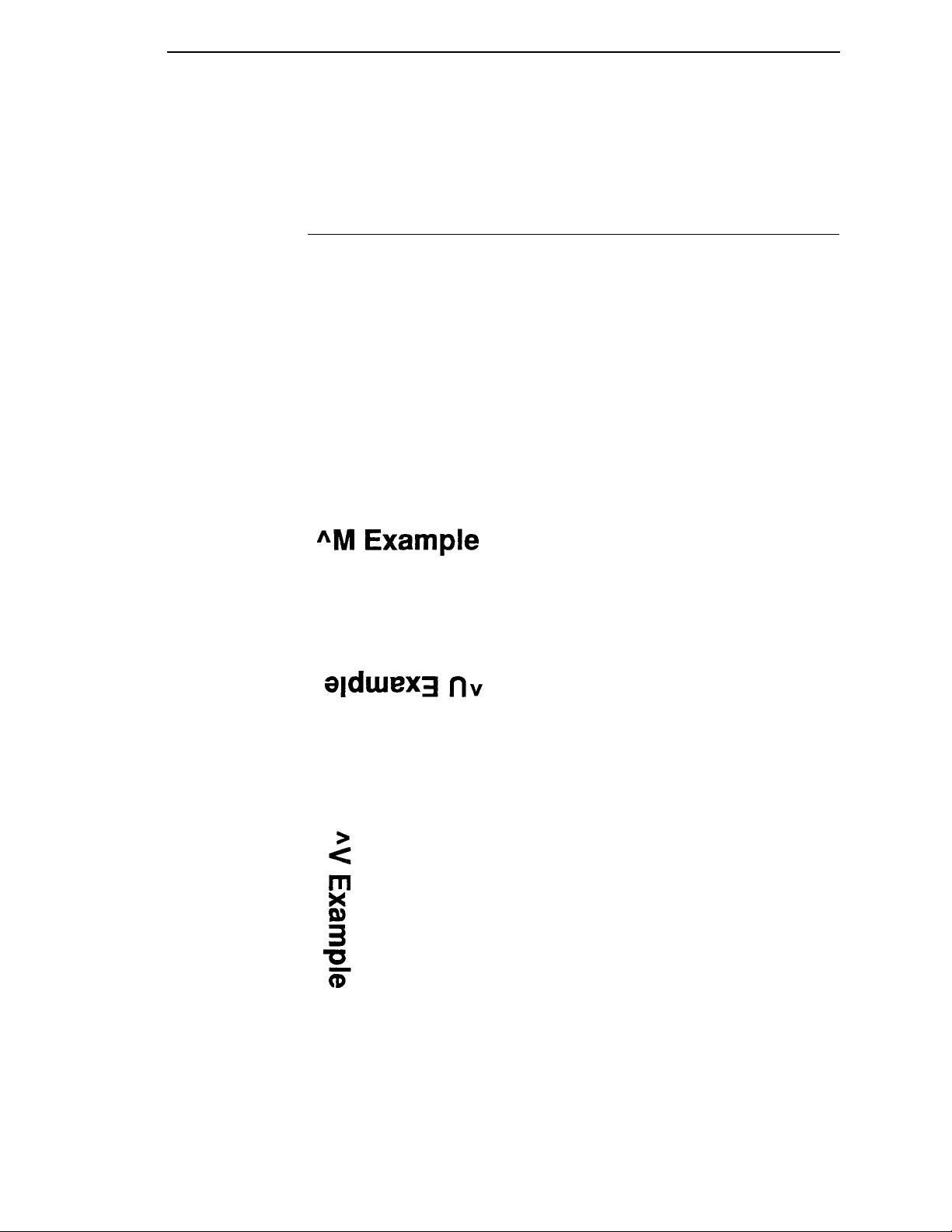
Horizontal Orientation (^M)
Prints data across the page right side up.
Upside Down Orientation (^U)
Prints data across the page upside down.
Vertical Right Orientation (^V)
Prints data down the page and roated 90 degrees clockwise so that the
baseline faces the left margin of the paper.
23
Page 24
Chapter 1 Graphics Pass
Vertical Left Orientation (^E)
Prints data down the page and roated 90 degrees counterclockwise so that
the baseline faces the right margin of the paper:
hh The height of each individual barcode or block character. This
dimension is measured vertically on the page and is specified in
increments of 0.1 inches (0.25 cm). The allowable height for each
barcode/block character ranges from 01 to 99 (0.1 to 9.9 inches
or 0.3 to 25.2 cm). For example, a value of 03 means a height of
0.3 inches (0.76 cm).
ww The width of each printed barcode/block character. This
dimension is measured horizontally on the page and is specified
in increments of 0.1 inches (0.25cm). The width for each barcode/
block character ranges from 01 to 99 (0.1 to 9.9 inches or 0.3 to
25.2 cm) For example, a value of 10 means a width of 1.0 inches
(2.5 cm).
jjd Data can be positioned down the page from the beginning of the
Pass. This is teemed justification. the jj is the amount of
justification from 00 to 99 increments of 0.1 inches (0.3 to 25.2
cm). The d allows an additional amount of justification down from
0 to 9 dot rows to fine tune the final position of the data. For
example, inserting the value 118 means the data is moved down
1.1 inches (2.8 cm) plus an additional 8 dot rows. A justification
value of 000 sets the current print position to the top of the
current Graphics Pass.
NOTE: Any values not specified will default to 0.
<data> The actual data can be printed. Characters in the data string will
be printed as block characters or in a particular GPL font.
Barcodes, lines, boxes, and formatting commands may also be
placed in the pass. The data contained within the pass is printed
in accordance with the orientation, height, width, and justifcation
values of the Graphics Pass.
^- Every Graphics Pass is terminated with a Pass Terminator,
indicating the end of the Graphics Pass. When the printer is in
Free Format Mode, the printer will only recognize ^-, ^*, and ^, as
Pass Terminators. When the pritner is not in Free Format Mode,
Carriage Return (CR), Line Feed (LF), and Form Feed (FF) may
be used. Throughout the manual, ^- will typically be used to
indicate a Terminator.
24
Page 25

GPL Commands
Most of the examples shown in this manual assume Graphics Mode and Free
Format Mode are turned on, although the examples will not always show the
^PY and ^F commands. The complete set of commands to turn Graphics and
Free Format Mode On, send GPL commands and data, then turn Free Format
and Graphics Mode Off are shown below:
^PY^- Turns on Graphics Mode
^F^- Turns on Free Format Mode
<data>^ Sample GPL Command sequences
^O^ Turns off Free Format Mode
^PN^- Turns off Graphics Mode
The above lines are typically entered into a file and sent to the printer, or are
written to the printer using a computer language such as BASIC or C with
Free Format and Graphics mode on.
The main reasons to turn Graphics mode off are:
Multiple Passes
• To print a large amount of non-GPL data.
• To reset the Code V to its default startup state.
• To send plot data to the underlying emulation.
The reamining chapters in this manual discusses how the GPL command
sequences should be formatted. For all subsequent examples in this manual,
the following conditions are assumed:
• The control panel displays ONLINE GRAPHICS.
• Graphics Mode is ON (^PY^-).
• The printer is in Free Format mode (^F^-).
Multiple Passes
A Graphics Pass may contain other GPL commands, including other ^M, ^U,
^V, and ^E commands. The printer does not begin printing a Graphics pass
until the Pass is terminated. After a pass is printed, the next pass begins at
the bottom of the printed Pass.
For example, the sequence of GPL commands
^M0101000A^M0101000B^M0101000C^- produces the same printed result
as ^M0101000ABC^- which prints:
whereas the three graphics Passes ^M0101000A^-^M0101000B^^M0101000C^- print:
25
Page 26

Chapter 1 GPL Commands
26
Page 27
2 Character Printing
Control Panel Option
A new option has been added to the control panel under the Graphics
category. The new option, Vscale, determines whether or not vertical block
characters will be scaled to match the difference between the horizontal and
vertical print densities. The option is necessary to be fully compatible with old
QMS Code V version 1 boards that are still in the field.
Block characters are build to be printed horizontally at 60 x 72. When the
characters are rotated and printed vertically, it is necessary to scale the
characters to maintain the cell size of the character. Some QMS Code V
version 1 boards do not handle this scaling, so that when a 5 x 7 block
character is rotated and printed vertically, it will actually be 4 x 8. when the
Vscale option is turned off, we will now emulate this.
Block Character
Block characters are printed by putting the characters to be printed into the
<data> portion of a Graphics Pass. Thus, the Block Character Command is
the same as the Graphics Pass Command.
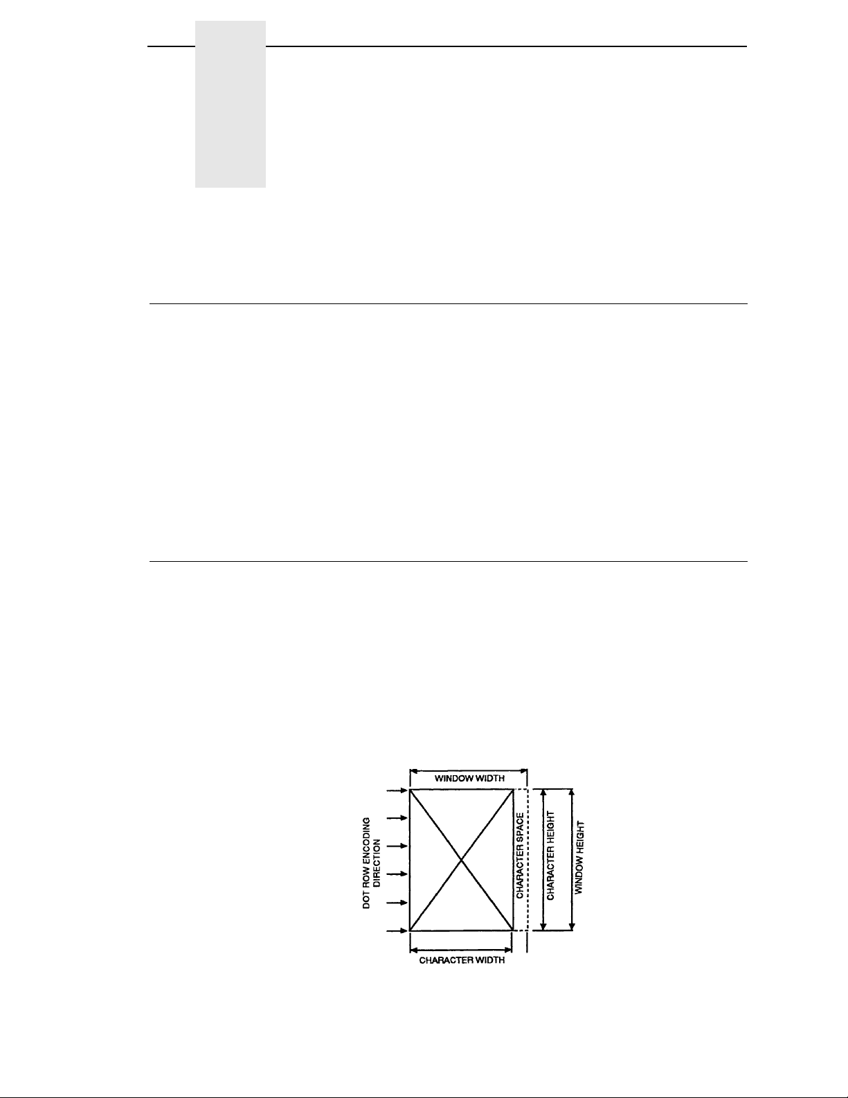
Each block character is printed within a window which includes an appropriate
amount of space for character separation. The block character window size
ranges from 0.1 inches (0.25 cm) to 9.9 inches (25.15cm) in increments of 0.1
inch (0.25 cm). the character window includes 1 dot row or column of
intercharacter space for every 0.1 inches in window size. That is, if the
Graphics Pass command is ^M0505000, then the character window size will
be 0.5 x 0.5 inches, including a 5 dot-column space to the right of the
character (see
Figure 1 on page 27).
Figure 1. Character Window
27
Page 28

Chapter 2 Block Character
When a block character is rotated 90 degrees clockwise or counterclockwise
on a page, the height and width values are exchanged:
• the Graphics Pass height value determines the new character width.
• the Graphics Pass width value determines the new character height.
Command ^{M, U, V, or E}hhwwjjd<data>^-
Arguments ^{M, U, V, or E} One of the four orientation commands ^M, ^U,
^V, or ^E.
hh The height of each printed character window. This
ww The width of each printed character window. This
jjd The vertical justification, jj, ranges from 00 to 99
dimension is measured vertically on the page and
is specified in increments of 0.1 inches (0.25 cm).
The height for each character window ranges from
01 to 99 (0.1 to 9.9 inches or 0.25 to 25.3 cm). For
example, a height of 03 means a character window
height of 0.3 inches (0.76cm).
dimension is measured horizontally on the page
and is specified in increments of 0.1 inches. The
width for each character window ranges from 01 to
99 (0.1 to 9.9 inches or 0.3 to 25.3 cm). For
example, a width of 10 means a character window
width of 1 inch (2.5 cm).
(0.0 to 9.9 inches/0.0 to 25.2 cm). The d allows an
additional amount of justification down from 0 to 9
dot rows to fine tune the final positioning. For
example, inserting the value 118 means the
characters are moved down the page 1.1 inches
(2.8 cm) plus an additional 8 dot rows. If any of the
jjd is not sent, the printer assumes the missing
values are 0. If any of the jjd is nto sent, the printer
assumes the missing values are 0. For instance,
M1010 would have a jjd value of 000.
28
<data> The actual characters to be printed. This data will
print in accordance with orientation, height, width,
and justification values.
^- The Pass Terminator
Page 29
The following examples illustrate block character printing.
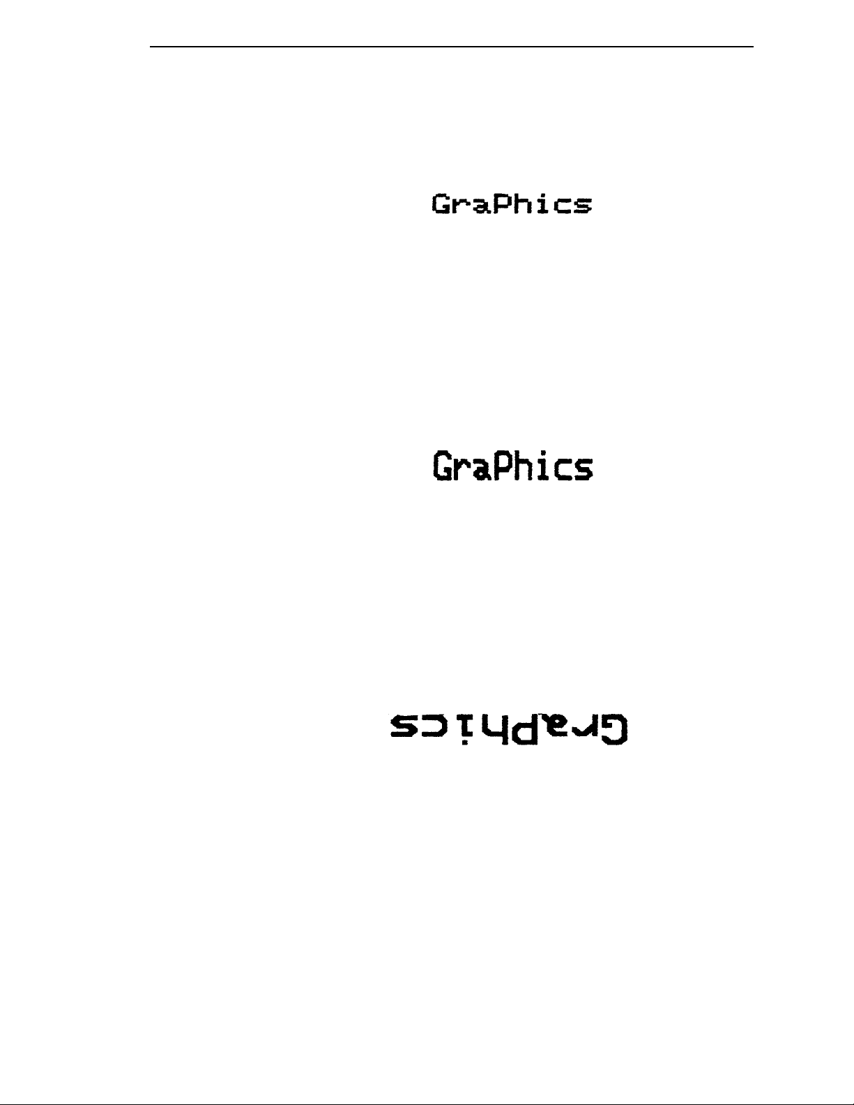
Example 1: The Graphics Pass ^M0202000Graphics ^- prints:
^M Horizontal orientation of character.
02 Character height of 0.2 inches (0.51 cm).
02 Character width of 0.2 inches (0.51 cm).
00 Justified downward 0.00 inches.
0 No additional dot rows of justification down.
Graphics Data to be printed.
^- Pass Terminator.
Example 2: The Graphics Pass ^M0302000Graphics^- prints:
^M Indicates this Graphic Pass is oriented horizontally.
03 Character height of 0.3 inches (0.76 cm).
02 Character width of 0.2 inches (0.51 cm).
00 No justification down.
0 No additional dot rows of justification down.
Graphics Data to be printed 0.3 inches high and 0.2 inches
wide.
Example 3: The Graphics Pass ^U0303000Graphics^- prints:
^U Rotated 180 degrees from the horizontal
orientation.
03 Character height of 0.3 inches (0.76 cm).
03 Character width of 0.3 inches (0.76 cm).
00 No justification down.
Graphics Block characters to be printed in the upside down
orientation.
29
Page 30
Chapter 2 Block Character
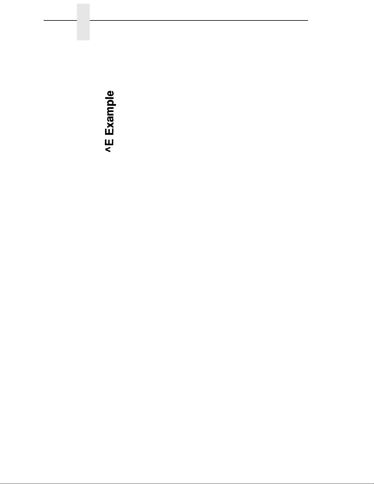
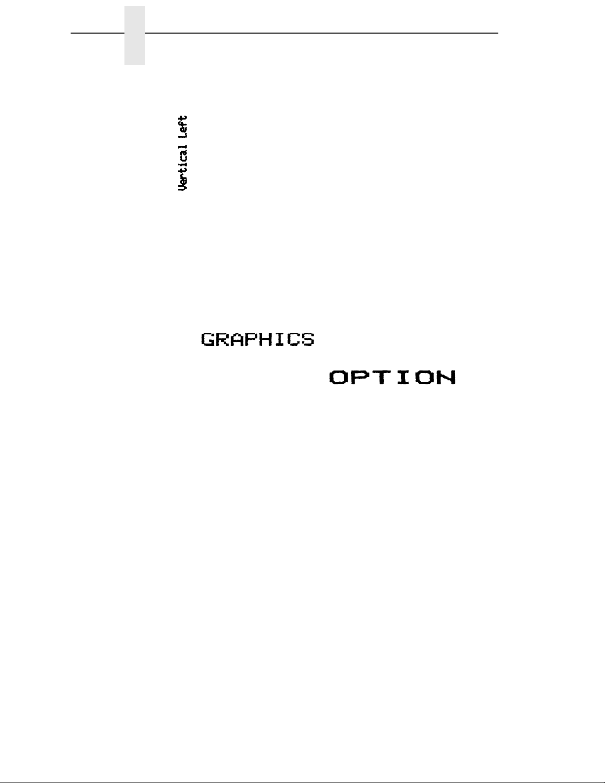
Example 4: The Graphics Pass ^E0101000Vertical Left^_ prints:
^E Vertical left orientation of the pass.
01 Character height of 0.1 inches (0.25 cm).
01 Character width of 0.1 inches (0.25 cm).
00 No justification down.
0 No additional dot rows of justification down.
Example 5: The Graphics Pass ^M0202000GRAPHICS
^M0203053OPTION^- prints:
• First Command - ^M0202000GRAPHICS
^M Horizontal orientation of the Graphics Pass.
02 Character height of 0.2 inches (0.51 cm).
02 Character width of 0.2 inches (0.51 cm).
000 No vertical justification.
GRAPHICS Data printed at 0.2 inches high and 0.2 inches
wide.
• Second Command - ^M0203053OPTION^-
^M Horizontal orientation of the Graphics Pass.
02 Character height of 0.2 inches (0.51 cm).
03 Character width of 0.3 inches (0.76 cm).
05 Justification down of 0.5 inches (1.27 cm).
3 An additional three dot rows of justification down.
OPTION Data printed at 0.2 inches high and 0.3 inches wide
with downward justification of 0.5 inches plus three
dot rows.
30
Page 31

Example 6: To place OPTION directly under GRAPHICS, a pass terminator
(^-^*) must be placed after the end of the first pass but before the
beginning of the second pass:
^M0404000GRAPHICS^-^*M0404053OPTION^- will now print:
Example 7: This example shows horizontal block characters with varying
degrees of justification.
The Graphics Pass: ^M0303060P^M0303040a^M0303020s^M0303000s^prints:
• First Command - ^M0303060
^M Horizontal orientation of characters.
03 Character height of 0.3 inches (0.76 cm).
03 Character width of 0.3 inches (0.76 cm).
06 Justified down 0.6 inches (1.5 cm).
0 No additional dot rows of justification.
P Data to be printed.
• Second Command - ^M0303040a
^M Horizontal orientation of characters.
03 Character height of 0.3 inches (0.76 cm).
03 Character width of 0.3 inches (0.76 cm).
04 Justified down 0.4 inches (1.0 cm).
0 No additional dot rows of justification.
31
Page 32

Chapter 2 Descender Mode
• Third Command - ^M0303020s
^M Horizontal orientation of characters.
03 Character height of 0.3 inches (0.76 cm).
03 Character width of 0.3 inches (0.76 cm).
02 Justified down 0.2 inches (0.51 cm).
0 No additional dot rows of justification
s Data to be printed.
• Fourth Command - ^M0303000s^-
^M Horizontal orientation of characters.
03 Character height of 0.3 inches (0.76 cm).
03 Character width of 0.3 inches (0.76 cm).
00 No justification down.
0 No additional dot rows of justification
s Data to be printed.
Descender Mode
The Descender Mode is recognized only within a Graphics Pass (^M, ^V, ^E,
or ^U has been previously sent). It can be toggled on and off as often as
desired within a Graphics Pass, and it is terminated when the Graphics Pass
terminates. The amount of space reserved for descenders is defined as two
dot rows for each 0.1 inches (0.25 cm) of character height. There are two
different formats for the Descender Mode. These can be toggled from the
control panel via the Descender option in the Graphics Category menu to
either Fixed or Auto.
If set to Fixed the descender gap is always present whenever theDescender
Mode is turned on, even if no descenders are printed.
If set to Auto, the descender gap appears only when descenders are printed.
if no descenders are printed, the gap is closed.
When Descender Mode is toggled off, all lower-case characters with
descenders are moved up so that the bottom of each descender rests on the
baseline. Lower-case characters without descenders appear the same
whether Descender Mode is ON or OFF.
NOTE: All Graphics Passes start in the default Non-Descender Mode.
Command ^D
Example 1: ^M0202000j^Dj^Dy^Dy^- prints:
32
Page 33

Reverse Image
Reverse Image causes the printer to print white block characters on a black
background. The black background extends beyond each character one dot
row or column for every 0.1 inch increment of character window size. For
example, a Reverse Image character window with a horizontal dimension of
03 (0.3 inches or 0.76 cm) and a vertical dimension of 04 (0.4 inches or 1.0
cm) will have the dark background extend three dot columns left and right of
the character(s) and four dot rows on the top and bottom.
The Reverse Image Command is valid only if it is within a Graphics Pass. If it
is outside of a Graphics Pass, it is interpreted as a Repeat Command. If the
Graphics Pass is terminated while Reverse Image is ON, Reverse Image is
automatically terminated.
Command ^R<data>^R
Arguments
Revese Image Descender Mode
^R Turns ON Reverse Image.
<data> Data to be printed in Reverse Image.
^R Turns OFF Reverse Image.
Example 1: Sending ^M0202000^RGRAPHICS^- prints:
Example 2: Sending ^M0202000^ROPT^RION^- prints:
NOTE: The reverse image characters are a few dots lower.
Revese Image Descender Mode
If Descender Mode (^D) is turned on with Reverse Image on, the entire dark
background extends down to encompass the descenders.
Example 1: Sending the Graphics Pass ^M0303000^Rfghij^R^- with
Descender Mode OFF prints:
33
Page 34

Chapter 2 Half-Tone
Example 2: Sending the Graphics Pass ^M0303000^R^Dfghij^R^D^- with
NOTE: The dark background of Reverse Image extends three dot rows
Half-Tone
Lines, boxes, and characters are printed in solid black, but they can also be
printed in patterns of dots. These patterns are called half-tones. Many half
tone patterns are available, such as vertical, horizontal, and diagonal lines, as
well as many other designs.
The selected pattern becomes the default pattern as long as the Graphics
Mode is enabled. Once Graphics Mode is disabled using the command ^PN^, the dot pattern defaults to the pattern corresponding to 04 hex.
Descender Mode ON prints:
below the descenders.
See Appendix D, “Patterns” on page 273 for all available half-tone patterns.
The following command is used to turn on the Half-Tone Mode as well as to
select a half-tone pattern:
Command ^KLxx<data>
Arguments
^KL Turns ON the Hfl-Tone Mode.
xx Specifies the half-tone pattern, where xx equals
any hex number between 00 and FF.
<data> Data to be printed using the selected pattern.
Example: The Graphics Pass ^M0303000^KL02DOT PATTERN^- prints:
^KL Turns ON the Half-Tone Mode.
02 Selects the half-tone pattern corresponding to 02.
DOT PATTERN
Data to be printed using the selected pattern.
34
Page 35

Half-Tone Toggle
Half-Tone Toggle
Once a half-tone pattern has been selected, it can be toggled ON and OFF
within a Graphics Pass with the command:
Command ^KH<data>^KH
Example: The Graphics Pass ^M0303000GRA ^KL05PHI^KHSC
OP^KHTIO^KHN^- prints:
GRA Data printed as solid black.
^KL Turns Half-Tone Mode ON.
05 Selects the 05 half-tone pattern.
PHI Data printed using selected pattern.
^KH Turns Half-Tone Mode OFF.
CS OP Data printed as solid black.
^KH Toggles Half-Tone Mode ON (half-tone pattern 05).
TIO Data printed using the selected pattern.
^KH Toggles Half-Tone Mode OFF.
N Data prints as solid black.
Half-Tone Reverse Image
The dark background in Reverse Image mode can also be printed using halftone pattern.
Example: The Graphics Pass ^M0505000^R^KL09PATTERN^KH^- prints:
^R Turns ON the Reverse Image Mode.
^KL Turns ON the Half-Tone Mode.
09 Selects the 09 dot pattern.
PATTERN The characters to be printed in Reverse Image
using the Half-Tone Mode.
^KH Turns OFF the Half-Tone Mode.
35
Page 36

Chapter 2 Half-Dot Mode (Double Density)
Half-Dot Mode (Double Density)
The Half-Dot Mode causes the printer to print at 120 DPI horizontally (the
standard print density is 60 DPI). Printing at 120 dpi results in darker printing
and reduces the stairstep effect of diagonal lines. It is most often used to
improve barcode readability. The Half-Do Mode can be toggled ON and OFF
within a Graphics Pass using the command:
Command ^KF<data>^KF
Arguments
^KF Toggles Half-Dot Mode ON.
<data> Data to be printed in Half-Dot Mode.
^KF Toggles Half-Dot Mode OFF.
Example: Half-Dot characters can be mixed with regular characters. The
Graphics Pass ^M0303000^KFHALF-^KFDOT MODE^- prints:
^KF Turns ON Half-Dot Mode.
HALF Data to be printed in Half-Dot Mode.
^KF Turns OFF Half-Dot Mode.
DOT MODE Data to be printed in regular density.
Half-Dot Mode And Half-Tones
Half-Dot mode (Double Density) can be intermixed with half-tones to produce
a greater variety of shades.
Example: The Graphics Passes ^M0303000^KLEAGRAPHIC^KH^
^M0303040^KH^KFOPTION^KF^KH^- prints:
• First Graphic Pass - ^M0303000^KLEAGRAPHIC^KH^
^KL Turns ON Half-Tone Mode.
EA Selects EA half-tone pattern.
36
GRAPHIC Data printed in the selected pattern.
^KH Turns OFF Half-Tone Mode.
Page 37

• Second Graphics Pass - ^M0303040^KH^KFOPTION^KF^KH^-
^KH Toggles Half-Tone Mode ON and defaults to last
^KF Toggles ON Half-Dot Mode.
OPTION Data printed with the selected pattern (EA) in Half-
^KF Toggles OFF Half-Dot Mode.
^KH Toggles OFF Half-Tone Mode.
Block Character Fonts
Block character fonts are created from the block character set in four graphic
orientations, and are available in the following sizes:
• 7.5 CPI block characters, 0.2 inches high.
• 10 CPI block characters, 0.1 inch high.
7.5 CPI
pattern selected (EA).
Tone/Half-Dot Mode.
• 12 CPI block characters, 0.1 inch high.
• 15 CPI block characters, 0.1 inch high.
7.5 CPI
The 7.5 CPI character set is 2/10 inches high and 0.15 inches wide (0.51 cm
high by 0.38 cm wide). All characters in this set are printed in upper case,
even if the characters received from the host are lower case.
Command ^{M,U,V,E}0000jjD<data>^-
Arguments
^{M,U,V,E} One of four Graphics Pass orientations (^M for
horizontal, ^V for clockwise rotation, ^E for
counterclockwise rotation, or ^U for upside down
and reverse order of characters.)
0000 A height/width value of 0000 specifies 7.5 cpi
characters.
jjd Justification values in increments of 0.1 inches
(0.25 cm) and dot rows as discussed in the
Graphics Pass Command description below. This
field may be omitted entirely if the justification value
is zero.
<data> The characters to be printed.
Example: The Graphics Pass ^M00000007.5 CPI CHARACTERS^- prints:
37
Page 38

Chapter 2 Block Character Fonts
10 CPI
The 10 CPI block character set is 0.1 inches high and is selected by using the
following Graphics Pass Command.
Command ^{M,U,V,E}0101jjd<data>^-
Arguments
^{M,U,V,E} One of four Graphics Pass orientations (^M for
0101 A height/width value of 0101 specifies 10 CPI
jjd Justification values in increments of 0.1 inches
horizontal, ^V for clockwise rotation, ^E for
counterclockwise rotation, or ^U for upside down
and reverse order of characters).
characters.
(0.25 cm) and dot rows as discussed in the
Graphics Pass Command description below. This
field may be omitted entirely if the justification value
is zero.
<data> The characters to be printed.
Example 1: The Graphics Pass ^M0101000HORIZONTAL 10 CPI^- prints:
Example 2: ^M0101000HORIZONTAL 10 CPI
^M0202000HORIZONTAL 5 CPI^- prints:
38
Page 39

12 CPI
12 CPI
The 12 CPI character set is 0.1 inches high and is selected with the following
special Graphics Pass command.
Command ^{M,U,V,E}0001jjD<data>-
Arguments
^{M,U,V,E} One of four Graphics Pass orientations (^M for
horizontal, ^V for clockwise rotation, ^E for
counterclockwise rotation, or ^U for upside down
and reverse order of characters).
0001 A height/width value of 0001 specifies 12 cpi
characters.
jjd Justification values in increments of 0.1 inches
(0.25 cm) and dot rows, as in the Graphics Pass
command description. This field may be omitted
entirely if the justification value is zero.
<data> The characters to be printed.
Example: The Graphics pass ^M000100012 CPI CHARACTERS^- prints:
15 CPI
The 15 CPI character set is 0.1 inches high and is selected using the following
command.
Command ^{M,U,V,E}0100jjD<data>^-
Arguments
^{M,U,V,E} One of four Graphics Pass orientations (^M for
horizontal, ^V for clockwise rotation, ^E for
counterclockwise rotation, or ^U for upside down
and reverse order of characters).
0100 A height/width value of 0100 specifies 15 cpi
characters.
jjd Justification values in increments of 0.1 inches
(0.25 cm) and dot rows, as in the Graphics Pass
command description. This field may be omitted
entirely if the justification value is zero.
<data> The characters to be printed.
Example: The Graphics Pass ^M010000015 CPI CHARACTERS^- prints:
39
Page 40

Chapter 2 Code V Font Selection
Code V Font Selection
Since Code V runs on top of another emulation, the Code V Language has
the ability to print either emulation fonts or Code V fonts. When Code V is
turned on via the ^PY^- command, it sets the out of pass font to the 10 CPI
Draft emulation font using the character set selected on the Control Panel.
Code V has the ability to select different kinds of fonts via Code V font
commands. These font commands and their effect(s) are listed below:
^IFONT,S# If issued inside a pass, the specified font is changed for the
duration of the pass. If issued outside a pass, the font is changed
to the specified Code V font both inside and outside passes.
^S# Valid only inside a pass, this command changes the font of the
characters in the current pass to the specified Code V font.
^# Valid only outside a pass, this command changes the font of the
characters outside passes to the specified Code V font.
^@C Valid only outside a pass, this command changes the emulation
font, thus affecting Code V outisde of pass characters and
characters printed after exiting Code V.
Code V Character Set Selection
All emulations and Code V have two character sets: upper (eigth bit high) and
lower (eigth bit low). For all Code V fonts, the default lower character set
(characters 20 - 7F hex) is US and the default upper character set (characters
A0 - FF hex) is Latin1. Complete charts for the US and Latin1 character sets
are available in Appendix F,
The CVCC font lower character set may be selected within Code V by using
the ^IISO command. The Code V font upper character set cannot be changed
and is always Latin1. Changing the character set via the control panel does
not alter the Code V character sets. The effects of the ^IISO command are
described below.
• When ^IISO is sent inside a pass:
The selected ISO character set (also called language in the Code V
manual) lasts only until the end of that pass.
• When ^IISO is sent outside a pass:
The selected ISO character set is used both inside and outside passes
until Code V is exited. Also, upon re-entering Code V, the ISO character
set selection made during the previous Code V session is retained.
To form an ISO character set, ^IIISO only changes 12 characters from the
lower US set. These 12 character differences are shown for each ISO
character set on
page 47.
Table 46: on page 287.
40
Page 41

The upper Code V character set contains the following characters not found in
the Latin1 set:
Compressed Fonts
Code V has the following nine compressed fonts for use in normal printing
outside of a Graphics Pass.
15 CPI
• Near Letter Quality (NLQ) character sets at 10, 12, 13.3, 15, and 17.1
CPI.
• OCR-A and OCR-B 0.10 inch character sets at 10 CPI.
Emulation control codes are supported with Compressed Fonts Mode; escape
sequences are not. To print characters within a Graphics Pass, see
Pass” on page 21.
Command ^#n^-
Arguments
^# Turns ON the Compressed Font Mode
n Font selection.
1 for NLQ (10 CPI)
2 for NLQ (12 CPI)
3 for NLQ (13.3 CPI)
4 for NLQ (15 CPI)
5 for NLQ (17.1 CPI)
6 for OCR-A (10 CPI)
7 for OCR-B (10 CPI)
8 for Draft (12 CPI)
9 for Draft (15 CPI)
To turn off the Compressed Fonts Mode, send the command ^#0^-
“Graphics
41
Page 42

Chapter 2 NLQ Fonts
Example 1: The command ^#6OCR-A characters^- prints:
Example 2: The commands ^M0202000GRAPHICS PASS^-^*^#2^-
NLQ Fonts
The NLQ fonts use 0.10 inch high Gothic characters whenever high quality
print or high density is desired. NLQ fonts are limited to Horizontal Orientation
only, and the NLQ Font command must be contained within a Graphics Pass.
If the NLQ Font command is outside of a Graphics pass, it is interpreted as a
Horizontal Repeat command (see Repeating Text later in this manual). The
NLQ font is in effect only until the next command is received.
COMPRESSED FONT^- prints:
Any horizontal tabs and justification functions (see “Positioning and
Repeating” on page 83) used with NLQ characters should be used prior to the
^Sn command. If a Tab or Justification Command is encountered within the
NLQ characters, the selected NLQ Graphics font is terminated and a Block
Character font is substituted for the remaining printable data.
To select one of the NLQ Graphics fonts, send the following command.
Command ^Sn
Arguments
^Sn The NLQ Font Command.
nNLQ Font
1 for 10 CPI
2 for 12 CPI
3 for 13.3 CPI
4 for 15 CPI
5 for 17.1 CPI
6 for OCR-A (10 CPI)
7 for OCR-B (10 CPI)
Example 1: The Graphics Pass ^M0000000^S1A line of text^- (1/10th inch
NLQ characters at 10 CPI) prints:
42
Page 43

Example 2: The Graphics Pass ^M0000000^S1A line^T0100of text^- (10 CPI)
prints:
Default Font Selection
This command allows selection of a default font that when issued inside a
pass, selects the font used for the duration of that pass only. When used
outside a pass, it selects the font used in all non-graphics printing.
Command ^IFONTS,S,n^G<data>
Arguments
^IFONTS,S, Indicates that a new font style will be selected.
n The number of the selected default font. This
15 CPI
parameter can have up to five digits, although only
the following values are used:
1 = Draft at 10 CPI
2 = Draft at 12 CPI
3 = Draft at 15 CPI
4 = Draft at 7.5 CPI
5 = NLQ at 10 CPI
6 = NLQ at 12 CPI
7 = NLQ at 13.3 CPI
8 = NLQ at 15 CPI
9 = NLQ at 17.1 CPI
10 = OCR-A (10 CPI)
11 = OCR-B (10 CPI)
12 = Symbol Set Low Density
13 = Symbol Set High Density
^G Command Terminator
<data> The data to be printed using the new font style.
Example: The human-readable characters can be printed in the OCR-A font
style by sending the command
^M0202000^IFONTS,S,10^G12345^-, which prints:
^M0202000
Sets up Horizontal orientation and the window size
for the non-translated data characters at 0.2 inches
(0.51 cm) square with no justification.
^IFONT,S, Indicates that a new font style will be selected.
10 Selects OCR-A at 10 CPI.
^G Command Terminator.
12345 Data to be printed using OCR-A at 10 CPI.
43
Page 44

Chapter 2 Draft Fonts
Draft Fonts
The draft fonts, when issued inside a pass, select the font used for the
duration of that pass only. When used outside a pass, they select the font
used in all non-graphics printing.
Command ^@Cnn
Arguments
^@C Draft Font Command.
nn One of the draft font numbers listed below:
05 = double high (0.2 inch), 7.5 CPI.
10 = 10 CPI
12 = 12 CPI
13 = 13.3 CPI
15 = 15 CPI
17 = 17.1 CPI
Font/Quality Speed
Code V is capable of printing most of the Code V fonts at three different
speeds and qualities. The slowest print speed produces the highest quality
fonts, while the fastest print speed produces the lowest quality fonts. A Font
Quality/Speed Command may be sent either inside or outside of a pass and
remains in effect until another Font Quality/Speed Command is issued or
Graphics Mode is exited.
These commands only affect the Code V Draft Font at 12, 13.3, 15, and 17.1
CPI and the Code V NLQ Font at 10, 12, 13.3, and 17.1 CPI.
The three Code V Font Quality/Speed commands are: High-Quality Font, FullSpace Font, and Half-Space Font.
High Quality Font Mode
Selects slow-speed, high quality fonts. The DPI of the font selected by a Code
V Font Command depends upon the selected font and may cause the paper
to back up and the shuttle to change speed. Fonts printed in this mode are
positioned on character cell boundaries.
Command ^~FQ
Full Space Font Mode
44
Selects 120 DPI, medium speed, medium quality fonts. The paper will not
back up to print any Code V font (excluding OCR) when ^~FF is selected.
This is the default.
Command ^~FF
Page 45

Half Space Font Mode
Selects 60 DPI, fast speed, lowest quality fonts. The paper will not back up to
print any GPL font (excluding OCR) when ^~FH is selected.
Command ^~FH
Lines Per Inch
The number of character lines per inch may be set with the command:
Command ^@Lnn
Arguments
Half Space Font Mode
^@L The Lines Per Inch Command.
nn One of the lines per inch numbers below:
03 = 3 LPI
04 = 4 LPI
06 = 6 LPI
08 = 8 LPI
Dump Mode
The data received from the host may be printed in hexadecimal Dump Mode
format using the Dump Mode command. Dump Mode is typically used to
examine the data received from the host.
NOTE: Dump Modes are explained on page 45.
Command ^@Hn
Arguments
Hex Command
The Hex Command allows the user to send single hexadecimal values to the
printer. This is useful when you want to send a control code.
Command ^IHEX,xx
Arguments
^@H The Dump Mode Command
n Mode selection
0 or 1 selects Control Panel Dump Mode style 1.
2 selects Control Panel Dump Mode style 2.
3 selects Control Panel Dump Mode style 3.
^IHEX, The Hex Command
xx The hexadecimal value to send to the printer
(00 - FF).
45
Page 46

Chapter 2 Control Panel Option
Control Panel Option
The following Control Panel option provides more control of speed and
quality.
Block Character
This option allows you to set the size at which Block Character Smoothing
begins.
NOTE: Smoothing slows down the Code V processing. The default is size 3.
ISO Character Sets
Several international standard character sets may be selected with this
command. When issued inside a pass, this command selects the ISO
language for the duration of that pass only. When issued outside a pass, it
selects the language used in all non-pass printing.
There are 12 character positions which differ depending on the ISO language
selected. See below.
NOTE: The ISO characters can only be used inside of a Graphics Pass when
using the Twinax or Coax interface.
Command ^IISO,n^G
Arguments
^IISO, Command Identifier, selects an ISO character set.
n^ The number of the desired character set.
^G Command Terminator
46
Page 47

ISO Character Set Table
Block Character
47
Page 48

Chapter 2 ISO Character Set Table
48
Page 49

3 Creating Lines And
Line Drawing
Code V allows printing of solid or dashed lines of various thicknesses and
orientations. The following sections describe the line drawing commands and
their usage.
Solid Lines
Description Solid lines can be printed horizontally and vertically ranging in
Command ^LShhhdvvvd
Graphics
width and length from one dot to 13.2 inches. The solid line
command is:
Arguments
^LS Solid Line command
hhh The horizontal dimensions, specified in increments of 0.1 inches
(0.25 cm), ranging from 000 to 132 (0 to 13.2 inches or 0 to
33.6 cm).
d Additional dot columns, ranging from 0 to 9 dot-columns.
vvv The vertical dimensions, specified in increments of 0.1 inches
(0.25 cm), ranging from 000 to 132 (0 to 13.2 inches or 0 to 33.6
cm).
d Additional dot columns, ranging from 0 to 9 dot-columns.
NOTE: The length and thickness of a line must be at least one dot.
49
Page 50

Chapter 3 Line Drawing
Example 1: The command ^LS04000001^- prints a horizontal line exactly
Example 2: The command ^LS0500011^- prints a horizontal line 3.5 inches
4 inches (10.2 cm) long and 1 dot row thick.
^LS Solid line print command.
040 A horizontal dimension of 4.0 inches (10.2 cm).
0 No dot column additions to the horizontal
dimensions.
000 No vertical dimensions in increments of 0.1 inch
(0.25 cm).
1 Additional vertical dimensions of 1 dot row.
(8.9 cm) long and 0.1 inches (0.25 cm) plus 1 dot row thick.
^LS Solid Line Print command
035 A horizontal dimension of 3.5 inches (8.9 cm).
0 No dot column additions to the horizontal
dimensions.
001 A vertical dimension of 0.1 inches (0.25 cm).
1 Additional vertical dimensions of 1 dot row.
Example 3: The command ^LS00020110^- prints a vertical line 2 dot columns
wide and 1.1 inches (2.79 cm) high.
^LS Solid Line Print command
0002 A horizontal dimension of 2 dot columns.
0110 A vertical dimension of 1.1 inches (2.79 cm).
50
Page 51

Dashed Lines
Dashed Lines
Description Dashed lines are drawn by printing alternate tenths of an inch
(every 0.25 cm). The individual dashed marks will be oriented to
the line’s strongest dimension (horizontal or vertical). If the
horizontal and vertical lengths are equal, the dashes will be
horizontal. Dashed lines can be printed using the command:
Command ^LDhhhdvvvd
Arguments
^LD Dashed Line command
hhh The horizontal dimension, specified in increments of 0.1 inches
(0.25 cm), ranging from 000 to 132 (0 to 13.2 inches or 0 to
33.6 cm).
d Additional dot columns, from 0 to 9.
vvv - The vertical dimension, specified in increments of 0.1 inches
(0.25 cm), ranging from 000 to 132 (0 to 13.2 inches or 0 to 33.6
cm).
d - Additional dot rows, from 0 to 9.
Example 1: The command ^LD02000010^- prints a horizontal dashed line
exactly 2.0 inches 95.08 cm) long and 0.10 inches tall.
^LD Dashed Line command
0200 Specifies a horizontal dimension of 2.0 inches.
0010 Specifies a vertical dimension of 0.10 inch.
51
Page 52

Chapter 3 Line Drawing
Example 2: The command ^LD00100210^- prints a vertical dashed line
0.10 inch wide and 2.1 inches (5.3 cm) tall.
^LD Dashed Line command
0010 Specifies a horizontal dimension of 0.1 inches.
0210 Specifies a vertical dimension of 2.1 inches.
Example 3: Dashed lines will print horizontally if the horizontal and vertical
dimensions are the same. The command ^LD01000100 will print
a series of vertical stripes 0.1 inches (0.25 cm) wide across a
space that is 1.0 inches (2.5 cm) square.
^LD Dashed Line command
0100 Horizontal dimension of 1.0 inches.
0100 Vertical dimension of 1.0 inches.
52
Page 53

Boxes
Dashed Lines
Description Boxes can be drawn in a variety of shapes, sizes, and line
weights. Maximum box size is limited to the maximum printed
pass length and the width of the paper being printed upon.
NOTE: When printing boxes, the minimum box length must be greater than
twice the thickness of the vertical borders.
The minimum box height must be greater than twice the thickness of
the horizontal borders.
The command for drawing a box is:
Command ^LBhhhdvvvdhv
Arguments
^LB The Box command.
hhh Horizontal length of the box in increments of 0.1 inches (0.25 cm)
from 001 to 132 (0.1 to 13.2 inches or 0.25 to 33.53 cm).
d Additional horizontal length of the box in dot-columns, ranging
from 0 to 9.
vvv Vertical height of the box in increments of 0.1 inches (0.25 cm).
d Additional vertical height of the box in dot columns, ranging from
0 to 9.
h Thickness of the top and bottom borders of the box, ranging from
1 to 9 dot rows.
v Thickness of the two vertical borders of the box, ranging from 1 to
9 dot columns.
Example 1: The command ^LB0250010062^- prints the following box:
^LB The Box command
0250 The lengths of the top of the bottom borders are 2.5
inches (1.27 cm) with no additional dot columns.
0100 Line lengths of the left and right borders are 1 inch
each (2.54 cm) with no additional dot rows.
6 Line thickness for top and bottom borders is 6 dot
rows.
2 Line thickness for the right and left borders is 2 dot
rows.
53
Page 54

Chapter 3 Boxes
Example 2: The command ^LB0250010025^- prints the following:
^LB The Box command
0250 Line lengths for top and bottom borders of 2.5
inches (6.4 cm) with no additional dot columns.
0100 Line lengths for left and right borders of 1.0 inches
(2.54 cm) with no additional dot rows.
2 Thickness of top and bottom borders is 2 dot rows.
4 Thickness of left and right borders is 4 dot columns.
Example 3: The command ^LB0010025046^- prints the following:
^LB The Box command
0010 Line length for top and bottom borders is 0.1 inches
(0.25 cm) with no additional dot columns.
0250 Line length for right and left borders is 2.5 inches.
4 Thickness for top and bottom borders is 4 dot rows.
6 Thickness for right and left borders is 6 dot
columns.
54
Page 55

Dashed Lines
Example 4: The Graphics Pass, ^M0202000^LB00900009011GRAPHICS^-
prints the following box and characters:
^LB The Box command
0090 Horizontal length of box is 0.9 inches.
0090 Vertical height of box is 0.9 inches.
1 Thickness of top and bottom borders is 1 dot row.
1 Thickness of right and left borders is 1 dot column.
GRAPHICS Data to be printed with each character is 0.2 inches
(0.51 cm) square.
Form Drawing
Description The GPL Form command is used to draw boxes with vertical lines
Command ^LFhhhdvvvdhvllldt... ^G
Arguments
ineside. The height of the vertical lines is restricted to the vertical
dimensions of the box, and the maximum thickness of each line is
limited to nine dot columns.
The Form command has the following format:
^LF The Form command
hhh Horizontal dimensions of the box in 0.10 inch
increments from 001 to 132 (0.1 to 13.2 inches).
d Additional horizontal dimensions of the box in
dot-columns, ranging from 0 to 9.
vvv Vertical height of the box in 0.10 inch increments.
d Additional vertical height of the box in dot-columns,
ranging from 0 to 9.
h Thickness of the two horizontal borders of the box
in dot rows, ranging from 1 to 9.
v Thickness of the two vertical borders of the box in
dot columns, ranging from 1 to 9.
lll Horizontal positioning of the first vertical line from
the left margin in 0.10 inch increments from 001 to
132 (0.1 to 13.2 inches).
55
Page 56

Chapter 3 Form Drawing
Example 1: The Graphics Pass ^LF03000150110050010100101003^G prints
d Additional horizontal positioning of the first vertical
line in dot columns, ranging from 0 to 9.
t Thickness of the first vertical line in dot columns,
ranging from 1 to 9.
... Represents a repeat of the llldt command for each
additional vertical line to be printed. The distance
between each vertical line is additive, i.e., each
additional vertical line is placed relative to the
previous line, not from the left margin.
^G Command Terminator
the following box and vertical lines.
^LF The Form command
0300 Horizontal box dimension of 3.0 inches with no
additional dot columns.
0150 Vertical box dimension of 1.5 inches with no
additional dot rows.
1 Thickness of each horizontal border is 1 dot row.
1 Thickness of each vertical border is 1 dot column.
005 First vertical line is positioned 0.5 inches from left
edge of box.
0 No additional dot columns added to position of first
vertical line.
1 Thickness of the first vertical line is 1 dot column.
010 Second vertical line is positioned 1.0 inches from
the first vertical line.
0 No additional dot columns added to position of
second vertical line.
1 Thickness of second vertical line is 1 dot column.
010 Third vertical line is positioned 1.0 inches from the
second vertical line.
0 No additional dot columns added to position of third
vertical line.
56
3 Thickness of third vertical line is 3 dot columns.
^G Command Terminator
Page 57

Plot Mode
Dashed Lines
Description Plot Mode allows you to create and print your own graphics
images. The Plot Mode command must be inside a Graphics
Pass.
Plot data is based on vertical columns of seven dots each. Each
column is described by a hex byte that specifies which of the
seven dots to print. The Least Significant Bit (LSB) of the byte is
mapped to the bottom of the column, while the eighth bit is
ignored. See
Hex Value Bit Dot
Table 2.
Tabl e 2. Least Significant Bit
80 7 Not used
40 6 1 (top)
20 5 2
10 4 3
08 3 4
04 2 5
02 1 6
01 0 7 (bottom)
Command ^Q<plot data>^G
Arguments
^Q Enters Plot Mode
<plot data> The hex plot data.
^G Exits Plot Mode
Example 1: This example prints an X. The command sequence is
^M^Q41,22,14,08,14,22,41^G^-
NOTE: Commas are not required between the data and do not affect the
results. Pass terminators placed between two plot commands will
cause one extra blank dot row to be plotted between the plot images.
To eliminate the blank row, keep subsequent plot commands within
the same pass. To eliminate the blank row, keep subsequent plot
commands within the same pass. Tab and justify commands can be
used to position plot images anywhere in a pass.
57
Page 58

Chapter 3 Logos
The X is drawn dot by dot as illustrated in Figure 2.
Figure 2. Plot Mode Example
Logos
A set of predefined logos come with Code V. See Appendix C, “Logos” on
page 271 for a table of logos. The first twelve are available in all four
orientations; the last two only work in horizontal and upside down orientations.
There are two commands for printing logos: Version 1 Command and Version
2 Command. The Version 1 Command can only print the copyright and
registered trademark logos, the Version 2 Command prints all the logos.
Version 1 Logos
The Version 1 logo command can only print the horizontal registered
trademark and copyright logos. The logo command must be within a Graphics
Pass.
Command ^Zn
Arguments
^Z Version 1 logo command
n Either 1 or 2. A value of 1 prints ® and a value of 2
prints ©.
Example: The command sequence ^M0404REGISTER^Z1^- prints:
58
Page 59

Version 2 logos
Version 2 logos
The Version 2 logo command prints all logos. The logo command must occur
within a Graphics Pass.
Command ^ILOGO,d,nn^G
Arguments
^ILOGO Version 2 logo command
d Density: H=high, L=low
nn A hex number indicating the logo to be used.
See Appendix C, “Logos” on page 271 for a listing
of logo numbers.
^G Command Terminator
NOTE: If “d” is left out, density defaults are low.
Example: The command
^M0202000^ILOGO,L,43^G^U0202000^ILOGO,L,43^G
^V0202000^ILOGO,L43^G^E0202000^ILOGO,L,43^G^- prints:
Pixel Expansion
The Pixel Expansion command expands logos, fonts, and plot data up to 255
times their original size. The Pixel Expansion command remains in effect until
a new Pixel Expansion command is received. To turn Pixel Expansion on,
send the following code.
Command ^IPEXP,h,v^G
Arguments
Example 1: The code ^M0101000^ILOGO,L45^G^- prints the UL symbol in its
^IPEXP The Pixel Expansion command
h Represents the horizontal Pixel Expansion value,
which ranges from 1 to 255.
v Represents the vertical Pixel Expansion value,
which ranges from 1 to 255.
^G Command Terminator
original size.
59
Page 60

Chapter 3 Pixel Expansion
To enlarge the logo, send the Pixel Expansion code first, followed
by the logo command.
For example, ^M0101000^IPEXP,3,3^G^ILOGO,L45^G^- prints:
Example 2: Sending the code ^M^IFONT,S,3^Gline of Text^- prints at the
normal size:
Whereas sending the code ^M^IFONT,S,3^G^IPEXP,4,3^GLine
of Text^- prints:
60
Page 61

4 Barcodes
The CVCC provides the capability to print several standard barcode styles
with or without accompanying human-readable characters. All barcode
encoding algorithms reside in the printer. The user needs to only send the
Barcode Command followed by the data to encode, and the printer will do the
rest. The Barcode styles included in the CVCC are:
• Code 39
• Code 128
• Interleaved 2 of 5
• UPC A
• UPC E
• EAN
• Codabar
• Identicon 2 of 5
• MSI
• Postnet
Barcodes may be printed in all of the four standard orientations (in Version 2
only), with or without human-readable character translation in any of the
available fonts, and at any height ranging from 0.3 to 9.9 inches. In addition,
many of the above styles are available with or without check digits and all
allow adjustment of bar/space ratios.
To print a barcode, the Barcode Command followed by the data to be
encoded must be sent to the printer as part of a Graphics Pass. When the
printer receives the Barcode Command, it first verifies that the data sent
adheres to the established specifications for that barcode. If the data does not
meet the specifications, the printer will print out the Barcode Command and
data as an error message.
Some barcodes have a fixed number of digits: UPC and EAN, for instance. If
less than the fixed number of digits is specified, the printer pads to the fixed
number of digits with zeros on the left of the data. If more than the fixed
number of digits is specified, the number is truncated and the remaining digits
on the right are ignored.
61
Page 62

Chapter 4
Selecting Barcodes
Code V supports Version 1 and Version 2 Barcode commands. Version 1
commands allow more flexibility in the placement of the human-readable text
portion of a barcode. Version 2 commands have the advantage of including
the name of the barcode style in the command. Either command must be
contained within a valid Graphics Pass for it to be recognized by the printer.
The Version 1 command allows the barcodes to be printed in two orientations:
1. Horizontal
2. Vertical (rotated 90 degrees clockwise from horizontal).
The orientation of a Version 1 barcode is independent of the orientation of the
Graphics Pass it is in.
The orientation of Version 2 barcode is the same as the Graphics Pass in
which it appears. Thus, Version 2 barcodes may be printed in any of the four
Graphics orientations.
Regardless of the command style used, all Barcode commands must occur
within a Graphics Pass.
Barcode Density
A control panel option (Darkbar) defines the Barcode density. If set to ON, the
density will be high. The default setting of this option is OFF.
Barcode Height
The overall height of a barcode is determined by the window height (when the
barcode is horizontal or upside down) or width (when the barcode is vertical
right or vertical left) as specified in the ^M sequence that precedes the
Barcode Command Sequence. Human-readable characters are included in
the overall barcode height.
The height range is:
• 02 to 99 (0.2 to 9.9 inches) without human-readable characters (HRC).
• 03 to 99 (0.3 to 9.9 inches) with human-readable characters (HRC).
Character sizes less than 02 or 03 will cause the barcode height to assume
the minimum value (i.e., 0.2 inches without HRC and 0.3 inches with HRC).
Barcode Width
The width of a barcode is a function of the number of data characters to be
encoded, the style of barcode, and the bar/space ratios.
62
Page 63

Barcode Version 1
The Version 1 command for printing a barcode is:
Command Default Ratio: ^{B,C}ax<data>^G
Variable Ratio: ^{B,C}a9x<ratio><data>^G
Arguments
^{B,C} B to print a horizontal barcode, or C to print a
vertical barcode.
a One of the following characters:
B, prints the OCR-B font three dots below the
barcode.
N, turns OFF auto-printing.
O, turns ON OCR auto-printing.
S, prints OCR-A 0.10 inch below the barcode.
T, prints OCR-B 0.10 inch below the barcode.
Y, turns ON OCR-A auto-printing.
Barcode Version 1
9 Selects the variable ratio feature.
x The character from Table 3 that corresponds to the
desired barcode style.
<ratio> A sequence of bar/space ratios of the form r1r2r3r4
or r1r2r3r4r5r6r7r8, where r variables take on
values 00 through 0F, hexidecimal.
<data> The data to be encoded.
^G Command Terminator
Example 1: The Graphics Pass ^M0515000^BNA12345^G^- prints:
^M0515000 Turns ON the Graphics Pass Mode. The barcode
height is 0.5 inches and the vertical justification is 0
inches.
^B Indicates the barcode orientation will be horizontal.
N No human readable characters will be printed
below the barcode.
A The Code 39 barcode style (see Table 3).
12345 The data to be encoded as a barcode.
63
Page 64

Chapter 4
Example 2: The Graphics Pass ^M0515000^CYD67890^G^- prints:
^M0515000 Turns ON the Graphics Pass Mode. Barcode height
is 1.5 inches with no vertical justification.
^C Indicates the barcode orientation will be vertical.
Y Non-OCR human-readable characters will print.
D The Codabar barcode style (see Table 3).
67890 The data to be printed as a barcode and human-
readable characters.
Barcode Version 2
The Version 2 command for printing a barcode is:
Command Default Ratio: ^IBARC,x,a,<data>^G
Variable Ratio: ^IBARC,x,R<ratio>,a,<data>^G
Arguments
^IBARC Turns on the Barcode Mode.
x The index name of one of the barcode styles
selected from
R Specifies that a ratio specification sequence
follows.
<ratio> A sequence of bar/space ratios of the form r1r2r3r4
or r1r2r3r4r5r6r7r8, where r variables take on
values 00 through 0F, hexidecimal.
NOTE: Colons must be used for Version 2 to separate the ratio parameters.
a Controls the Autoprint feature (prints human-
readable characters in the currently selected font).
You can choose from:
N, turns off autoprinting.
E, human-readable characters are printed partially
embedded into the bottom of the barcode region.
The barcode is not printed in the embedded
portion. This method of barcode printing is usually
done only for UPC and EAN barcodes.
Table 3.
64
B, prints human-readable characters below the
barcode.
Page 65

Barcode Version 2
<data> The alphanumeric characters to be encoded.
^G Command Terminator
Ta bl e 3 shows the available barcode styles and associated indices:
Tabl e 3. Valide Barcode Symbologies
Version 1
Index
--- AIAG Code 39 None 1:1:3:3
--- EMBARC Code 39 None 1:1:3:3
--- HIBCC Code 39 Mod 43 1:1:3:3
A C39 Code 39 None 1:1:3:3
--- LOGMAR Code 39 None 1:1:3:3
B C39A Code 39 None 1:2:4:5
C C39M43 Code 39 Mod 43 1:1:3:3
D CBAR Codabar None 1:2:3:4:1:1:1:1
E --- Identicon 2/5 None 1:2:3;2
F MSI MSI None 1:1:2:2
G MSI10 MSI Mod 10 1:1:2:2
H MSI1010 MSI Mod 10/10 1:1:2:2
K INT2/5 Interleaved 2/5 None 1:1:3:3
Version 2
Index
Description Check Digits Ratio*
L INT2/5A Interleaved 2/5 None 1:2:4:5
P UPCA UPCA 11 digit Mod 10 1:1:2:2:3:3:4:4
Q UPCE UPCE 10 digit Mod 10 1:1:2:2:3:3:4:4
R UPCE0 UPCE0 6 digit Mod 10 1:1:2:2:3:3:4:4
S UPCE1 UPCE1 6 digit Mod 10 1:1:2:2:3:3:4:4
T EAN13 EAN 13 digit Mod 10 1:1:2:2:3:3:4:4
U EAN8 Ean 8 digit Mod 10 1:1:2:2:3:3:4:4
Z C128 Code 128 Pseudo 103 1:1:2:2:3:3:4:4
* These ratio numbers are to be read in pairs. They refer to the relative ratios
of the widths of the bars and gaps in barcode characters and correspond to
narrow bar/narrow gap, wide bar/wide gap, respectively. For example, the first
two numbers (1:2) in the INT2/5A barcode style indicates 1 unit for the narrow
bar width and 2 units for the narrow gap. These units are measured in dotcolumns for horizontal barcodes and dot rows for vertical barcodes.
65
Page 66

Chapter 4
NOTE: We cannot guarantee tha barcode data with unique ratios other than
those listed above will result in readable printer output. When using
unique ratios, make sure that the wide and narrow bar ratios conform
to requirements for readability.
Example 1: The following command is the Version 2 equivalent of Example 1
in the Version 1 barcode section:
^M0515000^IBARC,C39,N,12345^G^- prints:
^M0515000 Specifies that the barcode is horizontal with a
height of 0.5 inches.
^IBARC Turns ON the Barcode mode.
C39 Selects barcode style Code 29 from Table 3,
page 65.
N Turns OFF human-readable character printing.
12345 The data to be encoded into a barcode.
^G Command Terminator
Example 2: As an example of a Version 2 barcode with human-readable
character translation, ^M0505000^IBARC,C39,B,12345^G^prints:
^M0505000 Sets up horizontal orientation and sets the barcode
height to 0.5 inches.
^IBARC, Turns ON the Barcode Mode.
C39, Selects the first barcode style in Table 3, page 65,
(Code 39).
B, Places human-readable characters below the
barcode.
12345 The data to be encoded as a barcode and printed
as human readable characters.
66
^G Command Terminator
Page 67

Barcode Version 2
Example 3: Example 2 may be printed with the human-readable characters
embedded in the barcode by replacing B with an E as shown
below: ^M0505000^IBARC,C39,E,12345^G^- prints:
^M0505000 Sets up horizontal orientation and sets the barcode
height to 0.5 inches.
^IBARC, Turns ON the Barcode Mode.
C39, Selects the first barcode style in Table 3, page 65,
(Code 39).
E, Embeds human-readable characters at the bottom
of the barcode.
12345 The data to be encoded as a barcode and printed
as human readable characters.
^G Command Terminator
Example 4: The human-readable character translation printed below or
embedded in a barcode may be printed in any of the fonts
available with the IFONT command. The command sequence
^M0505000^IFONT,S,1^G^IBARC,C128,B,Rusty Old Car^G^prints:
^M0505000 Sets up horizontal orientation and sets the barcode
height to 0.5 inches.
^IFONT,S,1^GSets font to be Draft at 10 CPI.
^IBARC Turns ON the Barcode Mode.
C128 Selects Code 128 (see Table 3, page 65).
B Print human-readable characters below the
barcode.
Rusty Old Car
The data to be encoded as a barcode with humanreadable characters.
^G Command Terminator
67
Page 68

Chapter 4
Example 5: The Graphics Pass ^U0505^IBARC,EAN8,E,1234567^G^- prints:
^U0505 Causes the barcode to be upside down with a
height of 0.5 inches.
^IBARC Turns ON the Barcode Mode.
EAN8 Sets the barcode style to EAN 8.
E Embeds the human-readable character translation
in the barcode.
1234567 Barcode data as well as human-readable
characters.
^G Command Terminator
Example 6: Barcodes may be printed in all four orientations. The following
four Graphics Passes will print:
1. ^M0505000^IFONT,S,1^G^IBARC,C128,B,Horizontal^G
2. ^U0505000^T0250^IBARC,C128,B,Upside^G^-^*
3. ^E0505000^T0000^IBARC,C128,B,Vert Left^G
4. ^V0505000^T0250^IBARC,C128,B,Vert Right^G^-
68
Page 69

Barcode Version 2
First Command:
^M0505000^IFONT,S,1^G^IBARC,C128,B,Horizontal^G
^M0505000 Causes barcode to print horizontally with a height
of 0.5 inches.
^IFONT,S,1^G
Selects Draft 10 CPI characters.
^IBARC,C128,
Turns ON Barcode Mode and selects Code 128
barcode.
B, Prints the character translation below the barcode.
Horizontal Data to be encoded as Code 128 barcode and
printed below the barcode as Draft 10 CPI
characters.
^G Command Terminator
Second Command:
^U0505000^T0250^IBARC,C128,B,Upside^G^-^*
^U0505000 Causes barcode to print upsdie down with a height
of 0.5 inches.
^T0250 Tabs the start of the barcode 2.5 inches from the
left margin.
^IBARC,C128,
Turns ON Barcode Mode and selects Code 128
barcode.
B, Prints the character translation below the barcode.
Upside Data to be encoded as a Code 128 barcode and
printed below the barcode as Draft 10 CPI
characters.
^G Command Terminator
Third Command:
^E0505000^T0000^IBARC,C128,B,Vert Left^G
^E0505000 Causes barcode to print vertical left with a height of
0.5 inches.
^T0000 Places the barcode at the left margin.
^IBARC,C128,
Turns ON Barcode Mode and selects Code 128
barcode.
B, Prints the character translation below the barcode.
Vertical Left Data to be encoded as a Code 128 barcode and
printed below the barcode as Draft 10 CPI
characters.
69
Page 70

Chapter 4
^G Command Terminator
Fourth Command:
^V0505000^T0250^IBARC,C128,B,Vert Right^G^-
^V0505000 Causes barcode to print vertical right with a height
of 0.5 inches.
^T0250 Tabs the start of the barcode 2.5 inches from the
left margin.
^IBARC,C128,
Turns ON Barcode Mode and selects Code 128
barcode.
B, Prints the character translation below the barcode.
Vertical Right
Data to be encoded as a Code 128 barcode and
printed below the barcode as Draft 10 CPI
characters.
^G Command Terminator
Dark/Light Bar Ratios
The default widths of the light and dark bars that comprise each barcode style
are determined by the ratios given in
with the first number of the first pair being the width of the narrowest bar in dot
columns, and the second number of the first pair being the width of the
narrowest space in dot columns. The second pair of numbers in the ratio refer
to the next wider bar and space, respectively.
For example, Code 39 has the ratio 1:1:3:3 which means:
• The narrow bars and spaces are each one dot column wide.
• The wide bars and spaces are each three dot columns wide.
If a barcode style has more than two pairs of numbers, it has more than two
bar/space widths. For example, Code 128 has the ratio 1:1:2:2:3:3:4:4. Since
this is comprised of four pairs of numbers, four different widths of bars and
sapces are used in this particular barcode:
• The narrowest bars and spaces are one dot column wide.
• The next wider bars and spaces are two dot columns wide.
• The next wider bars and spaces are three dot columns wide.
• The widest bars and spaces are four dot columns wide.
Ratio numbers may range in value from 0 to F, hexadecimal. That is, a ratio
value of A corresponds to decimal 10 and F corresponds to decimal 15.
Table 3. These ratios are read in pairs,
70
NOTE: The printer does not verify that a given ratio sequence adheres to the
standard barcode specification. Many barcode ratios will cause the
barcode to fall outside the specifications, resulting in unreadability.
Page 71

High Density Barcode
Example 1: Barcodes can be expanded by doubling the ratio of the light/dark
bars. Code 39, which is normally 1:1:3:3 can be printed double
wide by sending the Version 2 Graphics Pass,
^M0505000^IBARC,C39,R2:2:6:6,E,12345^G^- prints:
Example 2: Barcodes can also be expanded by replacing the ratio numbers in
Table 3, page 65, with other values that are not exact multiples.
The Version 2 Graphics Pass,
^M0505000^IBARC,UPCA,R2:3:4:6:6:8:8:9,E,1234567890^G^prints:
High Density Barcode
Normally, barcodes print at 60 DPI horizontally. For improved readability, they
may also print at 120 DPI. The 120 DPI, High Density Mode can be toggled
ON and OFF by the command:
Command KF
Example: The command sequence
^M0505000^KF^IBARC,C39,B,MAU THE CAT^G^KF prints:
^KF first turns the High Density mode for barcodes ON, then the barcode is
printed. The second ^KF turns High Density Mode OFF.
NOTE: Darkbar Control Panel settings overrides ^KF if Darkbar is ON.
71
Page 72

Chapter 4
LOGMARS Barcode
The LOGMARS barcode is a style used by the U.S. government. Although it
was meant to print with the human-readable characters placed below the
barcode (B), LOGMARS can also be used the with human-readable
characters embedded in the barcode (E) or not selected (N).
Example: The Graphics Pass,
^M1010^IFONTS,S,10^G^IBARC,LOGMAR,E,NEWMEX^G^prints:
Code 128 Barcode
While many barcode styles are limited to numbers, Code 128 can encode
numbers, letters, and other symbols commonly found on keyboards, such as
@, #, and %. The Code 128 barcode is similar to three barcodes in one. The
three barcode styles are called Code A, Code B, and Code C. Each barcode
style is designed to encode certain types of data in the most compact way.
• Code A encodes upper-case alpha, numeric, and control codes.
• Code B encodes upper and lower-case alpha and numeric codes.
• Code C encodes digits in pairs.
A single Code 128 barcode may consist of all three Code 128 barcode styles.
the printer chooses the styles which result in the most compact Code 128
barcode for the data to be encoded. Thus, the user does not need to be
concerned about choosing the correct barcode styles since this is done
automatically.
The > (greater than) symbol is a Special character prefix. If a character with a
decimal value less than 32 needs to be encoded (i.e., a control character),
then send a > followd by the character that is decimal 64 higher than the
control code character. If control code characters are encoded, then no
numan-readable characters will print below the barcode. To send the >
character itself, send a >0.
72
Page 73

Code 128 Barcode
Example 1: The Graphics Pass
^M0505000^IFONT,S,10^IBARC,C128,E,ABCDE^G^- prints:
Example 2: By adding the greater than symbol to the printable characters of
Example 1, the Graphics Pass,
^M0505000^IFONT,S,10^IBARC,C128,E,>ABCDE^G^- prints a
different barcode pattern, indicating that >A (decimal 65) now
represents the control code SOH (decimal 1):
NOTE: The human-readable characters did not print under the barcode as it
did in Example 1, above.
The Code 128 barcode style selection can also be done manually by adding a
style selection character to the beginning of the barcode data.
Code 128 characters are uniquely identified by a Code 128 value that range
from 0 to 105. For each value there is a single pattern of bars and spaces that
form a Code 128 character (there are 107 Code 128 characters; the STOP
character doesn’t have a value). Code 128 barcode data is mapped by Code
V into Code 128 values. Code V then uses the algorithm specified in the AIM
USS-128 Specifications to determine the combination of codes that will
produce the shortest possible barcode.
Some users may wish to control the Code 128 style used. To allow this, Code
V has special commands that can be included in the command that allow the
user to specify the Code 128 style that will be used. These special codes also
allow the user to encode special characters or call special functions as
defined in the Code 128 Specifications. Which special functions or characters
will be called out is dictated by teh style of Code 128 barcode (A, B, or C)
being used.
73
Page 74

Chapter 4
Tabl e 4. Code 128 Special Command Characters
Special
Character
>0 30 > > 30
>1 95 US DEL 95
>2 96 FNC3 FNC3 96
>3 97 FNC2 FNC2 97
>4 98 Shift Shift 98
>5 99 Code C Code C 99
>6 100 Code B FNC4 Code B
>7 101 FNC4 Code A Code A
>8 102 FNC1 FNC1 FNC1
The following examples illustrate the Special Character usage
Barcode Commands What a scanner will read
Code 128
Hex Value
Code A
Character
Code B
Character
Code C
Character
^IBARC,C128,B,>8123^G^- F123 (all Code B)
^IBARC,C128,B,>7123^G^- 123 (all Code A)
^IBARC,C128,B,>6123^G^- 123 (all Code B)
^IBARC,C128,B,>3123^G^- F123 (all Code B
^IBARC,C128,B,>2123^G^- F123 (all Code B
^IBARC,C128,B,>123^G^- 123 (all Code B)
^IBARC,C128,B,>456>8123^G^- 456F,123
^IBARC,C128,B,>456>7123^G^- 456123 (456 in Code B, 123 in Code A)
^IBARC,C128,B,>456>6123^G^- 456F,123 (all Code B)
^IBARC,C128,B,>456>3123^G^- 456F,123 (all Code B)
^IBARC,C128,B,>456>2123^G^- 456F,123 (all Code B)
74
Page 75

Code 128 Special Characters
Code 128 Special Characters
When a style selection has been made, character data will be translated from
the selected code style to the Code 128 representation as shown in
NOTE: Codes 96 through 102 do not have corresponding ASCII character
translations; these may be encoded using the special character table
(
Table 4, page 74).
Tabl e 5. Code 128 Translation Table
Tab le 5.
Code 128
Value
0 (space (space) 00
1 ! ! 01
2 “ “ 02
3 # # 03
4 $ $ 04
5 % % 05
6 & & 06
7 ‘ ‘ 07
8 ( ( 08
9 ) ) 09
10 * * 10
11 + + 11
12 , , 12
Code A Code B Code C
13 (hyphen) (hyphen) 13
14 (period) (period) 14
15 / / 15
16 0 0 16
17 1 1 17
18 2 2 18
19 3 3 19
20 4 4 20
21 5 5 21
22 6 6 22
75
Page 76

Chapter 4
Table 5. Code 128 Translation Table
Code 128
Value
23 7 7 23
24 8 8 24
25 9 9 25
26 : : 26
27 ; ; 27
28 < < 28
29 = = 29
30 > > 30
31 ? ? 31
32 @ @ 32
33 A A 33
34 B B 34
35 C C 35
Code A Code B Code C
36 D D 36
37 E E 37
38 F F 38
39 G G 39
40 H H 40
41 I I 41
42 J J 42
43 K K 43
44 L L 44
45 M M 45
46 N N 46
47 O O 47
48 P P 48
49 Q Q 49
50 R R 50
76
51 S S 51
Page 77

Code 128 Special Characters
Table 5. Code 128 Translation Table
Code 128
Value
52 T T 52
53 U U 53
54 V V 54
55 W W 55
56 X X 56
57 Y Y 57
58 Z Z 58
59 [ [ 59
60 \ \ 60
61 ] ] 61
62 ^ ^ 62
63 63
64 NUL ‘ 64
Code A Code B Code C
65 SOH a 65
66 STX b 66
67 ETX c 67
68 EOT d 68
69 ENQ e 69
70 ACK f 70
71 BEL g 71
72 BS h 72
73 HT i 73
74 LF j 74
75 VT k 75
76 FF l 76
77 CR m 77
78 SO n 78
79 SI o 79
80 DLE p 80
77
Page 78

Chapter 4
Table 5. Code 128 Translation Table
Code 128
Value
81 DC1 q 81
82 DC2 r 82
83 DC3 s 83
84 DC4 t 84
85 NAK u 85
86 SYN v 86
87 ETB w 87
88 CAN x 88
89 EM y 89
90 SUB z 90
91 ESC { 91
92 FS | 92
93 GS } 93
Code A Code B Code C
94 RS ~ 94
95 US DEL 95
96 FNC 3 FNC 3 96
97 FNC 2 FNC 2 96
98 SHIFT SHIFT 98
99 CODE C CODE C 99
100 CODE B FUNC-4 CODE B
101 FNC 4 CODE A CODE A
102 FNC 1 FNC 1 FNC 1
78
Page 79

Postnet Barcodes
POSTNET barcodes are now available to all Code V users. You can now print
POSTNET barcodes on envelopes or any printer output desired. The United
States Postal Service defines POSTNET Barcodes in USPS Publication #25,
A Guide To Business Mail Preparation.
Because of the strict specification requirements, POSTNET barcodes differ
from other barcodes in several ways. These differences are discussed below
following instructions on accessing POSTNET in Code V.
Accessing POSTNET in CVCC
To access POSTNET in Code V, use the following command:
^IBARC,POSTNET,N,98032^-
Orientation
Accessing POSTNET in CVCC
By using a Graphics Pass command, you may position a POSTNET barcode
anywhere on your printer output. (See Chapter 1,
onusing Graphics Passes). Since POSTNET barcodes are intended to be
read by Postal Service scanners, you should position your barcodes where
they may be easily read. USPS Publication #25 tells you where to position
POSTNET barcodes.
page 15, for instructions
Height
The Postal Service requires that POSTNET barcodes be a specific height, but
you do not have to enter the correct height value when you use a Graphics
Pass. When you enter a Graphics Pass command to position a POSTNET
barcode, the correct height is automatically chosen for you. Any other height
value you may enter is ignored in favor of the correct value.
CPI
The Postal Service requires POSTNET barcodes to be of specific resolution,
as defined by dots per inch (DPI). POSTNET codes must be 105 DPI
horizontally and 72 DPI vertically. For the height value, the correct POSTNET
DPI values are automatically chosen. Any other DPI values you may enter in
a Graphics Pass command will have no effect on the POSTNET barcode.
Other DPI values will however, effect characters other than POSTNET
barcodes.
79
Page 80

Chapter 4 Postnet Barcodes
Parameters In POSTNET
When used with POSTNET barcodes, some parameters function differently
than when used with other barcodes. These parameters are as follows:
^IBARC,POSTNET,B,98032^
The Below (B) parameter adds human-readable characters below the
barcode, but unlike other barcodes, does not reduce the height of POSTNET
codes.
^IBARC,POSTNET,E,98032^-
Normally, using the Embedded (E) parameter reduces the height of the
barcode. However, because of POSTNET barcodes’ height requirements,
characters that would normally be embedded are instead printed below the
barcode, as if the B parameter were used.
^IBARC,POSTNET,N,98032-1122^-
Hyphens are ignored in POSTNET barcodes. Illegal characters (not digits or
hyphens) are printed as zeros.
^IBARC,POSTNET,R1:4,N,98032^-
The required ratio for POSTNET barcodes is 1:4 (bar:gap), but may be
modified using the Ratio (R) parameter. Ratios other than 1:4, however, do
not meet the United States Postal Service specifications for POSTNET
barcodes.
AIAG Barcodes
The AIAG barcode style is used by the automotive industru. It is actually a
Code 39 style with no check digit and is encoded according to the AIAG
specification.
Example: The Graphics Pass,
^M0505000^IFONTS,S,10^IBARC,AIAG,E,AIAG BAR CODE
^G^- prints:
80
Page 81

HIBCC Barcode
HIBCC Barcode
The HIBCC barcode style is used by the health industry. It is actually a Code
39 barcode with a check digit. If the human-readable text is printed, it is
bracketed on either side by an asterisk. Lower-case letters cannot be used
with the HIBCC barcodes.
Example: The Graphics Pass,
^M0505000^IFONT,S,10^G^IBARC,HIBCC,B,HIBCC BAR
CODE ^G^- prints:
EMBARC Barcodes
The EMBARC barcode style is used in the paper industry. EMBARC is a Code
39 barcode without a check digit.
Example: The Graphics Pass,
^M0505000^IFONT,S,10^IBARC<EMBARC,E,1234567^G^prints:
81
Page 82

Chapter 4 Postnet Barcodes
82
Page 83

5 Positioning and Repeating
Positioning Data
This chapter discusses the formatting and positioning commands provided by
Code V.
Horizontal Tab
The Horizontal Tab command allows the user to specify the current print
position relative to the left margin. When issued outside a pass, it sets the
default left margin for all subsequent Graphics Passes. When issued inside a
pass, it sets the left print position for that pass only.
The command syntax for a Horizontal Tab is:
Command ^Thhhd
Arguments
^T Horizontal Tab Command
hhh Horizontal distance from the left margin specified in
increments of inches (0.25 cm) from 000 to 132
(00.0 to 13.2 inches or 0 to 33.5 cm).
d Additional number of dot columns, from 0 to 9.
Example 1: The command ^M1010^T0152A^- prints an A tabbed 1.5 inches
plus 2 dot columns to the right or the left margin:
^T0152 Places block character A 1.5 inches plus 2 dot
columns right of the left margin.
83
Page 84

Chapter 5 Positioning Data
Example 2: Since the tab command always specifies the print position
relative to the left margin, it is possible to back up to previously
printed positions within the line. For instance, the following
example prints B before A even though A appears before B in the
command sequence ^M0505^T0100A ^T0000B^-.
^T0100 Places block character A 1 inch right of the left
^T0000 Places block character B at the left margin.
Vertical Justification
The print position may be changed vertically with the Vertical Justification
command. This command allows the user to specify a print position below the
top of the current Graphics Pass. The command syntax is:
Command ^Jxxd
margin.
Argument
^J Vertical Justification Command
xxd Specifies how far down from the beginning of the
pass the characters are to begin printing. The xx is
the justification in increments of 0.1 inches (0.25
cm) from 00 to 99. the d indicates an additional
number of dot rows to justify down (from 0 to 9 dot
rows).
Example: The Graphics Pass: ^M0303000OPT^J030ION^- prints:
^J030 Sets current print position to 0.3 inches below the
top of the pass.
84
Page 85

Pass Height
Pass Height
This function changes the height of block characters and barcodes within a
Graphics Pass.
Command ^Hxx
Arguments
^H Pass Height Command
xx New window height in increments of 0.1 inches
(0.25 cm) from 01 to 99. The actual height ranges
from 0.1 to 9.9 inches (0.3 to 25.2 cm).
Example: The Graphics Pass, ^M0402000GRA ^H02PHIC^- prints:
^M Horizontal orientation of characters.
04 Window height of 0.4 inches (1.02 cm).
02 Window width of 0.2 inches (0.51 cm).
00 No justification down.
0 No additional dot row justification down.
GRA Data to be printed at 0.4 inches (1.02 cm) high.
^H Indicates a change in character height.
02 New character height of 0.2 inches (0.51 cm).
PHIC Data to be printed at 0.2 inches (0.51 cm) high.
85
Page 86

Chapter 5 Positioning Data
Pass Width
This function changes the width of block characters within a Graphics Box.
Command ^Wxx
Arguments
^W Pass Width Command
xx New window width in increments of 0.1 inches
Example: The Graphics Pass, ^M0404000GRA ^W02PHIC^- prints:
^M Horizontal orientation of characters.
(0.25 cm) from 01 to 99. The actual width ranges
from 0.1 to 9.9 inches (0.25 to 25.2 cm).
04 Window height of 0.4 inches (1.02 cm).
04 Window width of 0.4 inches (1.02 cm).
00 No justification down.
0 No additional dot row justification down.
GRA Data to be printed at 0.4 inches (1.02 cm) high.
^W Indicates a change in character width.
02 New character height of 0.2 inches (0.51 cm).
PHIC Data to be printed at 0.2 inches (0.51 cm) high.
Pass Density
This function changes the density (dots per inch or DPI) of barcodes and
block characters. The density of lines and boxes is not changed by this
command. The Pass Density command may be issued either inside or outside
a Graphics Pass and remains in effect until another Pass Density command
occurs or Graphics Mode is exited.
The default printing density is 60x72 DPI (60 DPI horizontally by 72 DPI
vertically). The most common use of the ^~D command is to set the horizontal
density to 70 DPI to decrease barcode size. Pass density is inversely
proportional to size (higher density = smaller size). For example, a 2x
increase in density results in a 2x size reduction.
Command ^~Dhhhvvv
86
Arguments
^~D Pass Density Command
hhh The horizontal density in dots per inch. The
allowable range is from 040 to 240.
Page 87

Dot Slew
vvv The vertical density in dots per inch. The allowable
is from 040 to 240.
Example 1: The Graphics Pass, ^M0404000^~D05005050x50 dpi^- prints:
Example 2: The Graphics Pass,
^M0505000^~D070072^BYA1234567890^G^- prints:
Example 3: The Graphics Pass,
^M0505000^~D060072^BYA1234567890^G^- prints:
Dot Slew
The Dot Slew command moves the paper up by a user-specified number of
dot rows. The command has the syntax:
Command ^Dnn
Arguments:
^D The Dot Slew Command.
nn Number of dot rows to move the paper up. the
range is from 01 to 99.
Form Length
The Form Length command sets the number of lines in a form. This command
must be used outisde a Graphics Pass. The command has the syntax:
Command ^Lnn or ^Hnn
Arguments
^L or ^H The Form Length Command. Either ^L or ^H may
nn The length of the form in lines. The valid range is
be used.
from 01 to 99.
87
Page 88

Chapter 5 Positioning Data
Interrupt Function
With the Interrupt function, a Graphics Pass may be interrupted at a
designated vertical distance from the top of the pass to allow another Pass to
begin printing at that location. The Interrupt command is not processed until a
Pass Terminator is received. Any Code V commands between the Interrupt
and the corresponding Pass Terminator will not be affected by the Interrupt.
For example, in the Code V command sequence:
^M0202000Interrupts^I043^M0101031Can Be^-^M0101000Confusing^prints:
The 0.2” x 0.2” characters Interrupts will print at the top of the pass. The 0.1” x
0.1” characters Can Be will print 0.3” + 1 dot row from the top of the pass. The
0.1” x 0.1” characters Confusing will print 0.4” + 3 dot rows from the top of the
previous pass since Confusing is justified relative to the location of the
Interrupt.
In contrast, in the Code V command sequence
^M0202000Interrupts^I043^-^M0101031Can Be^_^M0101000Confusing^prints:
The 02” x 0.2” characters Interrupts will print at the top of the Pass. The 0.1” x
0.1” characters Can Be will print 0.7” + 4 dot rows from the top of the previous
Pass since Can Be is justified relative to the location of the Interrupt (0.4” + 3
dot rows below the top of the pass). The 0.1” x 0.1” characters Confusing will
print 0.8” + 4 dot rows from the top of the previous pass.
The format for an Interrupt function is:
Command ^Ixxd
Arguments
^I Indicates the Interrupt function.
xx Increments of 0.1 inches from the top of the
Graphics Pass down to where data is inserted. The
range is 00 to 99.
d Additional distance in dot rows. The range is 0 to 9.
88
NOTE: ^I000 prints out all of the interrupted passes.
Page 89

Repeating Data
The printed image defined by a sequence of Code V commands and data
may be repeated horizontally and vertically through the use of Code V Repeat
commands. This technique is often used to replicate labels, allowing the user
to print numerous labels from a single command sequence. Using a Code V
Repeat command typically results in faster printing since the printer only
needs to process the image to be printed once, then simply duplicates the
image across the page.
There are two Repeat Command versions. All of the features of the Version 1
Repeat commands are included in the Version 2 commands. For this reason,
it is recommended that the more powerful Version 2 commands be used
whenever possible. The Version 1 Repeat commands are discussed on
page 98.
Repeating Data, Version 2
Horizontal Repeat, Version 2
Horizontal Repeat, Version 2
Horizontal repetition can be accomplished by bracketing the commands and
data to be repeated with the commands shown below.
NOTE: Non-graphics data (i.e., any data outside a Graphics Pass) will not be
repeated. The Version 2 Horizontal Repeat command syntax is:
Command ^IREPH,n,hhd^G <data>^IREPE
Arguments
^IREPH, Turns ON the Horizontal Repeat Mode.
n, The number of times the data is to be repeated (1
to 9999).
hh Horizontal distance in increments of 0.1 inches to
move the print postion relative to the start of the
previously printed <data> (0 to 99).
d Number of addtitional dot columns to mvoe the print
position (0 to 9).
^G Command Terminator
<data> This represents a sequence of Code V commands
and data.
^IREPE Repeat Terminator, turns OFF the Horizontal
Repeat Mode.
89
Page 90

Chapter 5 Repeating Data, Version 2
Example 1: The command ^IREPH,2,200^G^M0202000REPEAT^_^IREPE^-
prints:
^IREPH, Turns ON the Horizontal Repeat Mode.
2, The number of times the data is to be repeated.
200 2.0 inches between the start of each repetition with
^M0202000REPEAT^
^IREPE Repeat Terminator, turns OFF the Horizontal
Example 2: The Graphics Pass ^IREPH,2,200^G^M0202000GRAPHICS^-
^*^M0303000^T0040MODE^-^IREPE^- prints:
no additional dot columns.
The Graphics Pass containing the character
windows and the data to be repeated.
Repeat Mode.
^IREPH, Turns ON the Horizontal Repeat Mode.
2, The number of times the data is to be repeated.
200 2.0 inches between the start of each repetition with
no additional dot columns.
^M0202000 Sets the orientation and size of the character
windows for the first Graphics Pass.
GRAPHICS The data to be printed.
^-^* Functions as a carriage return and line feed.
^M0303000 Sets the orientation and size of the character
windows for the second Graphics Pass.
^T0040 Tabs the beginning of the second Graphics Pass
0.4 inches from the left margin.
MODE The data to be printed.
^IREPE Repeat Terminator, turns OFF the Horizontal
Repeat Mode.
90
Page 91

Vertical Repeat, Version 2
Vertical Repeat, Version 2
Vertical repetition can be selected by bracketing the commands and data to
be repeated with the commands shown below. Both Graphics and nonGraphics commands and data are repeated vertically.
Command ^IREPV,n,vd^G <data>^IREPE
Arguments
^IREPV Vertical Repeat Command
n The number of times the data is to be repeated (1
to 9999).
v Vertical space between each repetition in 0.10
increments (1 to 132).
d Additional vertical space between repetitions in dot
rows (0 to 9).
^G Command Terminator
<data> The data to be repeated.
^IREPE Repeat Terminator, turns OFF the Horizontal
Repeat Mode.
Example 1: The Graphics Pass ^IREPV,3,12,^G^M0202000REPEAT 3
TIMES^-^IREPE^- prints:
Example 2: The command sequence ^IREPV,3,13^G^M0202000GRAPHICS
PASS^-^*NON-GRAPHICS SEQUENCE^*^IREPE^- mixes
Graphics Pass text with standard text and prints the following:
91
Page 92

Chapter 5 Repeating Data, Version 2
Multiple Repeat Commands
A Graphics Pass may contain more than one Repeat Start/Repeat End pair.
When a Graphics Pass contains more than one pair of Repeat Start/Repeat
End commands, the additional pairs are described as being “nested” inside
the Graphics Pass. The nexted pairs are matched by pairing the first Repeat
End with the last Repeat Start continuing in sequence until the last Repeat
End is paired with the first Repeat Start.
In the example below there are two Vertical Repeat pairs nested in the
Graphics Pass. Each nested pair comprises a Repeat Level in the Graphics
Pass. The Repeat level at a given point within a Graphics Pass is defined as
the number of Repeat start commands minus the number of Repeat End
commands previously encountered. For instance, the A is at the Repeat Level
2 in the following Code V command sequence:
NOTE:
• There can only be 9999 repeats per repeat level.
• The maximum number of repeat levels is 10.
• If multiple Repeat Start commands are set, each Start Repeat must be
paired with an End Repeat.
• No printing occurs until all Repeat Commands are terminated.
Example 1: this Graphics Pass has three Repeat levels:
92
Page 93

Multiple Repeat Commands
^iREPV,2,070^G
Specifies a Vertical Repeat twice at 0.7 inches
separation.
^IREPH,3,100^G
Specifies a Horizontal Repeat three times with a
separation of 1 inch.
^M0101000abc^-
First Graphics Pass with data and Pass Terminator.
^IREPV,2,000^G
Specifies a Vertical Repeat of two more times with
no separation.
NOTE: Although the ^IREPV command specifies 0 inches of vertical
separation between the repeated pass def, the def strings appear on
separate lines because of the ^- Pass Terminator.
^M101000def^-Second Graphics Pass with data and Pass
Terminator.
Example 2: This example has three levels. The nested repeat commands:
^IREPV,2,050^G
^M0101000Level A^-^*
^IREPH,2,150^G
^M0101000^T003Level B^-^*
^IREPV,3,020^G
^M0101000^T005Level C^-^*
^IREPE^^IREPE^-
prints:
93
Page 94

Chapter 5 Automatic Increment/Decrement
^IREPV,2,050^G
This command causes Level A and all the following
passes to be repeated twice vertically, with a
spacing of 0.5 inches.
Level A Printed data.
^IREPH,2,150^G
This command causes Level B and all other
Graphics Passes within this level to be printed
twice horizontally with a spacing of 1.5 inches.
^T003 Tabs the two columns of Level B data 0.3 inches
from the left margin.
Level B Printed data.
^IREPV,3,020^G
this command causes Level C to print three times
vertically with a spacing of 0.2 inches.
^T005 Tabs the two columns of Level C data 0.5 inches
from the left margin.
Level C Printed data.
Automatic Increment/Decrement
Data items within a repeat sequence can be increased or decreased in
predetermined amounts using the following increment or decrement syntax.
Command <Begin Repeat Command>^Yx+/-z^G<End Repeat Command>
Arguments
^Y Turns ON the Automatic Increment/Decrement
Mode.
x The operand (the value you start with in any
arithmetic operation). This value can be up to
twelve characters long. Valid characters are 0 to 9,
the capital letters A to Z, and spaces.
+/- Select either the + or the - sign to determine
whether the operand will be incremented or
decremented, respectively.
z The operator (the amount that is incremented or
decremented at each step). This must be a numeric
value up to 12 digits long. If the operator exceeds
12 digits or if it contains non-numeric characters
(other than spaces), the operand remains
unchanged.
^G Increment/Decrement Terminator
94
Page 95

Multiple Repeat Commands
Incrementing or decrementing numbers and characters is similar to adding or
subtracting numbers. Align the numers and/or letters vertically in columns and
add or subtract each column. For example, K + 1 means to advance 1
character position from K to the next letter (i.e., K+1 = L and K-1 = J).
The following examples show how automatic increments (addition) and
decrements (subtraction) apply to numeric and character fields:
0A 0 A9 0A (Operand)
+1 -1 +1 +11 (Operator)
0B 9 B0 1B (Answer)
In automatic incrementing and decrementing, the alphabet wraps around
itself, meaning that A is one character position beyond Z. The normal
arithmetic rules of carrying or subtracting a 1 from other columns when adding
or subtracting also apply. For example:
0Z 1B (Operand)
+1 -2 (Operator)
1A 0Z (Answer)
Below are two additional examples showing how this carry function operates:
0T 0A (Operand)
+17 +27 (Operator)
2A 2H (Answer)
The answer is always limited to the total number of characters and spaces in
the operand, even if the operator value has the full twelve characters allowed.
For example:
Y 2F 16A (Operand)
+112 -105 +1234 (Operator)
A 2A 39E (Answer)
If spaces are included in the operand value, only numeric values can appear
in the answer for those same columns. No letters are permitted. For example:
(1 space) Y 2F (Operand)
+112 -105 (Operator)
2A 2A (Answer)
95
Page 96

Chapter 5 Automatic Increment/Decrement
Example 1: The Auto Increment Command,
^IREPV,3,0^G^M0202000^YAA8+3^G^-^*^IREPE prints:
^Y Turns ON the Automatic Increment/Decrement
function.
AA8 The operand (the starting value).
+3 The operator. This is the amount by which the
operand is incremented.
^G^-^* Completes the automatic incremental command
and performs a Carriage Return/Line Feed.
^IREPE Turns OFF the automatic increment/decrement
function.
Example 2: The Auto Increment command,
^IREPV,4,0^G^M0202000^Y Y9+4^G^- ^*^IREPE- prints:
^Y Turns ON the Automatic Increment/Decrement
function. The space before Y9 means that three
characters are permitted in the answer.
+4 The operator. This is the amount by which the
operand is incremented.
^G^-^* Completes the Automatic Incremental Command
and performs a carriage return/line feed.
^IREPE Turns OFF the automatic increment/decrement
function.
96
Page 97

Multiple Repeat Commands
Example 3: This example shows how to print sequentially numbered labels.
The Automatic Increment command:
^IREPV,3,0^G^M0000Vert ^Y1+1^G^^IREPH,3,100^G^M0101Horz ^Y1+1^G^^IREPV,2,0^G^M0101VERT ^Y1+1^G^^IREPE^IREPE^IREPE^-
prints:
97
Page 98

Chapter 5 Repeating Data, Version 1
Repeating Data, Version 1
Horizontal Repeat
Horizontal Version 1 repetition can be accomplished by bracketing the
commands and data to be repeated with the commands shown below:
Command ^Snntt^-<data>^-^S^-
Arguments
^S Version 1 Horizontal Repeat Command
nn Number of times to repeat (00 to 99).
tt Number of 0.10 increments to move after each
<data> Data to be repeated.
^S^- Version 1 Horizontal Repeat Terminator.
NOTE: Auto increments/decrements are not supported within a Version 1
horizontal repeat.
Example: The command sequence, ^S0225^-^M0202Horz^_^S^- prints:
repeat.
Vertical Repeat
Vertical Version 1 repetition can be accomplished by bracketing the
commands and data to be repeated with the commands shown below:
Command ^Rnnnn^_<data>^-^Z^-
Arguments
^R Version 1 Repeat Command
nnnn Number of times to repeat (0000-9999)
<data> Data to be repeated.
^Z^- Version 1 Vertical Repeat Terminator.
Example: The command sequence ^R0003^-^M0202Vertical Repeat^-^-
prints:
NOTE: Version 1 Vertical Repeats may be nested only two levels deep (i.e.,
an outer repeat and an inner repeat).
98
Page 99

6 Buffered/Defined Forms
Buffered Forms
Code V allows users to store commands and data in printer memory. The data
stored in memory may be named and called up for use any time. Data stored
in memory this way is called a buffered form. The buffered form can consist of
any data and commands sent to the printer.
The Graphics Processing Language emulates both Version 1 and Version 2 of
the Code V Buffered Formatting Language. Version 2 buffered formatting
offers more features than Version 1 and should be used whenever possible
instead. See
The printer uses a Heap Buffer space to store Buffered Forms and to process
Code V data. Each Buffered Form takes up a portion of the available Heap
Buffer space. The amount of work space memory available at any given time
may be determined by executing the Buffered Forms List Command, see
page 105.
“Version 1 Buffered Formatting” on page 116.
Data Fields
The printer allows you to store the basic format for an entire form and then
later send only the data that changes from one form to another. The postion in
each form where this data is inserted is called a data field. A field data
accomplishes two purposes.
1. It specifies the number of data bytes.
2. By its physical location in the buffered form, the data field specifies where
its bytes should be placed. A data field is identified by ^[nnn.
^[ Identifies the beginning of the data field.
nnn The number of bytes in each field. This ranges from 001 to 999.
One byte of data represents a single character, such as 6 or r. the
actual number of bytes inserted into each field may be less than
the specified maximum, but how the unused spaces are treated
depends upon which control code is used as input to the buffered
data field.
99
Page 100

Chapter 6 Buffered Forms
Buffered Form Create
Buffered forms are created by the Buffered From Create Command. When a
buffered form is created, it is stored in printer memory until it is deleted or the
printer exits Graphics Mode. Every Version 2 Buffered Form has a name by
which it is referenced. The name is assigned to the Form by the Create
Command, and the form is referenced by name by the Buffered Form Execute
Command. The Execute Command is then used to print the form created by
the Create command.
The Buffered Form Create command has the following syntax:
Command ^IFORM,C<form name>^G<data^]
Arguments
^IFORM,C Buffered Form Create Command
<form name> The name for the form being created and stored.
This name can be up to twelve characters long. If
this name is already taken by an existing buffered
form, the newly created form will replace it.
^G Command Terminator
<data> Commands and data to be stored (including data
fields, if any).
^] Marks the end of the data sequence that follows the
^IFORM,C command.
Example 1: The command, ^IFORM,C123^G^M1010000123^-^] stores the
Graphics Pass ^M1010000123^- in memory and names it 123.
Example 2: The command ^IFORM,CTEST 1^G^M0505000^[006^-^] stores
the Graphics Pass ^M0505000xxxxxx^- in memory and names it
TEST 1. the xxxxxx signifies six bytes in memory that are to be
filled in by the data field of the Buffered Form Execute command.
If the Execute commmand data field contains ABCDEF, then the
data string ABCDEF will print as 0.5 x 0.5 inch block characters
horizontally across the page in response to the ^M0505000
command.
Buffered Form Execute
The Version 2 Buffered Form Execute command is used to print command/
data sequences defined previously by a Create command. This command
prints the corresponding form stored in memory and inserts the data into the
appropriate data fields (if any) as the buffered form is printed. The Execute
command has the following form:
100
Command ^IFORM,E<form name>^G<data>^G
Arguments
^IFORM,E Buffered Form Execute Command
<form name> The name of the form stored in memory.
^G Command Terminator
 Loading...